Master Thesis
Master Thesis
Master Thesis

You also want an ePaper? Increase the reach of your titles
YUMPU automatically turns print PDFs into web optimized ePapers that Google loves.
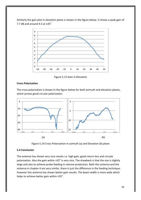
Similarly the gain plot in elevation plane is shown in the figure below. It shows a peak gain of<br />
7.7 dB and around 4.5 at ±35 o .<br />
Cross Polarization<br />
Figure 5.13 Gain in Elevation<br />
The cross polarization is shown in the figure below for both azimuth and elevation planes,<br />
which proves good circular polarization.<br />
0<br />
-‐10<br />
-‐20<br />
-‐30<br />
5.4 Conclusion<br />
9<br />
8<br />
7<br />
6<br />
5<br />
4<br />
3<br />
2<br />
1<br />
0<br />
-‐50 -‐40 -‐30 -‐20 -‐10 0 10 20 30 40 50<br />
-‐40<br />
-‐100 -‐50 0 50 100<br />
-‐10<br />
-‐15<br />
-‐100 -‐50 0 50 100<br />
(a) (b)<br />
Figure 5.14 Cross Polarization in azimuth (a) and Elevation (b) plane<br />
The antenna has shown very nice results i.e. high gain, good return loss and circular<br />
polarization. Also the gain within ±35 o is very nice. The drawback is that the size is slightly<br />
large and also to achieve probe feeding in volume production. Both this antenna and the<br />
antenna in chapter 4 are very similar, there is just the difference in the feeding technique,<br />
however this antenna has shown better gain results. The beam width is more wide which<br />
helps to achieve better gain within ±35 o .<br />
0<br />
-‐5<br />
44