Service Bulletin 031 - Hartzell Engine Technologies
Service Bulletin 031 - Hartzell Engine Technologies
Service Bulletin 031 - Hartzell Engine Technologies

You also want an ePaper? Increase the reach of your titles
YUMPU automatically turns print PDFs into web optimized ePapers that Google loves.
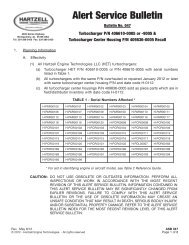
Typical<br />
Turbocharger<br />
Exhaust Tube<br />
Installation<br />
Shown<br />
Figure 1 - “V” band Clamp<br />
Showing Gap<br />
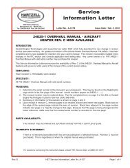
Figure 3 - Turbine Housing<br />
Trouble Area<br />
Figure 2 - Gap Inspection<br />
Area<br />
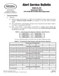
Figure 4 - Spare Part<br />
Code Marking<br />
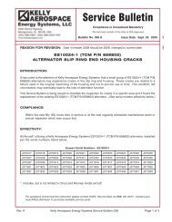
7. Once the turbocharger has been repaired, visually inspect for condition and orientation of the turbine<br />
housing then, using a 1/8” metal stamp of an upper case “I”, stamp the turbine housing in the area shown<br />
in Figure 3. Care must be taken not to extend stamp within 1/8” of the mating edge as it may bulge and<br />
distort the mating surface. When stamped, proceed with the installation.<br />
8. Utilizing the applicable aircraft, STC holder and/or engine manufacturers maintenance manuals or<br />
service instructions, re-install the turbocharger assembly.<br />
Page 4 of 5 Kelly Aerospace Power Systems <strong>Service</strong> <strong>Bulletin</strong> <strong>031</strong> Rev. New