Modeling and Simulation of Press and Sinter ... - ASM International
Modeling and Simulation of Press and Sinter ... - ASM International
Modeling and Simulation of Press and Sinter ... - ASM International

Create successful ePaper yourself
Turn your PDF publications into a flip-book with our unique Google optimized e-Paper software.
326 / <strong>Simulation</strong> <strong>of</strong> Powder Metallurgy Processes<br />
Fig. 3<br />
sm is the flow stress <strong>of</strong> the matrix material,<br />
which is expressed as:<br />
sm ¼ a þ be n m<br />
Z<br />
(Eq 3)<br />
where em is the effective strain <strong>of</strong> the matrix<br />
material.<br />
A series <strong>of</strong> uniaxial compression tests are<br />
performed without wall lubricant, then the<br />
Coulomb frictional coefficient is obtained<br />
by FEM simulation.<br />
Figure 4 is an illustration <strong>of</strong> the compaction<br />
curve for an iron-base powder (Distaloy AE,<br />
Höganäs) in a simple cylindrical geometry.<br />
Uniaxial compression tests are provided for<br />
two samples: the smaller sample <strong>of</strong> 4.5 g in a<br />
12 mm diameter die with die wall lubrication,<br />
<strong>and</strong> the larger sample <strong>of</strong> 9.3 g without wall<br />
lubrication. By curve fitting, the six material<br />
parameters are (Ref 24):<br />
Y<br />
(a)<br />
X<br />
Z<br />
Y<br />
(c)<br />
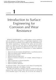
<strong>Modeling</strong> <strong>and</strong> mesh-generation example showing the simulation <strong>of</strong> compaction <strong>and</strong> sintering for an oxygen<br />
sensor housing. (a) Mesh generation for the compact. (b) <strong>Modeling</strong> <strong>of</strong> punches <strong>and</strong> dies during compaction<br />
for the press simulation. (c) <strong>Modeling</strong> <strong>of</strong> compact in contact with the substrate during sintering simulation<br />
X<br />
Z<br />
Y<br />
(b)<br />
a ¼ 6:20; g ¼ 1:03; m¼ 7:40;a¼ 184 MPa;<br />
b ¼ 200 MPa; <strong>and</strong> n ¼ 0:240<br />
By FEM simulation, the Coulomb frictional<br />
coefficient was obtained as 0.1. Table 1 shows<br />
the example <strong>of</strong> a complete set <strong>of</strong> material properties<br />
<strong>of</strong> an iron-base powder as input data for<br />
the compaction simulation.<br />
Verification <strong>of</strong> the predicted density gradients<br />
in the green compact has been approached<br />
by many techniques. The most reliable, direct,<br />
<strong>and</strong> sensitive comes from taking hardness or<br />
microhardness traces on a polished cross section.<br />
Thus, to verify the compaction simulation<br />
results, the relationship between hardness <strong>and</strong><br />
green density is conducted according to the following<br />
procedure:<br />
Use the same samples as used for obtaining<br />
the material parameters.<br />
X<br />
Presinter the compacts at a temperature sufficient<br />
to bond the particles but below the<br />
temperature range where dimensional<br />
change or chemical reactions occur.<br />
Carefully prepare a metallographic cross<br />
section <strong>of</strong> the presintered samples <strong>and</strong> treat<br />
with a vacuum annealing cycle to minimize<br />
any hardness change induced by the cutting<br />
process.<br />
Measure the hardness <strong>of</strong> each sample with a<br />
known green density, <strong>and</strong> from that develop<br />
a correlation between density <strong>and</strong> hardness.<br />
Apply the same procedure <strong>and</strong> hardness traces<br />
to real components, <strong>and</strong> from precise measurements<br />
<strong>of</strong> hardness <strong>and</strong> location develop a contour<br />
plot <strong>of</strong> the green density distribution for<br />
comparison with the computer simulation.<br />
As an example, Fig. 5 is a plot <strong>of</strong> the correlation<br />
between green density <strong>and</strong> hardness for<br />
the WC-Co system. For this plot, the presintering<br />
cycle <strong>of</strong> the WC-Co system was at 790 o C<br />
for 30 min, <strong>and</strong> the annealing cycle was at<br />
520 o C for 60 min; in this case, a Rockwell<br />
15T hardness scale was used. The obtained correlation<br />
is (Ref 35):<br />
D¼0:638 þ 1:67 10 3 H 5:44 10 7 H 2<br />
(Eq 4)<br />
where H is the 15T Rockwell hardness number,<br />
<strong>and</strong> D is the fractional density. Figure 6 compares<br />
the simulation results taken from a commercial<br />
s<strong>of</strong>tware package (PMsolver) with the<br />
experimental results for a cutting tool geometry<br />
formed from a cemented carbide powder, based<br />
on Eq 4.<br />
Material Properties <strong>and</strong> Verification for<br />
<strong>Sinter</strong>ing<br />
In the development <strong>of</strong> a constitutive model<br />
for sintering simulation, a wide variety <strong>of</strong> tests<br />
are required, including data on grain growth,<br />
densification (or swelling), <strong>and</strong> distortion.<br />
These are approached as follows:<br />
Grain growth: Quenching tests are conducted<br />
from various points in the heating<br />
cycle, <strong>and</strong> the mounted cross sections are<br />
analyzed to obtain grain-size data to implement<br />
grain-growth models. A vertical<br />
quench furnace is used to sinter the compacts<br />
to various points in the sintering cycle<br />
<strong>and</strong> then to quench those compacts in water.<br />
This gives density, chemical dissolution (for<br />
example, diffusion <strong>of</strong> one constituent into<br />
another), <strong>and</strong> grain size as instantaneous<br />
functions <strong>of</strong> temperature <strong>and</strong> time. The<br />
quenched samples are sectioned, mounted,<br />
<strong>and</strong> polished prior to optical or scanning<br />
electron microscopy (SEM). Today (2009),<br />
automated quantitative image analysis provides<br />
rapid determination <strong>of</strong> density, grain<br />
size, <strong>and</strong> phase content versus location in<br />
the compact. Usually during sintering, the<br />
mean grain size, G, varies from the starting<br />
mean grain size, G0 (determined on the