Modeling and Simulation of Press and Sinter ... - ASM International
Modeling and Simulation of Press and Sinter ... - ASM International
Modeling and Simulation of Press and Sinter ... - ASM International

You also want an ePaper? Increase the reach of your titles
YUMPU automatically turns print PDFs into web optimized ePapers that Google loves.
<strong>ASM</strong> H<strong>and</strong>book, Volume 22B, Metals Process <strong>Simulation</strong><br />
D.U. Furrer <strong>and</strong> S.L. Semiatin, editors<br />
<strong>Modeling</strong> <strong>and</strong> <strong>Simulation</strong> <strong>of</strong> <strong>Press</strong> <strong>and</strong><br />
<strong>Sinter</strong> Powder Metallurgy<br />
Suk Hwan Chung, Hyundai Steel Company<br />
Young-Sam Kwon, CetaTech, Inc.<br />
Seong Jin Park, Pohang University <strong>of</strong> Science <strong>and</strong> Technology<br />
R<strong>and</strong>all M. German, San Diego State University<br />
EFFECTIVE COMPUTER SIMULATIONS<br />
<strong>of</strong> metal powder compaction <strong>and</strong> sintering are<br />
at the top <strong>of</strong> the powder metallurgy industry’s<br />
wish list. There is much anticipated advantage<br />
to such efforts, yet there are problems that will<br />
inhibit widespread implementation. <strong>Press</strong>-sinter<br />
powder metallurgy computer simulations currently<br />
focus on the use <strong>of</strong> minimal input data<br />
to help with process setup. Although the simulations<br />
are reasonably accurate, a large data array<br />
is required to hone in on current industrial practice.<br />
For example, final dimensions for automotive<br />
transmission gears are required to be held<br />
within 10 mm, but the simulations are not capable<br />
<strong>of</strong> such accuracy. Simple factors such as<br />
frictional tool heating are missing from the<br />
simulations. Additionally, powders vary in particle<br />
size distribution between production lots,<br />
but the simulations assume a nominally uniform<br />
powder. Because it is expensive to test each<br />
powder lot, the logic is to assume a nominal<br />
set <strong>of</strong> characteristics. In production, such process<br />
<strong>and</strong> powder variations are h<strong>and</strong>led by constant<br />
adaptive control techniques. As an<br />
example, when an outside door is opened on<br />
the press room, it is common that press adjustments<br />
will be required to hold sintered dimensions.<br />
The press-sinter powder metallurgy<br />
simulations have not advanced to such levels<br />
<strong>of</strong> sophistication. Instead, the press-sinter powder<br />
metallurgy simulations are used to help set<br />
up production operations, with heavy reliance<br />
on experienced operators to make final trial<strong>and</strong>-error<br />
adjustments.<br />
In practice, the variations in powder, press,<br />
tooling, <strong>and</strong> other process variables are h<strong>and</strong>led<br />
through skilled technicians, quality charts, <strong>and</strong><br />
adaptive process control that relies on frequent<br />
sampling <strong>and</strong> periodic equipment adjustments.<br />
The gap between press-sinter practice <strong>and</strong> modeling<br />
may close if more rapid data-generation<br />
routes were developed. For example, a study<br />
on modeling the press-sinter production <strong>of</strong> a<br />
main bearing cap required 10,000 measures to<br />
isolate the behavior. It is not economically<br />
feasible to repeat this testing for each 20 ton<br />
lot <strong>of</strong> powder. Even so, a great benefit comes<br />
from the fact that the computer simulations<br />
have forced the technical community to organize<br />
our knowledge <strong>and</strong> determine where there<br />
are problems.<br />
Computer simulations <strong>of</strong> press-sinter operations<br />
trace to the 1960s (Ref 1 to 20). The<br />
early simulations were generally unstable <strong>and</strong><br />
two-dimensional (for example, the sintering<br />
<strong>of</strong> aligned wires). By 1975, a variety <strong>of</strong> twodimensional<br />
sintering approaches existed.<br />
With the expansion in computer power, the<br />
implementation <strong>of</strong> three-dimensional simulations<br />
arose to provide realistic outputs. In<br />
more recent times, the simulations have<br />
provided valuable three-dimensional treatments<br />
to predict the final component size <strong>and</strong><br />
shape after sintering. Because the pressed<br />
green body is not homogeneous, backward<br />
solutions are desired to select the powder,<br />
compaction, <strong>and</strong> sintering attributes required<br />
to deliver the target properties with different<br />
tool designs, compaction presses, <strong>and</strong> sintering<br />
furnaces.Inbuildingtowardthisgoal,various<br />
simulation types have been evaluated: Monte<br />
Carlo, finite difference, discrete element, finite<br />
element, fluid mechanics, continuum mechanics,<br />
neural network, <strong>and</strong> adaptive learning.<br />
Unfortunately, the input data <strong>and</strong> some <strong>of</strong> the<br />
basic relations are not well developed; accurate<br />
data are missing for most materials under<br />
the relevant conditions. For example, rarely is<br />
the strength measured for a steel alloy at the<br />
typical 1120 C sintering temperature. Further,<br />
constitutive models do not exist for the conditions<br />
relevant to sintering; for example, friction<br />
in die compaction changes during the<br />
split-second pressure stroke, because lubricant<br />
(polymer) particles deform <strong>and</strong> undergo viscous<br />
flow to the die wall, effectively changing<br />
friction constantly during compaction. Thus,<br />
the simulations are approximations using<br />
extrapolated data <strong>and</strong> simplified relations. For<br />
this reason, computer simulations <strong>of</strong> press-<br />
sinter routes work best in the setup mode.<br />
The simulations help define the processing<br />
window <strong>and</strong> set initial operating parameters.<br />
Presented here is information relevant to computer<br />
simulation <strong>of</strong> first-article production,<br />
what is best termed setup calculations, realizing<br />
that practice relies heavily on adaptive<br />
process control to keep the product in specification<br />
after the initial setup is accomplished.<br />
Brief History<br />
Copyright # 2010, <strong>ASM</strong> <strong>International</strong> ®<br />
All rights reserved.<br />
www.asminternational.org<br />
The first major publication on computer simulation<br />
<strong>of</strong> sintering came out in 1965 (Ref 1).<br />
Early simulations were two-dimensional (sintering<br />
two wires) with a single diffusion mechanism.<br />
These simulations were slow, requiring<br />
ten times more computer time than the actual<br />
physical sintering time. Most damaging, these<br />
early models were unstable, because they lost<br />
volume <strong>and</strong> increased energy. However, within<br />
20 years the concept was extended to include<br />
multiple transport mechanisms, multiple sintering<br />
stages, <strong>and</strong> even pressure-assisted sintering<br />
(Ref 6, 9 to 11). These simulations predicted<br />
density versus compaction pressure, sintering<br />
time, peak temperature, heating rate, green density,<br />
<strong>and</strong> particle size.<br />
One <strong>of</strong> the first realizations was the limitations<br />
arising from the assumed isothermal<br />
conditions <strong>and</strong> simplistic microstructure coarsening.<br />
Dilatometry experiments show that most<br />
sintering occurs on the way to the peak temperature,<br />
so isothermal models poorly reflect actual<br />
behavior (Ref 20). Indeed, production powder<br />
metallurgy <strong>of</strong>ten simply “kisses” the peak temperature,<br />
a situation far from what is assumed<br />
in the simulations. Also, the assumed homogeneous<br />
<strong>and</strong> ideal microstructure unrealistically<br />
limits the models. Today (2009), the sintering<br />
body first treated with a compaction or shaping<br />
simulation to predict the green microstructure<br />
gradients, <strong>and</strong> subsequent sintering simulations,<br />
use those density gradients, via finite-element
324 / <strong>Simulation</strong> <strong>of</strong> Powder Metallurgy Processes<br />
analysis, to predict the final size, shape, <strong>and</strong><br />
properties (Ref 16 to 19).<br />
Theoretical Background <strong>and</strong><br />
Governing Equations<br />
The methodologies used to model the press<br />
<strong>and</strong> sinter powder metallurgy include continuum,<br />
micromechanical, multiparticle, <strong>and</strong><br />
molecular dynamics approaches. These differ<br />
in length scales. Among the methodologies,<br />
continuum models have the benefit <strong>of</strong> shortest<br />
computing time, with an ability to predict relevant<br />
attributes such as the component density,<br />
grain size, <strong>and</strong> shape.<br />
Mass, volume, <strong>and</strong> momentum conservation<br />
are evoked in the continuum approach.<br />
Although such assumptions may seem obvious,<br />
powder metallurgy processes are ill-behaved<br />
<strong>and</strong> difficult to properly simulate. For example,<br />
polymers are added to the powder for tool<br />
lubrication, but the polymers are pyrolyzed<br />
during sintering, resulting in 0.5 to 1.5 wt%<br />
mass loss. Likewise, pore space is not conserved<br />
during compaction <strong>and</strong> sintering, so<br />
bulk volume is not conserved. Even so, mass<br />
conservation equations are invoked to track<br />
densification, while momentum conservation<br />
is used to follow force equilibrium, including<br />
the distortion effect from gravity. Energy conservation<br />
is also essential in the continuum<br />
approach. However, it is typical to assume temperature<br />
is uniform in the compact—set to<br />
room temperature during compaction <strong>and</strong> following<br />
an idealized thermal cycle (<strong>of</strong>ten isothermal)<br />
during sintering. Both are incorrect,<br />
because tool heating occurs with repeated compaction<br />
strokes, <strong>and</strong> compact position in the<br />
sintering furnace gives a lagging thermal history<br />
that depends on location. Indeed, because<br />
dimensional precision is the key to powder<br />
metallurgy, statistical audits have repeatedly<br />
found that subtle factors such as position in<br />
the furnace are root causes <strong>of</strong> dimensional scatter.<br />
For example, fluid flow <strong>and</strong> heat-transport<br />
calculations show considerable temperature differences<br />
associated with atmosphere flow <strong>and</strong><br />
component shadowing within a furnace.<br />
Because such details are not embraced by the<br />
models, the typical assumption is to ignore<br />
temperature distribution within the component,<br />
yet such factors are known to cause part distortion<br />
during production.<br />
Additionally, constitutive relations are<br />
required to describe the response <strong>of</strong> the compact<br />
to mechanical force during compaction<br />
<strong>and</strong> sintering. Many powder metallurgy materials<br />
are formed by mixing powders that melt,<br />
react, diffuse, <strong>and</strong> alloy during sintering. This<br />
requires sophistication in the models to add<br />
phase transformations, alloying, <strong>and</strong> other factors,<br />
many <strong>of</strong> which depend on particle size<br />
<strong>and</strong> other variations (Ref 15). From conservation<br />
laws <strong>and</strong> constitutive relations, a system<br />
<strong>of</strong> partial differential equations is created that<br />
includes the initial <strong>and</strong> boundary conditions.<br />
These must be integrated with microstructure<br />
<strong>and</strong> property models so that final compact properties<br />
can be predicted. Because the constitutive<br />
relations for compaction <strong>and</strong> sintering are<br />
completely different, they are described here<br />
in two separate sections.<br />
Constitutive Relation during<br />
Compaction<br />
Continuum plasticity models are frequently<br />
used to describe the mechanical response <strong>of</strong><br />
metal powders during compaction. These phenomenological<br />
models, originally developed in<br />
soil mechanics, are characterized by a yield criterion,<br />
a hardening function, <strong>and</strong> a flow rule.<br />
Representative models include those known as<br />
the Cam-Clay (Ref 21), Drucker-Prager-Cap<br />
(Ref 22), <strong>and</strong> Shima-Oyane (Ref 23) models.<br />
Of these, the most successful for metal powders<br />
has been the Shima-Oyane model, although for<br />
ceramics, soils, <strong>and</strong> minerals, other relations are<br />
generally more successful.<br />
The typical initial <strong>and</strong> boundary conditions<br />
during compaction are as follows:<br />
Initial condition for the powder: Tap density<br />
Boundary conditions: Velocity prescribed in<br />
upper <strong>and</strong> bottom punches <strong>and</strong> friction condition<br />
in the tooling side wall; usually<br />
assumed the same for all tool surfaces independent<br />
<strong>of</strong> wear <strong>and</strong> independent <strong>of</strong> lubricant<br />
flow during the compaction stroke<br />
During compaction <strong>and</strong> ejection, a damage<br />
model, such as the Drucker-Prager failure surface<br />
(Ref 22) <strong>and</strong> failure separation length<br />
(FSL) idea (Ref 24), is required. To predict crack<br />
formation, the FSL assumes there is an accumulated<br />
separation length from the Drucker-Prager<br />
failure surface, which provides the possibility<br />
Fig. 1<br />
<strong>of</strong> crack formation, as shown in Fig. 1. The equation<br />
for the FSL is expressed as:<br />
FS ¼ q þ p tan b d (Eq 1)<br />
where q <strong>and</strong> p are the effective stress <strong>and</strong> hydrostatic<br />
pressure, respectively. Note that d <strong>and</strong> b<br />
are the <strong>of</strong>fset stress <strong>and</strong> slope, respectively, for<br />
the Drucker-Prager failure surface shown in<br />
Fig. 1. Because the models predict green density<br />
versus location, defect sensitivity is possible.<br />
For example, elastic relaxation occurs on<br />
ejection, <strong>and</strong> if the stress exceeds the green<br />
strength, then green cracking occurs. It is in this<br />
area that the compaction models are most<br />
effective.<br />
Constitutive Relation during <strong>Sinter</strong>ing<br />
Continuum modeling is the most relevant<br />
approach to modeling grain growth, densification,<br />
<strong>and</strong> deformation during sintering. Key contributions<br />
were by Ashby (Ref 6, 9), McMeeking<br />
<strong>and</strong> Kuhn (Ref 25), Olevsky et al. (Ref 17, 19),<br />
Riedel et al. (Ref 13, 26, 27), Bouvard <strong>and</strong> Meister<br />
(28), Cocks (29), Kwon et al. (Ref 30, 31), <strong>and</strong><br />
Bordia <strong>and</strong> Scherer (Ref 32 to 34) based on a sintering<br />
mechanism such as surface diffusion,<br />
grain-boundary diffusion, volume diffusion, viscous<br />
flow (for amorphous materials), plastic flow<br />
(for crystalline materials), evaporation condensation,<br />
<strong>and</strong> rearrangement. For industrial application,<br />
the phenomenological models are used<br />
for sintering simulations with the following key<br />
physical parameters:<br />
<strong>Sinter</strong>ing stress (Ref 20) is a driving force <strong>of</strong><br />
sintering due to interfacial energy <strong>of</strong> pores<br />
<strong>and</strong> grain boundaries. <strong>Sinter</strong>ing stress depends<br />
on the material surface energy, density, <strong>and</strong><br />
geometric parameters such as grain size when<br />
all pores are closed in the final stage.<br />
Definition <strong>of</strong> failure separation length (FSL) based on Shima-Oyane yield model <strong>and</strong> Drucker-Prager failure<br />
surface. d, <strong>of</strong>fset stress; b, slope
Effective bulk viscosity is a resistance to<br />
densification during sintering <strong>and</strong> is a function<br />
<strong>of</strong> the material, porosity, grain size,<br />
<strong>and</strong> temperature. The model <strong>of</strong> the effective<br />
bulk viscosity has various forms according<br />
to the assumed dominant sintering<br />
mechanism.<br />
Effective shear viscosity is a resistance to<br />
deformation during sintering <strong>and</strong> is also a<br />
function <strong>of</strong> the material, porosity, grain size,<br />
<strong>and</strong> temperature. Several rheological models<br />
for the effective bulk viscosity are available.<br />
The preceding parameters are a function <strong>of</strong><br />
grain size. Therefore, a grain-growth model is<br />
needed for accurate prediction <strong>of</strong> densification<br />
<strong>and</strong> deformation during sintering.<br />
Typical initial <strong>and</strong> boundary conditions for<br />
the sintering simulations include:<br />
Initial condition: Mean particle size <strong>and</strong><br />
grain size <strong>of</strong> the green compact for grain<br />
growth <strong>and</strong> initial green density distribution<br />
for densification obtained from compaction<br />
simulations<br />
Boundary conditions: Surface energy condition<br />
imposed on the free surface <strong>and</strong> friction<br />
condition <strong>of</strong> the component depending on its<br />
size, shape, <strong>and</strong> contact with the support<br />
substrate<br />
The initial green density distribution within the<br />
pressed body raises the necessity <strong>of</strong> starting the<br />
sintering simulation with the output from an<br />
accurate compaction simulation, because die<br />
compaction induces green density gradients that<br />
depend on the material, pressure, rate <strong>of</strong> pressurization,<br />
tool motions, <strong>and</strong> lubrication. The<br />
initial <strong>and</strong> boundary conditions help determine<br />
the shape distortion during sintering from gravity,<br />
nonuniform heating, <strong>and</strong> the green body<br />
density gradients.<br />
Numerical <strong>Simulation</strong>. Even though many<br />
numerical methods have been developed, the<br />
finite-element method (FEM) is most popular<br />
for continuum models <strong>of</strong> the press <strong>and</strong> sinter<br />
process. The FEM approach is a numerical<br />
computational method for solving a system <strong>of</strong><br />
differential equations through approximation<br />
functions applied to each element, called<br />
domain-wise approximation. This method is<br />
very powerful for the typical complex geometries<br />
encountered in powder metallurgy. This is<br />
one <strong>of</strong> the earliest techniques applied to materials<br />
modeling <strong>and</strong> is used throughout industry<br />
today (2009). Many powerful commercial s<strong>of</strong>tware<br />
packages are available for calculating<br />
two- <strong>and</strong> three-dimensional thermomechanical<br />
processes such as found in press <strong>and</strong> sinter powder<br />
metallurgy.<br />
To increase the accuracy <strong>and</strong> convergence<br />
speed for the press <strong>and</strong> sinter simulations,<br />
developers <strong>of</strong> the simulation tools have selected<br />
explicit <strong>and</strong> implicit algorithms for time<br />
advancement, numerical contact algorithms for<br />
problems such as surface separation, <strong>and</strong><br />
remeshing algorithms as required for large<br />
<strong>Modeling</strong> <strong>and</strong> <strong>Simulation</strong> <strong>of</strong> <strong>Press</strong> <strong>and</strong> <strong>Sinter</strong> Powder Metallurgy / 325<br />
deformations such as seen in some sintered<br />
materials, where up to 25% dimensional contraction<br />
is possible.<br />
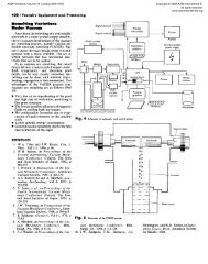
Figure 2 shows the typical procedure for<br />
computer simulation for the press-sinter<br />
process, which consists <strong>of</strong> five components:<br />
simulation tool, pre- <strong>and</strong> postprocessors, optimization<br />
algorithm, <strong>and</strong> experimental capability.<br />
Pre- <strong>and</strong> postprocessors are important for<br />
using the simulation tools efficiently. The preprocessor<br />
is a s<strong>of</strong>tware tool to prepare input<br />
data for the simulation tool, including computational<br />
domain preparation such as geometry<br />
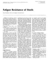
modeling <strong>and</strong> mesh generator. Figure 3 is an<br />
example <strong>of</strong> the component, compaction, <strong>and</strong><br />
sintering models, in this case for an oxygen<br />
sensor housing. Executing this model requires<br />
considerable input, including a material property<br />
database (including strain effects during<br />
compaction <strong>and</strong> temperature effects during sintering)<br />
<strong>and</strong> a processing condition database<br />
(loading schedule <strong>of</strong> punches <strong>and</strong> dies for compaction<br />
simulation <strong>and</strong> heating cycle for sintering<br />
simulation). A postprocessor is a s<strong>of</strong>tware<br />
tool to visualize <strong>and</strong> analyze the simulation<br />
results, which enhances the usefulness <strong>of</strong> the<br />
simulations. From the st<strong>and</strong>point <strong>of</strong> process<br />
setup calculations, the optimization algorithm<br />
is essential to maximize computer simulation<br />
capability providing the optimum part, die,<br />
<strong>and</strong> process condition design. Experimental<br />
capability is very important in computer simulation,<br />
providing a means to evaluate changes<br />
in materials, powders, compaction schedules,<br />
heating cycles, <strong>and</strong> generally to provide verification<br />
<strong>of</strong> the simulation results.<br />
Experimental Determination <strong>of</strong><br />
Material Properties <strong>and</strong> <strong>Simulation</strong><br />
Verification<br />
Material Properties <strong>and</strong> Verification for<br />
Compaction<br />
One <strong>of</strong> the first needs is to measure the powder<br />
density as a function <strong>of</strong> applied pressure to<br />
generate the material parameters in the constitutive<br />
model for compaction, including the<br />
Coulomb friction coefficient between the powder<br />
<strong>and</strong> die. Note that these factors vary with<br />
the powder lot, lubricant, tool material, <strong>and</strong><br />
even tool temperature. The procedure to obtain<br />
the material properties based on the generalized<br />
Shima-Oyane model is as follows (Ref 24):<br />
Measure the pycnometer <strong>and</strong> tap densities <strong>of</strong><br />
the powder.<br />
Conduct a series <strong>of</strong> uniaxial compression<br />
tests with die wall lubrication to minimize<br />
the die wall friction effect. The tap density<br />
is considered the starting point (after particle<br />
rearrangement) corresponding to zero compaction<br />
pressure. By curve fitting, six material<br />
parameters (a, g, m, a, b, <strong>and</strong> n) are<br />
determined for the yield surface, F:<br />
F ¼ q<br />
Fig. 2 Typical procedure for computer simulation for press <strong>and</strong> sinter process<br />
sm<br />
2<br />
það1DÞ g p<br />
sm<br />
D m<br />
(Eq 2)<br />
where q <strong>and</strong> p are the effective stress <strong>and</strong><br />
hydrostatic stress or pressure, respectively;<br />
D is the relative or fractional density; <strong>and</strong>
326 / <strong>Simulation</strong> <strong>of</strong> Powder Metallurgy Processes<br />
Fig. 3<br />
sm is the flow stress <strong>of</strong> the matrix material,<br />
which is expressed as:<br />
sm ¼ a þ be n m<br />
Z<br />
(Eq 3)<br />
where em is the effective strain <strong>of</strong> the matrix<br />
material.<br />
A series <strong>of</strong> uniaxial compression tests are<br />
performed without wall lubricant, then the<br />
Coulomb frictional coefficient is obtained<br />
by FEM simulation.<br />
Figure 4 is an illustration <strong>of</strong> the compaction<br />
curve for an iron-base powder (Distaloy AE,<br />
Höganäs) in a simple cylindrical geometry.<br />
Uniaxial compression tests are provided for<br />
two samples: the smaller sample <strong>of</strong> 4.5 g in a<br />
12 mm diameter die with die wall lubrication,<br />
<strong>and</strong> the larger sample <strong>of</strong> 9.3 g without wall<br />
lubrication. By curve fitting, the six material<br />
parameters are (Ref 24):<br />
Y<br />
(a)<br />
X<br />
Z<br />
Y<br />
(c)<br />
<strong>Modeling</strong> <strong>and</strong> mesh-generation example showing the simulation <strong>of</strong> compaction <strong>and</strong> sintering for an oxygen<br />
sensor housing. (a) Mesh generation for the compact. (b) <strong>Modeling</strong> <strong>of</strong> punches <strong>and</strong> dies during compaction<br />
for the press simulation. (c) <strong>Modeling</strong> <strong>of</strong> compact in contact with the substrate during sintering simulation<br />
X<br />
Z<br />
Y<br />
(b)<br />
a ¼ 6:20; g ¼ 1:03; m¼ 7:40;a¼ 184 MPa;<br />
b ¼ 200 MPa; <strong>and</strong> n ¼ 0:240<br />
By FEM simulation, the Coulomb frictional<br />
coefficient was obtained as 0.1. Table 1 shows<br />
the example <strong>of</strong> a complete set <strong>of</strong> material properties<br />
<strong>of</strong> an iron-base powder as input data for<br />
the compaction simulation.<br />
Verification <strong>of</strong> the predicted density gradients<br />
in the green compact has been approached<br />
by many techniques. The most reliable, direct,<br />
<strong>and</strong> sensitive comes from taking hardness or<br />
microhardness traces on a polished cross section.<br />
Thus, to verify the compaction simulation<br />
results, the relationship between hardness <strong>and</strong><br />
green density is conducted according to the following<br />
procedure:<br />
Use the same samples as used for obtaining<br />
the material parameters.<br />
X<br />
Presinter the compacts at a temperature sufficient<br />
to bond the particles but below the<br />
temperature range where dimensional<br />
change or chemical reactions occur.<br />
Carefully prepare a metallographic cross<br />
section <strong>of</strong> the presintered samples <strong>and</strong> treat<br />
with a vacuum annealing cycle to minimize<br />
any hardness change induced by the cutting<br />
process.<br />
Measure the hardness <strong>of</strong> each sample with a<br />
known green density, <strong>and</strong> from that develop<br />
a correlation between density <strong>and</strong> hardness.<br />
Apply the same procedure <strong>and</strong> hardness traces<br />
to real components, <strong>and</strong> from precise measurements<br />
<strong>of</strong> hardness <strong>and</strong> location develop a contour<br />
plot <strong>of</strong> the green density distribution for<br />
comparison with the computer simulation.<br />
As an example, Fig. 5 is a plot <strong>of</strong> the correlation<br />
between green density <strong>and</strong> hardness for<br />
the WC-Co system. For this plot, the presintering<br />
cycle <strong>of</strong> the WC-Co system was at 790 o C<br />
for 30 min, <strong>and</strong> the annealing cycle was at<br />
520 o C for 60 min; in this case, a Rockwell<br />
15T hardness scale was used. The obtained correlation<br />
is (Ref 35):<br />
D¼0:638 þ 1:67 10 3 H 5:44 10 7 H 2<br />
(Eq 4)<br />
where H is the 15T Rockwell hardness number,<br />
<strong>and</strong> D is the fractional density. Figure 6 compares<br />
the simulation results taken from a commercial<br />
s<strong>of</strong>tware package (PMsolver) with the<br />
experimental results for a cutting tool geometry<br />
formed from a cemented carbide powder, based<br />
on Eq 4.<br />
Material Properties <strong>and</strong> Verification for<br />
<strong>Sinter</strong>ing<br />
In the development <strong>of</strong> a constitutive model<br />
for sintering simulation, a wide variety <strong>of</strong> tests<br />
are required, including data on grain growth,<br />
densification (or swelling), <strong>and</strong> distortion.<br />
These are approached as follows:<br />
Grain growth: Quenching tests are conducted<br />
from various points in the heating<br />
cycle, <strong>and</strong> the mounted cross sections are<br />
analyzed to obtain grain-size data to implement<br />
grain-growth models. A vertical<br />
quench furnace is used to sinter the compacts<br />
to various points in the sintering cycle<br />
<strong>and</strong> then to quench those compacts in water.<br />
This gives density, chemical dissolution (for<br />
example, diffusion <strong>of</strong> one constituent into<br />
another), <strong>and</strong> grain size as instantaneous<br />
functions <strong>of</strong> temperature <strong>and</strong> time. The<br />
quenched samples are sectioned, mounted,<br />
<strong>and</strong> polished prior to optical or scanning<br />
electron microscopy (SEM). Today (2009),<br />
automated quantitative image analysis provides<br />
rapid determination <strong>of</strong> density, grain<br />
size, <strong>and</strong> phase content versus location in<br />
the compact. Usually during sintering, the<br />
mean grain size, G, varies from the starting<br />
mean grain size, G0 (determined on the
Fig. 4<br />
Example compaction curve for an iron-base powder showing the relative density model results versus<br />
compaction pressure with no friction <strong>and</strong> with a friction coefficient <strong>of</strong> 0.1 for two compact samples.<br />
Source: Ref 24<br />
Fig. 6<br />
Comparison between the computer-simulated green density gradients (PMsolver) <strong>and</strong> the experimental results<br />
taken from hardness tests on a cross-sectioned green compact <strong>of</strong> a cutting tool formed from WC-Co powder.<br />
Source: Ref 35<br />
green compact). A new master sintering<br />
curve concept is applied to fit the experimental<br />
grain-size data to an integral work<br />
<strong>of</strong> sintering (Ref 36), because actual cycles<br />
are a complex combination <strong>of</strong> heats <strong>and</strong><br />
holds. The resulting material parameters<br />
<strong>Modeling</strong> <strong>and</strong> <strong>Simulation</strong> <strong>of</strong> <strong>Press</strong> <strong>and</strong> <strong>Sinter</strong> Powder Metallurgy / 327<br />
trace to an apparent activation energy as<br />
the only adjustable parameter. Figure 7<br />
shows SEM micrographs after a quenching<br />
test <strong>and</strong> grain-growth modeling for a<br />
W-8.4wt%Ni-3.6wt%Fe mixed powder compact<br />
during liquid-phase sintering.<br />
Table 1 Complete set <strong>of</strong> material<br />
properties for die compaction <strong>of</strong> an ironbase<br />
powder<br />
Densities Pycnometer density 7.8 g/cm 3<br />
Fractional tap density 0.45<br />
Yield function a 6.2<br />
(Shima-Oyane) g 1.03<br />
m 7.4<br />
Flow stress <strong>of</strong> matrix a 184 MPa<br />
materials (work b 200 MPa<br />
hardening) n 0.24<br />
Friction coefficient 0.1<br />
Failure surface d 0.01<br />
tan b 3.41<br />
Source: Ref 24<br />
Fig. 5<br />
Plot <strong>of</strong> relative density <strong>and</strong> Rockwell 15T<br />
hardness scale for the die compaction <strong>of</strong> a<br />
WC-Co powder. Source: Ref 35<br />
Densification: To obtain material parameters<br />
for densification, constant heating rate dilatometry<br />
is used for in situ measurement <strong>of</strong><br />
shrinkage, shrinkage rate, <strong>and</strong> temperature.<br />
By fitting the experimental data to models<br />
that include the sintering stress, ss, <strong>and</strong> bulk<br />
viscosity, K, as functions <strong>of</strong> density <strong>and</strong><br />
grain size, again relying on the master sintering<br />
curve concept (Ref 37), the few<br />
unknown material parameters are extracted.<br />
Figure 8 shows the dilatometry data <strong>and</strong><br />
model curve-fitting results used to obtain<br />
the missing material parameters during sintering<br />
<strong>of</strong> a 316L stainless steel (Ref 38).<br />
Distortion: Powder metallurgy compacts<br />
reach very low strength levels during sintering.<br />
Accordingly, weak forces such as gravity,<br />
substrate friction, <strong>and</strong> nonuniform<br />
heating will induce distortion <strong>and</strong> even<br />
cracking. To obtain the material parameters<br />
related to distortion, three-point bending or<br />
sinter forging experiments are used for in<br />
situ measurement <strong>of</strong> distortion (Ref 39). By<br />
fitting the experimental data with FEM<br />
simulations for shear viscosity, m, with grain<br />
growth, the parameters such as apparent<br />
activation energy <strong>and</strong> reference shear viscosity<br />
are extracted. Figure 9 shows an in situ<br />
bending test <strong>and</strong> FEM results for obtaining<br />
material parameters in shear viscosity for a
328 / <strong>Simulation</strong> <strong>of</strong> Powder Metallurgy Processes<br />
316L stainless steel powder doped with<br />
0.2% B to induce improved sintering.<br />
Such data-extraction techniques have been allied<br />
to several materials, including tungsten alloys,<br />
molybdenum, zirconia, cemented carbides, niobium,<br />
steel, stainless steel, <strong>and</strong> alumina. Table<br />
2 is an example set <strong>of</strong> material properties for W-<br />
8.4 wt%Ni-3.6wt%Fe as used as input data for<br />
the sintering simulation (Ref 40). The preceding<br />
experiment techniques can be used for verification<br />
<strong>of</strong> sintering simulation results.<br />
Demonstration <strong>of</strong> System Use<br />
Time Advance Algorithm <strong>and</strong><br />
Compaction <strong>Simulation</strong> Accuracy<br />
Time advance in the simulation models is a<br />
concern with respect to the balance between<br />
Fig. 7<br />
accuracy <strong>and</strong> computational speed. The explicit<br />
method is fast but sometimes exhibits convergence<br />
<strong>and</strong> accuracy problems, while the implicit<br />
method is accurate but slow. Figure 10 illustrates<br />
this case for a simple cylindrical geometry in the<br />
WC-Co system (Ref 35). As shown in Fig. 10<br />
(b), the implicit method is more accurate for<br />
this case.<br />
Gravitational Distorting in <strong>Sinter</strong>ing<br />
The rheological data for the sintering system<br />
allow the system to respond to the internal sintering<br />
stress that drives densification <strong>and</strong> any<br />
external stress, such as gravity, that drives distortion.<br />
When a compact is sintered to high<br />
density, it is also necessary to induce a low<br />
strength. (The material is thermally s<strong>of</strong>tened<br />
to a point where the internal sintering stress<br />
can induce densification.) Figure 11 shows<br />
sintering simulation results for a tungsten heavy<br />
alloy, relying on test data taken on Earth <strong>and</strong><br />
under microgravity conditions, to then predict<br />
the expected shapes for various gravitational<br />
conditions: Earth, Moon, Mars, <strong>and</strong> in space.<br />
The results show that gravity affects shape distortion<br />
during sintering (Ref 40). Accordingly,<br />
the computer simulations can be used to reverse<br />
engineer the green component geometry to<br />
anticipate the distortion to achieve the desired<br />
sintered part design.<br />
Compaction Optimization<br />
There are two different simulation<br />
approaches used to optimize die compaction.<br />
One is based on the concept <strong>of</strong> design <strong>of</strong><br />
experiment, <strong>and</strong> the other is a derivative-based<br />
optimization scheme. The process designer<br />
must first select a reasonable initial guess, an<br />
(a) Scanning electron micrograph <strong>of</strong> a liquid-phase sintered tungsten heavy alloy (W-8.4wt%Ni-3.6wt%Fe) after quenching. (b) Grain-size model results taken from an<br />
integral work <strong>of</strong> sintering concept that includes only the thermal cycle (time-temperature path) to predict grain size for any point in a heating path for three different<br />
tungsten contents. Source: Ref 36<br />
Fig. 8<br />
Dilatometry data showing in situ shrinkage data during constant heating rate experiments <strong>and</strong> the curve-fitting results used to obtain the material parameters to predict<br />
densification <strong>of</strong> a 316L stainless steel powder. (a) Shrinkage with time. (b) Shrinkage with temperature. Source: Ref 38
Fig. 9<br />
(a) Video image taken during in situ bending test for a 316L stainless steel sample doped with 0.2 wt% B. (b) Finite-element modeling results used to verify the shear viscosity<br />
property as a function <strong>of</strong> time, temperature, grain size, <strong>and</strong> density during heating. Source: Ref 39<br />
Table 2 Complete set <strong>of</strong> material properties for simulating the sintering <strong>of</strong> W-8.4wt%Ni-3.6wt%Fe<br />
Pycnometer density 16.75 g/cm 3<br />
Initial density distribution, r0<br />
Results from press simulation<br />
Initial mean grain size 0.30 mm<br />
Surface energy, g 2.5 J/m 2<br />
Transition temperature from solid state to liquid phase 1460 C<br />
Friction coefficient 0.3<br />
<strong>Sinter</strong>ing stress<br />
ss ¼ 6g r<br />
G<br />
2ð2rr0Þ for r < 0:85<br />
ss ¼ 2g<br />
G<br />
ss ¼ ðr 2<br />
y0<br />
1=3<br />
6r<br />
y<br />
rÞ<br />
objective function that needs to be minimized,<br />
<strong>and</strong> design variables for both approaches.<br />
Figure 12 shows the first approach used to<br />
optimize the loading schedule to generate a<br />
uniform green density during die compaction<br />
(Ref 35). In this case, the target is a cutting<br />
tool formed from WC-Co. The displacement<br />
<strong>of</strong> the upper punch was set as the design variable,<br />
<strong>and</strong> the lower punch displacement was<br />
for r W > 0:95<br />
ðr2 r1Þ ssi þ ðr r1Þ ðr2 r1Þ ssf for 0:85 rW 0:95<br />
State Solid Liquid<br />
Grain growth<br />
dG<br />
dt ¼ k0 expð QG=RT Þ<br />
Gl k0 (m n+1 /s) 2.8 10 13<br />
1.1 10 15<br />
QG (kJ/mol)<br />
l<br />
241<br />
2.0<br />
105<br />
2.0<br />
Bulk viscosity<br />
Shear viscosity<br />
Ki ¼ rðr r0Þ 2<br />
8y 2<br />
TG<br />
0<br />
3<br />
for r<br />
ai expð QD=RT Þ<br />
0:92<br />
Kf ¼ r TG3 for r > 0:92<br />
af expð QD=RT Þ<br />
8y 1=2<br />
0<br />
y 2<br />
0<br />
with af ¼ pffiffiffiffiffiffiffiffiffi<br />
0:08ð0:92<br />
r0Þ 2 ai<br />
TG 3<br />
mi ¼ r2ðr r0Þ 8y0 bi expð<br />
for r<br />
QD=RT Þ<br />
0:92<br />
Kf ¼ r TG<br />
8<br />
3<br />
for r > 0:92<br />
bf expð QD=RT Þ<br />
y0<br />
with bf ¼<br />
0:92ð0:92 r0Þ bi <strong>Modeling</strong> <strong>and</strong> <strong>Simulation</strong> <strong>of</strong> <strong>Press</strong> <strong>and</strong> <strong>Sinter</strong> Powder Metallurgy / 329<br />
automatically calculated because the final<br />
dimension was fixed. The objective function<br />
was set to the st<strong>and</strong>ard deviation in green density,<br />
which is called the nonuniformity, <strong>and</strong> this<br />
was to be minimized. Figure 12(a) plots the<br />
density histograms for five different processing<br />
conditions. The first one (black) is the initial<br />
compaction process design, <strong>and</strong> the fourth one<br />
(yellow) shows the optimum design for<br />
QD (kJ/mol) 250 250<br />
a i (m 6 K/s) 1.3 10 17<br />
5.0 10 17<br />
bi (m 6 K/s) 1.3 10 17<br />
Note that R is the universal gas constant, r is the density, y (= 1 r) is the porosity, y 0 (= 1 r 0) is the initial porosity, <strong>and</strong> r W is the density <strong>of</strong> the tungsten skeleton. Source: Ref 40<br />
1.3 10 12<br />
maximum uniformity with only a change in<br />
the upper punch motion. The density distributions<br />
<strong>of</strong> those two cases are shown in Fig. 12<br />
(b). For optimization in more complicated systems,<br />
the Taguchi method with an orthogonal<br />
array can be used to create simulation experiments<br />
to efficiently isolate solutions.<br />
In using a derivative-based optimization<br />
scheme, it is important to define the searching
330 / <strong>Simulation</strong> <strong>of</strong> Powder Metallurgy Processes<br />
Fig. 10<br />
Comparison <strong>of</strong> explicit <strong>and</strong> implicit methods for compaction simulation in the WC-Co system. (a) Meshed<br />
geometry. (b) Left, half-axis experimental result; center, full-axis explicit method result; <strong>and</strong> right, implicit<br />
method result. Source: Ref 35<br />
direction <strong>and</strong> stepping size. The searching<br />
direction is decided by the direct differentiation<br />
or adjoint variable methods, <strong>and</strong> the stepping<br />
size is usually selected by polynomial curve fitting.<br />
Using the results <strong>of</strong> a finite-element simulation<br />
with a mesh system generated by the<br />
given design variables, design sensitivities are<br />
calculated by the algorithm <strong>of</strong> the searching<br />
direction. The searching direction is selected<br />
by the conjugate gradient method, <strong>and</strong> the<br />
proper stepping size is selected by the polynomial<br />
curve fitting, with the objective functions<br />
obtained by additional finite-element simulations.<br />
The design parameters are iteratively<br />
updated until the convergence criteria are satisfied.<br />
Figure 13 shows the procedure for optimizing<br />
the loading schedule to have uniform<br />
density distribution during die compaction for<br />
a hub part formed using a steel alloy powder<br />
(Ref 24). The design variables considered in<br />
this example were the loading schedules <strong>of</strong><br />
upper, inner lower, core rod, <strong>and</strong> die, <strong>and</strong> the<br />
objective function is the nonuniformity after<br />
die compaction. The goal was to minimize the<br />
nonuniformity. Figure 13(a) shows the compaction<br />
tool set <strong>and</strong> analysis domain. Figure 13(b)<br />
plots the objective function during optimization,<br />
<strong>and</strong> Fig. 13(c) plots the density distributions<br />
<strong>of</strong> the initial <strong>and</strong> optimum designs.<br />
<strong>Sinter</strong>ing Optimization<br />
Usually, a small grain size is desired to<br />
improve properties for a given sinter density.<br />
In this illustration, the design variable is the<br />
sintering cycle. To obtain maximum density<br />
<strong>and</strong> minimum grain size, the following objective<br />
function, F, is proposed (Ref 41):<br />
F ¼ a Dr<br />
r<br />
DG<br />
þ ð1aÞ G<br />
(Eq 5)<br />
where a is an adjustable parameter. Figure 14(a)<br />
shows an example for maximum density <strong>and</strong> minimum<br />
grain size for a 17-4 PH stainless steel powder.<br />
For example, the minimum grain size will be<br />
21.9 mm if the specified sintered density is 95% or<br />
theoretical. Figure 14(b) shows the corresponding<br />
Fig. 11 Final distorted shape by sintering under various gravitational environments for complicated test geometries. (a) T-shape. (b) Joint part. Source: Ref 40
Fig. 12<br />
sintering cycle by matching the value <strong>of</strong> the adjustable<br />
parameter a.<br />
Coupled <strong>Press</strong> <strong>and</strong> <strong>Sinter</strong> Optimization<br />
Coupled simulations are necessary to predict<br />
the quality <strong>of</strong> the final component after the combined<br />
press <strong>and</strong> sinter operations. Figure 15 illustrates<br />
this for the case for a shaped cutting tool<br />
formed from WC-Co. In practice, the final component<br />
exhibited cracking along the corners,<br />
but there was no sign <strong>of</strong> cracking after die<br />
<strong>Modeling</strong> <strong>and</strong> <strong>Simulation</strong> <strong>of</strong> <strong>Press</strong> <strong>and</strong> <strong>Sinter</strong> Powder Metallurgy / 331<br />
Optimization for uniform density distribution during die compaction for a cutting tool fabricated from WC-Co. (a) Histogram for various processing conditions. (b) Green<br />
density distributions in the initial <strong>and</strong> optimum designs. Source: Ref 35<br />
compaction, as shown in Fig. 15(b). From the<br />
simulation results for the initial design, the density<br />
distribution is found to vary from a fractional<br />
density <strong>of</strong> 0.583 to 0.814. After optimization <strong>of</strong><br />
the tool loading schedule with the objection<br />
function to make the green density as uniform<br />
as possible, the green density distribution ranged<br />
from 0.638 to 0.675. Implementation <strong>of</strong> this<br />
loading cycle resulted in elimination <strong>of</strong> cracking<br />
in the sintered component.<br />
Figure 16 illustrates the distortion in final<br />
shape for oxygen sensor components. After<br />
optimization <strong>of</strong> the tool loading schedule <strong>and</strong><br />
the sintering cycle, the final distortion from<br />
the target shape is significantly reduced for both<br />
the holder <strong>and</strong> sleeve.<br />
Conclusion<br />
Computer simulations <strong>of</strong> the press-sinter<br />
cycle in powder metallurgy have advanced considerably<br />
<strong>and</strong>, in combination with st<strong>and</strong>ard<br />
finite-element techniques, show a tremendous
332 / <strong>Simulation</strong> <strong>of</strong> Powder Metallurgy Processes<br />
Fig. 13<br />
Optimization to minimize the green density gradients during die compaction <strong>of</strong> a steel hub component. (a)<br />
Compaction tool set <strong>and</strong> analysis domain. (b) Variation <strong>of</strong> objective function during optimization iteration.<br />
(c) Green density distributions in the initial <strong>and</strong> optimum designs. Source: Ref 24<br />
ability to guide process setup. Illustrated here<br />
are the compaction <strong>and</strong> sintering concepts<br />
required to perform process optimization, typically<br />
via selection <strong>of</strong> appropriate compaction<br />
tool motion. Although the models are only<br />
approximations to reality, they are still <strong>of</strong> value<br />
in forcing a careful inspection <strong>of</strong> what is understood<br />
about the press-sinter process. In this<br />
regard, the greatest value <strong>of</strong> modeling is in the<br />
forced organization <strong>of</strong> process knowledge.<br />
There remain several barriers to widespread<br />
implementation. The largest is that traditional<br />
powder metallurgy is largely dependent on<br />
adaptive process control, because many <strong>of</strong> the<br />
important factors responsible for dimensional<br />
or quality variations are not measured. The<br />
variations in particle size, composition, tool<br />
wear, furnace location, <strong>and</strong> other factors, such<br />
as reactions between particles during heating,<br />
impact the important dimensional-control<br />
aspects <strong>of</strong> press-sinter powder metallurgy.<br />
However, nominal properties, such as strength,<br />
hardness, or fatigue life, are dominated by the<br />
average component density. In that regard,<br />
especially with respect to the initial process<br />
setup, the computer simulations are <strong>of</strong> great<br />
value. Nevertheless, important attributes such<br />
as dimensional tolerances <strong>and</strong> internal cracks<br />
or other defects are outside the cost-benefit capabilities<br />
<strong>of</strong> existing simulations. Further, the<br />
very large number <strong>of</strong> materials, processes, tool<br />
materials, sintering furnaces, <strong>and</strong> process cycles<br />
makes it difficult to generalize; significant data<br />
collection is required to reach the tipping point<br />
where the simulations are <strong>of</strong>f-the-shelf. Thus,<br />
much more research <strong>and</strong> training is required to<br />
move the simulations into a mode where they<br />
are widely applied in practice. Even so, commercial<br />
s<strong>of</strong>tware is available <strong>and</strong> shows great<br />
value in the initial process definition to set up<br />
a new component.<br />
REFERENCES<br />
1. F.A. Nichols <strong>and</strong> W.W. Mullins, Morphological<br />
Changes <strong>of</strong> a Surface <strong>of</strong> Revolution<br />
due to Capillarity-Induced Surface<br />
Diffusion, J. Appl. Phys., Vol 36, 1965,<br />
p 1826–1835<br />
2. F.A. Nichols, Theory <strong>of</strong> <strong>Sinter</strong>ing <strong>of</strong> Wires<br />
by Surface Diffusion, Acta Metall., Vol 16,<br />
1968, p 103–113<br />
3. K.E. Easterling <strong>and</strong> A.R. Tholen,<br />
Computer-Simulated Models <strong>of</strong> the <strong>Sinter</strong>ing<br />
<strong>of</strong> Metal Powders, Z. Metallkd., Vol<br />
61, 1970, p 928–934<br />
4. A.J. Markworth <strong>and</strong> W. Oldfield, Computer<br />
<strong>Simulation</strong> Studies <strong>of</strong> Pore Behavior in<br />
Solids, <strong>Sinter</strong>ing <strong>and</strong> Related Phenomena,<br />
G.C. Kuczynski, Ed., Plenum <strong>Press</strong>, New<br />
York, NY, 1973, p 209–216<br />
5. K. Breitkreutz <strong>and</strong> D. Amthor, Monte-<br />
Carlo-<strong>Simulation</strong> des <strong>Sinter</strong>ns durch Volumen-und<br />
Oberflachendiffusion, Metallurgie,<br />
Vol 29, 1975, p 990–993
Fig. 15<br />
6. M.F. Ashby, A First Report on <strong>Sinter</strong>ing<br />
Diagrams, Acta Metall., Vol 22, 1974,<br />
p 275–289<br />
7. R.M. German <strong>and</strong> J.F. Lathrop, <strong>Simulation</strong><br />
<strong>of</strong> Spherical Powder <strong>Sinter</strong>ing by Surface<br />
Diffusion, J. Mater. Sci., Vol 13, 1978,<br />
p 921–929<br />
8. P. Bross <strong>and</strong> H.E. Exner, Computer <strong>Simulation</strong><br />
<strong>of</strong> <strong>Sinter</strong>ing Processes, Acta Metall.,<br />
Vol 27, 1979, p 1013–1020<br />
9. F.B. Swinkels <strong>and</strong> M.F. Ashby, A Second<br />
Report on <strong>Sinter</strong>ing Diagrams, Acta<br />
Metall., Vol 29, 1981, p 259–281<br />
<strong>Modeling</strong> <strong>and</strong> <strong>Simulation</strong> <strong>of</strong> <strong>Press</strong> <strong>and</strong> <strong>Sinter</strong> Powder Metallurgy / 333<br />
Fig. 14 (a) Minimum grain size for a given final sinter density <strong>and</strong> (b) the corresponding sintering cycle for achieving this goal in a 17-4 PH stainless steel. Source: Ref 41<br />
Effect <strong>of</strong> density distribution after die compaction on sintering <strong>and</strong> the formation <strong>of</strong> corner cracks. (a) <strong>Simulation</strong> result <strong>of</strong> green density gradients. (b) Experimental result <strong>of</strong><br />
green compact. (c) Experimental result <strong>of</strong> sintered compact.<br />
10. C.M. Sierra <strong>and</strong> D. Lee, <strong>Modeling</strong> <strong>of</strong><br />
Shrinkage During <strong>Sinter</strong>ing <strong>of</strong> Injection<br />
Molded Powder Metal Compacts, Powder<br />
Metall. Int., Vol 20 (No. 5), 1988, p 28–33<br />
11. K.S. Hwang, R.M. German, <strong>and</strong> F.V.<br />
Lenel, Analysis <strong>of</strong> Initial Stage <strong>Sinter</strong>ing<br />
Through Computer <strong>Simulation</strong>, Powder<br />
Metall. Int., Vol 23 (No. 2), 1991, p 86–91<br />
12. R.M. German, Overview <strong>of</strong> Key Directions<br />
<strong>and</strong> Problems in Computational <strong>and</strong><br />
Numerical Techniques in Powder Metallurgy,<br />
Computational <strong>and</strong> Numerical Techniques<br />
in Powder Metallurgy, D.S. Madan,<br />
I.E. Anderson, W.E. Frazier, P. Kumar, <strong>and</strong><br />
M.G. McKimpson, Ed., The Minerals,<br />
Metals, Materials Society, Warrendale,<br />
PA, 1993, p 1–15<br />
13.H.Riedel,D.Meyer,J.Svoboda,<strong>and</strong>H.<br />
Zipse, Numerical <strong>Simulation</strong> <strong>of</strong> Die<br />
<strong>Press</strong>ing <strong>and</strong> <strong>Sinter</strong>ing—Development <strong>of</strong><br />
Constitutive Equations, Int. J. Refract.<br />
Met. Hard Mater., Vol 12, 1994,<br />
p 55–60<br />
14. K.Y. Sanliturk, I. Aydin, <strong>and</strong> B.J. Briscoe,<br />
A Finite Element Approach for the Shape<br />
Prediction <strong>of</strong> Ceramic Compacts During
334 / <strong>Simulation</strong> <strong>of</strong> Powder Metallurgy Processes<br />
Fig. 16<br />
Final part pr<strong>of</strong>iles based on the combined press-sinter simulation for the optimized design <strong>of</strong> a holder <strong>and</strong><br />
sleeve for an oxygen sensor. (a) Initial <strong>and</strong> optimum holder designs. (b) Initial <strong>and</strong> optimum sleeve designs<br />
<strong>Sinter</strong>ing, J. Am. Ceram. Soc., Vol. 82,<br />
1999, p 1748–1756<br />
15. R. Raman, T.F. Zahrah, T.J. Weaver, <strong>and</strong><br />
R.M. German, Predicting Dimensional<br />
Change During <strong>Sinter</strong>ing <strong>of</strong> FC-0208 Parts,<br />
Advances in Powder Metallurgy <strong>and</strong> Particulate<br />
Materials—1999, Vol 1, Metal<br />
Powder Industries Federation, Princeton,<br />
NJ, 1999, p 3.115–3.122<br />
16. O. Gillia <strong>and</strong> D. Bouvard, Phenomenological<br />
Analysis <strong>and</strong> Numerical <strong>Simulation</strong> <strong>of</strong><br />
<strong>Sinter</strong>ing Application to WC-Co System,<br />
Proceedings <strong>of</strong> the 2000 Powder Metallurgy<br />
World Congress, Part 1, K. Kosuge<br />
<strong>and</strong> H. Nagai, Ed., Japan Society <strong>of</strong> Powder<br />
<strong>and</strong> Powder Metallurgy, Kyoto, Japan,<br />
2000, p 82–87<br />
17. V. Tikare, M.V. Braginsky, E.A. Olevsky,<br />
<strong>and</strong> R.T. Deh<strong>of</strong>f, A Combined Statistical-<br />
Microstructural Model for <strong>Simulation</strong> <strong>of</strong> <strong>Sinter</strong>ing,<br />
<strong>Sinter</strong>ing Science <strong>and</strong> Technology,<br />
R.M. German, G.L. Messing, <strong>and</strong> R.G. Cornwall,<br />
Ed., Pennsylvania State University,<br />
State College, PA, 2000, p 405–409<br />
18. A. Zavaliangos <strong>and</strong> D. Bouvard, Numerical<br />
<strong>Simulation</strong> <strong>of</strong> Anisotropy in <strong>Sinter</strong>ing due<br />
to Prior Compaction, Int. J. Powder<br />
Metall., Vol 36 (No. 7), 2000, p 58–65<br />
19. V. Tikare, E.A. Olevsky, <strong>and</strong> M.V. Braginsky,<br />
Combined Macro-Meso Scale <strong>Modeling</strong><br />
<strong>of</strong> <strong>Sinter</strong>ing, Part II: Mesoscale<br />
<strong>Simulation</strong>s, Recent Developments in Computer<br />
<strong>Modeling</strong> <strong>of</strong> Powder Metallurgy Processes,<br />
A. Zavaliangos <strong>and</strong> A. Laptev, Ed.,<br />
ISO <strong>Press</strong>, Ohmsha, Sweden, 2001, p 94–<br />
104<br />
20. R.M. German, <strong>Sinter</strong>ing Theory Practice,<br />
John Wiley & Sons, Inc., New York, NY,<br />
1996<br />
21. A.N. Sch<strong>of</strong>ield, Original Cam-Clay, Proceedings<br />
<strong>of</strong> the <strong>International</strong> Conference<br />
on S<strong>of</strong>t Soil Engineering, Nov 8–11, 1993<br />
(Guangzhou)<br />
22. D.C. Drucker <strong>and</strong> W. Prager, Soil Mechanics<br />
<strong>and</strong> Plastic Analysis or Limit Design,<br />
Q. Appl. Math, Vol 10, 1952, p 157–164<br />
23. S. Shima <strong>and</strong> M. Oyane, Plasticity Theory<br />
for Porous Metals, Int. J. Mech. Sci., Vol<br />
18, 1976, p 285–292<br />
24. Y.-S. Kwon, S.-H. Chung, K.T. Kim, R.M.<br />
German, <strong>and</strong> H.I. S<strong>and</strong>erow, Numerical<br />
Analysis <strong>and</strong> Optimization <strong>of</strong> Die Compaction<br />
Process, Advances in Powder Metallurgy<br />
<strong>and</strong> Particulate Materials, Part 4,<br />
2003, p 4-37 to 4-50<br />
25. R.M. McMeeking <strong>and</strong> L. Kuhn, A Diffusional<br />
Creep Law for Powder Compacts,<br />
Acta Metall. Mater., Vol 40, 1992, p 961–<br />
969<br />
26. T. Kraft <strong>and</strong> H. Riedel, Numerical<br />
<strong>Simulation</strong> <strong>of</strong> Die Compaction <strong>and</strong> <strong>Sinter</strong>ing,<br />
Powder Metall., Vol 45, 2002,<br />
p227–231<br />
27. P.E. McHugh <strong>and</strong> H. Riedel, A Liquid<br />
Phase <strong>Sinter</strong>ing Model: Application to<br />
Si 3N 4 <strong>and</strong> WC-Co, Acta Metall. Mater.,<br />
Vol 45, 1997, p 2995–3003<br />
28. D. Bouvard <strong>and</strong> T. Meister, Modelling<br />
Bulk Viscosity <strong>of</strong> Powder Aggregate During<br />
<strong>Sinter</strong>ing, Model. Simul. Mater. Sci.<br />
Eng., Vol 8, 2000, p 377–388<br />
29. A.C.F. Cocks, The Structure <strong>of</strong> Constitutive<br />
Laws for the <strong>Sinter</strong>ing <strong>of</strong> Fine Grained<br />
Materials, Acta Metall., Vol 45, 1994,<br />
p 2191–2210<br />
30. Y.S. Kwon <strong>and</strong> K.T. Kim, High Temperature<br />
Densification Forming <strong>of</strong> Alumina<br />
Powder—Constitutive Model <strong>and</strong><br />
Experiments, J. Eng. Mater. Technol., Vol<br />
118, 1996, p 448–455<br />
31. Y.S. Kwon, Y. Wu, P. Suri, <strong>and</strong> R.M. German,<br />
<strong>Simulation</strong> <strong>of</strong> the <strong>Sinter</strong>ing Densification<br />
<strong>and</strong> Shrinkage Behavior <strong>of</strong> Powder-<br />
Injection-Molded 17-4 PH Stainless Steel,<br />
Metall. Mater. Trans. A, Vol 35, 2004,<br />
p 257–263<br />
32. R.K. Bordia <strong>and</strong> G.W. Scherer, On Constrained<br />
<strong>Sinter</strong>ing—I. Constitutive Model<br />
for a <strong>Sinter</strong>ing Body, Acta Metall., Vol<br />
36, 1998, p 2393–2397<br />
33. R.K. Bordia <strong>and</strong> G.W. Scherer, On Constrained<br />
<strong>Sinter</strong>ing—II. Comparison <strong>of</strong> Constitutive<br />
Models, Acta Metall., Vol 36,<br />
1998, p 2399–2409<br />
34. R.K. Bordia <strong>and</strong> G.W. Scherer, On Constrained<br />
<strong>Sinter</strong>ing—III. Rigid Inclusions,<br />
Acta Metall., Vol 36, 1998, p 2411–2416<br />
35. S.H. Chung, Y.S. Kwon, C.M. Hyun, K.T.<br />
Kim, M.J. Kim, <strong>and</strong> R.M. German, Analysis<br />
<strong>and</strong> Design <strong>of</strong> a <strong>Press</strong> <strong>and</strong> <strong>Sinter</strong> Process<br />
for Fabrication <strong>of</strong> Precise Tungsten<br />
Carbide Cutting Tools, Advances in Powder<br />
Metallurgy <strong>and</strong> Particulate Materials,<br />
Part 8, 2004, p 8-26 to 8-39<br />
36. S.J. Park, J.M. Martin, J.F. Guo, J.L. Johnson,<br />
<strong>and</strong> R.M. German, Grain Growth Behavior <strong>of</strong><br />
Tungsten Heavy Alloys Based on Master <strong>Sinter</strong>ing<br />
Curve Concept, Metall. Mater. Trans.<br />
A, Vol 37, 2006, p 3337–3343<br />
37. S.J. Park, J.M. Martin, J.F. Guo, J.L. Johnson,<br />
<strong>and</strong> R.M. German, Densification Behavior <strong>of</strong><br />
Tungsten Heavy Alloy Based on Master <strong>Sinter</strong>ing<br />
Curve Concept, Metall. Mater. Trans.<br />
A, Vol 37, 2006, p 2837–2848<br />
38. S.H. Chung, Y.S. Kwon, C. Binet, R. Zhang,<br />
R.S. Engel, N.J. Salamon, <strong>and</strong> R.M. German,<br />
Application <strong>of</strong> Optimization Technique in<br />
the Powder Compaction <strong>and</strong> <strong>Sinter</strong>ing Processes,<br />
Advances in Powder Metallurgy <strong>and</strong><br />
Particulate Materials, Part 9, 2002, p 9–131<br />
to 9–146<br />
39. D. Blaine, R. Bollina, S.J. Park, <strong>and</strong> R.M.<br />
German, Critical Use <strong>of</strong> Video-Imaging to<br />
Rationalize Computer <strong>Sinter</strong>ing <strong>Simulation</strong><br />
Models, Comput. Ind., Vol 56, 2005,<br />
p 867–875<br />
40. S.J. Park, S.H. Chung, J.L. Johnson, <strong>and</strong><br />
R.M. German, Finite Element <strong>Simulation</strong><br />
<strong>of</strong> Liquid Phase <strong>Sinter</strong>ing with Tungsten<br />
Heavy Alloys, Mater. Trans., Vol 47,<br />
2006, p 2745–2752<br />
41. S.J. Park, R.M. German, P. Suri, D. Blaine,<br />
<strong>and</strong> S.H. Chung, Master <strong>Sinter</strong>ing Curve<br />
Construction S<strong>of</strong>tware <strong>and</strong> Its Application,<br />
Advances in Powder Metallurgy <strong>and</strong> Particulate<br />
Materials, Part 1, 2004, p 1-13 to<br />
1-24