UNIVERSAL MONITORING SYSTEMS MS2+, MS3+, MS4+ New ...
UNIVERSAL MONITORING SYSTEMS MS2+, MS3+, MS4+ New ...
UNIVERSAL MONITORING SYSTEMS MS2+, MS3+, MS4+ New ...

You also want an ePaper? Increase the reach of your titles
YUMPU automatically turns print PDFs into web optimized ePapers that Google loves.
����������������������������<br />
����������������<br />
����������������<br />
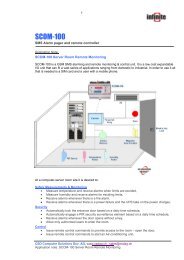
COMPLETE SOLUTION FOR <strong>MONITORING</strong> OF TEMPERATURE,<br />
HUMIDITY AND OTHER QUANTITIES IN THESE FIELDS:<br />
Food and beverages industry (HACCP)<br />
Pharmaceutical industry<br />
Blood stations, pharmacies<br />
Horticulture and cultivation of plants<br />
HVAC (heating, ventilation, air conditioning, cooling<br />
Building and energy management<br />
Research and development<br />
Laboratories (GLP)<br />
Single- to sixteen channel dataloggers are designed for recording of values from transducers of variety of<br />
quantities, alarm state indication, and process control. Parameters of inputs are defined by the types of<br />
installed input modules. Datalogger with transducers configured accordingly to client order can measure<br />
analog signals, frequency, count impulses, evaluate two-state quantities and read data from devices<br />
compatible with ADAM Advantech protocol. If input signal modification is required it is possible to modify the<br />
input modules for different types. Input signals are connected to removable terminal block located on the<br />
logger upper side. Analyzing of the record is enabled after data download to the personal computer by means of<br />
the included program.<br />
<strong>New</strong> firmware and software enable especially to:<br />
get information from the logger by means of the SMS messages - actual values, alarms, memory occupation<br />
and others - as response to SMS request from the user and after alarm creation at the logger. Logger should<br />
be connected via GSM modem supporting SMS.<br />
configure individually each input channel for measurement, alarm evaluation and data logging, including<br />
individual logging interval for each input.<br />
each input channel can be individually programmed for different modes of record (continuous record, time<br />
dependent record, record only if specified logic conditions are matched, record triggered by external signal,<br />
etc.). It is enabled to record with shorter interval in case, measured values match previously defined<br />
conditions e.g. to map in detail trouble state. It is also enabled to memorize actual value and time if defined<br />
time event appears.<br />
set up to four different logic conditions for each channel to activate<br />
alarm. Each condition compares measured values from inputs with<br />
set limits. It is possible to set hysteresis and delay of condition validity.<br />
assign to each input channel name of actual recorded process to<br />
identify monitored object (e.g. type of monitored product). It is<br />
enabled to select this name from logger keyboard during the<br />
operation (<strong>MS3+</strong> and <strong>MS4+</strong>).<br />
indicate alarm state after matching defined combination up to four<br />
alarms from any inputs.<br />
assign each input channel name of currently recorded process to<br />
describe monitored object (e.g. product name). This name is<br />
possible to assign from the <strong>MS3+</strong> or <strong>MS4+</strong> logger front panel keys.<br />
store several configuration profiles (all logger parameters setting)<br />
for different measuring tasks and select profiles from logger<br />
keyboard (<strong>MS3+</strong> and <strong>MS4+</strong>).<br />
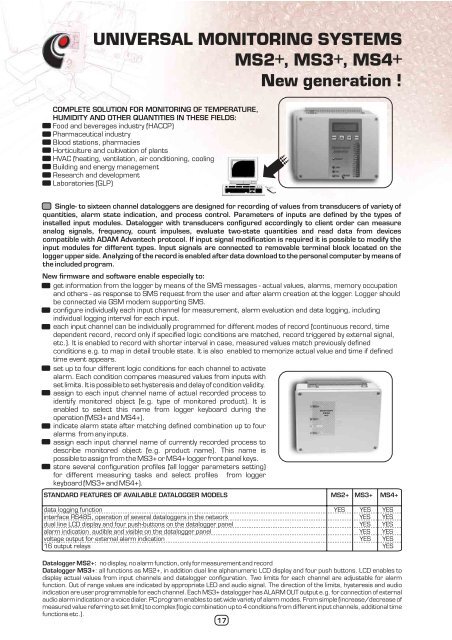
STANDARD FEATURES OF AVAILABLE DATALOGGER MODELS <strong>MS2+</strong> <strong>MS3+</strong> <strong>MS4+</strong><br />
data logging function YES YES YES<br />
interface RS485, operation of several dataloggers in the network YES YES<br />
dual line LCD display and four push-buttons on the datalogger panel YES YES<br />
alarm indication audible and visible on the datalogger panel YES YES<br />
voltage output for external alarm indication YES YES<br />
16 output relays YES<br />
Datalogger <strong>MS2+</strong>: no display, no alarm function, only for measurement and record<br />
Datalogger <strong>MS3+</strong> : all functions as <strong>MS2+</strong>, in addition dual line alphanumeric LCD display and four push buttons. LCD enables to<br />
display actual values from input channels and datalogger configuration. Two limits for each channel are adjustable for alarm<br />
function. Out of range values are indicated by appropriate LED and audio signal. The direction of the limits, hysteresis and audio<br />
indication are user programmable for each channel. Each <strong>MS3+</strong> datalogger has ALARM OUT output e.g. for connection of external<br />
audio alarm indication or a voice dialer. PC program enables to set wide variety of alarm modes. From simple (increase/decrease of<br />
measured value referring to set limit) to complex (logic combination up to 4 conditions from different input channels, additional time<br />
functions etc.).<br />
17
����������������������������<br />
����������������<br />
����������������<br />
Datalogger <strong>MS4+</strong>: all functions as <strong>MS3+</strong> plus installed<br />
board with 16 output relays (250V/8A) with switchitchingover<br />
contacts for controlling of external devices. Each relay can<br />
be switched by appearance of one or more alarms at different<br />
input channels accordingly to setting from the PC program.<br />
Contacts of the relays can control external devices (switching<br />
OFF the device, switching ON the heating or ventilation, switching<br />
ON of distant alarm etc.). Output signals from relays and the<br />
power are connected to internal terminals via cable glands.<br />
PROGRAM FOR PERSONAL COMPUTER<br />
Setting of all system parameters and the stored data processing<br />
is performed by the PC software for Windows. Included<br />
software - freeware is possible to download free from<br />
www.cometsystem.cz.<br />
It enables to communicate with logger<br />
through a serial RS232 link or through an RS485 network (long<br />
distance or more networked loggers), by means of the USB<br />
converter, by means of modems (line or GSM) or by means of<br />
external Ethernet converter. It also enables to configure the<br />
logger, read recorded values and display actual values of the<br />
inputs. It is possible to view and print recorded values in numeric<br />
format and export to dbf format for consequent analysis in any<br />
data processor (e.g. MS Excel). Free program version does not<br />
work with graphs.<br />
Optional software for Windows is also available. Software<br />
has all functions as free software. In addition this software<br />
enables most complex graphic processing of recorded data.<br />
Automatic data reading from logger to PC in preprogrammed<br />
intervals is also possible and other functions.<br />
TECHNICAL PARAMETERS<br />
Memory type:<br />
internal SRAM, backed-up by Lithium battery<br />
Total memory capacity:<br />
2MB (up to 480 000 values)<br />
Logging mode: noncyclic logging stops after filling the memory<br />
cyclic after filling memory oldest data is overwritten by new<br />
Logging interval:<br />
adjustable individually for all input channels from 1 second to 24 hours<br />
Real time clock:<br />
year, leap year, month, day, hour, minute, second, backed-up<br />
by Lithium battery<br />
Input measured values (1 to 16 inputs):<br />
Resolution of the AD converter<br />
are defined for each channel by installed input modules (see table)<br />
accordingly to user requirements<br />
(analog channels):<br />
16 bits, conversion duration approximately 100ms/channel<br />
Interface for communication with computer: RS232 (RxD,TxD,RTS,CTS,GND) direct connection with computer<br />
up to 15 meters, connection with computer by telephone modem,<br />
GSM modem, USB adapter, Ethernet converter<br />
RS485 (only for <strong>MS3+</strong>, <strong>MS4+</strong>) connection with computer up to<br />
1200 m, possibility of connection of several dataloggers to one<br />
communication link<br />
Supported communication speeds:<br />
1200, 9600, 19200, 57600, 115200 Bd<br />
Output for alarm indication<br />
voltage signal 0V/4.8V, maximum current 50mA, output is designed<br />
(only <strong>MS3+</strong>, <strong>MS4+</strong>):<br />
for connection of external audio indication or telephone dialer<br />
Relay alarm outputs (only <strong>MS4+</strong>):<br />
16 relays (max. 8A/250Vac), switching-over contacts<br />
Power:<br />
from external ac/dc adapter, included in delivery<br />
(supplying from source 24V DC possible)<br />
Operating temperature range of datalogger:<br />
0 to 50°C<br />
18
����������������������������<br />
����������������<br />
Dimensions, weight <strong>MS2+</strong>, <strong>MS3+</strong>:<br />
Dimensions, weight <strong>MS4+</strong> (<strong>MS2+</strong>,<strong>MS3+</strong> for<br />
thermocouples):<br />
Protection:<br />
230 x 180 x 90 mm (W x L x D), weight approximately 800g<br />
250 x 320 x 110 mm (W x L x D), weight approximately 2000g<br />
IP20<br />
TYPE MEASURED VALUE<br />
TABLE OF INPUTS<br />
ACCURACY NOTE<br />
A0 dc current 4 to 20 mA ±0.1% FS With source approximately 21V for two<br />
-wire transducers with current loop (e.g.<br />
temperature and humidity transducers<br />
Comet). Only galvanic not isolated.<br />
A1* dc current 4 to 20 mA ±0.1% FS for passive sensing of current<br />
B0* dc current 0 to 20mA ±0.1% FS<br />
B1* dc current 0 to 1A ±0.1% FS<br />
B2* dc current 0 to 5A ±0.1% FS<br />
C0 ac current 0 to 20mA ±1% FS galvanic isolated<br />
C1 ac current 0 to 1A ±1% FS galvanic isolated<br />
C2 ac current 0 to 5A ±1% FS galvanic isolated<br />
D0* dc voltage 0 to 100mV ±0.1% FS<br />
D1* dc voltage 0 to 1V ±0.1% FS<br />
D2* dc voltage 0 to 10V ±0.1% FS<br />
D3* dc voltage 0 to 400V ±0.1% FS<br />
E0 ac voltage 0 to 100mV ±1% FS galvanic isolated<br />
E1 ac voltage 0 to 1V ±1% FS galvanic isolated<br />
E2 ac voltage 0 to 10V ±1% FS galvanic isolated<br />
E3 ac voltage 0 to 400V ±1% FS galvanic isolated<br />
F* measurement of resistance (specify the range) ±0.1% FS two-wire connection<br />
J* input for Nickel RTD temperature sensor<br />
-50 to +100°C ±0.2°C<br />
Ni1000, 6180 ppm/°C, range -50 to +250°C + 100 to +250°C ±0.2%<br />
from reading<br />
K* input for Platinum RTD temperature sensor -140 to +100°C ±0.2°C<br />
Pt100, range -140 to +600°C + 100 to +600°C ±0.2%<br />
from reading two-wire connection<br />
K1* input for Platinum RTD temperature sensor -140 to +100°C ±0.2°C<br />
Pt1000, range -140 to +600°C + 100 to +600°C ±0.2%<br />
from reading two-wire connection<br />
N* thermocouple K (NiCr-Ni)<br />
±(0.3% + 1°C) from<br />
range -70 to +1300°C reading linearized, cold junction compensation<br />
T*<br />
thermocouple T (Cu-CuNi) ±(0.3% + 1°C) from<br />
range -200 to +400°C reading<br />
O* thermocouple J (Fe-Co)<br />
±(0.3% + 1°C)<br />
range -200 to +750°C from reading<br />
P* thermocouple S (Pt10%Rh-Pt),<br />
±(0.3% + 1°C) from<br />
range 0 to +1700°C reading from +200<br />
to +1700°C<br />
Q* thermocouple B (Pt30%Rh-Pt),<br />
±(0.3% + 1°C) from<br />
range +100 to +1800°C<br />
reading from +300<br />
to +1800°C linearized<br />
S* binary input for potential-less contacts maximum resistance of closed contact: 1000 ohms<br />
minimum duration for recording: 200ms<br />
S1 binary voltage input voltage for „switched ON“ state:3 to 30Vdc, input current in<br />
the„switched ON“ state: 1 to 9mA-depending on the applied<br />
voltage, minimum duration for indication of change: 200ms,<br />
galvanic isolated<br />
CTU counter input for voltage signal voltage for „HIGH“ state (for counter status change): 3 to 24Vdc<br />
maximum pulse frequency 5kHz, backed-up operation, galvanic<br />
isolated<br />
CTK counter input for potential-less contacts and maximum pulse frequency 5kHz, programmable filter of pulse<br />
open collector ringing, backed-up operation during power mains failure,<br />
maximum resistance of closed contact: 10 kohms<br />
minimum resistance of open contact: 250 kohms,<br />
galvanic unisolated<br />
FU input for measurement of frequency of<br />
voltage signal<br />
0 to 5kHz, resolution 1Hz, accuracy ±(0.2% from reading + 1Hz)<br />
input voltage for state "H": 3 to 24Vdc<br />
input current in state "H": approximately 7mA<br />
minimum duration of input impuls: 30us, galvanic isolated<br />
19
FK input for measurement of<br />
0 to 5kHz, resolution 1Hz, accuracy ±(0.2% from reading + 1Hz)<br />
frequency of contact switching<br />
maximum resistance of closed contact: 10 kohms<br />
minimum resistance of open contact: 250 kohms,<br />
minimum duration of input pulse: 30us, galvanic unisolated<br />
RS input for serial signal RS485<br />
e.g. measurement from transmitters with RS485 digital output connected to<br />
for devices supporting Advantech protocol the serial RS485 network - ADAM Advantech protocol , galvanic isolated<br />
Notes: Inputs marked (*) are not galvanic isolated and have common ground. These inputs are available also as<br />
galvanic isolated.<br />
Galvanic isolated analog inputs are marked with letter G following the name of input type (e.g. input for passive<br />
measurement of current 4-20mA - type A1 - with galvanic isolation is marked A1G).<br />
Galvanic isolation is not designed<br />
as safety protection. Datalogger for thermocouple measurement has always larger case. Input RS always maps all<br />
channels from its position to position 16. Therefore input RS should always be installed to the position with the highest<br />
input channel number.<br />
INCLUDED ACCESSORY: Calibration certificate from the manufacturer,<br />
ac/dc adapter, wall holders,<br />
communication cable for RS232 of 2 meters length, free program for Windows (also ready to download from<br />
www.cometsystem.cz).<br />
Program enables to control all logger functions and view and print the record in numerical<br />
format.<br />
OPTIONAL ACCESSORY:<br />
M2006 - built-in converter for communication with the PC via USB port - only for new <strong>MS3+</strong>, <strong>MS4+</strong><br />
MP001 - RS485/RS232 converter for<br />
serial port COMx of the PC, ac/dc adapter included<br />
M2002 - external audio indication unit<br />
MP002 - telephone voice dialer for alarm reporting, ac/dc adapter included<br />
SWR006 - optional software for Windows comfort graphic environment, including on-line graph<br />
M2007 - built-in Ethernet interface for communication via Ethernet - only for new <strong>MS3+</strong>, <strong>MS4+</strong><br />
MP010 - built-in independent interface for sending and reception of SMS<br />
MP009 - GSM modem Fastrack M1306B, without accessories<br />
MP009/1 - GSM antenna 3dB for modem Fastrack, right-angled<br />
MP009/2 - Data cable for setting of GSM modem Fastrack<br />
MP009/3 - Ac/dc source 230V/12V for powering of GSM modem Fastrack<br />
Watertight unit - in larger case with cable glands with protection rate IP55 - only for <strong>MS2+</strong>, <strong>MS3+</strong>.<br />
Not available for loggers with thermocouple inputs and <strong>MS4+</strong>. Case dimensions 250 x 320 x 110 mm.<br />
Warranty: 2 years<br />
����������������������������<br />
����������������<br />
Temperature and humidity transducers Comet are directly compatible with the <strong>MS2+</strong>, <strong>MS3+</strong>, <strong>MS4+</strong> systems.<br />
It is very easy to built a complete calibrated temperature and/or relative humidity monitoring system with<br />
Comet components.<br />
20