Sensor Installation Handbook Preface 3rd edition - Siemens ...
Sensor Installation Handbook Preface 3rd edition - Siemens ...
Sensor Installation Handbook Preface 3rd edition - Siemens ...

You also want an ePaper? Increase the reach of your titles
YUMPU automatically turns print PDFs into web optimized ePapers that Google loves.
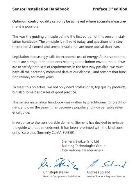
<strong>Sensor</strong> <strong>Installation</strong> <strong>Handbook</strong> <strong>Preface</strong> 3 rd <strong>edition</strong><br />
Optimum control quality can only be achieved where accurate measurement<br />
is possible.<br />
This was the guiding principle behind the first <strong>edition</strong> of this sensor installation<br />
handbook. The principle is still valid today, and questions of instrumentation<br />
& control and sensor installation are more topical than ever.<br />
Legislation increasingly calls for economic use of energy. At the same time,<br />
there are stringent requirements relating to the indoor environment. If we<br />
are to satisfy both sets of requirements in the best way possible, we must<br />
have all the necessary measured data at our disposal, and sensors that func -<br />
tion reliably for many years.<br />
To meet this objective, we not only need professional, top quality products,<br />
but also some basic rules of good practice.<br />
This sensor installation handbook was written by practitioners for practitioners,<br />
and over the years it has become a popular and indispensable refer -<br />
ence guide.<br />
In response to the considerable demand, <strong>Siemens</strong> has decided to re-issue<br />
the guide without amendment. It has been re-printed with the kind consent<br />
of suissetec (formerly CLIMA-SUISSE).<br />
<strong>Siemens</strong> Switzerland Ltd<br />
Building Technologies Group<br />
International Headquarters<br />
Christoph Bleiker Andreas Soland<br />
Head of Components Subdivision Head of Product Segment <strong>Sensor</strong>s
<strong>Sensor</strong> <strong>Installation</strong> <strong>Handbook</strong> <strong>Preface</strong> 2 nd <strong>edition</strong><br />
To the reader<br />
We have participated with enthusiasm in the work on the second <strong>edition</strong> of<br />
this "<strong>Sensor</strong> <strong>Installation</strong>" guide. The subject matter is of particular relevance<br />
to our association because, with the help of our members, we are in a position<br />
to set the right course and define good practice.<br />
We are sending you the revised and extended guide in the current format,<br />
which consists, as before, of a printed version for installers on site. This<br />
now also includes a CD-ROM for reference at home or in the office.<br />
Diagrams or whole sections can be printed from this CD and used as a<br />
mounting guide.<br />
The same team of writers once again gave their time unstintingly to update<br />
this guide for practitioners and by practitioners, to reflect the state of the<br />
art. Here, we would like to express our sincere thanks to all those who have<br />
contributed in one way or another to the drafting and production of the<br />
handbook.<br />
We have no doubt that the <strong>Sensor</strong> <strong>Installation</strong> <strong>Handbook</strong> meets the real<br />
needs of our corporate members and of the building services industry in<br />
general.<br />
CLIMA-SUISSE<br />
Verband Schweizerischer und Liechtensteinischer<br />
Heizungs- und Lüftungsfirmen<br />
(Association of heating & ventilation companies in Switzerland<br />
and Liechtenstein)<br />
Lucius Dürr Bernhard Fischer<br />
Director Manager<br />
Technology, Energy, Environment
<strong>Sensor</strong> <strong>Installation</strong> <strong>Handbook</strong> <strong>Preface</strong> to the first <strong>edition</strong><br />
To the reader<br />
A control system is only as good as the sensor used to measure the controlled<br />
variable (temperature, humidity, pressure etc.) and transmit it as a measured<br />
value to the controller. It is crucial that the sensor should provide an<br />
accurate measurement of the controlled variable at the reference point in<br />
the control loop. However, it is often found in practice that too little atten -<br />
tion has been paid both to the way in which the sensor is mounted, and to<br />
its location. This generally results in a failure to meet the desired conditions<br />
satisfactorily, and this, in turn, can lead to customer complaints.<br />
The Swiss controls companies Landis & Gyr Building Control (Schweiz) AG,<br />
Steinhausen, Fr. Sauter AG, Basle, and Staefa Control System AG, Stäfa,<br />
decided some time ago to contribute towards better control engineering by<br />
producing a "<strong>Sensor</strong> <strong>Installation</strong>" handbook. Thanks to the active involvement<br />
of Sulzer Infra (Schweiz) AG, Zurich, the handbook incorporates practical<br />
expertise from experienced system contractors.<br />
While "<strong>Sensor</strong> <strong>Installation</strong>" is written for the benefit of engineers and installers<br />
on site, it will also provide the project engineer with useful information<br />
at the design stage. It is written by practitioners for practitioners, but also<br />
makes a contribution to energy optimisation.<br />
The writers hope that this booklet fulfils the aims described.<br />
Landis & Gyr<br />
Building Control (Schweiz) AG<br />
Best regards,<br />
Fr. Sauter AG, Basle Staefa Control System AG Sulzer Infra (Schweiz) AG<br />
Zurich
Authors:<br />
René Bader<br />
Director of Training<br />
Fr. Sauter AG, 4016 Basle<br />
Willy Landolt<br />
<strong>Siemens</strong> Building Technologies (Schweiz) AG<br />
Ewald Senn<br />
Formerly of: Sulzer Infra (Schweiz) AG<br />
Paul Züger<br />
Central Branch Manager<br />
<strong>Siemens</strong> Building Technologies (Schweiz) AG<br />
English translation by Marguerite Minster and Gerald McGilley<br />
<strong>Siemens</strong> plc<br />
Building Technologies Group (UK)
General notes for all sensors<br />
Always observe local installation<br />
and safety regulations.<br />
Do not install sensors so that they protrude in<br />
any direction, and do not suspend them below<br />
the horizontal.<br />
Ensure that they are protected against damage<br />
and vandalism and will not cause injury.<br />
Be aware of the effects of orientation on the<br />
functioning of the sensor.<br />
Always determine the following before mounting:<br />
■ Min./max. ambient temperature<br />
■ Ambient humidity and exposure to<br />
spray water<br />
■ Exposure to vibration<br />
■ Explosion protection<br />
■ External influences<br />
General notes for all sensors<br />
1
General notes for all sensors<br />
2<br />
Take account of the active and inactive sections<br />
of a sensor probe.<br />
A tight-sealing test-hole must be provided adjacent<br />
to every sensor.<br />
The cable should be installed with a "drip loop"<br />
to prevent water from entering the sensor<br />
housing.
Always allow a sufficient length of spare<br />
cable so that the sensor can be removed<br />
at any time without disconnecting the wiring.<br />
When installing a sensor, avoid compressing the<br />
lagging.<br />
Use a graduated-diameter mounting<br />
flange to avoid compressing the lagging.<br />
If the mounting flange supplied does not have<br />
the appropriate graduations, use spacing bushes<br />
to avoid compressing the lagging.<br />
General notes for all sensors<br />
3
General notes for all sensors<br />
4<br />
If the sensors are to be concealed (e.g. in false<br />
ceilings, shafts etc.), mark their locations visibly<br />
and record them in the site documentation.<br />
Fix a labelling plate in the direct vicinity of the<br />
sensor. This must include a plain text description<br />
and the reference number, which appears in the<br />
plant schematic. Do not attach the label to the<br />
device itself.
Temperature Immersion sensors · Water<br />
Ensure that the full active length of the sensor<br />
is immersed in the medium.<br />
Incorrect installation<br />
Temperature · Immersion sensors<br />
5
Temperature · Immersion sensors<br />
6<br />
Plastic sleeve<br />
Chilled water and refrigeration pipes<br />
To prevent condensation, extend the immersion pocket inside the lagging<br />
by use of a plastic sleeve.
Water-resistant seal<br />
Chilled water and refrigeration pipes<br />
The hole in the lagging must be sealed, to prevent the ingress of moisture<br />
(water-resistant seal).<br />
Temperature · Immersion sensors<br />
7
Temperature · Immersion sensors<br />
8<br />
Install sensors against the direction of flow.<br />
Incorrect installation<br />
Install at the correct angle.
If the active length (a) of the sensor probe is<br />
longer than the diameter of the pipe, the sensor<br />
should be installed diagonally, or in a bypass<br />
pipe or bend.<br />
The inlet side of the bypass pipe should<br />
project into the main pipe.<br />
Temperature · Immersion sensors<br />
9
Temperature · Immersion sensors<br />
10<br />
Maintain a clearance (distance A) between the<br />
sensor and any obstruction, so that there is<br />
room to remove the sensor from the immersion<br />
pocket.<br />
For each sensing point, an additional immersion<br />
pocket, adjacent to the sensor, must be provided<br />
for test purposes.<br />
Install outlet-temperature sensors directly at the<br />
heat exchanger outlet.
<strong>Sensor</strong>s mounted without immersion pockets or<br />
with slotted or perforated immersion pockets<br />
must be identified accordingly.<br />
Attach a label marked:<br />
Installed without immersion pocket.<br />
Distance from mixing point to sensor<br />
minimum 10 x d<br />
maximum 15 x d<br />
Distance from mixing point to sensor<br />
minimum 10 x d<br />
maximum 15 x d<br />
When mixing water at different temperatures,<br />
always maintain an adequate distance between<br />
the mixing point and the sensor (to take account<br />
of stratification).<br />
Label<br />
Installed without<br />
immersion pocket<br />
Temperature · Immersion sensors<br />
11
Temperature · Cable sensors<br />
12<br />
Temperature Cable sensors · Water<br />
The sensor element is not affected by orien -<br />
tation, but must be fully immersed in the<br />
medium to be measured (air or water).<br />
Use a file to ensure a smooth, clean contact<br />
surface, and fill the space between the sensor<br />
and the pipe with heat-conductive compound<br />
to improve thermal conductivity.
Temperature Probe sensors · Air<br />
Ensure that the full length of the sensor probe is<br />
exposed to the air flow.<br />
A test hole must be provided adjacent to every<br />
sensor.<br />
Do not use probe-type sensors in areas where<br />
stratification can occur (e.g. downstream of<br />
mixing dampers, heating coils, cooling coils or<br />
heat recovery units). Averaging sensors should<br />
be considered.<br />
Temperature · Probe sensors<br />
13
Temperature · Capillary sensors<br />
14<br />
Temperature Capillary sensors with probes<br />
wrong ➞<br />
right ➞<br />
Install so that the device head is higher than<br />
the sensor probe.<br />
The sensor probe should be tilted downwards.
The ambient temperature at the device head<br />
must always be higher than the temperature<br />
to which the sensor probe is exposed.<br />
The sensor element must always point<br />
downwards.<br />
Do not allow the capillary to form a U-shape.<br />
Do not bend the capillary too tightly<br />
(radius of bend must not be less than 50 mm).<br />
When routing the capillary through internal or<br />
external walls, for example, always use a lined<br />
and insulated conduit.<br />
Temperature · Capillary sensors<br />
15
Temperature · Capillary sensors<br />
16<br />
Any unused length of capillary should be neatly<br />
rolled.<br />
Where the capillary passes through sheet metal,<br />
protect it with a rubber grommet<br />
(to prevent shearing).
Temperature Averaging sensors<br />
Allow a distance of at least 50 mm between the<br />
heat exchanger and the sensor.<br />
The entire length of an averaging sensor must<br />
be installed fully inside the air duct.<br />
The sensor element must be distributed evenly<br />
over the full cross-section.<br />
Temperature · Averaging sensors<br />
17
Temperature · Averaging sensors<br />
18<br />
If air washers are used for humidification, install the sensor element<br />
downstream of the eliminator plate, in the direction of air flow.
Do not bend the capillary too tightly<br />
(radius of bend must not be less than 50 mm).<br />
When routing the capillary through internal or<br />
external walls, for example, always use a lined<br />
and insulated conduit.<br />
Where the capillary passes through sheet metal,<br />
protect it with a rubber grommet<br />
(to prevent shearing).<br />
Install the sensor element using capillary<br />
supports.<br />
Temperature · Averaging sensors<br />
19
Temperature · Frost protection<br />
20<br />
Temperature Frost protection · Air<br />
Leave a spare capillary loop of 20 cm so that<br />
functioning can be tested outside the unit.<br />
If the supply ductwork is outdoors or in an<br />
unheated space, then both the measuring head<br />
and the test loop of the thermostat must be<br />
located inside the duct and downstream of the<br />
heat exchanger.<br />
Install the capillary in the direction of air flow,<br />
downstream of the first water-filled heating coil<br />
exposed to frost.<br />
The capillary must be installed diagonal to the<br />
heat-exchanger pipes.
When installing on "drawer"-type units, ensure<br />
that the electrical connections are long enough<br />
to enable the units to be pulled out.<br />
If a water-filled cooling coil is installed upstream<br />
of the first heat exchanger, then the frost protection<br />
thermostat must be installed upstream of<br />
the cooling coil, in the direction of the air flow.<br />
With large heat exchangers, or with heat<br />
exchangers comprising several units, more<br />
than one frost thermostat must be installed<br />
(minimum 1 per unit).<br />
Temperature · Frost protection<br />
21
Temperature · Frost protection<br />
22<br />
Do not bend the capillary too tightly<br />
(radius of bend must not be less than 50 mm).<br />
When routing the capillary through internal or<br />
external walls, for example, always use a lined<br />
and insulated conduit.<br />
Where the capillary passes through sheet metal,<br />
protect it with a rubber grommet<br />
(to prevent shearing).<br />
Any unused length of capillary should be neatly<br />
rolled.
Use spacing clips to maintain a 50 mm<br />
clearance.<br />
Install the sensor element using capillary<br />
supports.<br />
Temperature · Frost protection<br />
23
Temperature · Room<br />
24<br />
Temperature Room sensors<br />
Install sensors at a height of 1.5 m in occupied<br />
spaces, and at least 50 cm from the adjacent<br />
wall.<br />
Do not install where sensor will be exposed to<br />
direct solar radiation.<br />
Always use a thermally-insulated backing when<br />
fitting to solid walls (steel, concrete etc.)
Do not install on external walls.<br />
Avoid recesses (e.g. shelving) and alcoves.<br />
Do not install near lamps or above radiators.<br />
Avoid chimney walls.<br />
Temperature · Room<br />
25
Temperature · Room<br />
26<br />
Do not install directly adjacent to doors.<br />
Do not install behind curtains.<br />
Do not fit to walls concealing hot-water pipes.<br />
Seal gaps between cable/plastic tubing and<br />
conduit. Otherwise measurements will be<br />
falsified by incorrect circulation of the air.
Temperature Outdoor sensors<br />
The system design determines the façades<br />
(N,S,E,W) on which the sensor should be<br />
located.<br />
Do not expose to direct solar radiation.<br />
Do not install on façades affected by significant<br />
rising heat.<br />
Do not install on façades warmed by solar<br />
radiation.<br />
Temperature · Outdoor<br />
27
Temperature · Outdoor<br />
28<br />
Avoid chimney walls.<br />
Do not install under eaves.<br />
Do not install above windows.<br />
Do not install above ventilation shafts.
Seal gaps between cable/plastic tubing and<br />
conduit.<br />
Otherwise measurements will be falsified by<br />
incorrect circulation of the air.<br />
Do not paint the sensor.<br />
Ensure accessibility (for inspection/testing)<br />
Temperature · Outdoor<br />
29
Temperature · Outdoor<br />
30<br />
Temperature Outdoor sensors · Cable sensors<br />
The same rules apply to outdoor cable sensors<br />
as to any other outdoor sensors. The cable<br />
should be connected from below (to protect it<br />
from dripping water).
Temperature Surface-mounted strap-on sensors<br />
The surface must be clean and smooth (remove<br />
paint). The sensor must be fixed firmly to the<br />
surface. Use heat-conductive compound.<br />
Important:<br />
Avoid exposure to external heat gains.<br />
Consider cable length when fitting to windows<br />
which can be opened!<br />
The sensor must be fixed directly to the window<br />
surface.<br />
The sensor must be fixed directly to the surface.<br />
Use heat-conductive compound.<br />
Temperature · Surface<br />
31
Temperature · Surface<br />
32<br />
Distance from mixing point to sensor<br />
Minimum 10 x d<br />
Maximum 15 x d<br />
Distance from mixing point to sensor<br />
Minimum 10 x d<br />
Maximum 15 x d<br />
When mixing water at different temperatures, always maintain an<br />
adequate distance between the mixing point and the sensor<br />
(to take account of stratification).
Temperature Wind sensors<br />
Install on the façades exposed to the main wind<br />
direction.<br />
Make sure the sensor is accessible<br />
(for inspection/testing).<br />
Do not install under eaves.<br />
Do not install in recesses.<br />
Temperature · Wind<br />
33
Temperature · Solar<br />
34<br />
Temperature Solar sensors<br />
Install solar sensors on the façades behind<br />
which the associated control system is opera -<br />
tive.<br />
Install the sensor where it is easily<br />
accessible (for inspection/testing).
Avoid shade (from trees or neighbouring<br />
houses etc.)<br />
Temperature · Solar<br />
35
Humidity · Duct<br />
36<br />
Humidity Duct sensors<br />
Note that humidity sensors are affected by air<br />
velocity. The air velocity in the vicinity of the<br />
sensor must not exceed 10 m/sec.<br />
Precaution: Fit the sensor with a perforated<br />
shield or cover (e.g. perforated steel)<br />
Avoid dead-legs. (Supersaturation can<br />
occur in areas where there is no air flow.)<br />
Important:<br />
When installing sensors in ducts with negative<br />
pressure, it is possible for air from an external<br />
source to be drawn into the device and the<br />
installation hole.<br />
(Seal tightly to prevent false readings.)
A test hole must be provided for every humidity<br />
sensor (downstream of the sensor).<br />
Recommended diameter: 40 mm.<br />
For maintenance purposes, the electrical<br />
connections should be of the plug-in type<br />
(e.g. TT45…).<br />
Humidity · Duct<br />
37
Humidity · Duct<br />
38<br />
Distance for humidification measurements for BM BM is the distance between the humidifier and the humidity sensor necessary<br />
to allow the air to absorb 100% of the water supplied. The required<br />
distance depends on the amount of water supplied, the velocity of the air<br />
and the type of humidifier system.<br />
If the humidity sensor is not mounted at the required distance, it will<br />
produce a false reading.<br />
Example: Because it is in the wrong position, the sensor here measures<br />
only 30% of the water or steam introduced into the system, as only this<br />
amount has been fully absorbed in gaseous form into the air. The sensor<br />
element will get wet, produce an incorrect reading, and may be damaged.<br />
Humidification systems:<br />
Air washers B M downstream of eliminator plate<br />
Tray-type humidifier B M 3.5 m<br />
Spray rehumidifiers B M 5.5 m<br />
Spray humidifiers See water volume diagram (adiabatic) page 39<br />
Ultrasound humidifiers<br />
Centrifugal humidifiers<br />
Atomizer humidifiers<br />
see diagram for steam page 40<br />
Pressurized steam B M = Isotherm<br />
“Pressure-free” steam B M = Isotherm · 1.3
Distance for adiabatic humidification<br />
measurements<br />
This diagram is designed for use in winter, with<br />
an absolute humidity content of 1.5 g/kg on the<br />
intake side, and a supply air temperature of<br />
18 °C.<br />
Water chart (adiabatic)<br />
Air velocity in the duct or device w (m/s)<br />
Distance for humidification measurements B M (m)<br />
Method: Enter the air velocity (in m/s) on the left edge of the diagram (e.g.<br />
2.0 m/s). From this point, draw a line to the right, along the line indicating<br />
the increase in humidity (example: � x = 10 g/kg).<br />
Starting where the two lines intersect, draw a vertical line and read the<br />
required distance B M for humidification measurements on the horizontal line<br />
at the bottom of the diagram (6.7 m).<br />
Water volume Δ x (g/kg)<br />
Humidity · Duct<br />
39
Humidity · Duct<br />
40<br />
Determining B M<br />
Distance for humidification<br />
measurement B M (m) = 8.5<br />
Distance B M for humidification measurements<br />
with steam humidifiers<br />
A certain distance is required between humidifier<br />
and sensor, so that the air has time to absorb the<br />
water (vapour) supplied by the humidifier before<br />
the sensor measures the humidity. This distance<br />
is marked on the diagram as B M. The minimum distance<br />
between the humidifier and the humidity<br />
sensor must be equivalent to at least B M.<br />
Air velocity in duct or device w (m/s)<br />
Increase<br />
in air humidity � x [g/kg]<br />
Method: Enter the increase in humidity in g water/kg air (e.g. 4.5 g/kg) on<br />
the right edge of the diagram.<br />
Draw a horizontal line extending from this point towards the left.<br />
Enter the minimum duct air velocity (in m/s) on the bottom edge of the<br />
diagram (e.g. 1.9 m/s) and draw a vertical line extending upwards from<br />
this point.<br />
From the point of intersection of these two lines, draw a diagonal line extending<br />
upwards and parallel to the existing diagonals. Read the distance,<br />
B M, in metres, from the scale on the edge of the diagram (example 8.5 m).
Humidity sensor<br />
Average humidity measurement<br />
Locating the humidity sensor in a bypass duct improves the measurement<br />
of average, relative or absolute humidity, and should be used:<br />
In cases of temperature or humidity stratification.<br />
Here too, the appropriate distance for humidity measurements, B M, must be<br />
maintained.<br />
Humidity · Duct<br />
41
Humidity · Room<br />
42<br />
Humidity Room sensors<br />
H%<br />
Install sensors at a height of 1.5 m in occupied<br />
spaces, and at least 50 cm from the adjacent<br />
wall.<br />
Do not install where sensor will be exposed to<br />
direct sunlight.<br />
Do not install on external walls.
Seal gaps between cable/plastic tubing and<br />
conduit.<br />
Otherwise measurements will be falsified by<br />
incorrect circulation of the air.<br />
Do not install near lamps or above radiators.<br />
Avoid chimney walls.<br />
Do not install directly adjacent to doors.<br />
Humidity · Room<br />
43
Pressure · General<br />
44<br />
Pressure General<br />
Pressure sensors are affected by orientation<br />
(see manufacturer's installation instructions).<br />
Pressure tubes must be provided with an<br />
isola table T-fitting near the device head for<br />
test purposes.<br />
To prevent overload on one side when making<br />
adjustments, the connection must always be<br />
fitted with an isolating bypass.
Where there is a risk of condensation, the differential<br />
pressure tube must be installed at a gradient<br />
of 1:30 and fitted with a drain mechanism.<br />
The drainage point must be lower than the de -<br />
vice head and sensing point. Protect from frost<br />
and avoid U-shapes.<br />
Pressure tubes containing circulating air must<br />
not be introduced into the open air or routed<br />
through cold rooms or ducts.<br />
This prevents the risk of condensate freezing in<br />
the tubes (e.g. with pneumatic venting sensors).<br />
Mount on a vibration-free surface.<br />
The pressure-tapping point must not be located<br />
in turbulent air. Ensure sufficiently long settlingzones<br />
upstream and downstream of the tapping<br />
point.<br />
A settling-zone consists of a straight section of<br />
pipe or duct, with no obstructions. Formula:<br />
dg = Equivalent diameter<br />
Pressure · General<br />
45
Pressure · Air<br />
46<br />
Pressure Air<br />
The measuring tip is screwed or glued to the<br />
duct wall.<br />
Seal to protect from external air. Remove any<br />
swarf from the inside of the duct.<br />
Important<br />
Protruding fixing screws will impair correct<br />
measurement.<br />
Correct installation.
Avoid using tips which protrude into the duct<br />
for static pressure measurements.<br />
Probes are used to measure static pressure in<br />
the duct. Must be installed parallel to the flow<br />
and either with the flow or against it.<br />
Internal<br />
diameter mm<br />
Length of tube (m)<br />
Sizing the pressure tubes (“measuring tubes”)<br />
for air and gases: Keep the tube as short as possible.<br />
An internal diameter of 4 mm is sufficient for pressure tubes of up to two<br />
metres in length. For longer pressure tubes, the internal diameter should<br />
be as indicated in the diagram.<br />
(Example: A pressure tube of 6 m requires an internal diameter of 6 mm.)<br />
Pressure · Air<br />
47
Pressure · Air<br />
48<br />
Connect the sensor and measuring instrument<br />
to the same point.<br />
The tapping point must not be located where it<br />
will be affected by obstructions to the flow.
Where more than one sensor is used, the sensors<br />
should be installed on the same plane in<br />
the flow, and not in a position where one device<br />
will obstruct the air flow to the other.<br />
dg = Equivalent diameter, page 45<br />
Leave sufficient clearance downstream of any<br />
obstacles.<br />
Pressure · Air<br />
49
Pressure · Room<br />
50<br />
Pressure Room<br />
Pressure Outside air<br />
The end of the pressure tube leading into the<br />
room should be protected by an air-permeable<br />
cover.<br />
Seal gaps between cable/plastic tubing and<br />
conduit. Otherwise measurements will be<br />
falsified by incorrect circulation of the air.<br />
Pressure Suction<br />
Measure the outdoor pressure in an area sheltered from wind. Individual<br />
façades are not suitable measurement locations, as the pressure varies according<br />
to the wind direction.<br />
The correct location for measurement is a place where the air can circulate<br />
freely, such as a flat roof. Note, however, that the sensing point must be<br />
fitted with a wind shield.<br />
Options:<br />
Calculate average based on pressure measurements<br />
taken on several façades.<br />
Measure pressure in an open space<br />
(min 1.5 m above ground level).<br />
Multiple sensing point on flat roof.
Pressure Liquids<br />
Pressure tapping point:<br />
Sensing hole: diameter 5 mm, drilled and<br />
deburred.<br />
Smooth interior (no burrs).<br />
Use a damping coil to avoid transferring vibra -<br />
tions. Bend a 1 m long copper pipe, 4…6 mm in<br />
diameter, into a spiral with loops with a diameter<br />
of 15 cm.<br />
Wrong:<br />
Air bubbles and condensate remain trapped.<br />
Pressure · Liquids<br />
51
Pressure · Liquids<br />
52<br />
Wrong:<br />
Condensate cannot be drained.<br />
<strong>Installation</strong> in conjunction with liquids:<br />
Always install the pressure sensor in a location<br />
which is lower than the sensing point.<br />
<strong>Installation</strong> in conjunction with vapours/gases<br />
Always install the pressure sensor in a location<br />
which is higher than the sensing point.
Pressure measurement in conjunction<br />
with liquids<br />
Do not measure at the top of the pipe (trapped<br />
air or air bubbles) or at the bottom (dirt).<br />
The correct location for a sensing point is at<br />
the side.<br />
Condensing gases<br />
Measure at the top to prevent condensate from<br />
entering the pressure tube.<br />
Pressure · Liquids<br />
53
Flow velocity · Air<br />
54<br />
Flow velocity Air<br />
Formula:<br />
dg = Equivalent diameter<br />
The pressure-tapping point must not be located<br />
in turbulent air. Ensure sufficiently long settling-zones<br />
upstream and downstream of the<br />
tapping point.<br />
A settling-zone consists of a straight section of<br />
pipe or duct, with no obstructions.<br />
Fan-belt monitoring<br />
The differential pressure across the fan is only<br />
suitable for fan-belt monitoring.<br />
■ Negative connection (–) on suction side<br />
use copper tube<br />
■ Positive connection (+) on discharge side:<br />
use Pitot tube<br />
Flow monitoring<br />
Flow detectors (electrothermal)<br />
Electrothermal flow detectors must be installed<br />
in a zone with a high flow velocity, e.g. where<br />
pipes narrow.<br />
Differential pressure<br />
Do not monitor flow or differential pressure<br />
where flow resistance is variable, e.g. at filters,<br />
cooling coils, fans etc. Suitable locations:<br />
heating coils, silencers, baffles, attenuators.
Flow monitoring Water<br />
Correct installation<br />
If differential pressure is used to monitor the flow, it is important to ensure<br />
that there are no stop valves or balancing valves between the sensing<br />
points.<br />
Incorrect installation<br />
Flow monitoring · Water<br />
55
Air quality · Room<br />
56<br />
Air quality sensors Room sensors<br />
There are two types of air quality sensors:<br />
Mixed gas (or VOC) sensors<br />
The accumulation of up to 24 different gases is<br />
measured in the ambient air (total concentra -<br />
tion measured)<br />
Selective gas sensors<br />
These measure only one gas (e.g. CO 2) in the<br />
ambient air (selective measurement).<br />
Do not locate temperature or humidity sensors<br />
above or below the AQ sensor.<br />
The heated sensor element produces significant<br />
intrinsic heat in the device. Owing to this characteristic,<br />
the room temperature or room humidity<br />
must not be measured in the immediate vicinity.<br />
Maintain a clearance of minimum 60 mm on<br />
each side of the AQ sensor.<br />
CO2 sensors<br />
Selective gas sensors may require maintenance<br />
at regular intervals. Please consult the manufacturer’s<br />
instructions. The sensor must be installed<br />
in an accessible location.
Avoid recesses (e.g. shelving) and alcoves.<br />
Do not install directly adjacent to doors.<br />
Do not install behind curtains.<br />
Seal gaps between cable/plastic tubing and<br />
conduit. Otherwise measurements will be<br />
falsified by incorrect circulation of the air.<br />
Air quality · Room<br />
57
Liquid level<br />
58<br />
Liquid level sensing<br />
A distinction is made between the following methods:<br />
■ Capacitive measuring probes<br />
■ Pressure/differential pressure (hydrostatic)<br />
■ Ultrasound<br />
■ Tank weighing systems<br />
■ Electromechanical sensing<br />
Atmospheric<br />
pressure<br />
Measured<br />
variable<br />
Pressure detector<br />
measures liquid<br />
level<br />
Compressed<br />
air<br />
Measured<br />
variable<br />
Pressure measurement:<br />
The pressure is defined by the height of the liquid<br />
medium, measured from the sensor to the<br />
surface of the liquid. There are no critical factors<br />
to consider when installing the pressure sensor.<br />
The sensor material must be suitable for use<br />
with the liquid medium.<br />
Bubble technique:<br />
The pressure measurement is determined by the<br />
height of the liquid above the bubble-tube<br />
outlet.
Floats:<br />
These are used in open and sealed systems.<br />
The device head must be installed above<br />
the maximum expected liquid level.<br />
Tank weighing system<br />
The measured result is determined by the tank<br />
content (mass weight).<br />
The sensor should be mounted in accordance<br />
with the manufacturer's instructions.<br />
Capacitive measuring probes:<br />
These are used in open and sealed tanks.<br />
Mounting: The distance from the next electri -<br />
cally conductive component must be as<br />
specified by the manufacturer.<br />
Conductance systems:<br />
These are used in open and sealed tanks.<br />
The measured result is determined by the length<br />
of the immersed electrodes.<br />
Mounting: The distance from the next electri -<br />
cally conductive component must be as<br />
specified by the manufacturer.<br />
Liquid level<br />
59
Liquid level<br />
60<br />
Location<br />
of sensor<br />
Magnetic level switches:<br />
These are used in open and sealed tanks.<br />
Mounting:<br />
The liquid-level tube and the location of the<br />
level switch are determined by the manufac -<br />
turer. Level switches are installed at the same<br />
height as the required liquid level.<br />
Hydrostatic level sensing:<br />
The measurement is based on the maximum<br />
liquid level and the location of the sensor.
Principles of operation<br />
General<br />
All measuring systems transmit physical variables such as temperature,<br />
humidity, pressure etc. with a particular response characteristic.<br />
The “response characteristic” (e.g. Tt = dead time / T = time constant or<br />
“lag”) refers to the reactions of the measuring systems.<br />
Transfer with dead time, Tt, e.g. mixed-water temperature<br />
As the valve is adjusted by a given stroke, the temperature of the mixed<br />
water in the valve changes without any time delay.<br />
However, the valve and the temperature sensor are some distance apart.<br />
This is the distance the mixed water has to travel before the sensor can<br />
detect the change.<br />
This “transportation time” is referred to as “dead time”.<br />
Tt = Dead time<br />
Principles of operation<br />
61
Principles of operation<br />
62<br />
Time constant of measuring sensors in liquids<br />
For measuring or acquiring medium temperatures in piping systems,<br />
sensors are usually installed with protection pockets. These pockets<br />
represent the first delay element in the measuring process, the air gap<br />
between pocket and sensing element the second. The third delay<br />
element is the sensor’s time constant. Of these three delays in series,<br />
that of the air gap between pocket and sensing element is the greatest<br />
since the heat conductivity of air is poor. This poor transmission of<br />
heat from the medium to the sensing element can be considerably<br />
improved by filling the air gap with oil or glycerin.<br />
If glycerin is used, the welded protection pocket must be inclined.<br />
Transfer with time constant = T<br />
No sensors transmit the change in a measured variable instantaneously.<br />
The delay in transmission time (the time constant, or “lag”, T) can be shown<br />
in diagrammatic form.<br />
Change in measured variable<br />
Time constant T<br />
The time taken to transmit 63% of the total change in the measured<br />
variable is referred to as the time constant, T.<br />
It takes a period equivalent to five times the time constant to transmit<br />
approximately 99% of the change in measured variable.
Example of response characteristic<br />
Contact fluid<br />
<strong>Sensor</strong> in pipe<br />
Output signals<br />
The sensor converts the measured variable into an output signal.<br />
<strong>Sensor</strong>s (measuring devices) are divided on the basis of their output<br />
signals into two main categories:<br />
Switching devices, examples:<br />
Thermostats, hygrostats, pressure switches<br />
<strong>Sensor</strong> in water without immersion pocket<br />
63 %<br />
1,6 sec<br />
<strong>Sensor</strong> in immersion pocket with contact fluid<br />
63 %<br />
16 sec<br />
<strong>Sensor</strong> in immersion pocket without contact fluid<br />
60 sec<br />
Stepless (continuously variable) signals, examples:<br />
Temperature sensors, humidity sensors, pressure sensors<br />
63 %<br />
Principles of operation<br />
63
Principles of operation<br />
64<br />
Switching devices<br />
On/off<br />
Changeover<br />
3-position<br />
Multi-stage<br />
Dynamic switching differential<br />
Setpoint<br />
Switching devices<br />
Thermostats<br />
Hygrostats<br />
Pressure switches<br />
Where a switching device such as a thermostat is installed in a system,<br />
it should be noted that the temperature swing will be wider than the<br />
switching differential of the thermostat. The thermostat operates at the<br />
switching points specified in the data sheet (static switching differential),<br />
but the inertia of the system (residual heat, dead time etc.) causes the controlled<br />
variable to overshoot or undershoot. The finally measurable temperature<br />
swing (the dynamic switching differential) will therefore always be<br />
wider than the static switching differential of the thermostat.
Stepless devices<br />
Stepless devices (sensors) produce a continuously variable, or “stepless”<br />
output signal. A given output value is assigned to each measured variable<br />
(temperature, humidity, pressure etc.) and the output signals are<br />
standardized.<br />
Normally, pressure, current, voltage or resistance signals are used for<br />
this purpose.<br />
Pneumatic control system<br />
Pressure output signal: 0.2 ... 1.0 bar<br />
Measured variable<br />
<strong>Sensor</strong>s used in electronic control systems operate with various output<br />
signals.<br />
Output signal Output signal Output signal<br />
Current : Voltage: Resistance:<br />
0 ... 20 mA / 4 ... 20 mA 0 ... 10 V / 0 ... 1 V Various resistance<br />
values [ohms]<br />
Measured variable Measured variable Measured variable<br />
Principles of operation<br />
65
Temperature<br />
66<br />
Temperature<br />
Deflection of metals<br />
Metals respond to a change in temperature by a corresponding expansion<br />
(deflection). <strong>Sensor</strong>s can be constructed in various ways to transfer this<br />
response.<br />
Bimetal strips:<br />
A bimetal strip is composed of two strips of metal with different coefficients<br />
of expansion, bonded together. As the temperature changes, one<br />
material (A) expands more than the other, causing the strip to bend.<br />
The curvature can be converted into an output signal.<br />
Material Construction Function System<br />
Bimetal rod – Deflection<br />
Steel/brass<br />
Invar/brass<br />
Metal A = Large expansion<br />
Metal B = Smaller expansion
Bimetal rod and tube<br />
Material Construction Function System<br />
Tube – Deflection<br />
Steel/brass<br />
Invar/brass<br />
The tube (metal A) increases in length as the temperature rises. The Invar<br />
rod (metal B) does not change in length, with the result that the linear expansion<br />
of the tube is transmitted as a change in position. This, in turn,<br />
can be converted into an output signal.<br />
Metal A<br />
Metal B (Invar)<br />
Temperature<br />
67
Temperature<br />
68<br />
Force/deflection response of liquids and gases<br />
Liquids and gases also expand in response to a change in temperature.<br />
Various types of construction can be used to convert this expansion into a<br />
change in position. The output signal is derived from the change in position<br />
(potentiometer, inductive deflection, baffle plates etc.).<br />
Material Construction Function System<br />
Liquid Force/deflection<br />
e.g. mercury,<br />
alcohol<br />
Gas Force/deflection<br />
e.g. helium<br />
Vapour Force/deflection<br />
For small Non-linear due to<br />
measuring ranges to latent heat involved<br />
in a change<br />
change of state<br />
(phase transformation)<br />
Liquid Force/deflection<br />
“averaging”<br />
type sensors<br />
The total length<br />
of the capillary is<br />
active.
Electrical resistance sensors<br />
Metals change their resistance (measure in ohms) with a change in<br />
temperature.<br />
The change in resistance per Kelvin (K) is different for every metal,<br />
and is used directly as an output signal.<br />
Material Construction Function System<br />
Platinum Electrical<br />
Nickel resistance, R,<br />
in ohms Ω<br />
There are two types of change in resistance:<br />
PTC: Positive temperature coefficient<br />
Rising temperature = increased resistance<br />
Falling temperature = reduced resistance<br />
NTC: Negative temperature coefficient<br />
Rising temperature = reduced resistance<br />
Falling temperature = increased resistance<br />
Temperature<br />
69
Temperature<br />
70<br />
The relationship between the measured variable (temperature) and the resistance<br />
value is shown on a graph.<br />
The designation of the various PTC sensor elements is standardized and<br />
comprises:<br />
a) the material of the sensor element<br />
b) its resistance at 0 °C<br />
e.g. Ni 1000<br />
Nickel sensor element<br />
1000 Ω resistance at 0 °C.<br />
e.g. Pt 100<br />
Platinum sensor element<br />
100 Ω resistance at 0 °C.<br />
NTC sensors<br />
The characteristic curve of the NTC sensor<br />
is not linear.<br />
The measuring ranges are defined by the<br />
manufacturer.
Thermocouples<br />
These consist of two wires of dissimilar metals, welded together at one<br />
end.<br />
Construction Function System<br />
Voltage<br />
U in mV<br />
Examples:<br />
Copper (Cu)/Constantan, Iron (Fe)/Constantan, Chromium (Cr)/Constantan,<br />
Nickel (Ni)/Constantan etc.<br />
A voltage (mV) is generated as a function of temperature at the welding<br />
point or “junction”.<br />
Temperature<br />
71
Humidity<br />
72<br />
Measuring humidity<br />
Humidity is generally measured by use of hygroscopic materials. i.e.<br />
materials which respond to changes in humidity.<br />
Relative humidity (% r.h. = �)<br />
Principle: physical change in length<br />
Textile fibres (cotton, nylon etc.) expand as a function of relative humidity<br />
(producing a deflection).<br />
The deflection can be used as follows:<br />
To move a pointer (hygrometer), to operate a switch (hygrostat), to adjust a<br />
potentiometer, to adjust nozzles/baffles etc. (pneumatics), and to change<br />
inductivity (electrical variable).<br />
Humid air<br />
Insulating plate<br />
Pole<br />
% r.h.<br />
Cotton fibre<br />
Principle: change in electrical capacitance<br />
Capacitive elements respond to relative humi -<br />
dity by changing their electrical charge-storing<br />
capacity. Two electrical poles are connected to<br />
an insulating plate. In conjunction with the<br />
moist air, these poles store the electrical charge.<br />
The charge-storing capacity between the two<br />
poles depends on the ambient humidity.
Absolute humidity x g H 2O per kg of dry air<br />
Salts (such as lithium chloride, LiCl) have hygroscopic properties. Their electrical<br />
conductivity changes according to the amount of moisture absorbed<br />
by the salt. A temperature sensor is wrapped with in a woven fabric which<br />
holds the salt. The fabric is wound with two non-touching electrical wires<br />
connected to an alternating current. As the air humidity rises, the moisture<br />
content in the salt increases, so reducing the electrical resistance between<br />
the wires. The smaller the resistance, the higher the electrical current, so<br />
that the two wires act as an electric heating element. The heat produced<br />
causes the water to evaporate. As the moisture content is reduced, so the<br />
resistance increases again, and the heat output is reduced. This alternating<br />
process is repeated until the amount of water evaporated is equal to the<br />
amount of water absorbed. At this point, a state of equilibrium (constant<br />
temperature) is reached. This temperature (the transformation tempera -<br />
ture) is a measure of absolute humidity.<br />
Combined humidity sensors<br />
There are also combined humidity sensors on the market, which operate<br />
simultaneously with the temperature and humidity measurement principles<br />
described above. By measuring the temperature and relative humidity,<br />
these sensors can be used to calculate the dew point (°Tp) or the moisture<br />
content (g H 2O). Alternatively, the relative humidity (�) can be calculated<br />
on the basis of the temperature and the moisture content (g H 2O) or dew<br />
point (°Tp).<br />
Humidity<br />
73
Pressure<br />
74<br />
Measuring pressure<br />
Force/deflection systems<br />
With pressure sensors of this type the pressure is converted into a change<br />
in position or force. This can be used to:<br />
■ Move a pointer<br />
■ Operate a switch<br />
■ Adjust a potentiometer, etc.<br />
There are various ways of converting the pressure into a deflection.<br />
The main methods are:<br />
■ Bellows: Pressure switches or manostats for higher pressures<br />
■ Bourdon tube: Manometers<br />
■ Diaphragm: Fine-pressure measuring instruments<br />
■ Aneroid barometer: Fine-pressure measuring instruments<br />
Bellows Bourdon tube Diaphragm Barometer
Electronic systems<br />
Piezoelectric elements:<br />
The force acting on the quartz crystals<br />
generates an electrical charge. This<br />
charge is converted into an output<br />
signal corresponding to the pressure.<br />
Thermodynamic pressure sensors:<br />
The amount of air flowing through the pressure<br />
tube varies according to the differential<br />
pressure. The air is heated by a heating element<br />
with a constant heat output. The higher the<br />
differential pressure, the more air will flow<br />
through the tube, thereby reducing the heating<br />
effect. The change in temperature is measured<br />
by two sensor elements, and provides a measure<br />
of the differential pressure.<br />
Important:<br />
Take care to size the differential pressure tube<br />
correctly (see page 47).<br />
Output<br />
Quartz<br />
Quartz<br />
Heating element<br />
Pressure<br />
75
Velocity<br />
76<br />
Measuring air velocity and air flow<br />
(Measured variable w = m/s)<br />
Velocity measurements based on effective differential pressure<br />
A fixed obstacle (orifice plate, flow nozzle etc.) placed in the air flow<br />
creates a pressure differential which varies according to flow velocity.<br />
The flow velocity can be determined by measuring this differential pressure<br />
and converting it appropriately.<br />
Special flow detectors are available for this purpose:<br />
Orifice plate Flow nozzle Flow cross Flow grid<br />
Hot-wire anemometer (thermoelectric)<br />
A heating element is heated to a given temperature.<br />
The heat output required to maintain this<br />
temperature varies according to the flow velocity.<br />
The required heat output is measured and<br />
converted into a flow velocity.<br />
Important: The hot-wire anemometer is only<br />
suitable for spot measurements.
Measuring water velocity and flow<br />
Like air velocity, water velocity can be measured with orifice plates.<br />
Velocity measurements, however, are primarily required in order to determine<br />
heat volume.<br />
There are various commercially available heat meters, based on different<br />
mechanisms for measuring flow velocity.<br />
Example:<br />
Orifice Impeller Ultrasound Magnetic flux<br />
Inductiv<br />
Important:<br />
The required steadying zones must be allowed for, upstream and<br />
downstream of the sensor.<br />
Flow velocity<br />
To determine the flow velocity, the differential<br />
pressure at the flow detector (orifice plate,<br />
flow grid etc.) is measured. The same general<br />
mounting instructions apply as for differential<br />
pressure sensors.<br />
Important:<br />
The required steadying zones must be allowed<br />
for, upstream and downstream of the sensor.<br />
Formula:<br />
dg = Equivalent diameter<br />
Velocity<br />
77
Selecting the right sensor<br />
78<br />
Selecting the right sensor<br />
Temperature measurements in pipework<br />
Immersion sensors: In most cases, the immersion sensor offers the<br />
greatest advantages.<br />
The entire active length of the sensor must be fully<br />
immersed in the pipe.<br />
Strap-on sensors Used in cases where installation conditions make<br />
the immersion sensor unsuitable.<br />
For retrofit installation (renovation projects).<br />
For heating systems in residential buildings.<br />
Cable sensors: The cable sensor has significant advantages<br />
(e.g. sealing) in refrigerant pipes.<br />
Temperature measurement in tanks<br />
Important: Avoid measurements at outer extremities of tank<br />
(20 cm).<br />
Capillary sensors with These sensors are particularly suitable where<br />
probes/cable sensors a clearance is required between the sensor and<br />
the device head due to vibration, space problems<br />
or temperature conditions.<br />
Probe sensors: Generally suitable for this application.<br />
Temperature measurement in ducts<br />
Probe sensors: These produce spot measurements and should be<br />
used only in ducts where there is no stratification.<br />
Averaging sensors: Recommended for all applications. The length of<br />
the rod or capillary tube must be suitable for the<br />
duct cross-section (approximately 4 m per m 2 ).<br />
Never install sensors with plastic-coated sensor<br />
elements downstream of electric heating coils.<br />
Where this is unavoidable, fit a radiant-heat shield.
Room temperature measurement<br />
Room sensors: In large spaces, it is advisable to use more than<br />
one sensor (for an average value).<br />
With high internal loads and where extractors are<br />
used above lamps, sensors must not be sited in the<br />
exhaust air flow.<br />
Important: Remember to take account of<br />
reheating in the duct<br />
Air quality sensors: Do not install near heat sources.<br />
Outdoor temperature measurement<br />
Outdoor sensors: Suitable for heating systems.<br />
In ventilation systems, the temperature must be<br />
measured directly after the weather shield in the<br />
outside air intake.<br />
Measuring humidity<br />
The time constant (lag coefficient, or response time) of the humidity<br />
sensor can vary from 10 s…5 mins, depending on the type of sensor.<br />
As a general rule, sensors with a short response time (less than 1 minute)<br />
should be used for measurements in the supply air.<br />
Table of lag coefficients for various sensor elements:<br />
<strong>Sensor</strong> element: Approx. lag coefficient<br />
Man-made fibres 1…3 min<br />
Cotton 3 mins<br />
Lithium chloride 110 s<br />
Capacitance 10…20 s<br />
Fast humidification systems: supply air, steam humidifiers, spray humidifiers.<br />
Important:<br />
Solvents in laboratories, chlorine in swimming pools, disinfectants in<br />
hospitals etc. will impair the service life and operation of humidity sensors.<br />
Air velocity: The maximum admissible air velocity at the sensing point of a<br />
humidity sensor must not be exceeded.<br />
Selecting the right sensor<br />
79
Selecting the right sensor<br />
80<br />
Measuring pressure and differential pressure<br />
of gases (air) and liquids<br />
The nominal pressure PN of the pressure sensor must correspond to the<br />
safety pressure of the system.<br />
The maximum permissible load on one side must not be exceeded. The<br />
pressure sensor must be approved for use with the medium to be measured<br />
(water, vapour, refrigerant, foods, gases etc.). The measuring range must<br />
be selected so that the set value is not at the start or end of the scale.<br />
Measuring velocity and volumetric flow rate<br />
Various measuring systems are available for measuring velocity or volumetric<br />
flow rate. The key factor here is whether a spot measurement or an<br />
average is required.<br />
Measuring systems:<br />
Spot measurements: Suitable for:<br />
Pressure tube Gases, liquids<br />
Hot-wire anemometer Gases<br />
Vane anemometer Gases, liquids<br />
Averaged measurements: Suitable for:<br />
Orifice plates Gases, liquids<br />
Flow nozzles (cross) Gases<br />
Flow nozzles (ring) Gases<br />
Ultrasound Liquids<br />
Magnetic flux Liquids<br />
Helical flow Liquids<br />
Ring piston Liquids<br />
With spot measurements, the measured result is closely dependent on the<br />
flow profile. This is why it is strongly advisable when measuring velocity<br />
and volumetric flow rates, to use measuring systems of the “averaging”<br />
type.
Calibration of measuring sensors<br />
The process is always based on a comparison.<br />
In order to calibrate sensors, a high-quality measuring instrument must<br />
be used.<br />
This type of check is only useful if the measured variable remains constant<br />
throughout the calibration process.<br />
Important:<br />
Avoid external influences (e.g. heat gain from the tester's own body etc.)<br />
The calibration process must be carried out directly on the sensor.<br />
The verification of sensors in conjunction with the electrical installation<br />
must be carried out only by qualified personnel (see regulations).<br />
Calibrating a frost thermostat<br />
The loop on the capillary tube (20 cm) is immersed in a vessel filled with<br />
water and ice cubes. This “iced water” is measured with the thermometer.<br />
Set the frost protection thermostat to the measured temperature. The frost<br />
protection thermostat should now trip at this temperature (recalibrate if<br />
necessary).<br />
Now set the frost protection thermostat to +2 °C above the frost protection<br />
setpoint.<br />
Calibration<br />
81
Calibration<br />
82<br />
Clinical syringe<br />
∅p filter<br />
Calibrating a filter monitor<br />
Use a clinical syringe to check the filter monitor as follows:<br />
Method:<br />
■ Switch off the system.<br />
■ Disconnect the differential pressure tubes (+ and –) from the<br />
pressure-tapping points.<br />
Connect the syringe and a manometer (U-tube) to the “+” side.<br />
■ Switch on the system.<br />
■ Gradually increase the pressure with the syringe until the manometer<br />
shows that the switching point has been reached.<br />
■ The alarm device should trip at this point. (Recalibrate if necessary.)<br />
■ Switch off the system.<br />
■ Re-connect the differential pressure tubes.<br />
■ Switch on the plant again.
Practical tips<br />
Frost protection thermostats<br />
Purpose:<br />
Frost protection thermostats are designed to prevent water-filled heat<br />
exchangers from freezing.<br />
Method:<br />
The air-side frost temperature must be monitored with a capillary sensor.<br />
Construction Function System<br />
Force/deflection<br />
The capillary frost-protection sensor operates on the principle of vapour<br />
pressure condensation. If the temperature falls below the preset switching<br />
point of 2 °C at any point along any 10 cm length, the vapour pressure in<br />
the sensor system drops, causing the frost alarm to trip.<br />
Practical tips<br />
83
Practical tips<br />
84<br />
Basic circuit:<br />
If the air temperature downstream of the heat exchanger falls below the<br />
preset temperature, then:<br />
■ the supply/extract fans switch off<br />
■ the outside air/exhaust air dampers close<br />
■ the heating coil valve opens<br />
■ the internal pump switches on<br />
■ the frost alarm trips.<br />
The frost alarm is self-locking, to prevent the system from being switched<br />
on again automatically by the frost thermostat. The alarm must be acknowledged<br />
locally (remote acknowledgement is prohibited).<br />
To prevent overheating inside the unit, the heating coil valve is regulated<br />
by the frost protection thermostat while the frost alarm is active.<br />
Tips for avoiding nuisance frost alarms:<br />
The main cause of a frost alarm is a drop in temperature. It is possible, how -<br />
ever, for a frost thermostat to trip even when the heat supply is adequate.<br />
This may be due to one of the following circumstances:<br />
a) Changes in load, such as a change from one fan-stage to another,<br />
or a heat recovery system coming on/off load<br />
b) Temperature stratification<br />
c) System start-up after a shutdown<br />
To prevent the frost thermostat from tripping in situations where the temperature<br />
is adequate, the following basic circuits have proven effective:<br />
■ Preventive frost protection thermostat<br />
■ Stabilised start function<br />
■ Setpoint-regulated start-up control
Preventive frost protection thermostat:<br />
The preventive frost protection thermostat operates in two phases.<br />
Frost alarm<br />
Open<br />
Closed<br />
Valve<br />
Temperature<br />
Example:<br />
1. If the air temperature around the frost thermostat drops below 6 °C, the<br />
thermostat takes over control of the heat exchanger valve to maintain<br />
the air temperature at a value between 2 °C and 6 °C.<br />
2. If the air temperature is still below the 2 °C switch-off point, (e.g. due to<br />
insufficient heating), the frost alarm will trip.<br />
Practical tips<br />
85
Practical tips<br />
86<br />
The stabilised start function and setpoint-regulated start-up control are<br />
used if there are additional heat exchangers (heat stores) installed downstream<br />
of the preheater.<br />
Stabilised start function:<br />
The stabilised start function maintains the air downstream of the heating<br />
coil at a minimum temperature. To achieve this, an averaging sensor must<br />
be installed directly adjacent to the frost-thermostat capillary. The minimum-temperature<br />
controller can be set independently of the frost thermostat<br />
and acts directly on the preheater valve.<br />
A: Selector function<br />
Setpoint-regulated start-up control:<br />
Setpoint-regulated start-up control requires an averaging sensor, installed<br />
directly adjacent to the frost-thermostat capillary. If its temperature falls<br />
below the value selected on the out-of-limits sensor, the latter adjusts the<br />
setpoint used for control of the supply air.<br />
Setpoint<br />
Supply air 2<br />
Break point for<br />
start-up sensor<br />
Supply air 1
Pressure control in VAV systems<br />
The sensing point must be sited at the most remote point in the duct<br />
system. In duct systems with a large number of branches, the use of several<br />
sensing points is recommended (the lowest pressure is used for control).<br />
If some parts of the ductwork (zones) are shut off by dampers, the relevant<br />
sensors must be disconnected.<br />
The setpoint can only be maintained at the sensing point.<br />
Practical tips<br />
87
Practical tips<br />
88<br />
Average measurements in water pipes<br />
Average measurements are recommended in all pipes where stratification<br />
occurs (e.g. downstream of a mixing point), or where the sensor needs to<br />
be installed as close as possible to the mixing point (to reduce lag).<br />
For averaging purposes, either four sensors can be distributed round the<br />
circumference of the pipe or an averaging sensor can be wrapped round<br />
the pipe.<br />
These arrangements should be used in systems with large pipe diameters<br />
and variable volumes of water.<br />
Electrical connection of 4 averaging sensors for<br />
measurement of the average temperature.