POWERVIEW DISPLAY TFT-LCD MONITOR - Display Solution
POWERVIEW DISPLAY TFT-LCD MONITOR - Display Solution
POWERVIEW DISPLAY TFT-LCD MONITOR - Display Solution

You also want an ePaper? Increase the reach of your titles
YUMPU automatically turns print PDFs into web optimized ePapers that Google loves.
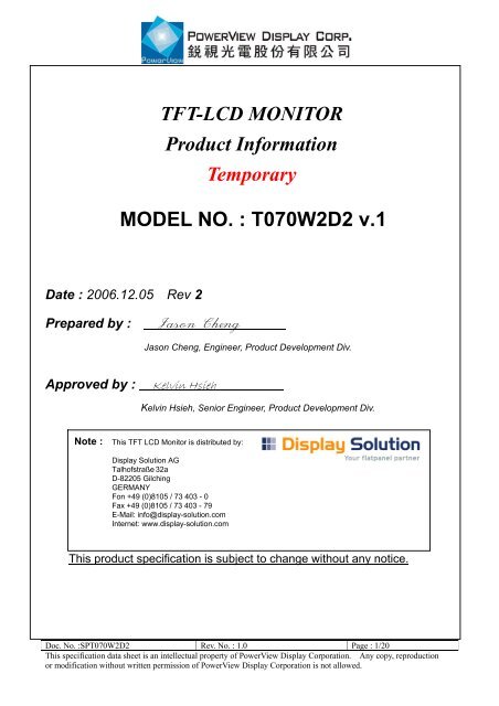
<strong>TFT</strong>-<strong>LCD</strong> <strong>MONITOR</strong><br />
Product Information<br />
Temporary<br />
MODEL NO. : T070W2D2 v.1<br />
Date : 2006.12.05 Rev 2<br />
Prepared by : Jason Cheng<br />
Approved by : Kelvin Hsieh<br />
Note :<br />
Jason Cheng, Engineer, Product Development Div.<br />
Kelvin Hsieh, Senior Engineer, Product Development Div.<br />
This product specification is subject to change without any notice.<br />
Doc. No. :SPT070W2D2 Rev. No. : 1.0 Page : 1/20<br />
This specification data sheet is an intellectual property of PowerView <strong>Display</strong> Corporation. Any copy, reproduction<br />
or modification without written permission of PowerView <strong>Display</strong> Corporation is not allowed.
Records of Revision<br />
Date Rev. No. Summary Page<br />
2006/11/26 01 First issue of T070W2D1 specification sheet<br />
2006/12/05 02 Change the outline dimension 5<br />
Change the control scheme of LED Driver 12<br />
Doc. No. :SPT070W2D2 Rev. No. : 1.0 Page : 2/20<br />
This specification data sheet is an intellectual property of PowerView <strong>Display</strong> Corporation. Any copy, reproduction<br />
or modification without written permission of PowerView <strong>Display</strong> Corporation is not allowed.
Contents Page<br />
1.0 Handling Precautions ------------------------- 4<br />
2.0 General Description ------------------------- 5<br />
2.1 General Application ------------- 5<br />
2.2 Main Features ------------- 5<br />
2.3 General Information ------------- 5<br />
2.3.1 <strong>Display</strong> Characteristics ------------- 5<br />
2.3.2 Mechanical Dimensions ------------- 6<br />
3.0 Absolute Maximum Ratings ------------------------- 6<br />
3.1 Absolute Ratings of Environment Requirement ------------- 6<br />
3.2 Electrical Absolute Ratings ------------- 6<br />
3.2.1 <strong>TFT</strong>-<strong>LCD</strong> Module ------------- 6<br />
3.2.2 DC-AC Module ------------- 6<br />
4.0 Optical Characteristics ------------------------- 7<br />
5.0 Electrical Characteristics ------------------------- 9<br />
5.1 AC Timing Characteristics -------------- 9<br />
5.2 DC Characteristics ------------- 9<br />
5.2.1 <strong>TFT</strong>-<strong>LCD</strong> Module -------------- 9<br />
5.2.2 DC-AC Module and Backlight Unit -------------- 10<br />
5.3 Input Terminal Pin Assignment -------------- 11<br />
5.3.1 Signal Input Interface -------------- 11<br />
5.3.2 DC-AC Power Input Interface -------------- 12<br />
5.3.3 Color Data Reference -------------- 12<br />
5.4 Input Timing Chart -------------- 14<br />
6.0 Pixel Format Image ----------------------- 15<br />
7.0 <strong>Display</strong> Outline Dimensions ---------------------- 15<br />
8.0 Labeling, Packaging & Others ---------------------- 17<br />
9.0 General Notices ----------------------- 19<br />
9.1 Reliability Test Item ------------- 19<br />
9.2 Storage, Operation & Others ------------- 20<br />
Doc. No. :SPT070W2D2 Rev. No. : 1.0 Page : 3/20<br />
This specification data sheet is an intellectual property of PowerView <strong>Display</strong> Corporation. Any copy, reproduction<br />
or modification without written permission of PowerView <strong>Display</strong> Corporation is not allowed.
1.0 Handling Precaution<br />
1.) Handle with care. Pay attention not to press or scratch the surface of the monitor,<br />
especially the polarizer. Do not twist or bend the monitor. It may cause un-recoverable<br />
damage.<br />
2.) Do not drop or bump the monitor since this monitor contains fragile glass components.<br />
Breakage of this monitor might cause leakage of the liquid crystal sealed inside the<br />
glasses. Do not touch the liquid crystal liquid in case of leakage. Flush with massive<br />
water immediately in case of contact with your skin by liquid crystal fluid and call<br />
for doctor for immediate medical treatment.<br />
3.) Be sure to turn off power supply while plug or un-plug the power input connector.<br />
4.) Clean up the polarizer only with soft solvent if necessary. The desirable cleaners are<br />
water, IPA(Isopropyl Alcohol) or Hexane. Do not use Ketone type materials (ex.<br />
Acetone), Ethyl alcohol, toluene, Ethyl acid or Methyl chloride. It will permanently<br />
damage the polarizer due to chemical reaction. 5.) Wipe off fluid drop immediately to<br />
prevent from possible discoloration or spots on the polarizer.<br />
6.) Do not twist nor bend the monitor structure, even momentarily. Bending or twisting<br />
torque may likely damage the internal components of the monitor.<br />
7.) The cold cathode fluorescent lamp in <strong>LCD</strong> contains small amount of mercury (Hg).<br />
Please refer to the design specification for application and the local regulations and<br />
environmental laws for disposal purpose.<br />
8.) Protect the monitor from static environment to prevent from damage to the CMOS gate<br />
array IC.<br />
Doc. No. :SPT070W2D2 Rev. No. : 1.0 Page : 4/20<br />
This specification data sheet is an intellectual property of PowerView <strong>Display</strong> Corporation. Any copy, reproduction<br />
or modification without written permission of PowerView <strong>Display</strong> Corporation is not allowed.
2.0 General Description<br />
T070W2D2 v.1 is a 7 inch (15:9 aspect ratio) color active matrix <strong>TFT</strong> <strong>LCD</strong> monitor with slim<br />
outlook and excellent display performance driven by a pure DIGITAL TTL interface. This<br />
monitor supports 800(H) x RGB x 480(V), stripe color pixel format, and 262,144 colors (RGB<br />
6 bits data) with outstanding color image and ALL-IN-ONE functionality, including a built-in<br />
DC-AC backlight inverter and DC-DC circuitry. Its outstanding performances with wide<br />
operation temperature range, -30 ~ 85ºC, ultra high brightness, 800 nits(typ.) and wide<br />
viewing angle(120 。 /100 。 ) make this monitor very suitable for applications under server<br />
environments or outdoor use. It provides customers with high design flexibilities, especially<br />
for industrial and medical applications.<br />
2.1 General Applications<br />
- <strong>Display</strong> terminal for applications of Car Navigation, Car PC, Industrial, Medical, Gaming,<br />
Amusement or more<br />
2.2 Main Features<br />
- Ultra High Brightness, Sunlight Readable<br />
- LED backlight<br />
- 15:9 <strong>Display</strong> Aspect Ratio<br />
- Wide Viewing Angle<br />
- Wide Operation Temperature Range<br />
- High Contrast Ratio<br />
- Pure Digital CMOS<br />
- Built-in DC-DC Circuit & LED Driver<br />
2.3 General Information<br />
2.3.1 <strong>Display</strong> Characteristics<br />
Item Specification Unit Note<br />
<strong>Display</strong> Area (HxV) 152.4 (H) x 91.44 (V) mm 7” Diagonal<br />
Driver Element a-Si <strong>TFT</strong> Active Matrix - -<br />
Number of Pixels (HxV) 800 x RGB x 480 pixel Wide 15:9<br />
Pixel Arrangement R.G.B Vertical Stripe - -<br />
Pixel Pitch (HxV) 0.1905 x 0.1905 mm Pixel<br />
<strong>Display</strong> Mode Normally White - -<br />
Viewing Angle (H/V) 140/120 degree 6 o’clock<br />
Signal Interface Digital RGB 18 bits 262K colors<br />
Doc. No. :SPT070W2D2 Rev. No. : 1.0 Page : 5/20<br />
This specification data sheet is an intellectual property of PowerView <strong>Display</strong> Corporation. Any copy, reproduction<br />
or modification without written permission of PowerView <strong>Display</strong> Corporation is not allowed.
2.3.2 Mechanical Dimensions<br />
Item Min. Typ. Max. Unit Note<br />
Horizontal 168.0 ±0.3 mm<br />
Dimension Vertical 111.8 mm ±0.3 mm<br />
Depth 14.2<br />
±0.3 mm<br />
Weight 304 g ±10 g<br />
3.0 Absolute Maximum Ratings<br />
3.1 Absolute Ratings of Environment Requirement<br />
Item Symbol Min. Max. Unit Note<br />
Storage Temperature Tstg -40 95 ºC<br />
Operation Temperature<br />
(Ambient Temperature)<br />
Topr -30 85 ºC<br />
3.2 Electrical Absolute Ratings<br />
3.2.1 <strong>TFT</strong>-<strong>LCD</strong> Module (Ta=25±2ºC), Vgg=GND=0V)<br />
Item SYMBOL Min. Max. UNIT NOTE<br />
Power Supply Voltage VDD -0.3 4.0 V (1),(2)<br />
Input Voltage Vi1 -0.3 5.3 V (1),(2),(3)<br />
3.2.2 LED Driver Module<br />
Item SYMBOL MIN MAX UNIT NOTE<br />
Power Supply Voltage VBL -0.3 15 V (1),(2)<br />
Input Voltage Vi2 -0.3 5.5 V (1),(2),(4)<br />
Note (1) Within operating temperature<br />
Note (2) Permanent damage to the device may occur if maximum values are exceeded.<br />
Functional operation should be restricted to the conditions described under normal<br />
operating conditions.<br />
Note (3) For all pins except power and ground pins<br />
Note (4) For pins “DIM” and “EN”<br />
Doc. No. :SPT070W2D2 Rev. No. : 1.0 Page : 6/20<br />
This specification data sheet is an intellectual property of PowerView <strong>Display</strong> Corporation. Any copy, reproduction<br />
or modification without written permission of PowerView <strong>Display</strong> Corporation is not allowed.
4.0 Optical Characteristics<br />
The following items are measured under stable conditions in a dark room or equivalent state.<br />
* Measuring Equipment: BM-5A, PR-650<br />
(VDD=3.3V, fV=60Hz, fH=15.734KHz, Ta=25±2ºC)<br />
Item Symbol Condition<br />
At<br />
Min. Typ. Max. Unit Note<br />
Contrast Ratio CR<br />
optimized<br />
Viewing<br />
Angle<br />
400 500 - (4)<br />
Response Rising TR - 10 20<br />
Time at<br />
θ=0º<br />
ms<br />
25ºC<br />
Falling TF<br />
VDim<br />
- 15 30<br />
Luminance YL =Vmax,<br />
25ºC<br />
- 800 cd/m 2<br />
(3)<br />
Color<br />
Chromaticity White<br />
WX θ =0º TBD<br />
(6)<br />
(CIE 1931)<br />
WY θ =0º TBD<br />
Viewing<br />
Angle<br />
Hor.<br />
Ver.<br />
θL<br />
θR<br />
θH<br />
CR≥10 at<br />
center<br />
point<br />
70<br />
70<br />
50<br />
70<br />
-<br />
-<br />
-<br />
-<br />
Degree (5)<br />
θL<br />
Note (1) : Ambient temperature =25℃, and Vdim = Vmax. To be measured in the dark room.<br />
Note (2) : To be measured on the center area of panel with a viewing cone of 1°by Topcon<br />
luminance meter BM-5, after 10 minutes operation.<br />
Note (3) : Definition of response time:<br />
The output signals of photo detector are measured when the input signals are<br />
changed from “black” to “white”(falling time) and from “white” to “black”(rising time),<br />
respectively.<br />
The response time is defined as the time interval between the 10% and 90% of<br />
amplitudes. Refer to figure as below.<br />
Doc. No. :SPT070W2D2 Rev. No. : 1.0 Page : 7/20<br />
This specification data sheet is an intellectual property of PowerView <strong>Display</strong> Corporation. Any copy, reproduction<br />
or modification without written permission of PowerView <strong>Display</strong> Corporation is not allowed.
Note (4) : Definition of contrast ratio:<br />
Contrast ratio is calculated with the following formula.<br />
Note (5) : Definition of viewing angle, Refer to figure as below.<br />
Note (6) : Measured at the center area of the panel when all the input terminals of <strong>LCD</strong> panel<br />
are electrically opened.<br />
Doc. No. :SPT070W2D2 Rev. No. : 1.0 Page : 8/20<br />
This specification data sheet is an intellectual property of PowerView <strong>Display</strong> Corporation. Any copy, reproduction<br />
or modification without written permission of PowerView <strong>Display</strong> Corporation is not allowed.
5.0 Electrical Characteristics<br />
5.1 AC Timing Characteristics<br />
Item Symbol Min. Typ. Max. Unit Note<br />
Clock Frequency Fck 31.95 33.26 34.60 MHz<br />
Clock Duty Ratio Tch/(Tch+Tcl) 40 50 60 %<br />
Hsync Period<br />
Th 1024 1056 1088 clk<br />
τh 31.45 31.75 32.05 µs τh=FckxTh<br />
Hsync Pulse Width Thw 5 128 186 clk<br />
Vsync Period Tv 520 525 530 Th<br />
Vsync Pulse Width Tvw 2 - Tv-515 Th<br />
Hsync/Vsync Phase<br />
Shift<br />
Tvpd 2 - - clk<br />
Horizontal <strong>Display</strong><br />
Period<br />
Thd 800 clk<br />
Vertical <strong>Display</strong><br />
Period<br />
Tvd 480 Th<br />
Hsync Clock Shift Thc 10 - (Tch+Tcl)-10 ns<br />
Data Setup Time Tds 5 - - ns<br />
Data Hold Time Tch 10 - - ns<br />
5.2 DC Characteristics<br />
5.2.1 <strong>TFT</strong>-<strong>LCD</strong> Module<br />
Item Symbol Min. Typ. Max. Unit Note<br />
Supply Voltage<br />
VDD<br />
IDD<br />
3.0<br />
-<br />
3.30<br />
130<br />
3.6 V<br />
mA<br />
(1)<br />
(2)<br />
Permissive Input<br />
Ripple Voltage<br />
VRF - - 100 mVP-P VDD=3.3V<br />
Input Logic High VIH 0.7 VDD VDD V<br />
Input Logic Low VIL 0 0.3 VDD V<br />
Doc. No. :SPT070W2D2 Rev. No. : 1.0 Page : 9/20<br />
This specification data sheet is an intellectual property of PowerView <strong>Display</strong> Corporation. Any copy, reproduction<br />
or modification without written permission of PowerView <strong>Display</strong> Corporation is not allowed.
Note (1) VDD Power-On condition :<br />
0.9 VDD<br />
0.1 VDD<br />
t1 t2<br />
VDD<br />
t3<br />
0.9 VDD<br />
Note (2) Conditions for current consumption :<br />
0 < t1 ≤ 20 ms<br />
0 < t2 ≤ 50 ms<br />
t3 ≤ 1 s<br />
8 Gray Scale Pattern, VDD=3.3V, fH=31.5KHz, fV=60.0Hz, fCLK=33.26MHz<br />
5.2.2 Backlight Unit and LED Driver<br />
Item Symbol Min. Typ. Max. Unit Note<br />
Power Supply<br />
VBL 10.8 12 13.2 V<br />
IBL 0.48 Amp VBL = 12V<br />
Dimming Voltage VDim 1.0 1.5 V<br />
Enable Voltage VEN 0.5 V<br />
5.3 Input Terminal Pin Assignment<br />
5.3 Input Terminal Pin Assignment<br />
5.3.1 Signal Input Interface<br />
Kyocera Elco Connector : 40 FFC/FPC Type : 08-6210-033-340-800<br />
Pin No Symbol Description Remark<br />
1 GND Ground -<br />
2 GND Ground -<br />
3 NC No Connection -<br />
4 VDD Power Supply for Logic (+3.3V) -<br />
5 VDD Power Supply for Logic (+3.3V) -<br />
6 VDD Power Supply for Logic (+3.3V) -<br />
7 VDD Power Supply for Logic (+3.3V) -<br />
8 NC No Connection -<br />
9 DE Data Enable -<br />
10 GND Ground -<br />
Doc. No. :SPT070W2D2 Rev. No. : 1.0 Page : 10/20<br />
This specification data sheet is an intellectual property of PowerView <strong>Display</strong> Corporation. Any copy, reproduction<br />
or modification without written permission of PowerView <strong>Display</strong> Corporation is not allowed.
11 GND Ground -<br />
12 GND Ground -<br />
13 B5 Blue Data (MSB) -<br />
14 B4 Blue Data -<br />
15 B3 Blue Data -<br />
16 GND Ground -<br />
17 B2 Blue Data -<br />
18 B1 Blue Data -<br />
19 B0 Blue Data (LSB) -<br />
20 GND Ground -<br />
21 G5 Green Data (MSB) -<br />
22 G4 Green Data -<br />
23 G3 Green Data -<br />
24 GND Ground -<br />
25 G2 Green Data -<br />
26 G1 Green Data -<br />
27 G0 Green Data (LSB) -<br />
28 GND Ground -<br />
29 R5 Red Data (MSB) -<br />
30 R4 Red Data -<br />
31 R3 Red Data<br />
32 GND Ground<br />
33 R2 Red Data<br />
34 R1 Red Data<br />
35 R0 Red Data (LSB)<br />
36 GND Ground<br />
37 GND Ground<br />
38 GND Ground<br />
39 CLK Data Clock<br />
40 GND Ground<br />
Doc. No. :SPT070W2D2 Rev. No. : 1.0 Page : 11/20<br />
This specification data sheet is an intellectual property of PowerView <strong>Display</strong> Corporation. Any copy, reproduction<br />
or modification without written permission of PowerView <strong>Display</strong> Corporation is not allowed.
5.3.2 LED Driver Unit<br />
Connector : ACES 88290-0601 pitch 2.0mm 6 pins CN<br />
Mode 1 : Matching Connector : ACES 86809-0600 CN<br />
Pin No. Symbol Description Remark<br />
1 VBL Power Supply for LED Driver<br />
2 VBL Power Supply for LED Driver<br />
3 EN/DIM LED Enable & Dimming Control Input Note 1<br />
4 NC No Connection<br />
5 GND Ground Pin for LED Driver<br />
6 GND Ground Pin for LED Driver<br />
Note 1 : The “Enable & Dimming Control” of the LED driver shares the same pinning.<br />
The LED backlight will turn on when the input voltage of this pin exceeds +0.6V.<br />
The LED current/brightness will be adjustable by applying an analog voltage between<br />
+0.8 ~ +1.3V(Max. Brightness).<br />
Mode 2:<br />
Pin No. Symbol Description Remark<br />
1 VBL Power Supply for LED Driver<br />
2 VBL Power Supply for LED Driver<br />
3 EN LED Enable Control Input Note 1<br />
4 DIM Dimming Control Input Note 2<br />
5 GND Ground Pin for LED Driver<br />
6 GND Ground Pin for LED Driver<br />
Note 1 : Disable VEN1.6 V<br />
Note 2 : Max Brightness VDIM : 0V, Min Brightness VDIM : 2V ( ≈ 0 Nit )<br />
5.3.3 Color Data Reference<br />
The below table is about nput signal, Basic display colors and gray scale of each color.<br />
0 : Low Level Voltage 1 : High Level Voltage<br />
Each basic color can be displayed in 64 gray scales from 6 bit data signals. With the<br />
combination of total 18 bit data signals, the 262,144 color display can be achieved on the<br />
screen.<br />
- Please refer to the next page<br />
Doc. No. :SPT070W2D2 Rev. No. : 1.0 Page : 12/20<br />
This specification data sheet is an intellectual property of PowerView <strong>Display</strong> Corporation. Any copy, reproduction<br />
or modification without written permission of PowerView <strong>Display</strong> Corporation is not allowed.
Basic Color<br />
Gray Scale of Red<br />
Gray Scale of Green<br />
Gray Scale of Blue<br />
Colors<br />
& Gray<br />
Scale<br />
Gray<br />
Scale<br />
Data Signal<br />
R0 R1 R2 R3 R4 R5 G0 G1 G2 G3 G4 G5 B0 B1 B2 B3 B4 B5<br />
Black - 0 0 0 0 0 0 0 0 0 0 0 0 0 0 0 0 0 0<br />
Blue - 0 0 0 0 0 0 0 0 0 0 0 0 1 1 1 1 1 1<br />
Green - 0 0 0 0 0 0 1 1 1 1 1 1 0 0 0 0 0 0<br />
Cyan - 0 0 0 0 0 0 1 1 1 1 1 1 1 1 1 1 1 1<br />
Red - 1 1 1 1 1 1 0 0 0 0 0 0 0 0 0 0 0 0<br />
Magenta - 1 1 1 1 1 1 0 0 0 0 0 0 1 1 1 1 1 1<br />
Yellow - 1 1 1 1 1 1 1 1 1 1 1 1 0 0 0 0 0 0<br />
White - 1 1 1 1 1 1 1 1 1 1 1 1 1 1 1 1 1 1<br />
Black GS0 0 0 0 0 0 0 0 0 0 0 0 0 0 0 0 0 0 0<br />
� GS1 1 0 0 0 0 0 0 0 0 0 0 0 0 0 0 0 0 0<br />
Darker GS2 0 1 0 0 0 0 0 0 0 0 0 0 0 0 0 0 0 0<br />
� � � � �<br />
� � � �<br />
Brighter GS61 1 0 1 1 1 1 0 0 0 0 0 0 0 0 0 0 0 0<br />
� GS62 0 1 1 1 1 1 0 0 0 0 0 0 0 0 0 0 0 0<br />
Red GS63 1 1 1 1 1 1 0 0 0 0 0 0 0 0 0 0 0 0<br />
Black GS0 0 0 0 0 0 0 0 0 0 0 0 0 0 0 0 0 0 0<br />
� GS1 0 0 0 0 0 0 1 0 0 0 0 0 0 0 0 0 0 0<br />
Darker GS2 0 0 0 0 0 0 0 1 0 0 0 0 0 0 0 0 0 0<br />
� � �<br />
� � �<br />
Brighter GS61 0 0 0 0 0 0 1 0 1 1 1 1 0 0 0 0 0 0<br />
� GS62 0 0 0 0 0 0 0 1 1 1 1 1 0 0 0 0 0 0<br />
Green GS63 0 0 0 0 0 0 1 1 1 1 1 1 0 0 0 0 0 0<br />
Black GS0 0 0 0 0 0 0 0 0 0 0 0 0 0 0 0 0 0 0<br />
� GS1 0 0 0 0 0 0 0 0 0 0 0 0 1 0 0 0 0 0<br />
Darker GS2 0 0 0 0 0 0 0 0 0 0 0 0 0 1 0 0 0 0<br />
� �<br />
� �<br />
Brighter GS61 0 0 0 0 0 0 0 0 0 0 0 0 1 0 1 1 1 1<br />
� GS62 0 0 0 0 0 0 0 0 0 0 0 0 0 1 1 1 1 1<br />
Blue GS63 0 0 0 0 0 0 0 0 0 0 0 0 1 1 1 1 1 1<br />
Doc. No. :SPT070W2D2 Rev. No. : 1.0 Page : 13/20<br />
This specification data sheet is an intellectual property of PowerView <strong>Display</strong> Corporation. Any copy, reproduction<br />
or modification without written permission of PowerView <strong>Display</strong> Corporation is not allowed.<br />
P
5.4 Input Timing Chart<br />
Tv<br />
Vs<br />
Th<br />
Tvw<br />
Hs<br />
Tve Tvf<br />
X,233 X,234 Invalid X,1 X,2 X,3 X,233 X,234<br />
Invalid<br />
RGB<br />
Tvd<br />
Thw<br />
DE<br />
Hs<br />
Th<br />
Doc. No. :SPT070W2D2 Rev. No. : 1.0 Page : 14/20<br />
This specification data sheet is an intellectual property of PowerView <strong>Display</strong> Corporation. Any copy, reproduction<br />
or modification without written permission of PowerView <strong>Display</strong> Corporation is not allowed.<br />
CLK<br />
The<br />
RGB<br />
320,Y invalid<br />
1,Y 2,Y 3,Y 319,Y 480,Y invalid<br />
Thd<br />
Vs<br />
VIH<br />
VIL<br />
RGB,<br />
VIL<br />
Hs<br />
VIH<br />
VIL<br />
CLK<br />
VIH<br />
Tds<br />
Tcl<br />
Tch<br />
Tvpd<br />
Tdh<br />
Hs<br />
VIL<br />
CLK<br />
VIL<br />
Thc
6.0 Pixel Format Image<br />
7.0 <strong>Display</strong> Outline Dimensions<br />
7.1 Monitor Outline Dimensions<br />
- Please refer to the next page<br />
Doc. No. :SPT070W2D2 Rev. No. : 1.0 Page : 15/20<br />
This specification data sheet is an intellectual property of PowerView <strong>Display</strong> Corporation. Any copy, reproduction<br />
or modification without written permission of PowerView <strong>Display</strong> Corporation is not allowed.
Doc. No. :SPT070W2D2 Rev. No. : 1.0 Page : 16/20<br />
This specification data sheet is an intellectual property of PowerView <strong>Display</strong> Corporation. Any copy, reproduction<br />
or modification without written permission of PowerView <strong>Display</strong> Corporation is not allowed.
8.0 Labeling, Packaging & Others<br />
* Labeling<br />
10 mm<br />
* Packaging<br />
T070W2D2<br />
Z1 Z2 Z3 Z4Z5Z6Z7Z8<br />
- Please refer to the next page<br />
35 mm<br />
<strong>POWERVIEW</strong> <strong>DISPLAY</strong><br />
MADE IN TAIWAN<br />
Doc. No. :SPT070W2D2 Rev. No. : 1.0 Page : 17/20<br />
This specification data sheet is an intellectual property of PowerView <strong>Display</strong> Corporation. Any copy, reproduction<br />
or modification without written permission of PowerView <strong>Display</strong> Corporation is not allowed.<br />
v.1<br />
Production Sequence No.<br />
Product Category<br />
Manufacturing Date<br />
Manufacturing Month<br />
Manufacturing Year, last digit<br />
Assembly Plant<br />
Marking<br />
Product Version
Doc. No. :SPT070W2D2 Rev. No. : 1.0 Page : 18/20<br />
This specification data sheet is an intellectual property of PowerView <strong>Display</strong> Corporation. Any copy, reproduction<br />
or modification without written permission of PowerView <strong>Display</strong> Corporation is not allowed.<br />
+
9.0 General Notice<br />
9.1 Reliability Test Items (Note 2)<br />
Note1: Ta: Ambient temperature.<br />
Note 2: In the standard conditions, there is not display function NG issue occurred. All the<br />
cosmetic specification is judged before the reliability stress.<br />
Doc. No. :SPT070W2D2 Rev. No. : 1.0 Page : 19/20<br />
This specification data sheet is an intellectual property of PowerView <strong>Display</strong> Corporation. Any copy, reproduction<br />
or modification without written permission of PowerView <strong>Display</strong> Corporation is not allowed.
9.2 Storage, Operation & Others<br />
(a) Do not leave the panel in high temperature, and high humidity for a long time.<br />
It is highly recommended to store the module with temperature from 0 to 35°C and<br />
relative humidity of less than 70%.<br />
(b) Do not store the <strong>TFT</strong>-<strong>LCD</strong> module in direct sunlight.<br />
(c) The module shall be stored in a dark place. It is prohibited to apply sunlight or<br />
fluorescent light during the store.<br />
(d) Do not connect, disconnect the module in the "Power On" condition.<br />
(e) Power supply should always be turned on/off by the item 3.2 "Electrical Absolute<br />
Ratings"<br />
(f) The liquid-crystal is deteriorated by ultraviolet rays. Do not leave it in direct sunlight<br />
and strong ultraviolet rays for many hours.<br />
(g) Avoid condensation of water. It may result in improper operation or disconnection of<br />
electrode.<br />
(h) Do not exceed the absolute maximum rating value. (the supply voltage variation, input<br />
voltage variation, variation in part contents and environmental temperature, and so on)<br />
Otherwise the panel may be damaged.<br />
(i) If the panel displays the same pattern continuously for a long period of time, it can be<br />
the situation when the image "Sticks" to the screen.<br />
(j) This panel has its circuitry FPC on the bottom side and should be handled carefully in<br />
order not to be stressed.<br />
Doc. No. :SPT070W2D2 Rev. No. : 1.0 Page : 20/20<br />
This specification data sheet is an intellectual property of PowerView <strong>Display</strong> Corporation. Any copy, reproduction<br />
or modification without written permission of PowerView <strong>Display</strong> Corporation is not allowed.