Ultra Fine-Grained Metals Prepared by Severe Plastic Deformation ...
Ultra Fine-Grained Metals Prepared by Severe Plastic Deformation ...
Ultra Fine-Grained Metals Prepared by Severe Plastic Deformation ...

Create successful ePaper yourself
Turn your PDF publications into a flip-book with our unique Google optimized e-Paper software.
Vol. 107 (2005) ACTA PHYSICA POLONICA A No. 5<br />
Proceedings of the 35th Polish Seminar on Positron Annihilation, Turawa, Poland 2004<br />
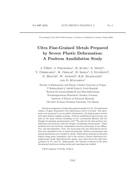
<strong>Ultra</strong> <strong>Fine</strong>-<strong>Grained</strong> <strong>Metals</strong> <strong>Prepared</strong><br />
<strong>by</strong> <strong>Severe</strong> <strong>Plastic</strong> <strong>Deformation</strong>:<br />
A Positron Annihilation Study<br />
J. Číˇzeka , I. Procházka a , R. Kuˇzel a , Z. Matěj a ,<br />
V. Cherkaska a , M. Cieslar a , B. Smola a , I. Stulíková a ,<br />
G. Brauer b , W. Anwand b , R.K. Islamgaliev c<br />
and O. Kulyasova c<br />
a Faculty of Mathematics and Physics, Charles University in Prague<br />
V Holeˇsovičkách 2, 180 00 Praha 8, Czech Republic<br />
b Institut für Ionenstrahlphysik und Materialforschung<br />
Forschungszentrum Rossendorf, Dresden, Germany<br />
c Institute of Physics of Advanced Materials<br />
Ufa State Aviation Technical University, Ufa, Russia<br />
Recent investigations of ultra fine-grained metals (Cu, Fe, Ni) performed<br />
within a Prague–Rossendorf–Ufa collaboration will be reviewed. The specimens<br />
were prepared <strong>by</strong> severe plastic deformation: the high-pressure torsion<br />
and equal channel angular pressing. Positron annihilation spectroscopy was<br />
used as the main method including (i) the conventional lifetime and the<br />
Doppler broadening measurements with 22 Na and (ii) the slow-positron implantation<br />
spectroscopy with the Doppler broadening measurement. Other<br />
methods were also involved: transmission electron microscopy, X-ray diffraction,<br />
and microhardness. First, the mean grain size was determined and defects<br />
were identified in the as-deformed materials. Defects concentration and<br />
spatial distribution were studied in detail. Dislocations situated in distorted<br />
regions along grain boundaries, and a few-vacancy clusters distributed homogeneously<br />
inside dislocations-free grains, were observed in the ultra fine-<br />
-grained Cu, Fe, and Ni. Subsequently, the thermal evolution of the ultra<br />
fine-grained structures during isochronal annealing was studied.<br />
PACS numbers: 78.70.Bj, 79.60.Jv<br />
(745)
746 J. Číˇzek et al.<br />
1. Introduction<br />
Over the past several decades it has become known that the refinement of<br />
grain size of the traditional polycrystalline metals below one micrometer can lead<br />
to a significant improvement of their mechanical, electrical, thermal, and other<br />
properties. This is why ultra fine-grained (UFG) metals, which are characterised<br />
with a mean grain size of several hundreds of nanometers, are nowadays attracting<br />
much attention of materials researchers as promising materials for various<br />
industrial applications. Among the methods of production of the UFG metals,<br />
those based on severe plastic deformation (SPD) are of a great importance, see<br />
Refs. [1, 2] for a review. Macroscopic amounts of UFG materials with no porosity<br />
can be obtained <strong>by</strong> means of SPD. The following important elements of the<br />
SPD-created UFG structures can be outlined:<br />
(i) Grains of the size of several hundreds of nanometers, which becomes comparable<br />
to typical diffusion lengths of free positrons in metals (≈ 100 nm).<br />
(ii) Grain boundaries (GB) whose integrated volume constitutes, contrary to the<br />
ordinary polycrystalline metals, a significant fraction of the total volume of<br />
the material.<br />
(iii) Defects introduced <strong>by</strong> SPD (dislocations, vacancies and vacancy clusters,<br />
GBs).<br />
The two techniques utilising SPD have recently been introduced to produce<br />
UFG structures in a wide class of metallic systems [2]:<br />
(a) The high-pressure torsion (HPT) is a technique capable to provide disk-<br />
-shaped specimens of the diameter of ≈ 10 mm and thickness of 0.2÷0.5 mm.<br />
The HPT-made specimens exhibit rather small grain size of ≈ 100 nm, homogeneous<br />
UFG structure, and a weak texture only.<br />
(b) The equal channel angular pressing (ECAP) can produce more massive specimens,<br />
however, the mean grain size usually appears to be larger compared<br />
to HPT.<br />
SPD process results in a highly non-equilibrium structure. It seems obvious<br />
that defects play a key role in formation of the UFG structure and lie beneath<br />
the extraordinary properties of these materials. Detailed defect investigations<br />
become thus highly desirable from the point of understanding the formation and<br />
thermal stability of the UFG structures. Positron annihilation spectroscopy (PAS)<br />
is a powerful non-destructive technique of microstructural studies of a variety<br />
materials [3]. It appears to be extremely sensitive to the small-sized open-volume<br />
defects. PAS thus seems to be an ideal tool for the investigation of the above listed<br />
UFG structure elements.<br />
In the present lecture, recent investigations of the HPT-prepared UFG metals,<br />
performed within a Prague–Rossendorf–Ufa collaboration, will be reviewed.<br />
PAS was utilised as the principal experimental technique including:
<strong>Ultra</strong> <strong>Fine</strong>-<strong>Grained</strong> <strong>Metals</strong> <strong>Prepared</strong> . . . 747<br />
(i) the conventional lifetime and the Doppler broadening (DB) measurements<br />
with 22 Na positron source and<br />
(ii) the slow-positron implantation spectroscopy (SPIS) with DB measurements.<br />
Other experimental methods, complementary to PAS, were also involved in<br />
these investigations: the transmission electron microscopy (TEM), X-ray diffraction<br />
(XRD), and microhardness measurements. The present lecture will concentrate<br />
on the results obtained for the Cu, Fe, Ni UFG metals and Cu+Al2O3 composite.<br />
The Mg-based UFG metallic systems have been studied within the above<br />
collaboration, too. These results are presented elsewhere at this Conference [4].<br />
2. Experiments<br />
2.1. Specimens<br />
The UFG specimens dealt with here are listed in the first column of Table.<br />
The HPT-made specimens of the UFG Cu, Fe, Ni metals and Cu+Al2O3 composite<br />
were prepared at room temperature (RT) <strong>by</strong> a technique described in Ref. [2].<br />
Torsion was performed up to a true logarithmic strain of ε = 7 under a high<br />
pressure of 6 GPa. A set of the UFG Cu specimens deformed under a pressure<br />
of 3 GPa was prepared, too. All the HPT-made specimens were disk-shaped with<br />
a diameter of 10÷12 mm and thickness of 0.2÷0.4 mm. A set of the UFG Cu<br />
specimens prepared <strong>by</strong> the ECAP technique [2] (route Bc, i.e. the pressed sample<br />
is rotated <strong>by</strong> 90 ◦ after each pass, 12 passes, RT) was also involved in the present<br />
investigations.<br />
TABLE<br />
Positron lifetimes τi and relative intensities Ii (i = 1, 2) observed in as-deformed UFG<br />
samples. The errors (one standard deviation) are given in parentheses in units of the<br />
last significant digits. Symbol nV denotes number of vacancies constituting vacancy<br />
clusters (microvoids), see the text for details.<br />
Sample τ1 [ps] I1 [%] τ2 [ps] I2 [%] nV<br />
HPT deformed Cu, p = 6 GPa 161(3) 64(4) 249(5) 36(4) 4.8(3)<br />
HPT deformed Cu, p = 3 GPa 164(1) 83(4) 255(4) 17(3) 5.2(3)<br />
HPT deformed Cu+0.5 wt.% 161(3) 60.4(5) 257(1) 39.6(5) 5.31(7)<br />
Al2O3 (GlidCop), p = 6 GPa<br />
ECAP deformed Cu, 164(3) 80(6) 240(10) 20(6) 4.2(6)<br />
route Bc, 12 passes<br />
HPT deformed Ni, p = 6 GPa 157(1) 88.9(6) 336(8) 11.1(6) 13.1(6)<br />
HPT deformed Fe, p = 6 GPa 150.9(4) 90.6(3) 352(6) 9.5(3) 13.2(5)
748 J. Číˇzek et al.<br />
2.2. Apparatus<br />
Conventional PAS. A BaF2 lifetime spectrometer described in Ref. [5] was<br />
employed in the course of present work. The spectrometer exhibited a time resolution<br />
of 150÷170 ps (FWHM) for 22 Na and a coincidence count rate of ≈ 100<br />
coincidence events per second. A carrier-free 22 NaCl (Amersham) positron source<br />
of ≈ 1.5 MBq strength sealed between 2 µm mylar D foils (DuPont) was used.<br />
The diameter of radioactive spot was ≈ 3 mm. At least 10 7 counts were collected<br />
in each lifetime spectrum. The measured spectra were decomposed in up to five<br />
exponential components (including ≈ 7% contribution arising from annihilation<br />
in the source) using the maximum likelihood procedure [5]. The conventional DB<br />
measurements were performed with a HPGe detector (1.7 keV FWHM at 511 keV).<br />
SPIS. SPIS measurements were performed on the magnetically guided<br />
positron beam facility “SPONSOR” at FZ Rossendorf [6]. Line shapes of annihilation<br />
γ-rays were measured with a HPGe detector having an energy resolution<br />
(FWHM) of 1.09 keV at 511 keV. The beam diameter at the sample surface was<br />
≈ 4 mm. The dependences of annihilation line shape parameters S on positron<br />
energy E were measured in the interval E = 30 eV ÷ 35 keV and analysed <strong>by</strong><br />
means of the VEPFIT code [7].<br />
Other methods. TEM observations were performed using a JEOL 2000 FX<br />
electron microscope operating at 200 kV. XRD investigations were carried out on<br />
XRD7 and HZG4 (Seifert-FPM) powder diffractometers using Cu Kα radiation.<br />
The microhardness HV was measured <strong>by</strong> the Vickers method <strong>by</strong> means of a LECO<br />
M-400-A hardness tester with a load of 100 g applied for 10 s.<br />
3. Results and discussion<br />
In this section, the main results obtained on SPD-prepared UFG Cu, Ni, Fe<br />
and Cu + Al2O3 will be briefly presented while the details of these investigations<br />
have been given elsewhere [8–13].<br />
3.1. Characterisation of as-deformed UFG specimens<br />
All the UFG materials listed in Table exhibited two lifetime components.<br />
Corresponding lifetimes τi and intensities Ii (i = 1, 2) were shown in columns 2<br />
thru 5 of Table. As the measured lifetimes significantly exceed the respective bulk<br />
ones, both the observed components come from positrons trapped at defects. Thus<br />
saturated positron trapping takes place in the as-deformed specimens indicating<br />
high defect densities created <strong>by</strong> SPD.<br />
The dominating component with the shorter lifetime τ1 is slightly lower than<br />
the lifetimes of positrons trapped in monovacancies in respective materials which<br />
is typical of positron trapping at dislocations. For example, the lifetimes for monovacancies<br />
in Cu and Ni were observed [14] to be of 168–170 ps, i.e. <strong>by</strong> about 10 ps
<strong>Ultra</strong> <strong>Fine</strong>-<strong>Grained</strong> <strong>Metals</strong> <strong>Prepared</strong> . . . 749<br />
higher than present values of τ1. Indeed, TEM observations on UFG Cu, Ni and<br />
Fe performed within present investigations revealed a strongly non-uniform spatial<br />
distribution of dislocations: grain interiors almost free of dislocations separated<br />
<strong>by</strong> distorted regions along GBs with a high dislocation density. Hencefore, one<br />
concludes that τ1-component in the UFG materials of Table arises from positrons<br />
trapped at dislocations situated in the distorted regions along GBs. However, this<br />
cannot be regarded as a general conclusion because, as reported at this Conference<br />
[4], a uniform distribution of dislocations was found in the HPT-processed UFG<br />
Mg–10%Gd alloy. As it was discussed in Ref. [4], the uniform spatial distribution<br />
of dislocations seems to be present predominantly in HPT-deformed metals with<br />
the hcp structure as a consequence of a lower number of slip systems compared to<br />
the fcc and bcc metals.<br />
The longer lifetime τ2 represents a contribution of positrons trapped in vacancy<br />
clusters referred to as microvoids below. The formation of vacancy clusters<br />
in these materials is to be considered here since a large number of vacancies are<br />
created during SPD. Vacancies are mobile at RT in the metals under study [15] so<br />
that they can diffuse to sinks at GBs, decorate dislocations present in the sample<br />
and a portion of vacancies can form small vacancy clusters. The latter process<br />
obviously becomes more likely inside the dislocation-free grain interiors as it appeared<br />
to be suppressed in HPT-deformed Mg–10%Gd alloy with homogeneously<br />
distributed dislocations [4]. The average size of vacancy clusters, i.e. an average<br />
number of vacancies nV constituting the clusters, was estimated from the comparison<br />
of the measured lifetime τ2 with that calculated ab initio on the basis of<br />
the density functional theory. Details of such calculations for Cu, Ni, and Fe were<br />
given elsewhere [8, 10, 16] and the results were included in the last column of Table.<br />
The intra-comparison of the nV-values shown in Table suggests a conclusion that<br />
the size of microvoids depends primarily on the material under question (through<br />
the different mobility of vacancies in different metals) and its dependence on the<br />
deformation method is of less importance [12].<br />
3.2. Spatial distribution of defects<br />
Since a key role of defects in the formation and properties of UFG structures<br />
is obvious, spatial distribution of defects resulting from HPT deformation<br />
may serve as a valuable test of optimum parameters of the deformation process.<br />
Spatial distribution of defects was investigated on the UFG Cu specimen, produced<br />
<strong>by</strong> HPT at 6 GPa, <strong>by</strong> means of SPIS and conventional PAS supplemented<br />
<strong>by</strong> TEM, XRD, and microhardness measurements [11, 13]. In order to obtain<br />
depth dependence of defect density at a larger depth scale the specimen was subjected<br />
to a controlled chemical etching. The S-parameter values corresponding to<br />
positron annihilation in the bulk were found to decrease gradually up to an 18 µm<br />
layer removed <strong>by</strong> etching. Then, no further decrease in S-values in the bulk was<br />
observed. Since the decrease in S indicates a corresponding decrease in defect
750 J. Číˇzek et al.<br />
density, one can conclude that the concentration of defects decreases with depth<br />
in a surface layer of ≈ 18 µm thickness and at deeper layers remains unchanged.<br />
This decrease comes primarily from the decrease in concentration of microvoids<br />
with depth and also from a slight increase in grain size with depth suggested <strong>by</strong><br />
XRD investigations (see Ref. [11] for details).<br />
Radial dependence of defect concentrations was also inspected <strong>by</strong> PAS and<br />
SPIS. The following main results were obtained [11]:<br />
• There is no radial change in the mean grain size, a value of 120±20 nm being<br />
measured <strong>by</strong> TEM. This is in reasonable agreement with XRD findings. Also<br />
the dislocation density was found <strong>by</strong> XRD to remain unchanged with radial<br />
distance from the centre of disk.<br />
• On the other hand, it was found that size and density of microvoids vary<br />
with the radial distance from the centre of the sample.<br />
3.3. Thermal stability of UFG structure<br />
The investigation of the thermal stability of the UFG structures can contribute<br />
to understanding the physical processes in the UFG metals, but is also<br />
important from the point of view of the industrial application of these materials.<br />
Isochronal annealing curves were measured on HPT-made UFG Cu (two specimens<br />
prepared under 3 and 6 GPa pressure) and Cu+Al2O3. The difference in<br />
the pressure resulted in a difference in the mean grain size of the UFG Cu specimens,<br />
as measured <strong>by</strong> TEM: 150 and 105 nm, respectively. Annealing steps were<br />
30 ◦ C. Specimens were annealed for 30 min at each temperature. Each annealing<br />
step was finished <strong>by</strong> quenching to water of room temperature. In Fig. 1, the<br />
Fig. 1. The thermal evolution of volume fraction η of distorted regions along GBs<br />
with annealing temperature as obtained from the analysis of positron lifetime data<br />
within the diffusion trapping model [8]: UFG Cu (6 GPa) — open circles, UFG Cu<br />
(3 GPa) — filled circles and UFG Cu+0.5 wt.% Al2O3 composite — open triangles.
<strong>Ultra</strong> <strong>Fine</strong>-<strong>Grained</strong> <strong>Metals</strong> <strong>Prepared</strong> . . . 751<br />
temperature dependence of the volume fraction η of distorted regions along GBs,<br />
deduced for UFG Cu (3 GPa) and Cu+Al2O3 from PAS data using the diffusion<br />
trapping model [8], is compared with UFG Cu (6 GPa). We can outline here the<br />
main results of these annealing experiments (see Refs. [8, 10, 11] for details):<br />
• In both Cu specimens, the recovery of the UFG structure is realised <strong>by</strong> the<br />
same processes. The abnormal grain growth when isolated recrystallised<br />
grains appear in virtually unchanged deformed matrix is followed at higher<br />
temperatures <strong>by</strong> recrystallisation in the whole volume of the specimen.<br />
• The recrystallisation process was found to start around 300 ◦ C in HPT-<br />
-deformed Cu under 3 GPa (mean grain size of 150 nm). In the case of<br />
the HPT Cu, deformed under 6 GPa (finer grains of 105 nm size), the start<br />
of recrystallisation is moved to about 200 ◦ C, i.e. <strong>by</strong> about 100 ◦ C towards<br />
lower temperatures (see Fig. 1).<br />
• Activation energy of recrystallisation in the UFG Cu, deduced from the<br />
present annealing experiments, corresponds reasonably well with the activation<br />
energy of migration of the equilibrium grains in the coarse-grained<br />
Cu.<br />
• The same sequence of recrystallisation processes as in the UFG Cu appears<br />
also in UFG Cu+Al2O3 composite, however, the temperature region of recrystallisation<br />
is shifted <strong>by</strong> almost 300 ◦ C towards higher temperatures in the<br />
composite with respect to UFG Cu (6 GPa), see Fig. 1.<br />
4. Summary<br />
UFG structures in Cu, Fe, Ni metals, and Cu+0.5wt.%Al2O3 composite processed<br />
<strong>by</strong> SPD were studied in detail <strong>by</strong> means of PAS techniques in combination<br />
with TEM, XRD, and microhardness measurement. Defects were identified and<br />
their concentrations and spatial distributions were investigated. Dislocations situated<br />
in distorted regions along GBs and small vacancy clusters distributed homogeneously<br />
inside dislocation-free grain interiors were observed. In the HPT-made<br />
Cu, the size and density of vacancy clusters were found to vary with depth and<br />
radial distance from the sample centre. Thermal stability of the UFG structure<br />
was shown to be influenced <strong>by</strong> the average grain size in the as-deformed material.<br />
The Al2O3 nanoparticles were shown to improve thermal stability of the HPT<br />
made Cu.<br />
Acknowledgments<br />
This work was partially supported <strong>by</strong> the Czech Ministry of Education,<br />
Youths, and Sports under contracts COST OC523.50, 1K03025 and KONTAKT
752 J. Číˇzek et al.<br />
ME0556. Support from The Grant Agency of Czech Republic (project GA<br />
106/01/D049) is also acknowledged.<br />
References<br />
[1] Nanomaterials <strong>by</strong> <strong>Severe</strong> <strong>Plastic</strong> <strong>Deformation</strong>, Proc. Conf. “Nanomaterials <strong>by</strong><br />
<strong>Severe</strong> <strong>Plastic</strong> <strong>Deformation</strong> — NANOSPD2”, Vienna 2002, Eds. M. Zehetbauer,<br />
R.Z. Valiev, Wiley-VCH Verlag GmbH&Co. KgaA, Weinheim 2004.<br />
[2] R.Z. Valiev, R.K. Islamgaliev, I.V. Aleksandrov, Prog. Mater. Sci. 45, 103 (2000).<br />
[3] P. Hautojärvi, C. Corbel, in: Positron Spectroscopy of Solids, Proc. Int. School<br />
of Physics “Enrico Fermi”, Course CXXV, Eds. A. Dupasquier, A.P. Mills, Jr.,<br />
Varenna (Italy) 1993, IOS Press, Amsterdam 1995, p. 491.<br />
[4] J. Číˇzek, I. Procházka, B. Smola, I. Stulíková, R. Kuˇzel, Z. Matěj, V. Cherkaska,<br />
R.K. Islamgaliev, O. Kulyasova, Acta Phys. Pol. A 107, 738 (2005).<br />
[5] F. Bečváˇr, J. Číˇzek, L. Leˇst’ak, I. Novotn´y, I. Procházka, F. ˇ Sebesta, Nucl. Instrum.<br />
Methods Phys. Res. A 443, 557 (2000).<br />
[6] W. Anwand, H.-R. Kissener, G. Brauer, Acta Phys. Pol. A 88, 7 (1995).<br />
[7] A. van Veen, H. Schut, M. Clement, J. de Nijs, A. Kruseman, M. Ijpma, Appl.<br />
Surf. Sci. 85, 216 (1995).<br />
[8] J. Číˇzek, I. Procházka, M. Cieslar, R. Kuˇzel, J. Kuriplach, F. Chmelik,<br />
I. Stulíková, F. Bečváˇr, O. Melikhova, Phys. Rev. B 65, 094106 (2000).<br />
[9] J. Číˇzek, I. Procházka, G. Brauer, W. Anwand, R. Kuˇzel, M. Cieslar, R.K. Islamgaliev,<br />
Phys. Status Solidi A 195, 335 (2003).<br />
[10] J. Číˇzek, I. Procházka, M. Cieslar, I. Stulíková, F. Chmelik, R.K. Islamgaliev,<br />
Phys. Status Solidi A 191, 391 (2002).<br />
[11] J. Číˇzek, I. Procházka, R. Kuˇzel, R.K. Islamgaliev, Chem. Monthly 133, 873<br />
(2002).<br />
[12] J. Číˇzek, I. Procházka, B. Smola, I. Stulíková, R. Kuˇzel, M. Cieslar, Z. Matěj,<br />
V. Cherkaska, G. Brauer, W. Anwand, R.K. Islamgaliev, O. Kulyasova, Mater.<br />
Sci. Forum 482, 207 (2005).<br />
[13] J. Číˇzek, I. Procházka, R. Kuˇzel, M. Cieslar, I. Stulíková, in Ref. [1], p. 630.<br />
[14] T.E.M. Staab, R. Kause-Rehberg, B. Kieback, J. Mater. Sci. 34, 3833 (1999).<br />
[15] A. van den Beukel, in: Proc. Int. Conf. on Vacancies and Interstitials in <strong>Metals</strong>,<br />
Eds. A. Seeger, D. Schumacher, W. Schilling, J. Diehl, North-Holland, Amsterdam<br />
1970, p. 427.<br />
[16] A. Hempel, A. Saneyasu, Z. Tang, M. Hasegawa, G. Brauer, F. Plazaola, S. Yamaguchi,<br />
in: Effects of Radiation on Materials, 19th Int. Symp. ASTM STP 1366,<br />
Eds. A.B. Smith, C.D. Jones, American Society for Testing Materials, West<br />
Conshohocken 1998, p. 132.