Full Text PDF
Full Text PDF
Full Text PDF

You also want an ePaper? Increase the reach of your titles
YUMPU automatically turns print PDFs into web optimized ePapers that Google loves.
Vol. 124 (2013) ACTA PHYSICA POLONICA A No. 3<br />
Optical and Acoustical Methods in Science and Technology 2013<br />
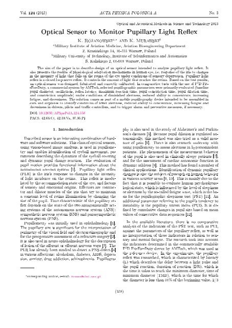
Optical Sensor to Monitor Pupillary Light Reex<br />
K. Ró»anowski a,∗ and K. Murawski b<br />
a Military Institute of Aviation Medicine, Aviation Bioengineering Department<br />
Z. Krasi«skiego 54, 01-755 Warsaw, Poland<br />
b Military University of Technology, Institute of Teleinformatics and Automatics<br />
S. Kaliskiego 2, 00-908 Warsaw, Poland<br />
The aim of the paper is to describe design of an optical sensor intended to analyze pupillary light reex. It<br />
also presents the results of physiological adaptation mechanisms in human eye, i.e. response of the iris to changes<br />
in the intensity of light that falls on the retina of the eye under conditions of sensory deprivation. Pupillary light<br />
reex is a closed loop nerve reex. It controls the amount of light that reaches the retina. Based on the test results,<br />
an optical sensor was designed, fabricated and correctly calibrated. In comparative tests with the use of F 2 D Fit-<br />
-For-Duty, a commercial system by AMTech, selected pupillographic parameters were primarily evaluated (baseline<br />
pupil diameter, oscillations, reex latency, maximum reaction time, pupil constriction time, pupil dilation time,<br />
and constriction amplitude) under conditions of diminished alertness, reduced ability to concentrate, increasing<br />
fatigue, and drowsiness. The solution comes as part of a mobile pupillography device intended to be assembled in<br />
cars and airplanes to identify conditions of lower alertness, reduced ability to concentrate, increasing fatigue and<br />
drowsiness in drivers, pilots and trac controllers, and to trigger alarm and preventive measures, if necessary.<br />
DOI: 10.12693/APhysPolA.124.558<br />
PACS: 42.66.Ct, 42.30.Va, 07.05.Pj<br />
1. Introduction<br />
Described sensor is an interesting combination of hardware<br />
and software solutions. This class of optical sensors,<br />
using vision-based image analysis, is used in pupillometry<br />
and enables identication of eyeball movement, parameters<br />
describing the dynamics of the eyeball covering<br />
and dynamic pupil change reaction. The evaluation of<br />
pupil motion provides functional information about the<br />
autonomous nervous system [1]. Pupillary light reex<br />
(PLR) is the iris's response to changes in the intensity<br />
of light incidence on the retina. This reex is modulated<br />
by the accommodation state of the eye, and factors<br />
of sensory and emotional origins. Eectors are contractor<br />
and dilator muscles of the iris that try to maintain<br />
a constant level of retina illumination by changing the<br />
size of the pupil. Time characteristic of the pupillary re-<br />
ex depends on the state of the two antagonistically acting<br />
systems of the autonomous nervous system (ANS):<br />
sympathetic nervous system (SNS) and parasympathetic<br />
nervous system (PNS).<br />
Pupillometry was initially used in ophthalmology [1].<br />
The pupillary size is signicant for the interpretation of<br />
perimetry of the visual eld and electroretinography and<br />
for the preoperative assessment of a refractive surgery [2].<br />
It is also used in neuro ophthalmology for the description<br />
of lesion of the aerent or eerent nervous ways [3]. The<br />
PLR has already been studied to detect a PNS defect [4]<br />
in various aections: alcoholism, diabetes, AIDS, depression,<br />
anxiety, drug addiction, schizophrenia. Pupillogra-<br />
∗ corresponding author; e-mail: krozan@wiml.waw.pl<br />
phy is also used in the study of Alzheimer's and Parkinson's<br />
diseases [5]. Because pupil dilation is regulated autonomically,<br />
this method was also tried as a valid measure<br />
of pain [6]. There is also research underway with<br />
using pupillometry to assess alertness in hypersomnolent<br />
patients. The phenomenon of the measurement behavior<br />
of the pupil is also used in clinically sleepy patients [7],<br />
and for the assessment of cardiac autonomic function in<br />
dynamic athletes [8]. This method has found a number of<br />
clinical applications. Identication of dynamic pupillary<br />
changes is also the subject of research on human behavior<br />
in various activity areas [9, 10]. This is mainly due to the<br />
fact that it is possible to evaluate human psychophysiological<br />
state, which is inuenced by the level of sleepiness<br />
or alertness by the so-called fatigue wave, which is the basis<br />
for the pupillographic sleepiness test (PST) [11]. An<br />
additional parameter referring to the pupil's tendency to<br />
instability is the pupillary unrest index (PUI). It is de-<br />
ned by cumulative changes in pupil size based on mean<br />
values of consecutive data sequences [12].<br />
In the available literature, there is no comparative<br />
analysis of the indicators of the PST test, such as PUI,<br />
against the parameters of the pupillary reex, as well as<br />
no interpretation of these indicators in relation to sensory<br />
and mental fatigue. The research took into account<br />
the indicators determined in the commercially available<br />
F 2 D Fit-For-Duty device by AMTech, which was used as<br />
the reference device. In the experiments, the pupillary<br />
reex was researched, which is characterized by latency<br />
(L) which describes the delay between a light pulse and<br />
the pupil reaction, duration of reaction (DR), which is<br />
the time it takes to reach the minimum diameter, time of<br />
minimum diameter (TMD), which is the time for which<br />
the diameter is less than 50% of the beginning value, 2/3<br />
(558)
Optical Sensor to Monitor Pupillary Light Reex 559<br />
contraction interval (2/3CI), which is the time for which<br />
the amplitude reaches 1/3 of the contraction phase value,<br />
1/3 redilatation interval (1/3RI), which represents the<br />
time for which the amplitude reaches 1/3 of the redilatation<br />
phase value, and nally amplitude (A), which represents<br />
the dierence between the maximum and minimum<br />
values of the diameter.<br />
2. Description of the experimental model<br />
and the test stand<br />
Design of the sensor for measuring PLR and PST as<br />
well parameters of the eyelid covering the eyeball were<br />
preceded by laboratory tests. The purpose of the research<br />
was to verify the possibility of identication of<br />
time-varying PLR behavior in relation to the PUI factor<br />
described in the literature. At the same time, the requirements<br />
for the designed optical sensor were collected. The<br />
resolution of the converter, frequency of image acquisition<br />
and required speed of the pupil detection algorithm<br />
were taken into account.<br />
The study was conducted in two stages. The rst step<br />
was research where assumptions were veried. The second<br />
stage consisted of a study of the designed PLR sensor.<br />
The rst phase of the study was preceded with a<br />
series of experimental research of the commercially available<br />
F 2 D Fit-For-Duty device by AMTech. The experimental<br />
model assumed verication of PLR parameter<br />
usability in correlation with results of the pupillography<br />
sleepiness test PST. Research was performed on a group<br />
of 10 volunteers in a laboratory environment during at<br />
night. The average age of participants was 34.8 ± 6.5<br />
years. Each participant was familiarized with the description<br />
of the experiment and agreed to participate in<br />
the study. The PLR measurements were taken on both<br />
eyeballs, which were exposed to a series of ve ashes<br />
with the interval of 30 s. The second phase of the experiment<br />
involved testing the constructed PLR sensor.<br />
Functional tests were also carried out on a group of 10<br />
volunteers. The study took place in an ophthalmology<br />
darkroom, which provided necessary conditions for testing.<br />
Measurements were performed in the identical measurement<br />
workow, as in the case of pilot studies [13].<br />
3. Test results<br />
Initial results showed high usability of the dedicated<br />
parameters characteristic for the PLR in estimating the<br />
level of fatigue and lowered concentration, as well as<br />
high correlation with the PUI index (Table I). Statistical<br />
analysis was performed using conventional statistical<br />
methods based on variance analysis. They were multi-<br />
-dimensional, multi-factor analyses of identiable variables<br />
from the pupillary reex signal, categorized by Person,<br />
Task, Eye variables and the light excitation sequence<br />
(Prole). In the subsequent measurement times, parameters<br />
were estimated that described the relative amplitude<br />
and contraction velocity of the pupillary reex (Table II).<br />
Measurements for each person were made four times with<br />
the average interval of 2 h between hours 11.00 PM and<br />
6.30 AM. These changes proved to be statistically significant.<br />
Investigations shown that the dierence between the<br />
rst and last measurement point is 3.07%. With the average<br />
value of the observed changes in pupil width of<br />
1.77 mm, the required measurement accuracy could not<br />
be less than 0.09 mm. This value is necessary to design<br />
the sensor in order to observe the changes in the work<br />
of the ANS for the experimental model adopted. It was<br />
necessary to analyze the behavior of the contraction velocity<br />
parameter in order to determine the required speed<br />
of the optical system. The scope of averaged parameter<br />
values for the rst and last measurement was 0.5 mm/s.<br />
It means that the measurement resolution cannot be less<br />
than 0.25 mm/s. These assumptions were adopted in the<br />
design of the PLR optical sensor.<br />
TABLE I<br />
Table showing the values of the rPUI and rPUI rel parameters<br />
in successive measurement points.<br />
rPUI<br />
rPUI rel<br />
task N mean st.d. mean st.d.<br />
All 398 0.83 0.42 0.20 0.29<br />
0 99 0.62 0.25 0.00 0.00<br />
1 102 0.76 0.35 0.13 0.15<br />
2 98 0.91 0.40 0.28 0.17<br />
3 99 1.02 0.55 0.39 0.45<br />
TABLE II<br />
Table showing the values of the relative amplitude<br />
and contraction velocity indicators in successive<br />
measurement points.<br />
Rel. amplitude Contr. velocity<br />
Task N mean st.d. mean st.d.<br />
0 79 24.21 5.11 3.98 0.82<br />
1 76 25.53 5.28 4.21 0.89<br />
2 80 26.22 5.36 4.29 0.83<br />
3 79 27.28 5.47 4.49 0.87<br />
4. Optical sensor to monitor pupillary<br />
light reex<br />
In pupillary light reex testing, it is most important<br />
to determine the parameters of pupil response to light<br />
stimulation with a specic duration (t = 250 ms). The<br />
measurement method for PLR determines the design of<br />
the illuminator control system, image acquisition system<br />
and software. In the adopted implementation the change<br />
of pupil size in time is determined by analyzing the motion<br />
camera image. The acquired image is recorded in the<br />
near-infrared band (λ = 850 nm) by the Optitrack V120<br />
camera. The red KPTD-3216SURC LED with the wavelength<br />
of λ = 640 nm was used as an excitation source.
560 K. Ró»anowski, K. Murawski<br />
Near-infrared light was used because of the lack of eect<br />
on the pupil. The choice of red light as the excitation was<br />
intuitive. There is no clear information in the literature<br />
that would help determine the color of the LED generating<br />
the light pulse (excitation). This research is still<br />
underway. The control system was separated from the<br />
illuminator plate in the device. The adopted solution, by<br />
changing the illuminator plate, enables to examine the<br />
behavior of the pupil at dierent light wavelengths. The<br />
control system was designed as a microcomputer system<br />
controlled by the RS-485 bus. The RS-485 bus is controlled<br />
by the AT89s8253 microcontroller. It receives and<br />
executes commands issued from the host system (IBM<br />
PC type computer). These commands are encoded by<br />
the system and transmitted through the I2C bus to the<br />
peripheral device. The PCA 9622DR LED control circuit<br />
made by NXP Semiconductor was used as the peripheral<br />
device. This circuit is a specialized controller of<br />
sixteen channels of light-emitting diodes, LED0LED15.<br />
It enables selective brightness control for each channel.<br />
Brightness control is achieved by choosing the parameters<br />
of pulse width generators (PWM0PWM15). An<br />
external resistor in series with the LED circuit sets the<br />
maximum current in the channel. This current should<br />
not exceed 100 mA at an input voltage of up to 40 V.<br />
The application used fourteen of the sixteen available<br />
channels. Each of them has a branch of LED supplied<br />
with a voltage of U Z = +5 V.<br />
Twelve HIRB5-43G-A infrared LEDs and two KPTD-<br />
-3216SURC LEDs operating in the visible spectrum were<br />
placed on a separate printed circuit board. It is connected<br />
to the illuminator plate with the FFC elastic tape<br />
from Molex (MX-98266-0193). Visible light LEDs are<br />
used for excitation and communicating with the tested<br />
person. LEDs operated in the infrared spectrum, as the<br />
illuminator with almost any congurable layout and intensity<br />
of light. The resulting sensor was tested in a<br />
system with and without the infrared mirror. Experiments<br />
were carried out in a darkroom due to the need<br />
to isolate the pupil from the outside light. Ultimately,<br />
after the construction of the head-mounted housing, the<br />
sensor will operate in the infrared mirror conguration.<br />
Such a conguration will provide for greater exibility<br />
and repeatability of tests, Figs. 1 and 2.<br />
Software was developed for the constructed design to<br />
automatically search the pupil in the image, Fig. 3. The<br />
pupil searching algorithm uses techniques described in<br />
Refs. [1416]. After nding the pupil, its size (width and<br />
height) is measured. Finally, because of the lower sensitivity<br />
to interference due to eyelid movements, the value<br />
equal to the width of the pupil is presented as a result of<br />
the measurement. The software measures the pupil size<br />
with the interval of t = 40 ms (25 fps). Without modifying<br />
the image processing algorithms, this value can be reduced<br />
to t = 10 ms. As a result, measurement of changes<br />
in pupil size will be performed at a frequency of one hundred<br />
frames per second (100 fps). The time t = 40 ms<br />
was used because of the parameters of the reference de-<br />
Fig. 1. The images of selected illuminator layouts:<br />
change in the layout of active LEDs (a)(c), selective<br />
power control for each channel (d).<br />
Fig. 2. Sensor operating layouts: without a mirror (a),<br />
with the infrared mirror (b).<br />
vice F 2 D Fit-For-Duty by AMTech, which analyzes the<br />
image at the rate of 25 fps.<br />
Fig. 3. View of the application interoperating with the<br />
PLR testing sensor.<br />
The PLR measurement is performed by pressing the<br />
Pulse button. The software automatically generates a<br />
light pulse with a duration of t = 250 ms, and then identies<br />
and saves the changes in pupil size over 2 s. Also,<br />
a video showing behavior of the pupil during the measurement<br />
is recorded for documentation purposes. The<br />
software allows for working with and without calibrating<br />
the camera's optical system. Without calibration, it<br />
is possible to determine absolute or relative changes in
pupil size. Absolute pupil sizes are measured in pixels<br />
(pix.), Fig. 4a. Relative values do not have a unit of<br />
measure, and they are in the (0, 1) range, Fig. 4b. In<br />
this case, the starting point for calculations is the highest<br />
measured pupil size. In such a conguration, 1 means<br />
the largest and 0 means the smallest pupil size.<br />
Optical Sensor to Monitor Pupillary Light Reex 561<br />
Fig. 6. Template (decreased) for the calibration of the<br />
measurement system (a) and measurement result (b).<br />
Fig. 4. Sample results of PLR measurements: absolute<br />
measurement in pix. (a) and relative (b).<br />
Calibration allows for measuring the pupil size in millimeters.<br />
The procedure involves placing the object of<br />
known size in front of the sensor and pressing the Calibration<br />
button. The software will automatically search<br />
for an object similar to the shape of the pupil, measure<br />
and determine the number of millimeters per one pixel<br />
of the image. In order to maintain measurement accuracy<br />
during both calibration and normal operation, it is<br />
required that the contrast in the image was similar. For<br />
this purpose, the software implements a procedure for determining<br />
the contrast used in stills cameras (maximum<br />
contrast method), Fig. 5a.<br />
Fig. 7. Results of the test measurement of template<br />
elements.<br />
10.0531 mm, 8 mm 8.0708 mm, 6 mm 6.0177 mm,<br />
4 mm 4.0708 mm, 2 mm 2.0531 mm, Fig. 7.<br />
As a result, the average measurement error for patterns<br />
was found to be 0.0442 mm. This was followed by<br />
measuring changes in pupil size as a function of time after<br />
excitation with a red light pulse, Fig. 8. The results<br />
obtained show that the developed sensor can objectively<br />
assess pupil reaction to a stimulus in the form of a red<br />
light pulse. It also enables measurement of the variability<br />
range of pupil contraction, expressed in millimeters,<br />
as well as in relative and absolute manner.<br />
Fig. 5. Contrast measurement: principle of operation<br />
(a), location of the probes (b).<br />
Contrast measurement is carried out using two probes<br />
placed on the left and right side of the pupil, Fig. 5b. Luminance<br />
values of pixels contained in the left and right<br />
part of the probe are summed for each image frame. Then<br />
the corresponding average luminance values A and B<br />
are determined. The result of the measurement suggests<br />
moving the camera so as to maximize the value<br />
of |A − B|. The optical system was calibrated using the<br />
template shown in Fig. 6a and b.<br />
A circle with a diameter of 12 mm was selected from<br />
the template. After the calibration, the obtained measurement<br />
step for this diameter was 0.035398 mm. Next,<br />
the software was switched to the Measurement mode,<br />
and a test measurement was made. The resulting value<br />
for the pattern was 12 mm. For other elements of the<br />
template, the following values were obtained: 10 mm <br />
Fig. 8. Changes in pupil size as a function of time after<br />
the sequential (5×) excitation with a red light pulse<br />
expressed in mm.<br />
Another important aspect was the safety of the sensor.<br />
Therefore, the IR illuminator of the sensor was tested and<br />
the results are shown in [17].<br />
5. Conclusions<br />
The tests provided an overview of the design requirements<br />
for the PLR optical sensor. They provided a<br />
guidance for the design of a system for detecting and<br />
identifying dynamic changes in the pupillary type re-<br />
ex system. The designed proprietary optical sensor allowed<br />
for obtaining the required image acquisition speed
562 K. Ró»anowski, K. Murawski<br />
(25 to 120 fps) and sucient measurement accuracy<br />
(0.0442 mm). In practice, in the absence of a head-<br />
-mounted housing, the only restriction on its use is the<br />
need for a darkroom. Along with the sensor, the authors<br />
have developed software capable of immediate visualization<br />
of the PLR reex and video acquisition for documentation<br />
purposes.<br />
The solution comes as part of a mobile pupillography<br />
device intended to be assembled in cars and airplanes to<br />
identify conditions of lower alertness, reduced ability to<br />
concentrate, increasing fatigue and drowsiness in drivers,<br />
pilots and trac controllers, and to trigger alarm and<br />
preventive measures, if necessary [18].<br />
Acknowledgments<br />
The project was co-nanced by the European Union<br />
through the European Regional Development Fund under<br />
the Innovative Economy Program. Development Project<br />
contract no. POIG.01.03.01-10-085/09.<br />
References<br />
[1] Ch. Tilmant, M. Charavel, M. Ponrouch, Monitoring<br />
and Modeling of Pupillary Dynamics: Study of the<br />
Autonomous Nervous System, Blaise Pascal University,<br />
OICMS France 2005.<br />
[2] R.J. Duey, D. Leaming, J. Refract. Surg. 21, 87<br />
(2005).<br />
[3] I. Loewenfeld, O. Lowenstein, Anatomy, Physiology,<br />
and Clinical Applications, Iowa State University<br />
Press, Ames 1993.<br />
[4] A. Kawasaki, R.H. Kardon, Ophthalmol. Clin. North<br />
Am. 14, 149 (2001).<br />
[5] D.F. Fotiou, V. Stergioua, D. Tsiptsiosa, C. Litharib,<br />
M. Nakouc, A. Karlovasitoua, Int. J. Psychophysiol.<br />
73, 143 (2009).<br />
[6] M. Höe, R. Kenntner-Mabiala, P. Pauli,<br />
G.W. Alpers, J. Psychophysiol. 70, 171 (2008).<br />
[7] J.W. McLaren, P.J. Hauri, Siong-Chi Lin, C. Harris,<br />
Sleep Medicine 3, 347 (2002).<br />
[8] A. Kaltsatou, E. Kouidi, C. Lithari, N. Koutlianos,<br />
F. Fotiou, A. Deligiannis, Int. J. Psychophysiol. 77,<br />
283 (2010).<br />
[9] B. Wilhelm, A. Widmann, W. Durst, Ch. Heine,<br />
G. Otto, Int. J. Psychophysiol. 72, 307 (2009).<br />
[10] M. Warga, H. Lüdtke, H. Wilhelm, B. Wilhelm, Vision<br />
Res. 49, 295 (2009).<br />
[11] O. Lowenstein, R. Feinberg, I.E. Loewenfeld, Investigat.<br />
Ophthalmol. 2, 138 (1963).<br />
[12] B. Wilhelm, H. Wilhelm, P. Streicher, H. Lüdtke,<br />
M. Adler, Wien Med. Wochenschr. 146, 387 (1996).<br />
[13] K. Murawski, K. Ró»anowski,<br />
124, 509 (2013).<br />
Acta Phys. Pol. A<br />
[14] K. Gut, K. Nowak, Europ. Phys. J. Spec. Top. 154,<br />
89 (2008).<br />
[15] K. Murawski, in: Proc. XV Int. Conf. on Methods<br />
and Models in Automation and Robotics (MMAR),<br />
[16]<br />
Mi¦dzyzdroje, Warsaw Univ., 2010, p. 356.<br />
K. Gut, Bull. Pol. Acad. Sci., Techn. Sci. 59, 395<br />
(2011).<br />
[17] M. ›yczkowski, Acta Phys. Pol. A 122, 933 (2012).<br />
[18] K. Murawski, Electrotechn. Rev. 9, 184 (2010).