Full Text PDF
Full Text PDF
Full Text PDF

Create successful ePaper yourself
Turn your PDF publications into a flip-book with our unique Google optimized e-Paper software.
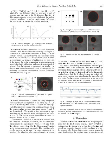
pupil size. Absolute pupil sizes are measured in pixels<br />
(pix.), Fig. 4a. Relative values do not have a unit of<br />
measure, and they are in the (0, 1) range, Fig. 4b. In<br />
this case, the starting point for calculations is the highest<br />
measured pupil size. In such a conguration, 1 means<br />
the largest and 0 means the smallest pupil size.<br />
Optical Sensor to Monitor Pupillary Light Reex 561<br />
Fig. 6. Template (decreased) for the calibration of the<br />
measurement system (a) and measurement result (b).<br />
Fig. 4. Sample results of PLR measurements: absolute<br />
measurement in pix. (a) and relative (b).<br />
Calibration allows for measuring the pupil size in millimeters.<br />
The procedure involves placing the object of<br />
known size in front of the sensor and pressing the Calibration<br />
button. The software will automatically search<br />
for an object similar to the shape of the pupil, measure<br />
and determine the number of millimeters per one pixel<br />
of the image. In order to maintain measurement accuracy<br />
during both calibration and normal operation, it is<br />
required that the contrast in the image was similar. For<br />
this purpose, the software implements a procedure for determining<br />
the contrast used in stills cameras (maximum<br />
contrast method), Fig. 5a.<br />
Fig. 7. Results of the test measurement of template<br />
elements.<br />
10.0531 mm, 8 mm 8.0708 mm, 6 mm 6.0177 mm,<br />
4 mm 4.0708 mm, 2 mm 2.0531 mm, Fig. 7.<br />
As a result, the average measurement error for patterns<br />
was found to be 0.0442 mm. This was followed by<br />
measuring changes in pupil size as a function of time after<br />
excitation with a red light pulse, Fig. 8. The results<br />
obtained show that the developed sensor can objectively<br />
assess pupil reaction to a stimulus in the form of a red<br />
light pulse. It also enables measurement of the variability<br />
range of pupil contraction, expressed in millimeters,<br />
as well as in relative and absolute manner.<br />
Fig. 5. Contrast measurement: principle of operation<br />
(a), location of the probes (b).<br />
Contrast measurement is carried out using two probes<br />
placed on the left and right side of the pupil, Fig. 5b. Luminance<br />
values of pixels contained in the left and right<br />
part of the probe are summed for each image frame. Then<br />
the corresponding average luminance values A and B<br />
are determined. The result of the measurement suggests<br />
moving the camera so as to maximize the value<br />
of |A − B|. The optical system was calibrated using the<br />
template shown in Fig. 6a and b.<br />
A circle with a diameter of 12 mm was selected from<br />
the template. After the calibration, the obtained measurement<br />
step for this diameter was 0.035398 mm. Next,<br />
the software was switched to the Measurement mode,<br />
and a test measurement was made. The resulting value<br />
for the pattern was 12 mm. For other elements of the<br />
template, the following values were obtained: 10 mm <br />
Fig. 8. Changes in pupil size as a function of time after<br />
the sequential (5×) excitation with a red light pulse<br />
expressed in mm.<br />
Another important aspect was the safety of the sensor.<br />
Therefore, the IR illuminator of the sensor was tested and<br />
the results are shown in [17].<br />
5. Conclusions<br />
The tests provided an overview of the design requirements<br />
for the PLR optical sensor. They provided a<br />
guidance for the design of a system for detecting and<br />
identifying dynamic changes in the pupillary type re-<br />
ex system. The designed proprietary optical sensor allowed<br />
for obtaining the required image acquisition speed