D-Cinema and Automation: Joining Two Worlds - Kinoton
D-Cinema and Automation: Joining Two Worlds - Kinoton
D-Cinema and Automation: Joining Two Worlds - Kinoton
- TAGS
- worlds
- kinoton
- www.kinoton.de

Create successful ePaper yourself
Turn your PDF publications into a flip-book with our unique Google optimized e-Paper software.
Dear <strong>Kinoton</strong> Customers,<br />
Business Partners, <strong>and</strong> Colleagues,<br />
The last issue of “<strong>Kinoton</strong> Special” explained<br />
how a theatre management system (TMS)<br />
works. The main purpose of a TMS is managing<br />
digital film copies <strong>and</strong> distributing them<br />
among the servers or auditoriums of a cinema<br />
center or multiplex.<br />
Although server playlists let you program the<br />
basic functions of shows, until recently there<br />
were few if any possibilities for (remotely) controlling<br />
all of the devices in projection booths<br />
<strong>and</strong> all auditorium systems from different places<br />
in the theatre. In particular, it was difficult to<br />
integrate existing cinema automation systems.<br />
While designing <strong>and</strong> developing our new digital<br />
cinema automation system, we paid especially<br />
great attention to ensuring its flexibility <strong>and</strong><br />
modularity for use with virtually any combination<br />
of equipment, including older models. One<br />
outst<strong>and</strong>ing benefit of our automation system<br />
is that in most cases, it lets you reuse existing<br />
wiring, for example for auditorium control.<br />
If you have any questions, your local <strong>Kinoton</strong><br />
sales <strong>and</strong> service partner will be glad to answer<br />
them.<br />
Sincerely,<br />
Christoph Dobler<br />
CEO of <strong>Kinoton</strong> GmbH<br />
D-<strong>Cinema</strong> <strong>and</strong> <strong>Automation</strong>:<br />
<strong>Joining</strong> <strong>Two</strong> <strong>Worlds</strong><br />
Special<br />
Edition for CineEurope 2011<br />
As digitization has swept the industry, more <strong>and</strong> more movie theatres have installed new equipment<br />
<strong>and</strong> upgraded existing components <strong>and</strong> systems. However, seamlessly integrating the newly<br />
installed digital cinema projectors, servers, <strong>and</strong> alternative content players with conventional<br />
auditorium functions is quite a challenge for conventional automation systems. Modular, decentralized<br />
theatre automation systems can come to the rescue. They ensure fast, cost-effective,<br />
all-encompassing system integration while providing the greatest possible flexibility for adding<br />
hardware <strong>and</strong> features later.<br />
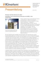
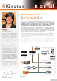
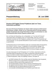
Conventional cinema automation systems are based on a central matrix programmer machine. Each individual<br />
function of every connected component requires a separate signal line to the central machine <strong>and</strong><br />
yet another line to at least one control panel in the projection booth <strong>and</strong>/or auditorium. If more control functions<br />
are added later, they also have to be wired <strong>and</strong> connected to the central machine. The resulting dense<br />
web of wiring <strong>and</strong> complex connections incur high costs for materials, <strong>and</strong> it is time-consuming to install <strong>and</strong><br />
commission these systems. The work is additionally complicated by the use of nonst<strong>and</strong>ard GPIO interfaces<br />
(see the information box on page 4).<br />
Auditorium light<br />
control wall/ceiling<br />
Stage light control<br />
Audio processor<br />
analog/digital<br />
Masking control<br />
Curtain drawing<br />
control<br />
Figure 1: Layout of a centralized automation system<br />
Server<br />
Central<br />
automation<br />
device<br />
Door locking<br />
system<br />
Projection room<br />
control panel<br />
Auditorium<br />
control panel 1<br />
Auditorium<br />
control panel 2<br />
To make matters even worse, cinema automation systems with a centralized structure are usually based on<br />
relays, even when they are computer-controlled. But a central automation device can only hold a limited<br />
number of these electromagnetic switches, which makes it difficult or impossible to extend its functionality,<br />
especially if the aim is to integrate D-<strong>Cinema</strong> technology.<br />
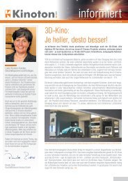
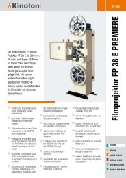
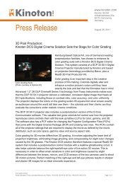
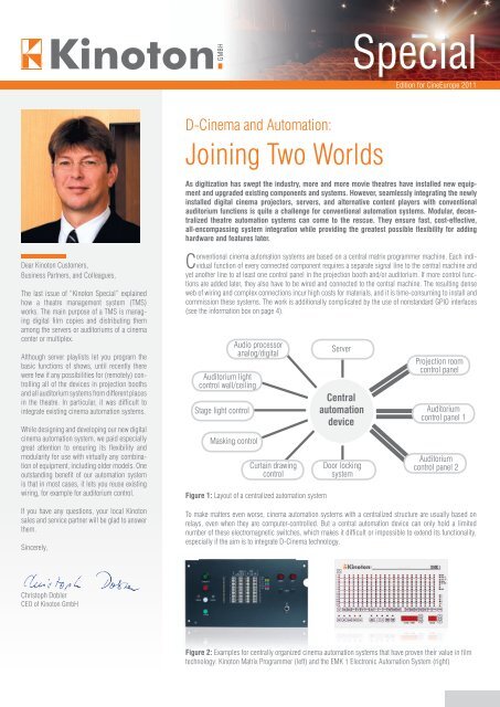
Figure 2: Examples for centrally organized cinema automation systems that have proven their value in film<br />
technology: <strong>Kinoton</strong> Matrix Programmer (left) <strong>and</strong> the EMK 1 Electronic <strong>Automation</strong> System (right)
Decentralization Opens Up New Vistas<br />
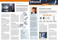
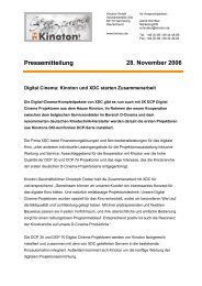
The latest-generation automation systems avoid these problems by dispensing with central control. They are characterized by a distributed system<br />
architecture with a single, common data line or bus that links together cinema components such as servers, sound processors, <strong>and</strong> light control circuits.<br />
The new decentralized <strong>Kinoton</strong> DCA Digital <strong>Cinema</strong> <strong>Automation</strong> system, for example,<br />
quickly <strong>and</strong> securely transfers data via what is called a CAN-bus system<br />
(see information box 2). The CAN-bus is the spinal cord of the DCA system.<br />
It doesn’t require a central junction box or complex wiring. <strong>Cinema</strong> technology<br />
components for automation are simply connected to the CAN-bus in any order<br />
using installation modules. Each connection only needs four lines: two signal<br />
lines, a ground line, <strong>and</strong> a power supply line (see Figure 5).<br />
Via the shared data bus, all of the connected components send <strong>and</strong> receive protocols<br />
that trigger the desired control functions. This system has major advantages.<br />
You can exactly calculate in advance the amount <strong>and</strong> cost of required hardware,<br />
such as interfaces <strong>and</strong> cables. Usually far fewer materials are also needed,<br />
since you don’t need to perform any of the complicated individual adaptions that<br />
are often necessary with conventional central automation. The system is quick<br />
<strong>and</strong> easy to install, thus saving you a lot of time <strong>and</strong> money. It is also a cinch to<br />
extend the CAN-bus at any time to integrate upgraded equipment versions <strong>and</strong><br />
enhancements. This makes the DCA system a forward-looking investment that<br />
delivers enormous value for money.<br />
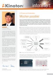
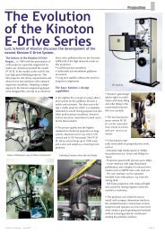
Because the DCA Digital <strong>Cinema</strong> <strong>Automation</strong> can seamlessly integrate digital<br />
cinema technology with existing auditorium functions, the system is perfectly<br />
transparent to the user <strong>and</strong> very easy to operate. For example, before now projectionists<br />
preparing a show playlist (SPL) at a D-<strong>Cinema</strong> server always had to keep<br />
in mind how each function had been implemented in the system. Comm<strong>and</strong>s<br />
affecting the D-<strong>Cinema</strong> system had to be different from those for peripheral functions<br />
such as room lighting or the masking system – a constant source of error.<br />
With the DCA system, operators simply choose from clearly named automation<br />
comm<strong>and</strong>s, thus eliminating confusion <strong>and</strong> preventing problems.<br />
Figure 3: Control panel in the projection booth<br />
Auditorium light<br />
control wall/ceiling<br />
Figure 5: Layout of a decentrally organized automation system<br />
Modules for Easy System<br />
Integration<br />
The DCA Digital <strong>Cinema</strong> <strong>Automation</strong> has flexible interface modules that permit<br />
quick <strong>and</strong> easy connection of various cinema components. The modules convert<br />
signals from the components into CAN-bus signals <strong>and</strong> ensure flawless data<br />
transfer. All automation modules can be quickly <strong>and</strong> easily connected to the<br />
CAN-bus using identical Phoenix connectors. Diagnostic LEDs on each module<br />
provide constant information about its operating status. In addition, each module<br />
has a st<strong>and</strong>ard CAN-CiA-compliant diagnostic connector (9-pin D-Sub) that<br />
qualified service engineers can use to control the CAN-bus signals.<br />
The server module forms a bridge between the D-<strong>Cinema</strong> server <strong>and</strong> the <strong>Kinoton</strong><br />
CAN-bus, thus making sure that all peripheral functions (curtain motors, room<br />
lighting, stage lighting, etc.) can be conveniently controlled from the server. The<br />
server module is compatible with all common server models. Doremi servers, for<br />
example, communicate with the server module over the D-<strong>Cinema</strong> network (Ethernet),<br />
<strong>and</strong> Dolby models are connected via a serial interface (RS232). The comm<strong>and</strong>s<br />
of the D-<strong>Cinema</strong> server are transmitted as short digital codes called control<br />
strings. They are the same for all server types <strong>and</strong> specifically programmed<br />
by <strong>Kinoton</strong> for this. If necessary, more control strings can be defined to add more<br />
unusual control tasks to the system.<br />
Various audio modules are available for integrating CP750, CP650, <strong>and</strong> CP500<br />
Dolby sound processors into the DCA system. The connector pin assignments<br />
Data bus line<br />
Audio processor<br />
Server<br />
analog/digital<br />
<strong>Cinema</strong> automation<br />
Figure 4: Control panel in the auditorium<br />
Stage light control Masking control Curtain drawing<br />
control<br />
Auditorium<br />
control panel<br />
Door locking<br />
system<br />
Projection room<br />
control panel<br />
Freely exp<strong>and</strong>able<br />
Integration of existing cinema automation<br />
in case of retrofitting
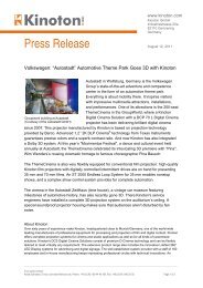
Power<br />
supply<br />
Server<br />
Module<br />
alternatively, depending on<br />
server type<br />
D-<strong>Cinema</strong><br />
server<br />
HD-SDI<br />
D-<strong>Cinema</strong><br />
projector<br />
Auditorium light<br />
control wall/ceiling<br />
Relay<br />
Module 1<br />
Network<br />
switch<br />
Audio<br />
Module<br />
Relay<br />
Module 2<br />
Figure 6: Seamless integration of D-<strong>Cinema</strong> technology <strong>and</strong> auditorium functions in the <strong>Kinoton</strong> DCA Digital <strong>Cinema</strong> <strong>Automation</strong> system<br />
of the module interfaces correspond to the Dolby conventions, so in most cases<br />
no additional adapters are required. The connection module is mounted in the<br />
sound rack <strong>and</strong> controls the cinema processor <strong>and</strong> auxiliary audio devices such<br />
as the <strong>Kinoton</strong> DMI Digital Media Interface <strong>and</strong> the Dolby DMA8-Plus. This ensures<br />
system-wide signal consistency <strong>and</strong> lets you uniformly control the volume<br />
levels <strong>and</strong> sound formats of all audio processors via the auditorium panel or the<br />
control panel in the projection booth. This even applies to analog cinema processors<br />
such as the Dolby CP65, which can be easily connected to the DCA Digital<br />
<strong>Cinema</strong> <strong>Automation</strong> system using a special analog audio module.<br />
The <strong>Kinoton</strong> CAN-bus supports up to six D-<strong>Cinema</strong> control panels <strong>and</strong> six D-<br />
<strong>Cinema</strong> auditorium panels that let you manually control the connected cinema<br />
equipment from the projection booth or auditorium. Each panel has 20 illuminated<br />
<strong>and</strong> labeled pushbuttons, each of which can be assigned to two different<br />
functions. A shift key lets you conveniently switch between the two functions. The<br />
color of each button’s light can be individually configured. You can conveniently<br />
<strong>and</strong> accurately control the volume using a dial with a digital display. It isn’t even<br />
necessary to carry a physical key to enable control panels; instead, you can<br />
activate them simply by pressing a special key combination.<br />
Room functions such as lighting, opening <strong>and</strong> closing of curtains, masking, <strong>and</strong><br />
door locking systems are connected to the <strong>Kinoton</strong> CAN-bus via relay modules.<br />
This lets you integrate not only the latest auditorium technology, but also any<br />
older system requiring 230-volt control. Each relay module has eight relays for<br />
directly connecting devices. The <strong>Kinoton</strong> CAN bus supports up to 10 relay modules,<br />
so when it is equipped with the maximum number you have a total of 80<br />
relays at your disposal. All relays can be configured as “normally closed” (NC)<br />
or “normally open” (NO) contacts as required. In addition, each relay module<br />
comes with three switch inputs on which you can mount control buttons for the<br />
basic server functions Start, Stop, <strong>and</strong> Pause. This lets you remotely control<br />
any D-<strong>Cinema</strong> server in the theatre from any relay module simply by pressing<br />
a button.<br />
If you retrofit the DCA system, it seamlessly integrates with existing automation<br />
functions. <strong>Kinoton</strong> automation systems are especially easy to connect to<br />
the <strong>Kinoton</strong> CAN-bus, thanks to the interface module. Over 20 configurable relay<br />
contacts are available for this purpose. Just like the relay modules, the inter-<br />
Stage light control Masking control Curtain drawing<br />
control<br />
Audio processor<br />
analog/digital<br />
<strong>Kinoton</strong> CAN-Bus<br />
Relay<br />
Module 3<br />
Interface<br />
Module<br />
<strong>Cinema</strong> automation<br />
Relay<br />
Module 4<br />
Auditorium<br />
control panel<br />
Door locking<br />
system<br />
Relay<br />
Module 5<br />
Projection room<br />
control panel<br />
<strong>Kinoton</strong> DCA Digital <strong>Cinema</strong> <strong>Automation</strong><br />
Other signal lines<br />
Integration of existing cinema automation<br />
in case of retrofitting<br />
face module provides three switch inputs for remotely controlling the D-<strong>Cinema</strong><br />
server (Start, Stop, Pause).<br />
The range of additional modules for the DCA Digital <strong>Cinema</strong> <strong>Automation</strong> is growing.<br />
The following modules are currently available:<br />
DCA Modules Code Number<br />
DCA Module „DOREMI Server“ 0070 363 01001<br />
DCA Module „DOLBY Server“ 0070 363 01002<br />
DCA Module „CP 750 / DMA 8 (plus) / DMI“ 0070 363 02001<br />
DCA Module „CP 650 / DMA 8 (plus) / DMI“ 0070 363 02002<br />
DCA Module „CP 500 / DMA 8 (plus) / DMI“ 0070 363 02003<br />
DCA Module „CP 65 / CP 55 / DMA 8 (plus) / DMI“ 0070 363 02004<br />
DCA Module „DMS Scaler / Alternative Content“ 0070 363 03001<br />
DCA Module „Control Panel Interface FP 30“ 0070 363 04001<br />
DCA Module „Interface Connection FP 40 / 50“ 0070 363 04002<br />
DCA Module „External Devices – Relay 8 (230 V)“ 0070 363 05001<br />
DCA Module „Auditorium Control Panel“ 0070 363 06001<br />
DCA Module „Projection Room Control Panel“ 0070 363 06002<br />
DCA Module „Fire Alarm / Emergency-Off“ 0070 363 07001<br />
DCA Module „Projector Exhaust Control“ 0070 363 08001<br />
DCA Module „Media Control“ on request<br />
DCA Module „Power Supply 24 V“ 0070 363 10001<br />
DCA Module Installation Kit 0070 363 10005<br />
www.kinoton.com/digitalcinema
Info Box 1: GPIO<br />
The term GPIO (General Purpose Input/Output) originated in the field of microelectronics,<br />
but these days it is also used in control engineering. GPIO<br />
interfaces are not assigned to any specific function <strong>and</strong> are not st<strong>and</strong>ardized<br />
in any way. Every manufacturer of digital cinema technology therefore uses<br />
connectors with varying, arbitrary pin assignments for different connection<br />
values.<br />
This means that there is no universal solution for integrating digital cinema<br />
technology with a conventional cinema automation system. In fact, service<br />
engineers have to work out an individual solution for every installation, depending<br />
on its unique technical characteristics. In addition, it is generally<br />
not possible for a proposed function to be directly triggered via a GPIO input<br />
or output. To accomplish this, additional circuits <strong>and</strong> other adjustments are<br />
needed, <strong>and</strong> in many cases even a separate power supply. As a consequence,<br />
integrating digital cinema technology or adding new features to a cinema<br />
automation system is always a costly, time-consuming, <strong>and</strong> unpredictable<br />
project.<br />
Info Box 2: CAN-Bus<br />
A bus (from the Latin word omnibus = for all) is a system for transferring<br />
data among multiple parties via a shared communication path. CAN is short<br />
for Controller Area Network <strong>and</strong> describes a network or bus system that is<br />
optimized for control tasks. In contrast to the nonst<strong>and</strong>ard GPIO interfaces,<br />
CAN-bus technology conforms to clear stipulations defined in the ISO 11898<br />
st<strong>and</strong>ard. The DCA Digital <strong>Cinema</strong> <strong>Automation</strong> system naturally also complies<br />
with this st<strong>and</strong>ard.<br />
The CAN-bus system was originally developed in the 1980s by Bosch, Intel,<br />
<strong>and</strong> Daimler-Benz to simplify automotive wiring harnesses <strong>and</strong> cut down on<br />
weight. CAN-bus technology lets you send much larger amounts of data over<br />
significantly fewer lines. Moreover, this type of signaling is capable of realtime<br />
transmission, highly immune to electromagnetic interference, extremely<br />
robust, <strong>and</strong> easy to h<strong>and</strong>le. Multiple security mechanisms ensure stable, reliable<br />
data transfer, which has made CAN-bus systems popular not only in the<br />
automotive industry but also in many other, often security-related, applications<br />
including medical <strong>and</strong> aerospace technology.<br />
CAN-bus is a multimaster system in which all connected components have<br />
the same potential. Any faulty component immediately disconnects from the<br />
bus (“bus off”) to avoid blocking the system. The wiring goes in a straight line<br />
between successive components, following a pattern called a line topology.<br />
In principle, any bus component can use the bus to transmit signals at any<br />
time while all other components just “listen”. However, simultaneously transmitting<br />
multiple signals can cause data loss, so components have to take<br />
turns sending their data. Access conflicts are prevented by the subtle CSMA/<br />
CR principle (Carrier Sense Multiple Access/Collision Resolution): Each<br />
message is marked with a short code (identifier) that indicates its importance.<br />
In an “arbitration” phase, the identifiers of all “transmission inquiries”<br />
are compared to define which message is the most important. The relevant<br />
component can then transmit its message instantly <strong>and</strong> without any loss of<br />
data. The principle is therefore also called “loss-free bus arbitration”.<br />
This is also one of the main differences from Ethernet transmission. If several<br />
participants simultaneously try to access the common data line, their messages<br />
are destroyed <strong>and</strong> they all stop transmitting at once. The next transmission<br />
attempt cannot be made until after a brief pause. Obviously, it is not possible to<br />
transmit data in real-time on this basis.<br />
To increase the susceptibility to interference of the CAN-bus system, data are<br />
differentially transmitted via two lines with complementary signal levels. The<br />
receiver determines the signal value from the difference between these two<br />
balanced voltages. Electromagnetic interference, e.g. caused by alternating<br />
current lines, power transformers, or lamp ignition, influences the complementary<br />
signal levels to the same degree <strong>and</strong> is therefore cancelled out when the<br />
difference between the two signals is calculated. The bus cable of the <strong>Kinoton</strong><br />
DCA Digital <strong>Cinema</strong> <strong>Automation</strong> also supplies all bus components with power,<br />
so the installation modules do not need their own power supply units.<br />
Figure 7: Differential CAN-bus signals displayed by a digital oscilloscope: the desired<br />
signal results from the difference between the complementary signals CAN-<br />
High (yellow) <strong>and</strong> CAN-Low (green).<br />
<strong>Kinoton</strong> GmbH<br />
Industriestrasse 20a<br />
82110 Germering, Germany<br />
Tel +49 (0)89 894446-0<br />
Fax +49 (0)89 8402002<br />
welcome@kinoton.de<br />
www.kinoton.com<br />
06/2011. FA/250