Instruction and Operating Manual - AT Controls
Instruction and Operating Manual - AT Controls
Instruction and Operating Manual - AT Controls

Create successful ePaper yourself
Turn your PDF publications into a flip-book with our unique Google optimized e-Paper software.
�<br />
www.a-tcontrols.com<br />
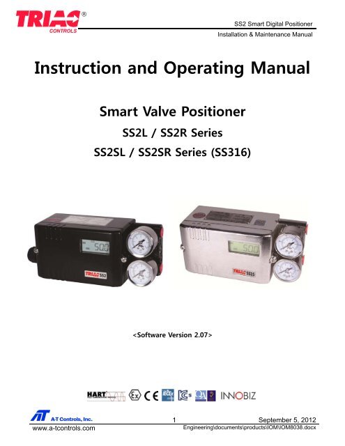
SS2 Smart Digital Positioner<br />
Installation & Maintenance <strong>Manual</strong><br />
<strong>Instruction</strong> <strong>and</strong> <strong>Operating</strong> <strong>Manual</strong><br />
Smart Valve Positioner<br />
SS2L / SS2R Series<br />
SS2SL / SS2SR Series (SS316)<br />
<br />
1 September 5, 2012<br />
Engineering\documents\products\IOM\IOM8038.docx
�<br />
www.a-tcontrols.com<br />
Contents<br />
SS2 Smart Digital Positioner<br />
Installation & Maintenance <strong>Manual</strong><br />
1. Safety <strong>Instruction</strong>s / Precautions 3 11.5.3 Selection of Linear, E.Q.%, Quick Open, User Set (17pts)<br />
2. Overview of Structure 8 11.5.4 Span Adjustment 38<br />
3. Specifications 9 11.5.5 Zero Adjustment<br />
4. Nameplate Descriptions 10 11.5.6 PID-Gain 39<br />
5. Principle of Operation 11.5.6.A P-Gain<br />
6. Descriptions of LCD Display <strong>and</strong> Buttons 11 11.5.6.B I-Gain<br />
7. Installation 12 11.5.6.C D-Gain<br />
7.1 Mounting onto Linear Actuator 11.5.6.D GROP-Gain<br />
7.2 Mounting onto Rotary Actuator 16 11.5.7 Control Speed adjustment 41<br />
8. Air Connections 19 11.5.7.A SPEED<br />
8.1 SS2L(linear type) 11.5.7.B SWST<br />
8.2 SS2R(rotary type) 11.5.7.C CNLT 42<br />
9. Electrical Connections 20 11.5.7.D GCNL<br />
9.1 Terminal Block 11.5.8 Setting of Dead B<strong>and</strong><br />
9.2 Measuring Output Signal 21 11.5.9 D-gain setting for hard mode 43<br />
9.2.1 With mA Loop Calibrator 11.5.10 Control Mode<br />
9.2.2 With Multi-meter 11.5.11 SUB-Parameter 44<br />
9.3 Wiring Alarm Limits 11.5.11.A Valve Shut-Off Setting<br />
9.4 Wiring SPDT Micro Switches 11.5.11.B Valve Full Open Control 45<br />
9.5 Setting SPDT Micro Switches /9.6 Earthing 22 11.5.11.C Setting of Output Signal<br />
9.7 Wiring for Intrinsic Safety 23 11.5.11.D Split Range Setting<br />
9.8 Cable Gl<strong>and</strong> / Blind Plug 24 11.5.11.E Chang of Decimal Display<br />
10. Quick Auto-Calibration 25 11.5.11.F Setting of Alarm Limits 46<br />
10.1 Quick Auto-Calibration 11.5.11.G Setting of Input Signal 48<br />
10.2 Span Adjustment 11.5.11.H Setting of Output Signal<br />
10.3 GROP-Gain Adjustment 26 11.5.11.I HART Polling Address 49<br />
10.4 Checking Ambient Temperature 11.5.11.J Partial Stroke Test<br />
11. Description of Parameters Flow 27 12. Maintenance / Service 50<br />
11.1 Parameters Flow Diagram 12.1 Preliminary Check Points<br />
11.2 Main Menu 28 12.2 Module Parts<br />
11.3 Parameters 29 12.3 Structure of Gauge Block<br />
11.4 Setting Main Parameters 30 12.4 Re-setting of Potentiometer 51<br />
11.4.1 LOCK ON / OFF 13. Troubleshooting 52<br />
11.4.2 Display Mode 13.1 Error Codes <strong>and</strong> Recommended Actions<br />
11.4.3 <strong>Manual</strong> Mode 31 13.2 Checking Diagram for Stable Control 53<br />
11.4.4 Monitor Mode 32 14. Spare Parts 54<br />
11.4.5 Auto-Calibration Mode 33 14.1 SS2L Spare Parts<br />
11.4.5.A Performing Auto-Calibration 14.2 SS2R Spare Parts 55<br />
11.4.5.B Initializing Parameters 14.3 List of Spare Parts 56<br />
11.4.6 Self-Test Mode 33 15. Dimensions 57<br />
11.5 Sub-Parameters Flow Diagram 35 15.1 SS2L(linear type)<br />
11.5.1 Change of Input Signal 36 15.2 SS2R(rotary type) 58<br />
11.5.2 Selecting DA / RA 15.3 SS2R (2 x SPDT micro limit switch) 59<br />
2 September 5, 2012<br />
Engineering\documents\products\IOM\IOM8038.docx
�<br />
www.a-tcontrols.com<br />
1-1 Safety <strong>Instruction</strong>s<br />
SS2 Smart Digital Positioner<br />
Installation & Maintenance <strong>Manual</strong><br />
These safety instructions are intended to prevent hazardous situations <strong>and</strong>/or equipment damage. These<br />
instructions indicate the level of potential hazard with the labels of “Caution,” “Warning” or “Danger.”<br />
They are all important notes for safety <strong>and</strong> must be followed in addition to International St<strong>and</strong>ards (IEC) Note<br />
1), <strong>and</strong> other safety regulations.<br />
Note 1) IEC 60079-0 : 2007 EN 60079-0 : 2009 EN 13463-1 : 2009<br />
IEC 60079-11 : 2006 EN 60079-11 : 2007 EN 13463-5 : 2010<br />
Caution<br />
Warning<br />
Danger<br />
Caution indicates a hazard with a low level of risk which, if not avoided, could result in<br />
minor or moderate injury.<br />
Warning indicates a hazard with a medium level of risk which, if not avoided, could result in<br />
death or serious injury.<br />
Danger indicates a hazard with a high level of risk which, if not avoided, will result in death<br />
or serious injury.<br />
Warning<br />
1. The compatibility of the product is the responsibility of the person who designs the equipment or<br />
decides its specifications.<br />
Since the product specified here is used under various operating conditions, its compatibility with specific<br />
equipment must be decided by the person who designs the equipment or decides its specifications based on<br />
necessary analysis <strong>and</strong> test results. The expected performance <strong>and</strong> safety assurance of the equipment will be<br />
the responsibility of the person who has determined its compatibility with the product. This person should also<br />
continuously review all specifications of the product referring to its latest catalogue information, with a view to<br />
giving due consideration to any possibility of equipment failure when configuring the equipment.<br />
2. Only personnel with appropriate training should operate machinery <strong>and</strong> equipment. The product<br />
specified here may become unsafe if h<strong>and</strong>led incorrectly.<br />
The assembly, operation <strong>and</strong> maintenance of machines or equipment including our products must be<br />
performed by an operator who is appropriately trained <strong>and</strong> experienced.<br />
3. Do not service or attempt to remove product <strong>and</strong> machinery/equipment until safety is confirmed.<br />
1. The inspection <strong>and</strong> maintenance of machinery/equipment should only be performed after measures to<br />
prevent falling or runaway of the driven objects have been confirmed.<br />
2. When the product is to be removed, confirm that the safety measures as mentioned above are implemented<br />
<strong>and</strong> the power from any appropriate source is cut, <strong>and</strong> read <strong>and</strong> underst<strong>and</strong> the specific product precautions<br />
of all relevant products carefully.<br />
3. Before machinery/equipment is restarted, take measures to prevent unexpected operation <strong>and</strong> malfunction.<br />
4. Contact TRIAC beforeh<strong>and</strong> <strong>and</strong> take special consideration of safety measures if the product is to be used<br />
in any of the following conditions.<br />
1. Conditions <strong>and</strong> environments outside of the given specifications, or use outdoors or in a place exposed to<br />
direct sunlight.<br />
2. Installation on equipment in conjunction with atomic energy, railways, air navigation, space, shipping,<br />
vehicles, military, medical treatment, combustion <strong>and</strong> recreation, or equipment in contact with food <strong>and</strong><br />
beverages, emergency stop circuits, clutch <strong>and</strong> brake circuits in press applications, safety equipment or other<br />
applications unsuitable for the st<strong>and</strong>ard specifications described in the product catalogue.<br />
3. An application which could have negative effects on people, property, or animals requiring special safety<br />
analysis.<br />
4. Use in an interlock circuit, which requires the provision of double interlock for possible failure by using a<br />
mechanical protective function, <strong>and</strong> periodical checks to confirm proper operation.<br />
3 September 5, 2012<br />
Engineering\documents\products\IOM\IOM8038.docx
�<br />
www.a-tcontrols.com<br />
1-2 Safety <strong>Instruction</strong>s<br />
Caution<br />
SS2 Smart Digital Positioner<br />
Installation & Maintenance <strong>Manual</strong><br />
1. The product is provided for use in manufacturing industries.<br />
The product herein described is basically provided for peaceful use in manufacturing industries. If considering<br />
using the product in other industries consult TRIAC beforeh<strong>and</strong> <strong>and</strong> exchange specifications or a contract if<br />
necessary. If anything is unclear, contact your nearest sales branch.<br />
Limited warranty <strong>and</strong> Disclaimer/Compliance Requirements<br />
The product used is subject to the following “Limited warranty <strong>and</strong> Disclaimer” <strong>and</strong> “Compliance<br />
Requirements”. Read <strong>and</strong> accept them before using the product.<br />
Limited warranty <strong>and</strong> Disclaimer<br />
1. The warranty period of the product is 1 year in service or 1.5 years after the product is delivered. Note 2)<br />
Also, the product may have specified durability, running distance or replacement parts. Please consult your<br />
nearest sales branch.<br />
2. For any failure or damage reported within the warranty period which is clearly our responsibility, a<br />
replacement product or necessary parts will be provided. This limited warranty applies only to our<br />
product independently, <strong>and</strong> not to any other damage incurred due to the failure of the product.<br />
3. Prior to using TRIAC products, please read <strong>and</strong> underst<strong>and</strong> the warranty terms <strong>and</strong> disclaimers noted in<br />
the specified catalogue for the particular products.<br />
Note 2) Vacuum pads are excluded from this 1 year warranty.<br />
A vacuum pad is a consumable part, so it is warranted for a year after it is delivered.<br />
Also, even within the warranty period, the wear of a product due to the use of the vacuum pad or failure due to the<br />
deterioration of rubber material are not covered by the limited warranty.<br />
Compliance Requirements<br />
1. The use of TRIAC products with production equipment for the manufacture of weapons of mass<br />
destruction (WMD) or any other weapon is strictly prohibited.<br />
2. The exports of TRIAC products or technology from one country to another are governed by the relevant<br />
security laws <strong>and</strong> regulations of the countries involved in the transaction. Prior to the shipment of a<br />
TRIAC product to another country, assure that all local rules governing that export are known <strong>and</strong><br />
followed.<br />
4 September 5, 2012<br />
Engineering\documents\products\IOM\IOM8038.docx
�<br />
www.a-tcontrols.com<br />
1-3 Precautions<br />
Be sure to read before h<strong>and</strong>ling.<br />
Warning<br />
Operation<br />
SS2 Smart Digital Positioner<br />
Installation & Maintenance <strong>Manual</strong><br />
1. Do not operate the positioner outside the specified range as this may cause problems. (Refer to<br />
the specifications.)<br />
2. Design the system to include a safety circuit to avoid the risk of danger should the positioner<br />
suffer failure.<br />
3. Be sure that exterior lead-in wiring to the terminal box is based on the guidelines for explosionprotection<br />
of manufactory electric equipment when being used as a flame proof, explosion proof<br />
construction.<br />
4. Do not remove terminal cover in a hazardous location while the power is on.<br />
5. Covers for the terminal <strong>and</strong> body should be in place while operating.<br />
6. When using as an intrinsically safe explosion-proof product, do not wire in a hazardous location<br />
while the power is on.<br />
Caution<br />
1. Do not touch the actuator or valve's oscillating section when supply pressure has been added, as<br />
this is dangerous.<br />
2. Make sure fingers do not get caught when mounting <strong>and</strong> aligning the cam.<br />
Cut off the pressure supply <strong>and</strong> always release the compressed air inside the positioner <strong>and</strong> actuator<br />
before performing this work.<br />
3. Always use with the body cover unit mounted.<br />
Moreover, the positioner may not meet degrees of protection IP66 depending on the body cover<br />
mounting conditions. In order to meet degrees of protection IP66, tighten threads using the proper<br />
tightening torques (2.8 to 3.0 N·m).<br />
4. Always flush the pipe's inside before piping to ensure foreign objects such as machining chips do<br />
not enter the positioner.<br />
5. The actuator opening may become unstable when using the booster relay.<br />
6. Always use a ground connection to prevent noise from the input current <strong>and</strong> to prevent damage<br />
because of static electricity.<br />
7. Use the pressure reading on the supplied pressure gauge as an indication.<br />
8. The supplied pressure gauge's needle will malfunction if the pressure supply to the internal<br />
mechanism or positioner freezes. Ensure that the pressure gauge's internal parts do not freeze if<br />
using the pressure gauge in an operating environment with an ambient temperature of less than<br />
0°C.<br />
Caution<br />
For users<br />
1. Assemble, operate <strong>and</strong> maintain the positioners after reading the operation manual thoroughly<br />
<strong>and</strong> underst<strong>and</strong>ing the content.<br />
5 September 5, 2012<br />
Engineering\documents\products\IOM\IOM8038.docx
�<br />
www.a-tcontrols.com<br />
1-4 Precautions<br />
Be sure to read before h<strong>and</strong>ling.<br />
Caution<br />
H<strong>and</strong>ling<br />
SS2 Smart Digital Positioner<br />
Installation & Maintenance <strong>Manual</strong><br />
1. Avoid excessive vibration or impact to the positioner body <strong>and</strong> any excessive force to the armature,<br />
as these actions may cause damage to the product. H<strong>and</strong>le carefully while transporting <strong>and</strong><br />
operating.<br />
2. If being used in a place where vibration occurs, using a binding b<strong>and</strong> is recommended to prevent<br />
broken wires because of the vibration.<br />
3. When exposed to possible moisture invasion, please take the necessary measures. For example, if<br />
the positioner is left onsite for long periods, a plug should be put in the piping port <strong>and</strong> a body<br />
cover unit fitted to avoid water penetration.<br />
Take measures to avoid dew condensation inside the positioner if exposed to high temperature <strong>and</strong><br />
humidity. Take enough measures against condensation especially when packing for export.<br />
4. Keep magnetic field off the positioner, as this affects its characteristics.<br />
Caution<br />
Air Supply<br />
1. Use only dehumidified <strong>and</strong> dust extracted clean compressed air as the air supply.<br />
2. Use only dehumidified <strong>and</strong> dust extracted clean compressed clean air as the positioner contains<br />
extrafine orifices such as restrictor <strong>and</strong> nozzle.<br />
Do not use a lubricator.<br />
3. Do not use compressed air containing chemicals, organic solvents, salinity or corrosive gases, as this<br />
may cause malfunction.<br />
4. When operating below the freezing point, protect the positioner from freezing.<br />
Caution<br />
<strong>Operating</strong> Environment<br />
1. Do not operate in locations with an atmosphere of corrosive gases, chemicals, sea water, or where<br />
these substances will adhere to the regulator.<br />
2. Do not operate out of the indicated operation temperature range as this may cause damage to<br />
electronic parts <strong>and</strong> seal materials to deteriorate.<br />
3. Do not operate in locations where excessive vibration or impact occurs.<br />
4. If the body cover is being installed in a place where the body cover is exposed to direct sunlight, the<br />
use of a st<strong>and</strong>ard body cover without the LCD window is recommended.<br />
6 September 5, 2012<br />
Engineering\documents\products\IOM\IOM8038.docx
�<br />
www.a-tcontrols.com<br />
1-5 Precautions<br />
Be sure to read before h<strong>and</strong>ling.<br />
Maintenance<br />
SS2 Smart Digital Positioner<br />
Installation & Maintenance <strong>Manual</strong><br />
Warning<br />
1. After installation, repair or disassembly, connect compressed air <strong>and</strong> conduct tests<br />
to confirm appropriate function <strong>and</strong> leakage.<br />
Do not use the positioner when noise from the bleeder sounds louder compared with the initial<br />
state, or when it does not operate normally. If these occur, check immediately if assembled <strong>and</strong><br />
mounted correctly.<br />
Never modify electrical construction to maintain explosion-proof construction.<br />
Warning-Potential electrostatic charging hazard<br />
1. The non-metallic parts incorporated in the enclosure of this equipment may<br />
generate an ignition capable level of electrostatic charge. Therefore particularly<br />
when it used for applications that specifically require Group IIC, EPL Ga<br />
equipment, the equipment shall not be installed in a location where the external<br />
conditions are conductive to the build-up of electrostatic charge on such surfaces.<br />
Additionally, the equipment shall only be cleaned with a damp cloth.<br />
2. The enclosure contains aluminum <strong>and</strong> is considered to present a potential risk of<br />
ignition by impact or friction. Care must be taken during installation <strong>and</strong> use to<br />
prevent impact or friction. Particularly, it must not be used for applications that<br />
specifically require EPL Ga equipment.<br />
Caution<br />
1. The insulation between an intrinsically safe circuit <strong>and</strong> a frame of the equipment is<br />
not capable of withst<strong>and</strong>ing a 500V dielectric strength test as defined in CI.6.3.12 of<br />
EN 60079-11:2007. This shall be taken into account during installation.<br />
2. The earthing of enclosure is necessary to maintain Intrinsic Safety because the<br />
insulation between an intrinsically safe circuit <strong>and</strong> a frame of the equipment is not<br />
capable of withst<strong>and</strong>ing a 500V dielectric strength test. There are two earthing<br />
points on the equipment. One is provided as an internal earthing point inside rear<br />
cover of the equipment for attaching of a cable screen. The other is provided as an<br />
external earthing point on the left side of the enclosure. Their cross-sectional areas<br />
should be capable of carrying the maximum possible current of the<br />
equipment.(Generally, an insulated wire having a cross-sectional area of at least<br />
4mm 2 is recommended) The cable should be fitted with a spilt ring lock washer to<br />
minimize the risk of self-loosening <strong>and</strong> is of suitable construction for securing of<br />
conductors of cross sections up to 4mm 2 .<br />
7 September 5, 2012<br />
Engineering\documents\products\IOM\IOM8038.docx
�<br />
2. Overview of Structure<br />
This product consists of the following parts.<br />
• Electronic card comprised of microprocessor, HART modem <strong>and</strong> LCD<br />
• Potentiometer for position feedback<br />
• Gauge block<br />
The followings are descriptions of internal parts without cover.<br />
www.a-tcontrols.com<br />
SS2 Smart Digital Positioner<br />
Installation & Maintenance <strong>Manual</strong><br />
No. Description<br />
1 LCD<br />
2 Board cover<br />
3 Gauge block<br />
4 Supply air gauge<br />
5 Out 1 gauge<br />
6 UP, Up button<br />
7 DN, Down button<br />
8 MO, Mode button<br />
9 ENT, Enter button<br />
10 Ground<br />
11<br />
12<br />
Cable gl<strong>and</strong><br />
(or blind plug)<br />
Blind plug<br />
(or cable gl<strong>and</strong>)<br />
13 Air venting hole<br />
14 Body<br />
8 September 5, 2012<br />
Engineering\documents\products\IOM\IOM8038.docx
�<br />
3. Specifications<br />
www.a-tcontrols.com<br />
Input signal 4 - 20 mA @ 24 VDC<br />
Min. / Max. current 3.6 mA / 50mA<br />
Voltage drop (impedance)<br />
<strong>Operating</strong> angle/ stroke<br />
Without HART : 8.7 VDC (435Ω @ 20mA)<br />
With HART : 9.4 VDC (470Ω @ 20mA)<br />
Linear type: 5 - 130mm *<br />
Rotary type: 25 - 120°<br />
Supply air pressure 1.4 - 7.0 bar (20 - 100 psi)<br />
Output pressure range 0 - 100% of supply air<br />
Air flow capacity<br />
SS2 Smart Digital Positioner<br />
Installation & Maintenance <strong>Manual</strong><br />
80 ℓ/min = 4.8 Nm3 /h = 2.8 scfm (Sup = 1.4 bar)<br />
233 ℓ/min = 14 Nm3 /h = 8.2 scfm (Sup = 6 bar)<br />
Air consumption 2.8 ℓ/min = 0.17 Nm 3 /h = 0.1 scfm (Sup = 1.4 ~ 6 bar)<br />
Characteristic<br />
Linearity < ±0.3% F.S<br />
Sensitivity < 0.2% F.S<br />
Hysteresis < 0.2% F.S<br />
Repeatability < 0.2% F.S<br />
<strong>Operating</strong> characteristic Linear, EQ%, Quick open, User set (17 points)<br />
LCD display 4-digit<br />
Response speed 1 - 1000 (Min. 1, Max. 1000)<br />
Scan time 2 ms<br />
Shut-off value 0 - 10%<br />
Valve action Direct acting (DA) / reverse acting (RA)<br />
<strong>Operating</strong> temperature -30℃ ~ +80℃ (-22 ~ +176℉) **<br />
Pneumatic connections Rc 1/4 or NPT 1/4 NPT 1/4<br />
Electrical connections G 1/2, NPT 1/2 or M20 x 1.5 NPT 1/2<br />
Explosion proof / protection class<br />
Intrinsically safe (Exia IIC T6) / IP66<br />
Zone 1 Zone 0<br />
Body material / painting Aluminum die-cast Stainless steel 316<br />
Weight 1.6 kg 3.9 kg<br />
* For more than 200mm stroke on request<br />
** <strong>Operating</strong> temperature of -40℃ on request<br />
9 September 5, 2012<br />
Engineering\documents\products\IOM\IOM8038.docx
�<br />
4. Descriptions on Nameplate<br />
www.a-tcontrols.com<br />
SS2 Smart Digital Positioner<br />
Installation & Maintenance <strong>Manual</strong><br />
ᆢ Model No.:<br />
The product model <strong>and</strong> options selected are described.<br />
ᆢ Input signal:<br />
4 – 20mA input signal with 2-wire is described.<br />
ᆢ Ambient Temp.:<br />
The ambient temperate range for operation is described.<br />
ᆢ Serial No. / Date: Serial number <strong>and</strong> production date are described.<br />
ᆢ Input - Ui , Ii, Ri, Pi, Li, Ci : Intrinsic safety electrical parameters for input are described.<br />
output - Ui , Ii, Ri, Pi, Li, Ci : Intrinsic safety electrical parameters for output are described.<br />
Limit - Ui , Ii, Ri, Pi, Li, Ci : Intrinsic safety electrical parameters for alarm or switch are described.<br />
ᆢ Protection class: Explosion proof classifications approved are described.<br />
ᆢ Certificate No: Certification number is described.<br />
5. Principle of Operation<br />
If 4-20 mA input signal is supplied, the micro-processor compares input signal with position feedback <strong>and</strong><br />
sends control signal to the I/P converting module. Pneumatic signal from the I/P converting module<br />
operates the valve <strong>and</strong> the valve stays at the desired position.<br />
10 September 5, 2012<br />
Engineering\documents\products\IOM\IOM8038.docx
�<br />
6. Descriptions of LCD display <strong>and</strong> Buttons<br />
① Display of input or output ㆍ mA, %<br />
② Main parameters<br />
③ Display mode<br />
www.a-tcontrols.com<br />
SS2 Smart Digital Positioner<br />
Installation & Maintenance <strong>Manual</strong><br />
① Display of input or output<br />
② Main parameters<br />
③ mA, % display mode<br />
④ Operation of HART<br />
⑤ Up button<br />
⑥ Down button<br />
⑦ Mode button<br />
⑧ Enter button<br />
Press "Mode" button for 5 seconds ㆍ Quick auto-calibration<br />
Press "Up(▲)" button for 5 seconds ㆍ GROP-gain adjustment<br />
Press "Down(▼)" button for 5 seconds ㆍ Span adjustment<br />
Press "Enter" button ㆍ Ambient temperature (℃)<br />
④ HART communication ㆍ HART communication<br />
⑤ Up ( ) ㆍ UP button<br />
⑥ Down ( ) ㆍ DOWN button<br />
⑦ MO (Mode)<br />
MODE ↔ RUN ↔ DISP ↔ MAN ↔ MON ↔ AUTO<br />
LOCK ↔ TEST ↔ PARM<br />
ㆍ Selection of mA, % or in reverse way with values shown<br />
(Ex. Reverse : 20% shown → 80% shown)<br />
ㆍ Selection of running mode<br />
ㆍ Selection of parameter group or parameter<br />
⑧ ENT(Enter) ㆍ Save of setting values<br />
11 September 5, 2012<br />
Engineering\documents\products\IOM\IOM8038.docx
7. Installation<br />
�<br />
7.1 Mounting onto Linear Actuator<br />
7.1.1 Installation of Follower Guide<br />
7.1.2 Installation of Feedback Lever <strong>and</strong> Mounting Bracket<br />
Mounting bracket for SS2L positioned is designed to support IEC 60534-6-1.<br />
www.a-tcontrols.com<br />
SS2 Smart Digital Positioner<br />
Installation & Maintenance <strong>Manual</strong><br />
① Follower guide<br />
② Clamp plate<br />
③ Screws(M6)<br />
④ Valve yoke<br />
⑤ Valve stem<br />
① Mounting bracket<br />
② Screws(M8)<br />
③ Feedback lever<br />
④ SS2L positioned<br />
⑤ Feedback pin<br />
12 September 5, 2012<br />
Engineering\documents\products\IOM\IOM8038.docx
�<br />
7.1.3 Mounting onto Cast Yoke or Pillar Yoke<br />
www.a-tcontrols.com<br />
< Cast yoke type > < Pillar yoke type ><br />
7.1.4 Mounting onto Other Kind of Cast Yoke<br />
SS2 Smart Digital Positioner<br />
Installation & Maintenance <strong>Manual</strong><br />
① Cast yoke<br />
② Mounting bracket<br />
③ Screws(M8)<br />
④ U-bolts<br />
⑤ Pillar yoke<br />
① Cast yoke<br />
② Mounting bracket<br />
③ Screws(M8)<br />
13 September 5, 2012<br />
Engineering\documents\products\IOM\IOM8038.docx
�<br />
7.1.5. Mounting Diagram<br />
7.1.6 Installation of Feedback Pin Follower Guide<br />
7.1.7 St<strong>and</strong>ard Installation<br />
www.a-tcontrols.com<br />
Feedback Levers<br />
SS2 Smart Digital Positioner<br />
Installation & Maintenance <strong>Manual</strong><br />
"A" type: 8 ~ 30mm stroke<br />
"B" type: 8 ~ 70mm stroke<br />
"C" type: 8 ~ 130mm stroke<br />
"D" type: 80 ~ 200mm stroke<br />
14 September 5, 2012<br />
Engineering\documents\products\IOM\IOM8038.docx
�<br />
www.a-tcontrols.com<br />
SS2 Smart Digital Positioner<br />
Installation & Maintenance <strong>Manual</strong><br />
① Supply air directly to the actuator, adjust the air filter regulator <strong>and</strong> set air when the valve<br />
reaches to 50% stroke.<br />
② Install the feedback pin at around 30% higher point of the stroke indicated on the feedback<br />
lever than the required stroke of the control valve <strong>and</strong> fix with a screw tightly. For example,<br />
Control valve stroke Stroke indicated on feedback lever<br />
15mm 20mm<br />
20mm 25mm<br />
30mm 40mm<br />
③ Install the feedback lever horizontally at 50% stroke position.<br />
④ If the feedback lever is not installed horizontally, move the mounting bracket up <strong>and</strong> down<br />
little by little so that it can be positioned horizontally.<br />
⑤ Fix the mounting bracket with screws (M8).<br />
⑥ Connect air lines between the position <strong>and</strong> the actuator <strong>and</strong> supply air to the positioned <strong>and</strong><br />
perform auto-calibration by pushing Mode button for 5 seconds.<br />
⑦ The operating angle from 0% to 100% stroke should be within the range of 30°. In case of<br />
the over-range of 30°, move the valve stem pin left <strong>and</strong> right <strong>and</strong> make the operating angle<br />
stay within 30°.<br />
① Be sure to install the air filter regulator before the positioned <strong>and</strong> check a supply air<br />
pressure required to move the valve.<br />
② If the operating angle of the SS2L positioner is out of the range of -30° to +30°,<br />
MONT is shown on LCD during auto-calibration. Take action as advised in the above<br />
⑦ <strong>and</strong> get the SS2L feedback lever positioned horizontally at 12mA (50%). See<br />
11.4.6. MONT.<br />
7.2 Mounting onto Rotary Actuator<br />
15 September 5, 2012<br />
Engineering\documents\products\IOM\IOM8038.docx
�<br />
www.a-tcontrols.com<br />
SS2 Smart Digital Positioner<br />
Installation & Maintenance <strong>Manual</strong><br />
7.2.1 The SS2R positioned supports NAMUR mounting st<strong>and</strong>ard (VDI/VDE 3835, IEC 60534-6-2).<br />
① SS2R positioner ② Multi-size bracket ③ Rotary actuator<br />
ⓐ Assemble the multi-size bracket to the positioner with 4 pcs M6 screw.<br />
ⓑ Mount the positioned onto the actuator with 4 pcs M5 screw.<br />
ⓒ Connect air lines between the positioned <strong>and</strong> the actuator.<br />
ⓓ Perform auto-calibration by pushing MODE button for 5 seconds.<br />
Be sure to install the air filter regulator before the positioned <strong>and</strong> check a supply air<br />
pressure required to move the valve.<br />
16 September 5, 2012<br />
Engineering\documents\products\IOM\IOM8038.docx
�<br />
7.2.2 Mounting with Fork Lever Type<br />
www.a-tcontrols.com<br />
SS2 Smart Digital Positioner<br />
Installation & Maintenance <strong>Manual</strong><br />
① SS2R positioner ② Multi-size bracket ③ Rotary actuator<br />
④ Fork lever ⑤ Positioner feedback lever<br />
7.2.3 Position of Fork Lever<br />
Clockwise movement Counter-clockwise Movement<br />
17 September 5, 2012<br />
Engineering\documents\products\IOM\IOM8038.docx
�<br />
7.2.4 Re-assembling Multi-size Bracket according to Rotary Actuator<br />
L<br />
(mm)<br />
H<br />
(mm)<br />
www.a-tcontrols.com<br />
L<br />
(mm)<br />
H<br />
(mm)<br />
80 20 130 20<br />
80 30<br />
80 50<br />
L<br />
130 30<br />
130 50<br />
SS2 Smart Digital Positioner<br />
Installation & Maintenance <strong>Manual</strong><br />
Check L <strong>and</strong> H on the actuator <strong>and</strong> re-assemble the multi-size bracket to fit your actuator<br />
mounting configuration.<br />
H<br />
18 September 5, 2012<br />
Engineering\documents\products\IOM\IOM8038.docx
�<br />
8. Air Connections<br />
8.1 SS2L (linear type)<br />
8.2 SS2R (rotary type)<br />
www.a-tcontrols.com<br />
SS2 Smart Digital Positioner<br />
Installation & Maintenance <strong>Manual</strong><br />
① Be sure to install the air filter regulator before the positioner.<br />
② Supply air should not contain water, oil or moisture.<br />
③ It is recommended to set a supply air pressure 10% higher than the actual operating<br />
pressure of the actuator.<br />
19 September 5, 2012<br />
Engineering\documents\products\IOM\IOM8038.docx
�<br />
9. Electrical Connections<br />
9.1 Terminal Block<br />
www.a-tcontrols.com<br />
SS2 Smart Digital Positioner<br />
Installation & Maintenance <strong>Manual</strong><br />
① Be sure to supply the rated voltage <strong>and</strong> current stated on this manual. Otherwise,<br />
it may cause a serious damage or malfunctions.<br />
② Check polarity of + <strong>and</strong> – exactly <strong>and</strong> connect wires.<br />
③ When it is necessary to open the positioner cover at a humid place, more<br />
attention is required. It may cause a serious damage or malfunctions.<br />
1 2 3 4 5 6 7 8 9 11 12 13 14 15 16<br />
+ - F + - + - + - NO NC COM NO NC COM<br />
Input Ground Alarm limit 1 Switch 1 Switch 2<br />
Output Alarm limit 2<br />
1 + 4-20mA input signal 9 - Alarm limit 2<br />
2 - 4-20mA input signal<br />
3 Ground 11 Switch 1 NO<br />
4 + 4-20mA output signal 12 Switch 1 NC<br />
5 - 4-20mA output signal 13 Switch 1 COM<br />
6 + Alarm limit 1 14 Switch 2 NO<br />
7 - Alarm limit 1 15 Switch 2 NC<br />
8 + Alarm limit 2 16 Switch 2 COM<br />
20 September 5, 2012<br />
Engineering\documents\products\IOM\IOM8038.docx
�<br />
9.2 Measuring Output Signal<br />
9.2.1 With mA loop calibrator<br />
9.2.2 With multi-meter<br />
9.3 Wiring Alarm Limits<br />
www.a-tcontrols.com<br />
SS2 Smart Digital Positioner<br />
Installation & Maintenance <strong>Manual</strong><br />
Zero <strong>and</strong> span of position feedback (4-20mA output signal) are set automatically during<br />
auto-calibration process.<br />
24VDC should be supplied for alarm limits.<br />
9.4 Wiring SPDT Micro Switches<br />
Micro Switch Specifications<br />
Type SPDT<br />
Rating code 10.1A @ 250 VAC<br />
<strong>Operating</strong> temperature -25 ~ +85℃<br />
Position Transmitter Specifications<br />
Output signal 4 – 20mA, 2-wire<br />
Power supply 12 – 30 VDC<br />
Output current limit 30mA DC<br />
Linearity ±0.75% F.S<br />
<strong>Operating</strong> temperature -20 ~ +80℃<br />
21 September 5, 2012<br />
Engineering\documents\products\IOM\IOM8038.docx
�<br />
9.5 Setting Micro Switches<br />
www.a-tcontrols.com<br />
SS2 Smart Digital Positioner<br />
Installation & Maintenance <strong>Manual</strong><br />
After auto-calibration process, turn the micro switch cams clockwise slowly <strong>and</strong> check the contact points.<br />
After checking the contact points of the micro switches at a desired position, fix with screws.<br />
For reference, upper switch 1: No. 11, 12, 13<br />
lower switch 2: No. 14, 15, 16<br />
9.6 Earthing<br />
22 September 5, 2012<br />
Engineering\documents\products\IOM\IOM8038.docx
�<br />
9.7 Wiring for Intrinsic Safety<br />
www.a-tcontrols.com<br />
SS2 Smart Digital Positioner<br />
Installation & Maintenance <strong>Manual</strong><br />
The SS2L / SS2R positioner is designed to meet the intrinsic safety st<strong>and</strong>ards of IEC/EN 60079-0,<br />
IEC/EN 60079-11, EN 13463-1, EN 13463-5. But the SS2L / SS2R positioner can be affected by the<br />
electrical or magnetic energy from other electric products. So please make a note of the<br />
instructions below.<br />
Input signal : 4~20mA@ 24VDC 2wire [ red(+), black(-) ]<br />
Frame Ground : Green<br />
Output signal: 24VDC 2wire [ blue(+), yellow(-) ]<br />
2 x Alarm limit switch : 24VDC<br />
2 x SPDT limit switch : 24VDC<br />
1. Distinguish the intrinsic safety circuit <strong>and</strong> the non-intrinsic safety circuit, <strong>and</strong> separate the intrinsic safety<br />
circuit from other electrical circuit.<br />
2. Install the proper safety device to block the static or electromagnetism.<br />
3. If possible, minimize inductance <strong>and</strong> capacitance of wires. If the operating conditions are specified, try to<br />
keep inductance <strong>and</strong> capacitance as low as possible.<br />
4. Protect wires from the external damage.<br />
5. Ground in order to meet the operating regulations of the installation area.<br />
1) The electronic card <strong>and</strong> the internal coils can be damaged in case of the input signals improper to the<br />
specifications of the SS2L / SS2R positioner.<br />
2) The SS2L / SS2R positioner doesn’t work in case of a wrong connection of ‘+’ <strong>and</strong> ‘-‘. Be sure to check<br />
the proper terminals before connection.<br />
3) Ground internally <strong>and</strong> externally, if possible.<br />
4) Try to keep the intrinsic safety parameters of the SS2L / SS2R positioner as low as possible.(Ui, Ii, Ci, Li)<br />
5) Be sure to install the safety barrier between the SS2L / SS2R positioner <strong>and</strong> a power supply source.<br />
23 September 5, 2012<br />
Engineering\documents\products\IOM\IOM8038.docx
�<br />
9.8 Cable Gl<strong>and</strong> / Blind Plug<br />
9.8.1 Cable Gl<strong>and</strong><br />
www.a-tcontrols.com<br />
SS2 Smart Digital Positioner<br />
Installation & Maintenance <strong>Manual</strong><br />
1. Cable Gl<strong>and</strong> Cover<br />
2. Cable Gl<strong>and</strong> Sealing<br />
3. Cable Gl<strong>and</strong> Body<br />
4. Blind Plug<br />
1. The cable gl<strong>and</strong> is installed as above before delivery. Change the positions of the cable gl<strong>and</strong> <strong>and</strong> the<br />
blind plug for installation on other side.<br />
2. Turn the cover of the cable gl<strong>and</strong> counter-clockwise to open, <strong>and</strong> insert wires.<br />
3. Connect wires to terminals <strong>and</strong> tighten the cable gl<strong>and</strong>.<br />
1) Use the cable with diameter of Max. Ø 12.5 to Min. Ø 9.<br />
2) Be sure to disconnect a power supply before the above process.<br />
9.8.2 Blind Plug<br />
1. Use the blind plug for the cable entry not used.<br />
2. Install or dis-install the blind plug with the “–“ screw driver.<br />
24 September 5, 2012<br />
Engineering\documents\products\IOM\IOM8038.docx
�<br />
10. Quick Auto-Calibration<br />
www.a-tcontrols.com<br />
SS2 Smart Digital Positioner<br />
Installation & Maintenance <strong>Manual</strong><br />
10.1 Quick Auto-Calibration<br />
Supply 4-20mA input signal <strong>and</strong> push MODE button for 5 seconds, auto-calibration process will start.<br />
① It may take a longer time according to sizes of the control valve <strong>and</strong> the actuator. Generally,<br />
it will take 2 – 3 minutes with the st<strong>and</strong>ard size valve <strong>and</strong> actuator.<br />
② If “D<strong>AT</strong>A” on LCD blinks after auto-calibration process, see the error codes on page 21.<br />
RA<br />
DA<br />
In case of a reverse acting actuator, RA is displayed <strong>and</strong> a<br />
countdown begins.<br />
5→4→3→2→1→END→RUN (auto-calibration is completed)<br />
In case of a direct acting actuator, DA is displayed <strong>and</strong> a<br />
countdown begins.<br />
If MONT is shown during step 4 <strong>and</strong> an auto-calibration process is finished without<br />
completion, it means that the current mounting angle is out of the range. Please install<br />
the positioner properly. (See 7.1.7 St<strong>and</strong>ard Installation on page 12)<br />
10.2 Span Adjustment (SPAN)<br />
Span is set automatically after auto-calibration process. But it can be re-set manually as below, if necessary.<br />
Push DN button for 5 seconds,<br />
SPAN will appear.<br />
⇒<br />
Push ENT button, 100 will blink.<br />
Push UP or DN button, change the<br />
current value <strong>and</strong> push ENT button<br />
for a memory saving.<br />
Keep pushing UP/DN button, SPAN will increase or decrease fast. 0.1% will increase or<br />
decrease by pushing a button one time.<br />
⇒<br />
If SPAN reaches a desired point,<br />
push MODE button. RUN mode will<br />
start.<br />
The above is just an example to<br />
help underst<strong>and</strong> how to set Span<br />
to 98.5%.<br />
25 September 5, 2012<br />
Engineering\documents\products\IOM\IOM8038.docx
�<br />
10.3 P-Gain Adjustment (P-GN)<br />
www.a-tcontrols.com<br />
SS2 Smart Digital Positioner<br />
Installation & Maintenance <strong>Manual</strong><br />
Select LOW, MIDD or HIGH in GROP-Gain after selecting NORM, SMAL, or HARD in Control Mode.<br />
If a hunting or an oscillation happens after auto-calibration, select a control mode (NORM, SMAL, or HARD)<br />
proper for a valve working condition <strong>and</strong> perform auto-calibration again. Change to HIGH from MIDD in<br />
GROP in case of a hunting problem. Change to LOW from MIDD in case of an oscillation problem. If a<br />
hunting or an oscillation still continues to happen, select other control mode <strong>and</strong> set in GROP again.<br />
Keep pushing UP button for 5 seconds, GROP will appear.<br />
Push ENT.<br />
Parameter Status Description<br />
Hunting is<br />
happening<br />
Oscillation is<br />
happening<br />
10.4 Checking Ambient Temperature<br />
⇒<br />
St<strong>and</strong>ard parameter<br />
Select HIGH or LOW by pushing UP or DN button.<br />
Change to Hard mode in case of a hunting problem<br />
(by rapid under or overshooting)<br />
Change to Low mode in case of an oscillation problem<br />
(by slow under or overshooting)<br />
Keep pushing ENTER button, an ambient temperature<br />
surrounding the positioned will appear. Note that this<br />
ambient temperature appears only while pushing ENTER<br />
button.<br />
26 September 5, 2012<br />
Engineering\documents\products\IOM\IOM8038.docx
�<br />
11. Description of Parameters Flow<br />
11.1 Parameters Flow Diagram<br />
www.a-tcontrols.com<br />
Normal RUN Mode<br />
Push MODE<br />
RUN DISP MAN MON AUTO<br />
PVPR % MSET CHEK TUNE<br />
PVMA mA END<br />
MILE<br />
REST<br />
SVPV mA,% ZERO PARA<br />
SVPR<br />
%<br />
SVMA mA<br />
PV-R %<br />
: CTRL Parameter grop<br />
: SUB Parameter grop<br />
STEP<br />
ALRM<br />
ICAL<br />
FCAL<br />
POLL<br />
PST<br />
DIGN<br />
SPLT<br />
OUT<br />
FOPN<br />
SHUT<br />
PARM<br />
INPU<br />
R/DA<br />
L/EQ<br />
SPAN<br />
ZERO<br />
PID<br />
CTRL<br />
DEAD<br />
FDGN<br />
C/MD<br />
SUB<br />
SS2 Smart Digital Positioner<br />
Installation & Maintenance <strong>Manual</strong><br />
TEST<br />
TEST<br />
TIME<br />
STP1<br />
STP2<br />
STP3<br />
SPED<br />
SWST<br />
CNLT<br />
GCNL<br />
MONT<br />
RMON<br />
LOCK<br />
OFF<br />
27 September 5, 2012<br />
Engineering\documents\products\IOM\IOM8038.docx<br />
ON
�<br />
11.2 Main Parameters<br />
Ref. Parameter Description Function<br />
11.4.2<br />
(P. 30)<br />
www.a-tcontrols.com<br />
SS2 Smart Digital Positioner<br />
Installation & Maintenance <strong>Manual</strong><br />
DISP DISPLAY changes the LCD display mode<br />
PVPR PV % value shows the current position by %<br />
PVMA PV mA value shows the current position by mA<br />
SVPV<br />
PVPR-SVPR<br />
(automatic turn)<br />
shows the current position by % <strong>and</strong> mA by turns at<br />
intervals of 1 second<br />
SVPR Input signal % value shows the input signal by %<br />
SVMA Input signal mA value shows the input signal by mA<br />
PV-R<br />
PV % value<br />
(reversed value)<br />
shows the current position by % in a reverse way<br />
( Ex. PVPR – 10% � PV-R – 90% )<br />
Ref. Parameter Description Function<br />
11.4.3<br />
(P. 31)<br />
MAN MANUAL operates the valve manually<br />
MSET MANUAL-SET operates the valve manually<br />
END Move to 100% moves a valve to 100% regardless of input signals<br />
ZERO Move to 0% moves a valve to 0% regardless of input signals<br />
STEP Move by 1% moves a valve by 1% regardless of input signals<br />
Ref. Parameter Description Function<br />
11.4.4<br />
(P. 32)<br />
MON MONITOR checks the current status of the positioner<br />
CHEK ERROR CHEK checks the errors occurred to the positioner<br />
MILE Runtime checks the total valve runtime<br />
PARA Registry memory values checks the registry records in memory<br />
Ref. Parameter Description Function<br />
11.4.5<br />
AUTO AUTO-SET<br />
performs auto-calibration <strong>and</strong> return to the factory<br />
settings<br />
(P. 33) TUNE Auto-calibration performs auto-calibration<br />
REST RESET returns to the factory settings<br />
Ref. Parameter Description Function<br />
11.5 PARM Sub-parameters see the parameters on next page<br />
Ref. Parameter Description Function<br />
11.4.6<br />
(P. 33)<br />
TEST TEST MODE tests the positioner<br />
TIME Interval time sets the testing interval time<br />
STP1 STEP1 0% → 50% → 100% → 50% → 0% → Repeat<br />
STP2 STEP2<br />
STP3 STEP3<br />
0% → 25% → 50% → 75% → 100% → 75%<br />
→ 50% → 25% → 0% → Repeat<br />
1% → 10% → 20% … 90% → 100%<br />
→ 90% … 20% → 10% → 0% → Repeat<br />
28 September 5, 2012<br />
Engineering\documents\products\IOM\IOM8038.docx
11.3 Parameters<br />
�<br />
11.3.1 Main Parameters<br />
www.a-tcontrols.com<br />
SS2 Smart Digital Positioner<br />
Installation & Maintenance <strong>Manual</strong><br />
Ref. Parameter Description Function Default<br />
11.5.1 (P. 36) INPU Input signal 4…20mA or 20…4mA 4…20mA<br />
11.5.2 (P. 36) R / DA RA / DA Reverse acting or direct acting RA<br />
11.5.3 (P. 36)<br />
L / E.Q /<br />
QOPN/USER<br />
Characteristic<br />
Linear, E.Q. % (1:25 or 1:50),Quick open<br />
or User set (17points)<br />
Linear<br />
11.5.4 (P. 38) SPAN Span adjustment 0…100% 100%<br />
11.5.5 (P. 38) ZERO Zero adjustment 0…99% 0%<br />
11.5.6 (P. 39) PID<br />
11.5.7 (P. 41) CTRL<br />
P-GN / I-GN<br />
/ D-GN<br />
SPED / SWST / CNLT<br />
/ GCNL<br />
Proportional / Integral<br />
/ Differential gain value<br />
Auto-set<br />
See 11.3.2 CTRL ㆍ<br />
11.5.8 (P. 42) DEAD Dead b<strong>and</strong> 0…9.99% 0.5%<br />
11.5.9 (P. 43) FDGN<br />
11.5.10 (P. 43) C/MD<br />
D-gain setting for<br />
hard mode<br />
NORM / HARD /<br />
SMAL<br />
D-Gain setting for hard mode Auto-set<br />
St<strong>and</strong>ard actuator, strong valve packing friction,<br />
small actuator or angle seat valve<br />
11.5.11 (P. 44) SUB Sub-Parameters See 11.3.3 SUB ㆍ<br />
11.3.2 CTRL - Parameters (control speed adjustment)<br />
Ref. Parameter Description Function Default<br />
11.5.7.A (P. 41) SPED Response speed 1…1000 1000<br />
11.5.7.B (P. 41) SWST Slow start Smooth operation Auto-set<br />
11.5.7.C (P. 42) CNTL Control limit 50…1250 Auto-set<br />
11.5.7.D (P. 42) GCNL Gap Control limit 100…650 Auto-set<br />
11.3.3 SUB - Parameter<br />
Ref. Parameter Description Function Default<br />
11.5.11.A (P. 44) SHUT Shut-off 0…9.9% 0.3%<br />
11.5.11.B (P. 45) FOPN Full-open 0…9.9% 0.3%<br />
11.5.11.C (P. 45) OUT Output signal 4…20mA or 20…4mA 4…20mA<br />
11.5.11.D (P. 45) SPLT Split range 4…12mA or 12…20mA 4…20mA<br />
11.5.11.E (P. 45) DIGN Display place<br />
Movement to one or two decimal<br />
places<br />
NORM<br />
11.5.11.F (P. 46) ALAM Alarm limit low, high AL1L/AL1H, AL2L/AL2H 0…10%, 90…105%<br />
11.5.11.G (P. 48) ICAL IN4M / IN20<br />
11.5.11.H (P. 48) FCAL FB4M / FB20<br />
sets the values in accordance with<br />
4~20mA input signals<br />
sets the values in accordance with<br />
4~20mA output signals<br />
29 September 5, 2012<br />
Engineering\documents\products\IOM\IOM8038.docx<br />
1<br />
Factory setting<br />
Factory setting<br />
11.5.11.I (P. 49) POLL HART Polling Address 0…15 0<br />
11.5.11.J (P. 49) PST Partial Stroke Test checks a valve status OFF
�<br />
11.4 Setting of Main Parameters<br />
The following abbreviations will be used hereafter.<br />
11.4.1 LOCK ON / OFF<br />
LOCK<br />
11.4.2 Display Mode<br />
DISP<br />
PVPR %<br />
www.a-tcontrols.com<br />
MODE<br />
ENTER<br />
ON<br />
PVMA mA<br />
MO UP<br />
ENT DOWN<br />
OFF<br />
SVPV %/mA<br />
SVPR %<br />
SS2 Smart Digital Positioner<br />
Installation & Maintenance <strong>Manual</strong><br />
① LOCK ON : Saves all setting values.<br />
② LOCK OFF : Be sure to LOCK OFF when it is necessary to read or change the<br />
selected parameters <strong>and</strong> the saved setting values.<br />
③ Quick auto-calibration, Span, P-Gain can be carried out without LOCK Off (see “10.<br />
Quick Auto-calibration”)<br />
④ LOCK is on unless any input signal is not supplied.<br />
⑤ It is difficult to read or change under LOCK ON situation.<br />
U P<br />
DN<br />
SVMA mA PV-R %<br />
Selection of mA, % or in reverse way with values as shown (Ex. Reverse: 20% shown → 80% shown)<br />
30 September 5, 2012<br />
Engineering\documents\products\IOM\IOM8038.docx
�<br />
www.a-tcontrols.com<br />
SS2 Smart Digital Positioner<br />
Installation & Maintenance <strong>Manual</strong><br />
Present value(PV) or setting value(SV) is displayed with mA or %. Setting value st<strong>and</strong>s for input signal. If a<br />
control valve is a direct acting type <strong>and</strong> it is necessary to see the feedback values in a reverse way, select<br />
PV-R.<br />
11.4.3 <strong>Manual</strong> Mode (default: 0)<br />
The valve can be moved to 0 – 100% manually.<br />
MAN<br />
MSET<br />
PV-R<br />
END<br />
ZERO<br />
If END is set, the actuator will move to 100%.<br />
If ZERO is set, the actuator will move to 0%.<br />
If PV-R is selected, the small point will blink as<br />
shown to the left.<br />
STEP<br />
If STEP is selected <strong>and</strong> UP/DN is pushed, the actuator will move to 1% by 1%<br />
31 September 5, 2012<br />
Engineering\documents\products\IOM\IOM8038.docx
�<br />
11.4.4 Monitor Mode<br />
MON<br />
www.a-tcontrols.com<br />
CHEK<br />
MILE<br />
OK 0 ㆍㆍㆍ OK 12<br />
PARA P01 ㆍㆍㆍ P51<br />
You can check the error codes <strong>and</strong> a total valve runtime.<br />
Meanings of “Error Codes”<br />
ER0 Low input current (3.7mA)<br />
ER1<br />
Cause Symptom Action<br />
High input current<br />
(20.5mA)<br />
ER2 Down speed long<br />
ER3 Up speed long<br />
SS2 Smart Digital Positioner<br />
Installation & Maintenance <strong>Manual</strong><br />
Data on LCD are shown too dim or too bright. Re-check 4 – 20mA input signals.<br />
Slow operation<br />
ER4 HART Rx error HART signal failure<br />
ER5<br />
<strong>Operating</strong> angle out of<br />
range<br />
MONT is shown during step 4 <strong>and</strong> an autocalibration<br />
process is finished without completion.<br />
ER6 Bias low The valve is not closed or moves slowly.<br />
ER7 Bias high The valve is not open or moves slowly.<br />
ER8 Feedback error (0 - 1%)<br />
ER9 Feedback error (2 - 9%)<br />
PM00 is shown at step 4 <strong>and</strong> an auto-calibration<br />
is finished without completion.<br />
The operating stroke is too small <strong>and</strong> the valve<br />
doesn’t work smoothly.<br />
ER10 PST error BAD is shown.<br />
ER11 Potentiometer Error Problem of potentiometer<br />
The actuator is too big.<br />
Use the air volume booster.<br />
Re-set <strong>and</strong> re-connect will be done after 2.5 seconds,<br />
but it is necessary to check the communication<br />
system in case of a continuous error.<br />
Re-install the SS2L / SS2R positioner.<br />
Loosen a valve packing.<br />
Defectiveness of potentiometer socket contact or<br />
PCB board<br />
Re-install the potentiometer <strong>and</strong> increase the<br />
operating angle of the feedback lever.<br />
Check the valve or increase the response time of<br />
PST.<br />
Check the potentiometer<br />
(Potentiometer Ass’y, Board)<br />
ER12 Coil error Problem of coil Check the coil assembly.<br />
① Number 1 corresponds to 10 hour. For example, if 1156 appears, it means that this<br />
valve has been working for 11,560 hours.<br />
② P01 to P51 are just for a factory setting <strong>and</strong> only for reference.<br />
32 September 5, 2012<br />
Engineering\documents\products\IOM\IOM8038.docx
�<br />
11.4.5 Auto-Calibration Mode<br />
AUTO<br />
www.a-tcontrols.com<br />
TUNE<br />
RSET<br />
SS2 Smart Digital Positioner<br />
Installation & Maintenance <strong>Manual</strong><br />
If necessary, initialize all setting values to the original values set after auto-calibration or return them to the<br />
factory setting values.<br />
11.4.5.A Performing Auto-Calibration<br />
11.4.5.B Initializing Setting Values (RESET)<br />
All setting values return to the st<strong>and</strong>ard factory setting values.<br />
11.4.6 Self-Test Mode<br />
① Reverse acting (RA) is a st<strong>and</strong>ard factory setting. Even if air lines are connected<br />
wrongly by mistake, the SS2 positioner detects automatically <strong>and</strong> performs autocalibration<br />
for direct acting (DA).<br />
② If the actuator doesn’t work with 4-20mA input signal properly, change air lines<br />
of OUT1 <strong>and</strong> OUT2 with each other <strong>and</strong> perform auto-calibration again.<br />
③ For a reverse acting type (RA), a countdown will begin like RA-5-4-3-2-1-END.<br />
For a direct acting type (DA), a countdown will begin like 5-RA-DA-4-3-2-1-END.<br />
TEST<br />
TIME<br />
STP1<br />
STP2<br />
11.4.6.A Check the valve working status by moving regardless of input signals.<br />
① STP1: 0% → 50% → 100% → 50% → 0% → Repeat<br />
② STP2: 0% → 25% → 50% → 75% → 100% → 75% → 50% → 25% → 0% → Repeat<br />
③ STP3: 1% → 10% → 20% … 90% → 100% → 90% … 20% → 10% → 0% → Repeat<br />
STP3<br />
33 September 5, 2012<br />
Engineering\documents\products\IOM\IOM8038.docx
�<br />
11.4.6.B Test Time Setting for Each Step (default: 10)<br />
Each test step advances at interval of 10 seconds as a st<strong>and</strong>ard factory setting.<br />
11.4.6.C Modifications of Internal Settings<br />
- How to set MONT<br />
www.a-tcontrols.com<br />
SS2 Smart Digital Positioner<br />
Installation & Maintenance <strong>Manual</strong><br />
• The current valve mounting situation is shown. If the value is far<br />
away from 50, the valve will suffer from a poor linearity <strong>and</strong> hysteresis.<br />
Move the positioner <strong>and</strong> try to reach closer to 50 for the best linearity<br />
<strong>and</strong> hysteresis.<br />
For information, in “MONT”, the operating range (0~10kΩ) of the potentiometer is displayed as %.<br />
- Step 1: Select MONT, <strong>and</strong> the valve will be fully open or closed <strong>and</strong> also the actual valve position will be<br />
shown as %. If the valve doesn’t move any longer, push the ENT button.<br />
- Step 2: If the ENT button is pushed on Step 1, the valve will be fully open or closed <strong>and</strong> also the actual<br />
valve position will be shown as %. If the valve doesn’t move any longer, push the ENT button.<br />
- Step 3: If the ENT button is pushed on Step 2, the actual valve position is shown as % in case of the<br />
12mA input signal (50%) by using the actual valve positions got on the above Step 1 <strong>and</strong> Step 2.<br />
The positioner can get the best linearity at the actual valve position of 50%. Move the positioner<br />
up or down so that the valve position shown can reach closer to 50 <strong>and</strong> fix the mounting bracket<br />
tightly.<br />
34 September 5, 2012<br />
Engineering\documents\products\IOM\IOM8038.docx
�<br />
11.5 Parameters Flow Diagram<br />
PST<br />
POLL<br />
FCAL<br />
ICAL<br />
ALRM<br />
The colored cells st<strong>and</strong> for the st<strong>and</strong>ard factory settings.<br />
All setting values return to the st<strong>and</strong>ard factory settings if RESET begins.<br />
www.a-tcontrols.com<br />
DIGN 1 1 or 2<br />
OUT 4 - 20 20 - 4<br />
FOPN<br />
SMAL<br />
HARD<br />
NORM<br />
C/MD<br />
OFF<br />
FB4M<br />
IN4M<br />
AL1L-1H<br />
SPLT 4 - 20<br />
0.3<br />
ON-OFF<br />
AUTO<br />
FDGN<br />
RESP<br />
FB20<br />
IN20<br />
AL2L-2H<br />
4 - 12<br />
0 - 9.9%<br />
SUB SHUT 0.3 0-9.9%<br />
RAMP<br />
ON TITL SET<br />
12 - 20<br />
0-9.99%<br />
0.5<br />
DEAD<br />
USER<br />
HIGH LOW<br />
MIDD<br />
GROP<br />
AUTO<br />
I-GN<br />
INPU<br />
4-20<br />
SS2 Smart Digital Positioner<br />
Installation & Maintenance <strong>Manual</strong><br />
R/DA<br />
RA<br />
20 - 4 DA<br />
QOPN E50 E25<br />
AUTO<br />
D-GN<br />
AUTO<br />
1-1000 1000 SPED<br />
ON-OFF AUTO SWST<br />
50-1250<br />
100-650<br />
0 - 100<br />
0-99%<br />
AUTO<br />
AUTO<br />
LINEAR L/EQ<br />
100<br />
P-GN PID<br />
CNLT<br />
SPAN<br />
0 ZERO<br />
GCNL<br />
CTRL<br />
35 September 5, 2012<br />
Engineering\documents\products\IOM\IOM8038.docx
�<br />
11.5.1 [INPU] Change of Input signal (default: 4-20mA)<br />
INPU<br />
www.a-tcontrols.com<br />
4-20<br />
20-4<br />
SS2 Smart Digital Positioner<br />
Installation & Maintenance <strong>Manual</strong><br />
It is possible to make the positioner respond to 20-4mA input signals optionally even though 4-20mA input<br />
signals are supplied.<br />
11.5.2 [R/DA] Selection of Direct Acting(DA) or Reverse Acting(RA) (default: RA)<br />
R/DA<br />
R A<br />
D A<br />
11.5.3 [L/EQ] Change of Linear, E.Q.%, Quick Open or User Set (default: Linear)<br />
L/EQ<br />
LIN<br />
E25<br />
E50<br />
QOPN USER<br />
The valve characteristic can be changed to Linear, 1:25 EQ%, 1:50 EQ%, Quick Open or User Set.<br />
36 September 5, 2012<br />
Engineering\documents\products\IOM\IOM8038.docx
�<br />
- For the user setting,<br />
Example 1)<br />
Example 2)<br />
www.a-tcontrols.com<br />
Linear<br />
SS2 Smart Digital Positioner<br />
Installation & Maintenance <strong>Manual</strong><br />
EQ% ( 1 / 25 )<br />
EQ% ( 1 / 50 )<br />
Quick Open<br />
User set(17point)<br />
User Set Value Ex-1 Ex-2<br />
Point Parameter<br />
Input Signal<br />
(mA)<br />
Valve Opening%<br />
(set value)<br />
1 4MA 4mA 0 50<br />
2 5MA 5mA 20 30<br />
3 6MA 6mA 29 20<br />
4 7MA 7mA 35 15<br />
5 8MA 8mA 40 10<br />
6 9MA 9mA 45 6<br />
7 10MA 10mA 48 4<br />
8 11MA 11mA 49 2<br />
9 12MA 12mA 50 0<br />
10 13MA 13mA 51 3<br />
11 14MA 14mA 52 7<br />
12 15MA 15mA 55 11<br />
13 16MA 16mA 60 20<br />
14 17MA 17mA 65 30<br />
15 18MA 18mA 71 43<br />
16 19MA 19mA 80 60<br />
17 20MA 20mA 100 100<br />
37 September 5, 2012<br />
Engineering\documents\products\IOM\IOM8038.docx
NOTES<br />
�<br />
www.a-tcontrols.com<br />
SS2 Smart Digital Positioner<br />
Installation & Maintenance <strong>Manual</strong><br />
1. This user setting has a linear characteristic as st<strong>and</strong>ard.<br />
2. 5MA means % corresponding to 5mA.<br />
3. Input all 4MA to 20MA for a required user set characteristic curve.<br />
※ If Shut Off option is set, the set value at 4mA is maintained during interval of the Shut Off setting value as shown in Example 2).<br />
The curve goes according the user set value after interval of the Shut Off setting value. (0.3% is the default value of Shut Off.)<br />
As Shut-Off is set to 5% in Example 2), the curve maintains by 50% from 4 to 4.8mA <strong>and</strong> moves forward according to the user set.<br />
11.5.4 [SPAN] Span Adjustment (default: 100)<br />
SPAN<br />
100<br />
11.5.3 [ZERO] Zero Adjustment (default: 0)<br />
ZERO<br />
Zero can be adjusted to 0 – 99%.<br />
0<br />
0 - 100%<br />
① Be sure to supply 20mA input signal before adjusting SPAN.<br />
② Push DN button one time, Span will decrease by 0.1%. Keep pushing DN<br />
button, Span will decrease fast.<br />
③ For a quick Span setting, push DN button for 5 seconds. (see 10.2)<br />
0 - 99%<br />
38 September 5, 2012<br />
Engineering\documents\products\IOM\IOM8038.docx
11.5.6 PID-Gain<br />
PID<br />
�<br />
www.a-tcontrols.com<br />
P-GN<br />
11.5.6.A P-Gain (Proportional Gain)<br />
P-GN<br />
Auto Set<br />
I-GN<br />
D-GN<br />
SS2 Smart Digital Positioner<br />
Installation & Maintenance <strong>Manual</strong><br />
GROP<br />
LOW HIGH MIDD<br />
The micro-processor calculates P-Gain value during auto-calibration process in consideration of sizes of the<br />
valve <strong>and</strong> the actuator. If a hunting problem happens, decrease P-Gain value. If an oscillation problem<br />
happens, increase P-Gain value. P-Gain values are different according to the working conditions. In case of a<br />
small actuator, increase or decrease 5 to 10. In case of a big actuator, increase or decrease by 20 to 30.<br />
39 September 5, 2012<br />
Engineering\documents\products\IOM\IOM8038.docx<br />
⇕
�<br />
11.5.6.B I-Gain (Integral Gain)<br />
I-GN<br />
www.a-tcontrols.com<br />
Auto Set<br />
SS2 Smart Digital Positioner<br />
Installation & Maintenance <strong>Manual</strong><br />
As I-Gain is set automatically during auto-calibration process, it is not necessary to change manually.<br />
11.5.6.C D-Gain (Differential Gain)<br />
D-GN<br />
Auto Set<br />
As D-Gain is set automatically during auto-calibration process, it is not necessary to change manually.<br />
11.5.6.D GROP-Gain Adjustment (GROP)<br />
GROP<br />
① Push MO button one time in order to move to ten figures or hundred figures.<br />
② For a quick P-Gain setting, push UP button for 5 seconds. (see 10.3)<br />
MIDD<br />
HARD<br />
GROP consists of 3 kinds of gain according to Control Mode (NORM, HARD, SMAL). Most hunting or<br />
oscillation problems can be solved by selecting HARD or SMAL in Control Mode. But if it is necessary to<br />
adjust PID values, MIDD, HARD, LOW can be selected without a full underst<strong>and</strong>ing of PID control.<br />
LOW<br />
Parameter Status Description<br />
Hunting is<br />
happening<br />
Oscillation is<br />
happening<br />
St<strong>and</strong>ard parameter<br />
Change to Hard mode in case of a hunting problem (by rapid<br />
under or overshooting)<br />
Change to Low mode in case of an oscillation problem (by slow<br />
under or overshooting)<br />
Keep pushing UP button for 3 seconds <strong>and</strong> move to GROP.<br />
40 September 5, 2012<br />
Engineering\documents\products\IOM\IOM8038.docx
�<br />
11.5.7 [CTRL] – Control Speed Adjustment<br />
CTRL<br />
www.a-tcontrols.com<br />
SPED<br />
SWST<br />
11.5.7.A [SPED] – Respond Speed Adjustment (default: 1000)<br />
SPED<br />
1000<br />
CNTL<br />
This is to adjust the response speed of the control valve. (Min: 1, Max: 1000)<br />
11.5.7.B [SWST] – Slow Start (default: automatically-set)<br />
SWST<br />
ON/OFF<br />
SS2 Smart Digital Positioner<br />
Installation & Maintenance <strong>Manual</strong><br />
This is to make a valve work slowly. In case of a small<br />
actuator, a hunting problem can happen due to a fast<br />
movement. This hunting problem can be solved with SWST<br />
parameter.<br />
SWST is set automatically during an autocalibration<br />
process if it takes a valve below 1<br />
second to move from 0 to 100%.<br />
41 September 5, 2012<br />
Engineering\documents\products\IOM\IOM8038.docx
�<br />
11.5.7.C [CNLT] – Control Limit (default: automatically-set)<br />
CNLT<br />
www.a-tcontrols.com<br />
AUTO<br />
50-1250<br />
SS2 Smart Digital Positioner<br />
Installation & Maintenance <strong>Manual</strong><br />
CNLT is to limit a control range <strong>and</strong> set automatically<br />
during an auto-calibration process. When 0% - 100% input<br />
signal is supplied, a recognition range of the positioner is<br />
settled according to CNLT.<br />
If CNLT is increased as shown in Graph 3, a control speed<br />
can become faster but a hunting problem can happen. If<br />
CNLT is decreased as shown in Graph 4, a control speed<br />
can become slower but the positioner works more stably.<br />
CNTL can be adjusted by 100.<br />
11.5.7.D [GCNL] – Gap Control Limit (default: automatically-set)<br />
GCNL<br />
AUTO<br />
100-650<br />
GCNL is to control a whole operating range. If the valve comes within ±3% of input signal, GCNL works with<br />
1/2 value of CNLT for a safer control. In case that a hunting or oscillation problem happens around the<br />
position related to the input signal, a safer control can be accomplished by lowering GCNL.<br />
11.5.8 [DEAD] Setting of Dead B<strong>and</strong> (default: 0.5)<br />
DEAD<br />
0.5<br />
0-9.99%<br />
If there is a difference between Setting Value(SV) <strong>and</strong> Present Value(PV), adjust Dead B<strong>and</strong> to 0 - 9.99%.<br />
0.5% is a st<strong>and</strong>ard factory setting. For reference, 0.50 corresponds to 0.5% <strong>and</strong> the<br />
maximum value is 9.99 % (9.99).<br />
42 September 5, 2012<br />
Engineering\documents\products\IOM\IOM8038.docx
�<br />
11.5.9 [FDGN] HARD Mode FAST D-Gain<br />
FDGN<br />
AUTO<br />
www.a-tcontrols.com<br />
0 - 50<br />
SS2 Smart Digital Positioner<br />
Installation & Maintenance <strong>Manual</strong><br />
FDGN is used for a more stable valve control <strong>and</strong> set automatically during auto-calibration. The user can reset<br />
the FDGN value manually.<br />
More power (pneumatic torque) is required to move a valve with a strong friction packing <strong>and</strong> it can cause<br />
a hunting or overshooting problem by inertia. By way of prevention, when the positioner reaches to a<br />
desired position, air is charged or discharged momentarily for a more stable valve control.<br />
The FDGN value st<strong>and</strong>s for the volume of air charged or discharged. If the FDGN value is set too<br />
high, a hunting problem can happen. If too small, FDGN will not be effective.<br />
11.5.10 Control Mode according to Valve Working Condition<br />
C/MD<br />
HARD mode BIOS is available only when Control Mode is set to HARD. It is not<br />
available with setting of NORM or SMAL.<br />
NORM<br />
HARD<br />
SMAL<br />
Control Mode is set automatically during auto-calibration. But it can be set manually for the current valve<br />
working condition in case of a hunting problem or an overshooting problem.<br />
In case of normal actuator<br />
In case of strong valve packing friction<br />
In case of small actuator<br />
1. Carry out auto-calibration again in case that it is changed to HART from NORM or<br />
SMAL.<br />
2. It is not necessary to carry out auto-calibration again in case that it is changed to<br />
NORM from SMAL or to SMAL from NORM.<br />
43 September 5, 2012<br />
Engineering\documents\products\IOM\IOM8038.docx
�<br />
11.5.11 SUB Parameter<br />
www.a-tcontrols.com<br />
SS2 Smart Digital Positioner<br />
Installation & Maintenance <strong>Manual</strong><br />
Ref. Parameter Description Function Default<br />
11.5.11.A<br />
11.5.11.B<br />
11.5.11.C<br />
11.5.11.D<br />
11.5.11.E<br />
11.5.11.F<br />
11.5.11.G<br />
11.5.11.H<br />
11.5.11.I<br />
11.5.11.J<br />
Shut-off 0…9.9% 0.3%<br />
Full-open 0…9.9% 0.3%<br />
Output signal 4…20mA or 20…4mA 4…20mA<br />
Split range 4…12mA or 12…20mA 4…20mA<br />
Display place<br />
Alarm limit low,<br />
high<br />
IN4M / IN20<br />
FB4M / FB20<br />
HART<br />
Polling Address<br />
11.5.11.A [SHUT] Valve Shut-off Control (default: 0.3)<br />
SHUT<br />
0.3<br />
Movement to one or two<br />
decimal places<br />
AL1L/AL1H, AL2L/AL2H<br />
Set to values relating to 4-<br />
20mA input signal<br />
Set to values relating to 4-<br />
20mA output signal<br />
44 September 5, 2012<br />
Engineering\documents\products\IOM\IOM8038.docx<br />
1<br />
0…10%,<br />
90…105%<br />
Factory setting<br />
Factory setting<br />
0…15 0<br />
Partial Stroke Test checks a valve status OFF<br />
0-9.9<br />
It is a safety function to close a valve completely. And it is possible to change 0% to 9.9%. For reference, 0.1%<br />
means that the positioner responds to 0.016mA. Therefore, the st<strong>and</strong>ard value of 0.3% means that a valve is<br />
closed at 4.048mA completely.
�<br />
11.5.11.B [FOPN] Valve Full Open Control (default: 0.3)<br />
FOPN<br />
www.a-tcontrols.com<br />
0.3<br />
0-9.9<br />
SS2 Smart Digital Positioner<br />
Installation & Maintenance <strong>Manual</strong><br />
The valve can be fully open manually. And it is possible to change 0% to 9.9%. For reference, 0.1% means<br />
that the positioner responds to 0.016mA. Therefore, the st<strong>and</strong>ard value of 0.3% means that a valve is fully<br />
open at 19.952mA.<br />
11.5.11.C [OUT] Setting of Output Signal (default: 4 - 20mA)<br />
OUT<br />
4 - 20<br />
20 - 4<br />
4 – 20mA is set as a st<strong>and</strong>ard factory setting. It is possible to change to 20 – 4mA.<br />
11.5.11.D [SPLT] Spilt Range Setting (default: 4-20)<br />
SPLT<br />
4-20<br />
4-12<br />
Split range can be set to 4-12mA or 12-20mA.<br />
11.5.11.E [DIGN] Change of Decimal Display<br />
DIGN<br />
1<br />
1 or 2<br />
12-20<br />
Setting value (SV) is displayed by the first decimal place as st<strong>and</strong>ard. It is possible to display by the second<br />
decimal place. For reference, only mA values can be displayed by the second decimal place. In case of %<br />
value, it is limited to display by the first decimal place.<br />
45 September 5, 2012<br />
Engineering\documents\products\IOM\IOM8038.docx
�<br />
11.5.11.F [ALRM] Setting of Alarm Limits (default: 0 – 10%, 90 – 105%)<br />
ALRM<br />
www.a-tcontrols.com<br />
AL1L<br />
⇕<br />
AL1H<br />
⇕<br />
AL2L<br />
⇕<br />
SS2 Smart Digital Positioner<br />
Installation & Maintenance <strong>Manual</strong><br />
AL2H<br />
0000 0010 0090 0105<br />
You can set an opening point or a closing point of a control valve. AL1 (L, H) is set to 0 – 10% <strong>and</strong> AL2 (L,<br />
H) is set to 90 – 105% from the factory as st<strong>and</strong>ard.<br />
For example, see the below in order to re-set AL1 to 20 – 40% (AL1L = 20, AL1H = 40).<br />
① AL1L Setting<br />
② AL1H Setting<br />
46 September 5, 2012<br />
Engineering\documents\products\IOM\IOM8038.docx<br />
⇕
�<br />
For example, see the below in order to re-set AL2 to 80 – 100% (AL2L = 80, AL2H = 100).<br />
① AL2L Setting<br />
② AL2H Setting<br />
How to wire the Alarm Limits<br />
24VDC should be supplied for alarm limits.<br />
www.a-tcontrols.com<br />
SS2 Smart Digital Positioner<br />
Installation & Maintenance <strong>Manual</strong><br />
47 September 5, 2012<br />
Engineering\documents\products\IOM\IOM8038.docx
�<br />
11.5.11.G [ICAL] – Setting of Input Signal (default: factory setting)<br />
ICAL<br />
www.a-tcontrols.com<br />
IN4M<br />
IN20<br />
SS2 Smart Digital Positioner<br />
Installation & Maintenance <strong>Manual</strong><br />
This is to match 4mA <strong>and</strong> 20mA input signals from a signal calibrator with the internal setting 0% <strong>and</strong> 100%<br />
of the positioner <strong>and</strong> save onto memory.<br />
If 4mA output signal is measured as 4.2mA <strong>and</strong> 20mA output signal as 19.8mA with a signal calibrator on<br />
site, 4.2mA can be recognized as 0% <strong>and</strong> 19.8mA as 100% by re-setting with ICAL.<br />
If ICAL is set at 4mA <strong>and</strong> 20mA, the middle output signals between 4mA <strong>and</strong> 20mA are<br />
set automatically. See [11.5.3 L/EQ] if it is necessary to change other characteristic<br />
curve.<br />
11.5.11.H [FCAL] – Setting of Output Signal (default: factory setting)<br />
FCAL<br />
FB4M<br />
FB20<br />
This is to re-set the 4 – 20mA output signals coming from the positioner.<br />
The factory setting is that 4mA is sent at 0% <strong>and</strong> 20mA is sent at 100%.<br />
<br />
<br />
48 September 5, 2012<br />
Engineering\documents\products\IOM\IOM8038.docx
�<br />
11.5.11.I [POLL] – HART Communication Polling Address (default: 0)<br />
POLL<br />
www.a-tcontrols.com<br />
0 0 ~ 15<br />
SS2 Smart Digital Positioner<br />
Installation & Maintenance <strong>Manual</strong><br />
This is to select one of HART communication polling address (0 ~ 15) on site. The default address is “0”.<br />
As an unexpected problem can happens during communication, try to select after<br />
disconnecting HART communication.<br />
11.5.11.J [PST] – Partial Stroke Test (default: OFF)<br />
PST<br />
ON TITL SET RAMP RESP<br />
OFF<br />
This is to move the valve periodically regardless of input signals <strong>and</strong> check the valve status.<br />
- to set the TEST time interval (default: ‘0024’ – 24 hours)<br />
- Setting of ‘0000’ shows the PST working status every 1 minute.<br />
- to set the moving point by % during TEST (default: 10%)<br />
- Valve position > 50% : move to the deceasing direction<br />
- Valve position < 50% : move to the increasing direction<br />
- to adjust a moving range per second (default: 1.0%/sec)<br />
- One of 1.0, 0.5, 0.25, 0.12, or 0.06%/sec can be selected.<br />
- to adjust a waiting time that the valve follows after the test signal (default:<br />
‘10’ seconds)<br />
Even though ‘Good’ is shown, if RESP is set too long, the judgment point will not be good for the<br />
next comparison. Also, if ‘Bad’ is shown, RESP is set too low. Adjust RESP.<br />
PV%<br />
SET<br />
RAMP<br />
Partial stroke test signal<br />
“Good” valve action<br />
“Bad” valve action<br />
to show that there is no problem if the valve reaches Dead zone of the set<br />
position.<br />
to show that it is necessary to check the valve status if the valve fails to<br />
reach Dead zone of the set position.<br />
RESP<br />
Time<br />
- It is possible to prevent the valve from getting<br />
stuck in the long term.<br />
- Do not activate the PST function if it is not<br />
intended to use.<br />
- The PST function is deactivated after autocalibration.<br />
49 September 5, 2012<br />
Engineering\documents\products\IOM\IOM8038.docx
�<br />
12. Maintenance / Service<br />
12.1 Preliminary Check Points<br />
www.a-tcontrols.com<br />
SS2 Smart Digital Positioner<br />
Installation & Maintenance <strong>Manual</strong><br />
12.1.1 Voltage<br />
- The positioner commonly requires 4-20mA @ 24VDC for operation.<br />
- Voltage drop (impedance): Without HART – 8.7VDC (435Ω @ 20mA)<br />
With HART – 9.4VDC (470Ω @ 20mA)<br />
12.1.2 Electrical Connections<br />
Check polarities (+, -) of 4-20mA input signal definitely <strong>and</strong> make the electrical connections.<br />
12.1.3 Pneumatic Connections (see 8.1, 8.2)<br />
12.1.4 Supply Air Quality<br />
A supply air should be definitely clean <strong>and</strong> compressed free of water, moisture or oil in conformance with<br />
IEC 770 <strong>and</strong> ISA-7.0.01.<br />
12.2 Module Parts<br />
① RTQ Coil Assembly (spare part No. 12)<br />
② Pilot Valve Assembly (spare part No. 5)<br />
③ PCB Control Board Assembly (spare part No. 3)<br />
12.3 Structure of Gauge Block<br />
50 September 5, 2012<br />
Engineering\documents\products\IOM\IOM8038.docx
�<br />
12.4 Re-setting of Potentiometer (spare part No. 14a, 14b)<br />
www.a-tcontrols.com<br />
SS2 Smart Digital Positioner<br />
Installation & Maintenance <strong>Manual</strong><br />
It is necessary to adjust a setting of potentiometer as below when a gear position is moved due to user’s<br />
carelessness. For reference, 0~10kΩ potentiometer is installed into the SS2 positioner.<br />
① Dis-install the electronic card from the SS2 positioner <strong>and</strong> make the markings on two gears<br />
match with each other.<br />
② Move the feedback lever to 50% position <strong>and</strong> adjust a potentiometer so that it can reach<br />
nearly 5kΩ.<br />
③ Re-install the SS2 positioner onto the valve <strong>and</strong> re-perform auto-calibration.<br />
51 September 5, 2012<br />
Engineering\documents\products\IOM\IOM8038.docx
�<br />
13. Troubleshooting<br />
13.1 Error Codes <strong>and</strong> Recommended Actions<br />
www.a-tcontrols.com<br />
SS2 Smart Digital Positioner<br />
Installation & Maintenance <strong>Manual</strong><br />
If the positioner doesn’t work properly <strong>and</strong> D<strong>AT</strong>A on LCD blinks, try to take action as below.<br />
Error<br />
Code<br />
ER0<br />
ER1<br />
Cause Symptom Action<br />
Low input current<br />
(3.7mA) Data on LCD are shown too dim or<br />
High input current<br />
too bright.<br />
(20.5mA)<br />
ER2 Down Speed Long<br />
ER3 Up Speed Long<br />
Slow operation<br />
ER4 HART Rx Error HART signal failure<br />
ER5<br />
<strong>Operating</strong> angle out<br />
of range<br />
MONT is shown during step 4 <strong>and</strong><br />
an auto-calibration process is<br />
finished without completion.<br />
ER6 Bias Low The valve is not closed or moves slowly.<br />
ER7 Bias High The valve is not open or moves slowly.<br />
ER8<br />
ER9<br />
Feedback error<br />
(0 - 1%)<br />
Feedback error<br />
(2 - 9%)<br />
D<strong>AT</strong>A blinks<br />
PM00 is shown at step 4 <strong>and</strong> an<br />
auto-calibration is finished without<br />
completion.<br />
The operating stroke is too small <strong>and</strong><br />
the valve doesn’t work smoothly.<br />
ER10 PST error BAD is shown.<br />
ER11 Potentiometer Error Problem of potentiometer<br />
Re-check 4 – 20mA input signals.<br />
The actuator is too big.<br />
Use the air volume booster.<br />
Re-set <strong>and</strong> re-connect will be done after 2.5<br />
seconds, but it is necessary to check the<br />
communication system in case of a continuous<br />
error.<br />
Re-install the SS2L / SS2R positioner.<br />
Loosen a valve packing.<br />
Defectiveness of potentiometer socket contact or<br />
PCB board<br />
Re-install the potentiometer <strong>and</strong> increase the<br />
operating angle of the feedback lever.<br />
Check the valve or increase the response time of<br />
PST.<br />
Check the potentiometer<br />
(Potentiometer Ass’y, Board)<br />
ER12 Coil Error Problem of coil Check the coil assembly.<br />
52 September 5, 2012<br />
Engineering\documents\products\IOM\IOM8038.docx
�<br />
13.2 Checking Diagram for Stable Valve Control<br />
www.a-tcontrols.com<br />
NORMAL MODE HARD MODE SMALL MODE<br />
Auto-Calibration<br />
4 - 20mA Control test<br />
Poor control<br />
Step 1.<br />
Poor control<br />
Step 2.<br />
Good control<br />
Auto-Control<br />
Grop-Gain<br />
(Push UP button 5sec)<br />
SS2 Smart Digital Positioner<br />
Installation & Maintenance <strong>Manual</strong><br />
Hunting<br />
Oscillation<br />
13.2.1 Judgment of Valve Specifications<br />
– Set in Control Mode considering a strength degree of packing <strong>and</strong> a size of actuator.<br />
(C/MD–11.5.20)<br />
13.2.2 Judgment of Control Status<br />
– Check operation with 4-20mA input signals after auto-calibration.<br />
– In case of poor control (hunting / oscillation),<br />
1) Adjust the valve by using Grop-Gain or PID-Gain as shown at Step 1. (PID–11.5.9)<br />
(Keep pushing the UP button for 3 seconds to advance into “GROP”)<br />
2) If the valve doesn’t work properly, try to set in Control Mode <strong>and</strong> change to other valve working<br />
condition again.<br />
(Note that it is necessary to perform auto-calibration again in case of change of Normal → Hard or<br />
Small → Hard)<br />
Status Action<br />
An actuator is small <strong>and</strong> responds fast. And a hunting problem SWST – ON 11.5.12<br />
happens.<br />
SPED – Adjust 11.5.11<br />
A valve doesn’t move smoothly even in HARD mode due to a<br />
FDGN – Re-adjust 11.5.19<br />
very strong packing.<br />
A valve moves too slowly in HARD mode. HBIS – Re-adjust 11.5.18<br />
MONT is shown <strong>and</strong> auto-calibration fails to carry out. Re-mount 7.1.7<br />
Or<br />
PID-Gain Setting<br />
Hard<br />
Low<br />
53 September 5, 2012<br />
Engineering\documents\products\IOM\IOM8038.docx
�<br />
14. Spare Parts<br />
www.a-tcontrols.com<br />
SS2 Smart Digital Positioner<br />
Installation & Maintenance <strong>Manual</strong><br />
14.1 SS2L Spare Parts<br />
54 September 5, 2012<br />
Engineering\documents\products\IOM\IOM8038.docx
�<br />
14.2 SS2R Spare Parts<br />
www.a-tcontrols.com<br />
SS2 Smart Digital Positioner<br />
Installation & Maintenance <strong>Manual</strong><br />
55 September 5, 2012<br />
Engineering\documents\products\IOM\IOM8038.docx
�<br />
14.3 List of Spare Parts<br />
No. Part No. Description<br />
1 PG-SS2-01 Cover<br />
2 PG-SS2-02 PCB control board cover<br />
3 PG-SS2-03 PCB control board module<br />
4 PG-SS2-04 Pilot valve cover<br />
5 PG-SS2-05 Pilot valve module<br />
6 PG-SS2-06 Body air line cover<br />
7 PG-SS2-07 Air line O-ring<br />
8 PG-SS2-08 SS2 body<br />
9 PG-SS2-09 Gauge block O-ring<br />
10 PG-SS2-10 Gauge block (G)<br />
11 PG-SS2-11 Gauge block (N)<br />
12 PG-SS2-12 RTQ coil module<br />
13 PG-SS2-13 RTQ coil cover<br />
14L PG-SS2-14 Potentiometer spring holder (L)<br />
14R PG-SS2-15 Potentiometer spring holder (R)<br />
15 PG-SS2-16 Feedback gear wheel, shaft<br />
16L PG-SS2-17 Feedback lever (L)<br />
16R PG-SS2-18 Feedback shaft (R)<br />
17L PG-SS2-19 Mounting bracket (IEC60534-6-1)<br />
17R PG-SS2-20 Multi-size bracket (IEC60534-6-2)<br />
18 PG-SS2-21 Cable gl<strong>and</strong><br />
19 PG-SS2-22 Blind plug<br />
www.a-tcontrols.com<br />
SS2 Smart Digital Positioner<br />
Installation & Maintenance <strong>Manual</strong><br />
56 September 5, 2012<br />
Engineering\documents\products\IOM\IOM8038.docx
�<br />
15. Dimensions<br />
15.1 SS2L (linear type)<br />
www.a-tcontrols.com<br />
SS2 Smart Digital Positioner<br />
Installation & Maintenance <strong>Manual</strong><br />
57 September 5, 2012<br />
Engineering\documents\products\IOM\IOM8038.docx
�<br />
15.2 SS2R (rotary type)<br />
www.a-tcontrols.com<br />
SS2 Smart Digital Positioner<br />
Installation & Maintenance <strong>Manual</strong><br />
58 September 5, 2012<br />
Engineering\documents\products\IOM\IOM8038.docx
�<br />
15.3 SS2R (with 2 x SPDT micro switch)<br />
www.a-tcontrols.com<br />
SS2 Smart Digital Positioner<br />
Installation & Maintenance <strong>Manual</strong><br />
A-T <strong>Controls</strong> product, when properly selected, is designed to perform its intended function safely during its useful life. However, the purchaser or user of A-T <strong>Controls</strong> products should be<br />
aware that A-T <strong>Controls</strong> products might be used in numerous applications under a wide variety of industrial service conditions. Although A-T <strong>Controls</strong> can provide general guidelines, it<br />
cannot provide specific data <strong>and</strong> warnings for all possible applications. The purchaser / user must therefore assume the ultimate responsibility for the proper sizing <strong>and</strong> selection,<br />
installation, operation, <strong>and</strong> maintenance of A-T <strong>Controls</strong> products. The user should read <strong>and</strong> underst<strong>and</strong> the installation operation maintenance (IOM) instructions included with the<br />
product, <strong>and</strong> train its employees <strong>and</strong> contractors in the safe use of A-T <strong>Controls</strong> products in connection with the specific application.<br />
While the information <strong>and</strong> specifications contained in this literature are believed to be accurate, they are supplied for informative purposes only. Because A-T <strong>Controls</strong> is continually<br />
improving <strong>and</strong> upgrading its product design, the specifications, dimensions <strong>and</strong> information contained in this literature are subject to change without notice. Should any question arise<br />
concerning these specifications, the purchaser/user should contact A-T <strong>Controls</strong>.<br />
For product specifications go to http://download.a-tcontrols.com/<br />
A-T <strong>Controls</strong>, Inc. • 9955 International Boulevard, Cincinnati, OH 45246 • Phone: (513) 530-5175 • Fax: (513) 247-5462 • www.a-tcontrols.com<br />
59 September 5, 2012<br />
Engineering\documents\products\IOM\IOM8038.docx