5. Wood energy technologies - Nest
5. Wood energy technologies - Nest
5. Wood energy technologies - Nest

You also want an ePaper? Increase the reach of your titles
YUMPU automatically turns print PDFs into web optimized ePapers that Google loves.
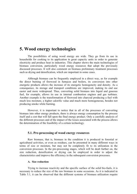
<strong>5.</strong> <strong>Wood</strong> <strong>energy</strong> <strong>technologies</strong><br />
The possibilities of using wood <strong>energy</strong> are wide. They go from its use in<br />
households for cooking to its application in great capacity units in order to generate<br />
electricity and produce heat in industries. This chapter shows the main <strong>technologies</strong> of<br />
biomass conversion, particularly wood <strong>energy</strong> resources that adopt the previously<br />
discussed processes. It will also comment on biomass preliminary treatment processes<br />
such as drying and densification, which are important in some cases.<br />
Although biomass can be frequently employed in a direct way, as for example<br />
the direct burning of firewood in furnaces and boilers, its conversion into other<br />
energetic products allows the increase of its energetic homogeneity and density. As a<br />
consequence, its storage and transport conditions are improved, making its end use<br />
easier and more widespread. Thus, converting solid biomass into liquid and gaseous<br />
fuel, for example, allows its use in internal combustion engines and gas turbines.<br />
Another example is the transformation of firewood into charcoal producing a fuel with<br />
much less moisture, a higher calorific value and much more homogeneous, besides not<br />
producing smoke while burning.<br />
However, it is important to notice that in all of the processes of converting<br />
biomass into other <strong>energy</strong> products, there is always <strong>energy</strong> consumption by the process<br />
itself and a cost that will fall upon the final <strong>energy</strong> product. Only a carefully analysis of<br />
the different processes and of the impact of the losses associated with the process allows<br />
the determination of the feasibility of a certain technology.<br />
<strong>5.</strong>1. Pre-processing of wood <strong>energy</strong> resources<br />
Raw biomass, that is, biomass in the condition it is produced in forestial or<br />
agricultural activities, or even as residues, can be presented in many different ways in<br />
terms of size or moisture, but may not be completely fit to its utilization in the<br />
conversion processes. In the pre-processing stages, which will be dealt further on, the<br />
size reduction, densification or drying can be employed in order to adjust the<br />
characteristics and improve the efficiency in the subsequent conversion processes.<br />
A. Size reduction<br />
Trying to increase reactivity and the specific surface of the solid bio-fuels, it is<br />
necessary to reduce the size of the raw biomass in some occasions. As it is indicated in<br />
Table <strong>5.</strong>1, it can be observed that the different systems of biomass utilization require
well-defined particle sizes in order to achieve good operating conditions and high<br />
efficiency. For example, moving bed gasifiers are more efficient when operating with<br />
biomass in pieces of 5-10 cm. This way, it is necessary to cut the wood in pieces within<br />
these dimensions, or in case of a fine-sized biomass residue the pieces should be fitted<br />
to 5 – 10 cm by means of briquetting. For those systems where biomass has a short<br />
residence time within the reaction zone, a fine-sized biomass makes them more<br />
efficient. In this case, different types of mills are used for pulverization. Figure <strong>5.</strong>1<br />
shows the most widespread types of wood shredders.<br />
Table <strong>5.</strong>1 – Biomass recommended particles/sizes for different applications.<br />
Type of biomass utilization system Recommended size, mm<br />
Moving bed. 50-100<br />
Suspension burning < 6.0-7.0<br />
Bubbling fluidized bed 20-30<br />
Circulating fluidized bed < 6.0-7.0<br />
B. Drying<br />
Some types of biomass present very high moisture making their use as fuel<br />
difficult and, therefore, reducing the amount of available <strong>energy</strong> to be converted into<br />
heat. Within the combustion processes, the evaporated moisture consumes part of the<br />
released <strong>energy</strong>, the one that is, technically, hard to recover. Besides, it makes the fuel<br />
ignition difficult and reduces the combustion temperature. Thus, most of the combustion<br />
systems require a fuel with moisture lower than 50-60% (wet basis). Considering the<br />
calorific value increasing with moisture reduction, the less the moisture, the less<br />
biomass is needed.<br />
In relation to gasifiers, moisture remarkably affects the composition and the<br />
calorific value of the attained gas, so the recommended moisture ranges between 15% to<br />
20%. Recently cut firewood as well as sugar cane bagasse at the mill outlet present<br />
approximately 50% of moisture in wet basis, a level considered to be high for an<br />
efficient use. This way, a preliminary drying is necessary in order to fit the biomass<br />
moisture for a certain conversion process.<br />
The two main factors that limit the drying rate are: the transfer of biomass<br />
moisture into the air and the diffusion or migration of the moisture inside the biomass<br />
volume. The biomass drying can be carried out in a natural way or by using dryers.<br />
Through the natural drying process it is possible to achieve a final moisture ranging<br />
between 15% to 20% in wet basis within a period of two or three months when the<br />
biomass is stored under good conditions of air circulation and climate.<br />
62
Figure <strong>5.</strong>1 – <strong>Wood</strong> shredders<br />
The dryers allow this time to be significantly reduced, even during rainy and wet<br />
periods. The most common drying agents used in dryers are the biomass combustion<br />
products from the burning in boiler furnaces, which are released into the atmosphere at<br />
temperatures ranging between 150 o to 300 o C. In the last few years, drying with<br />
63
superheated steam has been highly widespread. The most commonly employed dryers<br />
and their features will be dealt next.<br />
Rotary dryer: This dryer, shown in Figure <strong>5.</strong>2, is known by the sugar industry as<br />
Rader-Thompson and it can be employed for a wide scope of biomass types and sizes.<br />
The dryer itself is a drum with blades throughout its internal perimeter that allow the<br />
residence period of the material inside the dryer to be enhanced. The final moisture that<br />
rotary dryers can achieve operating with sugar cane bagasse is approximately 35%.<br />
There are three of these dryers installed in Hawaii. Their average electric <strong>energy</strong><br />
consumption is 13.5 kWh/t of bagasse to dry (KINOSHITA, 1989). According to the<br />
same author, a 0.14% reduction of CO concentration in the combustion products was<br />
observed, and this is equivalent to an increase of 0.7% in the boiler efficiency. The<br />
efficiency of the steam generators increases about 5% when the dryer is in operation.<br />
Figure <strong>5.</strong>2 – Rotary dryer for biomass.<br />
Figure <strong>5.</strong>3 – Pneumatic dryer for bagasse<br />
64
Pneumatic dryer: In this equipment, the biomass drying takes place basically during its<br />
movement through pneumatic transport in the dryer vertical duct as it is shown in Figure<br />
<strong>5.</strong>3. The COPERSUCAR Technology Center in Brazil developed a pneumatic dryer for<br />
sugar cane bagasse with a capacity of 20 t/h. It can reduce the bagasse moisture from<br />
50% to 23% (CAMPANARI, 1984). As a disadvantage, its design and operation<br />
efficiency greatly depend on the biomass particle size. Studies carried out by NEBRA<br />
and MACEDO (1989) detected that an important fraction of the moisture reduction<br />
takes place in the separating cyclone.<br />
Mixed bed dryer: This type of dryer, presented by FORSS and MUONIOVARA<br />
(1996), is coupled to fluidized bed combustors. It uses the heat directly from itself for<br />
the drying, and that takes place in steam atmosphere. This way it is possible to recover<br />
the latent heat for the process at a reasonable thermal level. The increase in the<br />
efficiency of the plant is 15% and it is determined based on the LCV. Figure <strong>5.</strong>4 shows<br />
the operating principle of a mixed bed dryer.<br />
C. Densification<br />
Figure <strong>5.</strong>4 – Scheme of a mixed bed dryer.<br />
The low density of some types of biomass, particularly agricultural and agroindustrial<br />
residues such as sawdust and wood shaves, rice husks and sugar cane bagasse,<br />
makes their long distance transport and storage difficult, therefore economically<br />
unfeasible. In order to improve this situation, a lot of work has been done within the last<br />
few years in order to develop different densification <strong>technologies</strong>.<br />
The elements of densified biomass are named pellets or briquettes, and their<br />
predominant particle size ranges between 10 and 30 mm with a density that can reach<br />
from up to 1,100 to 1,300 kg/m3. Typically, the products attained through selfagglomeration<br />
by means of a combined action of heat and pressure are called pellets,<br />
whereas briquettes are the densification products that require biding agents such as<br />
charcoal. The most common densification systems are shown in Figure <strong>5.</strong><strong>5.</strong> They can be<br />
presses with mechanical or hydraulic driving or with disc or annular-shaped matrices, or<br />
even, extruding ones (or screw systems).<br />
65
Figure <strong>5.</strong>5 – Equipment for biomass densification.<br />
The <strong>energy</strong> demand that is necessary to achieve a suitable density has important<br />
influence regarding the densification systems of some sorts of residues. REED et al.<br />
(1980) pointed out that the amount of <strong>energy</strong> necessary for the densification could be<br />
reduced in approximately twice if the biomass was previously heated at a temperature<br />
ranging between 100 and 230°C. In addition, such fact leads to a certain increase in the<br />
pellets calorific value because of the release of part of the volatiles with low calorific<br />
value.<br />
The <strong>energy</strong> consumption of a wheat straw densification installation with annular<br />
matrix press ranges typically from 37 to 64 kWh/t. However, considering all the <strong>energy</strong><br />
consumed during the harvest, the size reduction and particle size classification, the<br />
number mentioned above grows from up to 90 to 120 kWh/t. (THOMAS, 1980).<br />
Results of researches about sugar cane bagasse densification can be found in<br />
McARTHUR (1981) and SILVA (1988). GREVER and MISHA (1994) compared the<br />
piston presses with the extruding ones during the production of briquettes out of wood<br />
residues, and the main results are displayed in Table <strong>5.</strong>2. Their conclusions indicate that<br />
the extruding presses are more appropriate for developing countries. Matrix presses are<br />
frequently used for sugar cane bagasse for they are more economical regarding this<br />
matter.<br />
66
Table <strong>5.</strong>2 – Comparison between piston and extrusion presses<br />
Parameter or characteristic Piston press Extruding press<br />
Matter optimum moisture 10-15% 8-9%<br />
Briquette density 1,000-1,200 kg/m3 1,000-1,400 kg/m3<br />
Power consumption 50 kWh/t 60 kWh/t<br />
Maintenance high low<br />
Use in gasifiers not recommendable recommendable<br />
<strong>5.</strong>2. Biomass direct combustion<br />
The burning of biomass, mainly firewood, is the most widespread wood <strong>energy</strong><br />
technology and it presents several systems according to the application context. Initially<br />
the aspects associated with household use will be presented, afterwards the industrial<br />
systems will be considered.<br />
A. Residential systems<br />
Millions of people throughout the world depend on biomass as the only possible<br />
<strong>energy</strong> source for daily cooking. It is estimated that 75% of the biomass used in<br />
developing countries have this purpose. In general, the systems employed for biomass<br />
burning are extremely simple and they don’t allow the appropriate use of the thermal<br />
<strong>energy</strong> generated by the combustion, besides they produce a lot of smoke, consequently,<br />
they are hazardous for the users’ health. Figure <strong>5.</strong>6 shows a classification of biomass<br />
stoves, specially taking the employed fuel into account. The schemes corresponding to<br />
these types of stove are presented in Figure <strong>5.</strong>7.<br />
Figure <strong>5.</strong>6 – Biomass stove classification.<br />
(The letters in parentheses indicate the corresponding scheme in Figure <strong>5.</strong>7)<br />
67
Driven by the possibilities of improving life conditions and reducing bio-fuels<br />
consumption, above all in regions where they are scarce, over the last 20 years several<br />
institutions have been working on the development of efficient models of stoves that use<br />
firewood and other sorts of biomass in order to accomplish a more reasonable use of<br />
this fuel. It is considered that an appropriate stove for biomass must be able to meet the<br />
following conditions:<br />
• High efficiency in combustion and heat transfer to the pans.<br />
• Sufficient thermal power (According to MUKUNDA (1993), at least 4 KW for one<br />
hour and a half).<br />
• Low cost and high durability.<br />
• Low pollutant emission into the environment (CO and tar).<br />
• Acceptance among the users.<br />
• Easy manufacturing and repairing (using local material).<br />
• Safe use (low risk of fires and burns).<br />
• Easy fire setting.<br />
• Not making the saucepans dirty on the outside.<br />
a) Three stone stove.<br />
b) “Heavy” stove with chimney.<br />
c) “Light” stove with chimney<br />
(Nepal).<br />
d) No chimney stove for one pan<br />
(Thailand).<br />
e) No chimney stove for two saucepans<br />
(Indonesia).<br />
f) Charcoal metal stove (“Jiko” type).<br />
g) Charcoal pottery stove<br />
h) Sawdust and rice husk compact stove<br />
Figure <strong>5.</strong>7 – Different types of biomass stoves scheme<br />
68
The presence of a chimney is relevant to reduce the impacts associated with the<br />
smoke emissions and it can also help to control the air excess, which directly affects<br />
efficiency. Suitable culinary practices such as washing vegetables before cooking and<br />
the use of lids, as well as using dry firewood protecting it from inclemency, are<br />
measures that are as important as the stove design.<br />
Programs introducing improved and low cost stoves, such as the Lorena stove<br />
(built with clay and sand) from Guatemala, were introduced in practically every<br />
continent showing distinct degrees of success. In technical literature there is a great<br />
amount of information regarding the development and diffusion activities of traditional<br />
and improved <strong>technologies</strong> for cooking with firewood or charcoal. So, it is evident that<br />
it is always important to respect the values and interests of the consumers, giving<br />
special consideration to the role of women.<br />
In order to determine the efficiency of biomass stoves, the method that is usually<br />
accepted is the boiling water test. In this case, the efficiency is calculated as the relation<br />
between the amount of heat absorbed by the water in the cooking pans and the amount<br />
of heat supplied by the fuel. The equation for the calculation is:<br />
Where:<br />
M H O . C.( Te− Ti) + Mevap . L<br />
2<br />
η=<br />
. 100 % (<strong>5.</strong>1)<br />
t<br />
M . PCI<br />
comb<br />
M - Mass of water in the pan at the beginning of the experiment, kg<br />
HO<br />
2<br />
C - Water specific heat, kJ/kg o C<br />
Te - Boiling temperature, corresponding to the atmospheric pressure at the<br />
place where the stove will be used, o C<br />
Ti - Water temperature at the beginning of the experiment, o C<br />
M - Mass of evaporated water, kg<br />
evap<br />
L - Water vaporization heat, for the local utilization conditions of the stove,<br />
kJ<br />
M comb. – Mass of burned fuel, kg<br />
LCV t - Fuel low calorific value, kJ/kg<br />
Table <strong>5.</strong>3 shows the efficiencies, which are mentioned in the literature, for<br />
different types of firewood stoves. They were attained by using the boiling water test.<br />
The efficiencies of gas and electrical commercial stoves are used with comparison<br />
purposes.<br />
The estimative of firewood demand within the household sector is almost always<br />
carried out based in surveys and field evaluations, and it can vary significantly from one<br />
region to another, above all due to the fuel availability. The average value of firewood<br />
annual demand is about 1 m 3 per person. In order to help the survey, it is often<br />
necessary to know the load units of firewood for household consumption, and the<br />
number of people necessary for their transport, as shown in Table <strong>5.</strong>4. These data were<br />
evaluated within Brazilian conditions.<br />
69
Table <strong>5.</strong>3 - Efficiencies recorded in different types of firewood stoves and commercial<br />
kitchens.<br />
Type of stove Efficiency References<br />
“Three stone” stove 10-7<br />
10-15<br />
BHATT (1983)<br />
WEREKO-BROBBY e HAGEN<br />
(1996)<br />
“Heavystove” stove with<br />
chimney<br />
15-23 CLAUS e SULILATU (1983)<br />
No chimney stove for one pan 30 DUNN et. alli (1983)<br />
35 WEREKO-BROBBY e HAGEN<br />
(1996)<br />
No chimney stove for two pans 18-22 CLAUS e SULILATU (1983)<br />
Compact stove for sawdust and 15* MUKUNDA et alli (1993)<br />
rice husks<br />
32-36**<br />
Gas stove 57 WEREKO-BROBBY e HAGEN<br />
(1996)<br />
Electrical stove 50 WEREKO-BROBBY e HAGEN<br />
(1996)<br />
* Traditional model, ** Improved model<br />
Table <strong>5.</strong>4 – Firewood typical loads for household use<br />
Person that carries firewood typical load, kg<br />
Boys (8-10 years old)<br />
7<br />
Teenagers – male (12-15 years old)<br />
15<br />
Adult women<br />
23<br />
Teenagers – female<br />
33<br />
Men<br />
35<br />
Another way of using wood <strong>energy</strong> within the household scenario, which is not<br />
as important as the preparation of food, is in heating kilns. Furnaces are basically used<br />
for that purpose, and over the last few years they have shown remarkable development.<br />
In some industrialized countries, such as Canada and France, firewood has become a<br />
source of heat throughout cold periods, where, most of the time, it is consumed in<br />
automized and highly efficient systems. Some countries in Europe, as for example<br />
Denmark, Sweeden and Finland have been using firewood biomass and agricultural<br />
residues for heating in distrital central heating systems where the heat is produced in a<br />
central boiler and it is distributed to the houses as hot water and low pressure steam.<br />
B. Industrial systems (Process heat generation)<br />
Direct biomass combustion is widely used to generate heat in several industrial<br />
processes using kilns or boilers. In the first case, kilns require high temperatures, in<br />
general over 500 o C, as for example, the manufacturing of pottery products where the<br />
heat produced by the combustion must be transferred directly to the material being<br />
processed. On the other hand, the objective of the boilers is the steam production, which<br />
is used as a thermal <strong>energy</strong> source in the industrial process or also, used for the<br />
70
production of mechanical or electrical power by means of steam turbines. The turbine<br />
exhaust steam can also be used for heat supply, which is known as cogeneration.<br />
The industrial processes need steams at relatively low pressure levels,<br />
approximately ranging from 0.2 to 0.4 MPa. However, considering that the elevation of<br />
the steam parameters (pressure and temperature) allows the efficiency to increase during<br />
electricity generation in a cogeneration cycle, it is common to produce steam at<br />
pressures that range between 7 and 14 Mpa and temperatures between 500 and 550 o in<br />
modern boilers.<br />
There are many examples of industrial systems that depend on biomass direct<br />
thermal <strong>energy</strong>. In plants that produce cellulose pulp and in sugar mills the main fuels<br />
are by-products and lignocellulosic residues such as bagasse, black liquor and cork.<br />
Biomass is also the essential <strong>energy</strong> source in several types of small and medium-sized<br />
agro-industries that process and treat agricultural and cattle products. This way, its<br />
thermal applications are commonly used for coffee and rice processing are common<br />
where, besides firewood, their own by-products (coffee pods and rice husks) constitute,<br />
most of the time, the fuel used to obtain hot air for the drying and the generation of<br />
electricity required for the treatment process of the grains.<br />
The brick and tile industry is another example of biomass consuming industry,<br />
mainly firewood, which is used in kilns to burn bricks and tiles. In Brazil, orange juice<br />
industries located in sugar cane areas consume a considerable amount of sugar cane<br />
bagasse for fuel. Another interesting case that can be mentioned is the extensive use of<br />
spent coffee grounds in soluble coffee industries because of the high moisture of this<br />
biomass residue. This topic presents the types of equipment and the basic methodology<br />
employed for their evaluation.<br />
B.1. Grates and combustion systems<br />
In order to make use of an efficient combustion, i. e., a complete burn of<br />
biomass using the least amount of air possible, several systems can be employed. There<br />
are two basic types: biomass bed (or piles) or suspension burning. While the first is<br />
simpler, the suspension systems require small-sized biomass allowing the operation<br />
with less air excess, thus they are more suitable for high capacity equipment. Figure <strong>5.</strong>8<br />
presents schemes of the different types of combustion systems used for biomass burning<br />
of which technical characteristics are shown in Table <strong>5.</strong>5 according to MITRE (1982),<br />
PERA (1990), BAZZO (1992), SILVA (1995), TOPLEY (1992), HUGOT (1986) and<br />
LEPPA (1982).<br />
The most important parameters to define the furnace maximum capacity during<br />
the burn of a certain fuel are the volumetric thermal load (Qv) and the grate surface<br />
thermal load (Qf). These parameters define the amount of heat that is released by each<br />
furnace volume unit or by the grate surface, respectively. Naturally, the high values of<br />
these parameters indicate more compact systems that, at fist, are less expensive. On the<br />
other hand, in order to make use of a suitable mixture of air and fuel, it is necessary to<br />
use of air circulating systems with forced and induced draught, that in turn requires fans<br />
and control and driving systems, consequently increasing their complexity.<br />
71
Table <strong>5.</strong>5 – Technical characteristics of the furnaces used for biomass combustion.<br />
Combustion system Qf<br />
kW/m 2<br />
Qv<br />
kW/m 3<br />
Boiler<br />
maximum<br />
capacity<br />
72<br />
Biomass<br />
moisture<br />
t/h %<br />
Cellular furnaces. 3.9 - 45 100 30-50<br />
Suspension burning furnaces. 2.6-3.7 < 0.41 180-550 < 15<br />
Figure <strong>5.</strong>8 – Combustion systems used for biomass.<br />
The combustion systems with cellular furnaces are being progressively set aside, above<br />
all because of their low efficiency, which is a consequence of the high excess of air that<br />
they need. In medium-capacity applications, inclined grate furnaces with inclinations<br />
between 37 and 55 o C seem to be more interesting, for they allow the use of pre-heated<br />
air at temperature levels that are superior to 300 o C, which helps to improve the<br />
combustion conditions significantly. Suspension combustion systems are adopted at<br />
elevated capacities and whenever the biomass is available in particles whose sizes are<br />
smaller than 10 mm, which is the case of bagasse and sawdust<br />
B.2. Boilers<br />
Boilers or steam generators may have two basic types: of fire or water tubes. In<br />
the first group, which is also known as fire tube boilers, the combustion products<br />
circulate inside the tubes and transfer their thermal <strong>energy</strong> to the water that surrounds<br />
them. This type of boiler is high employed, although it presents limits in terms of<br />
production capacity that reaches approximately 20 t/h and steam maximum pressure of<br />
2.0 MPa. It is mainly applied in small and medium agro-industries that nearly always<br />
demand saturated steam with a pressure lower than 0.4 MPa for heating purposes.<br />
Figure <strong>5.</strong>9 – Fire tube boiler for biomass.<br />
In watertube boilers, the water that will be vaporized circulates in the interior of<br />
the tubes that receive heat from the gases resulting from biomass combustion from the<br />
outside. Through this design it is possible to attain great volumes of steam, even<br />
superheated and high-pressure ones. Watertube boilers are adopted whenever the steam<br />
pressure to be produced surpasses 2 MPa and the steam capacity is greater than 20 t/h.<br />
Owing to the development of the technology of constructing boilers, today, there are<br />
different types of boilers for biomass, which are displayed in Figure <strong>5.</strong>10. The two drum<br />
73
convective boilers and the radiant boilers correspond to the modern technology of heat<br />
generation with high capacity and efficiency. Table <strong>5.</strong>6 indicates the most significant<br />
characteristics of watertube boilers.<br />
Figure <strong>5.</strong>10 – Basic constructive types of biomass firetube boilers.<br />
Table <strong>5.</strong>6 – Most important data and parameters of the different types of biomass<br />
boilers.<br />
Data and parameters Straight<br />
tubes<br />
Typically adopted<br />
furnace<br />
Efficiency (related to the<br />
LCV), %<br />
cellular<br />
furnace or<br />
inclined<br />
grate<br />
Types of boiler<br />
Curved<br />
tubes with<br />
several<br />
drums<br />
moving<br />
grate<br />
Convective<br />
with two<br />
drums<br />
moving<br />
grate<br />
Radiant<br />
suspension<br />
or fluidized<br />
bed<br />
50-60 50-70 70-80 80-87<br />
Steam temperature, o C 300 320 320-510 400-550<br />
Steam pressure, MPa 1.8 1.8-3.0 1.8-14.0 7.0-13.0<br />
Steam maximum<br />
generation, t/h<br />
35 60 80 até 550<br />
Figure <strong>5.</strong>11 shows a scheme of a modern watertube boiler for biomass burning.<br />
According to the numbering used in this figure, its main parts and functions are:<br />
74
1. Furnace: it is the space or volume where the total combustion of the gases<br />
resulting from the pyrolysis of the biomass on the grate takes place. In<br />
burning in suspension systems, the burning of the solid fuel occurs in all its<br />
own volume.<br />
2. Grate: it is the element that supports the combustion matter at the same time<br />
that distributes the primary air. This device also guarantees the periodic<br />
removal of the accumulated ash on the grate.<br />
3. Biomass feeders: Their function is to feed the fuel that will be burnt in the<br />
furnace distributing it in homogenous layers on the grate. They may be<br />
mechanical or pneumatic.<br />
4. Water walls: they are evaporative surfaces that cover the walls of the furnace<br />
partially or completely. It is formed by tubes where the water circulates<br />
throughout the evaporating process.<br />
<strong>5.</strong> Convective bank: It is a group of tubes connected to the superior and inferior<br />
drums. It is also an evaporative surface that receives the heat of the gases due<br />
to the convection.<br />
6. Superior drum: it receives the water-steam mixture that comes from the<br />
evaporative surfaces carrying out the separation of the saturated steam from<br />
the water supply to the evaporative surfaces through downcorner feeding<br />
tubes.<br />
7. Inferior drum: It works as a collector-distributor of water during the<br />
evaporation.<br />
8. Superheater: It allows the conversion of saturated steam into superheated<br />
steam with a reduced loss of pressure. It has devices to control the steam<br />
temperature called atemperators.<br />
9. Air pre-heater: It is a surface where the pre-heating of air, which will be<br />
introduced in the furnace together with the biomass, takes place. It uses<br />
residual thermal <strong>energy</strong> that is available in the combustion products.<br />
10.Economizer: It is a heat exchanger. It pre-heats the feeding water using the<br />
combustion gases until saturation temperature.<br />
Figure <strong>5.</strong>11 – Biomass steam boiler scheme.<br />
75
The economizer and the air pre-heater are components that don’t necessarily<br />
exist in every boiler. However they are interesting, for they allow the recovery of part of<br />
the thermal <strong>energy</strong> available in the gases that will go to the stack, therefore reducing<br />
losses and increasing efficiency.<br />
Figure <strong>5.</strong>12 shows the scheme of a modern biomass steam boiler of 210 t/h<br />
steam capacity and steam parameters 6.6 MPa and 520 o C. (APU-70-76I-PSE type<br />
boiler manufactured by Caldema Equipamentos Industriais Ltda). It is a suspended or<br />
hanging boiler with seven section pinhole type grate. It has primary and secondary<br />
superheaters, one pass in the convective bank, primary and secundary air pre-heater, and<br />
finned economizer. Superheated steam temperature control is carried out by using a<br />
ventury attemperator located in the intermediate collector between primary and<br />
secundary superheaters. Water used for temperature control comes from a tube-shield<br />
condenser, that condenses the steam from the drum. The reason to use a condenser is<br />
that the water, obtained by steam condensation, injected in the Venturi, has the same<br />
quality as the superheated steam to be attemperated. The fact that this boiler is being<br />
used for cogeneration makes the occurrence of salts deposition on the steam turbine<br />
blades possible, so a high quality of superheater steam is required<br />
Figure <strong>5.</strong>12 – Industrial steam boiler for sugar cane bagasse burning (courtesy<br />
of Caldema Equipamentos Industriais Ltda).<br />
A very important operational aspect regarding steam generation is the quality of<br />
the water. It must have a low content of salts, for after the water evaporation these<br />
products will be deposed in the surfaces of thermal exchange and they cause highly<br />
risky situations. This way the water must be treated before being fed to the boiler<br />
through the addition of chemical products, and periodical extractions of the liquid<br />
volume present in the boiler superior drum must be carried out. The most frequently<br />
used chemical products are phosphates and hidrazine.<br />
76
In the last 25 years, fluidized bed boilers appeared in the market. Their<br />
advantage in relation to conventional <strong>technologies</strong> allowed to enhance significatilly the<br />
utilization of different kind of biomass residues for electricity generation and<br />
cogeneration. A common aspect in all the fluidized bed boilers is the combustion of the<br />
fuel in an inert material particulate volume (sand), that guarantees an intensive heat<br />
transfer, allowing the combustion to happen at a relatively low temperature level (800-<br />
900 o C).<br />
There are two types of fluidized bed boilers:<br />
- With a bubbling fluidized bed - BFB (Figure <strong>5.</strong>13). The inert bed (sand) expands, but<br />
keeping a defined height. Fluidization velocity (air velocity in the free furnace cross<br />
section) is 1-3 m/s;<br />
- With a circulating fluidized bed - CFB (Figure <strong>5.</strong>14). The inert material and the fuel<br />
circulate through the bed, a separating cyclone and finally returns to lower part of the<br />
bed. Combustion is finished in a few circulating cycles, making the residence time and<br />
combustion efficiency to be high. The fluidization velocity in these systems is higher,<br />
attaining 4-12 m/s. CFB units reach a capacity up to 250 MW.<br />
Figure <strong>5.</strong>13 – Bubbling fluidized bed boiler for biomass.<br />
Figure <strong>5.</strong>14 – Circulating fluidized bed boiler for biomass.<br />
77
Fluidized bed boilers have the following advantages (VTT, 2001):<br />
- Combustion stability, even with considerable variation in size distribution, moisture<br />
content, ash content and fuel calorific value;<br />
- Possibility of using fuels with low volatiles and high ash content;<br />
- Possibility burning different fuels simultaneously;<br />
- Possibility of an efficient control of SOx and NOx emissions, not requiring high cost<br />
control equipment.<br />
B.3. Boiler efficiency<br />
A very important parameter to indicate the perfection degree in an <strong>energy</strong><br />
conversion process, such as the one that occurs in a steam generator, is the efficiency,<br />
which is shown in this topic. If one considers that the total <strong>energy</strong> and mass involved in<br />
the combustion and heat transferring processes, the determination of the efficiency in<br />
the conversion of the chemical <strong>energy</strong> available in the fuels into steam potential <strong>energy</strong><br />
will be essentially based on the evaluation of mass and <strong>energy</strong> flows that can be found<br />
in steam generators as it is shown afterwards.<br />
Figure <strong>5.</strong>15 shows the mass balance of a steam generator where:<br />
mvs - steam production, kg/s<br />
La - air flow for the combustion, kg/s<br />
C - fuel consumption, kg/s<br />
∆L1, ∆L2 e ∆L3 – air infiltration in the boiler, kg/s<br />
Gcen1 - ashes removed through the grate, kg/s<br />
Gcen2 - ashes removed through the convective bank hoppers, kg/s<br />
Gcen3 - ashes dragged with the gases, kg/s<br />
Daa - feeding water flow, kg/s<br />
Dext - drum extraction (purge) flow, kg/s<br />
- exhaust gas flow, kg/s<br />
Lg<br />
By using these variables, the mass balance for the fuel and gases, as well as for<br />
water and steam can be directly written. In the same way, once the fuel ash content is<br />
known, A t , the balance regarding these inert materials can also be implemented in terms<br />
of combustion. In this present analysis, the ashes were considered to leave the boiler<br />
from three points: the grate ashtray, the hoppers of the gas vertical conduct and as<br />
volatile ashes dragged together with the gases.<br />
78
Fuel and gas balance.<br />
3<br />
Figure <strong>5.</strong>15 – Mass balance in a steam generator.<br />
∑ ∑<br />
L + C+ ∆L<br />
= L + Gcen<br />
a i g<br />
i = 1<br />
i = 1<br />
Water and steam balance.<br />
Ash balance.<br />
Daa = mv+ Dext<br />
.<br />
t<br />
A C = Gcen + Gcen + Gcen<br />
1 2 3<br />
3<br />
i<br />
79<br />
(<strong>5.</strong>2)<br />
(<strong>5.</strong>3)<br />
(<strong>5.</strong>4)<br />
In order to carry out the <strong>energy</strong> balance in a steam boiler the fuel high or low<br />
calorific value can be considered as the available <strong>energy</strong>. Actually, both of the<br />
parameters are employed. However, it is important to remember that the water present<br />
in the combustion products remains as steam for low calorific values, which is a typical<br />
condition in the gases of a real boiler. This is the reason why, in the scheme of Figure<br />
<strong>5.</strong>16 where the thermal <strong>energy</strong> flows in a boiler and in the subsequent balances are<br />
shown, the LCV t is employed. The variables in this case, expressed in kJ/kg of fuel or<br />
power units are:<br />
t<br />
Q d<br />
Qev<br />
Qca<br />
- <strong>energy</strong> that enters the boiler control volume, known as “available<br />
heat”, and corresponds to the fuel low calorific value<br />
- <strong>energy</strong> absorbed in the evaporative surfaces<br />
- <strong>energy</strong> absorbed in the air pre-heater
Qec<br />
Qsa<br />
Qp2<br />
Qp3<br />
Qp4<br />
Qp5<br />
Qp6<br />
Hge<br />
- Energy absorbed in the economizer<br />
- Energy absorbed in the superheater;<br />
- Stack gas heat losses;<br />
- heat losses caused by incomplete combustion due to combustible<br />
gases (CO, H2 and CH4) presence in the combustion products.<br />
In technical literature, they are named heat losses because of<br />
incomplete chemical combustion;<br />
- heat losses caused by incomplete combustion due to carbon and soot<br />
presence in the ashes. The literature calls them heat losses caused by<br />
incomplete “mechanical” combustion (This is related to the fact that<br />
this losses are a consequence of a “mechanical” or physical process of<br />
fuel particles carry-over);<br />
- heat losses to the surroundings removal of ashes through the boiler<br />
walls;<br />
- heat losses due to high temperature removal of ashes;<br />
- exhaust gases enthalpy.<br />
The fraction of available heat that is used or “useful heat” transferred to the<br />
steam may be defined as the difference between the available heat in the fuel and the<br />
several losses, that is:<br />
6<br />
t<br />
Qutil<br />
= Qec<br />
+ Qev<br />
+ Qsc<br />
= C.<br />
PCI −∑<br />
Qpi<br />
i=<br />
2<br />
Table <strong>5.</strong>7 – Heat losses in boilers<br />
Losses Value approximate<br />
range, %<br />
Comments<br />
80<br />
(<strong>5.</strong>5)<br />
Qp2 8 - 18 For a temperature of exhaust gases<br />
from 180 to 200 o C, Qp2 ≈ 12% of the<br />
LCV t .<br />
Qp3 (as fuel gases) 0.5 – 1.5 At normal conditions, the fraction of<br />
fuel gases represents about 0.5% of the<br />
LCV t<br />
Qp4 (as carbon in the<br />
ashes and soot)<br />
1 - 4 This loss depends directly on the<br />
combustion system and fuel size<br />
Qp5 0.8 – 4.5 In boilers that are correctly designed<br />
and operated, this less is about 2% of<br />
the fuel <strong>energy</strong><br />
Qp6 < 0.1 It can be neglected.
Observe that Qca was not included as useful heat, for it constitutes an internal<br />
transference in the control volume, that is, the <strong>energy</strong> that is recovered from the exhaust<br />
gases in the air preheater is reintroduced in the furnace as hot air. Table <strong>5.</strong>7 presents the<br />
indicative values of heat losses in real boilers. Considering extreme situations, the<br />
efficiency of well-designed and well-operated steam generators usually ranges between<br />
65 and 85% for small-sized systems with great generation capacity, respectively.<br />
Naturally, the previous expressions could be more detailed or could be presented related<br />
to other parameters. Figure <strong>5.</strong>16 shows a diagram of <strong>energy</strong> flows entering and exiting<br />
the control volume of a steam generator.<br />
Figure <strong>5.</strong>16 – Energy balance in a boiler.<br />
Once the mass and <strong>energy</strong> balance are known, the relations to determine the<br />
efficiency can be shown, that is, the fraction of biomass heat in the produced steam.<br />
Since the sum of the used heat and the losses always equals the heat supplied by the<br />
burning of the fuel, it is possible to calculate the efficiency through two different ways:<br />
evaluating the useful effect or the heat corresponding to the steam (direct balance) or<br />
measuring<br />
or estimating the losses that subtracted from the heat supplied by the biomass<br />
equals the useful heat (indirect<br />
balance):<br />
Direct balance:<br />
Q<br />
=<br />
CPCI .<br />
util<br />
ηc t<br />
Indirect balance:<br />
η<br />
=<br />
C.<br />
PCI<br />
t<br />
−<br />
6<br />
∑<br />
Qp<br />
i<br />
6<br />
∑<br />
Qp<br />
i<br />
∑<br />
i = 2<br />
i=<br />
2 = 1 − = 1 − specific losses<br />
t<br />
C.<br />
PCI<br />
C<br />
81<br />
(<strong>5.</strong>6)<br />
c (<strong>5.</strong>7)
The indirect method is the most used one, for it allows the efficiency to be<br />
determined without necessarily impose fuel and steam flow measurements, which are<br />
specially complicated in the case of small and medium-sized systems. In general, the<br />
most important losses take place because of the residual <strong>energy</strong> of the exhaust gases,<br />
and they are evaluated by measuring the temperature of the gases and the air excess that<br />
most of the time, is measured by using gas analyzers (determining the gas composition).<br />
<strong>5.</strong>3.<br />
Applied gasification<br />
This topic presents the basic aspects of the conception and operation of gasifiers<br />
that allow the conversion of solid biomass into gas fuel. The biomass gasifier is an<br />
equipment that present a great technological diversity<br />
and they can be classified in<br />
several<br />
ways according to the following parameters:<br />
Produced gas calorific value:<br />
Gas of high calorific value - from 10 to 40 MJ/Nm 3 • Gas of low calorific value – up to 5 MJ/Nm<br />
.<br />
3 .<br />
• Gas of medium calorific value - from 5 to 10 MJ/Nm<br />
•<br />
It must be observed that Nm<br />
nce conditions (normal conditions), that is, 1 atmosphere of pressure and<br />
0ºC.<br />
3 is understood to be the gas volume measured at<br />
refere<br />
Type of gasification agent:<br />
• Air.<br />
• Water steam.<br />
• Oxygen.<br />
Working pressure:<br />
• Low pressure (atmospheric) .<br />
• Pressurized (up to 3 MPa).<br />
Direction of the biomass relative movement and of the gasification agent:<br />
• Bed moving in the opposite direction of the gas flow (counter current<br />
or up-draft).<br />
• Bed moving in the same direction as the gas flow (down-draft).<br />
• Bed moving perpendicularly<br />
to the gas flow (cross-draft).<br />
• Fluidized bed.<br />
The calorific value of the attained gas greatly depends on the type of gasification<br />
agent and the operation pressure as it is indicated in Table <strong>5.</strong>8, which, also shows the<br />
possible applications of the produced gas. The gasification employing air is the most<br />
widespread and allows the production of a lower cost gas. However, in this alternative,<br />
the gas presents a low calorific value. When the gasification gas constitutes the raw<br />
material for the production of liquid derived from biomass, steam or oxygen must be<br />
3 .<br />
82
employed as gasification agents. Another factor that affects the gas calorific value is the<br />
biomass moisture, which is recommended to be lower than 20%.<br />
Among the gasifier classification criteria presented<br />
above, the most adopted is<br />
the<br />
direction of biomass movement and the gasification agent relative movement. Figure<br />
<strong>5.</strong>17 displays the schemes of basic types of gasifiers.<br />
Figure <strong>5.</strong>17 – Types of biomass gasifiers.<br />
Table <strong>5.</strong>8 – Dependence among the type of gasification agent employed, the gasifier<br />
pressure, the gas calorific value<br />
and its possible application.<br />
Gasification agent air steam oxygen<br />
Operation pressure Atmospheric Atmospheric Pressurized Gas calorific value<br />
3<br />
(MJ/Nm )<br />
4 – 6 10 - 18 18 - 14<br />
Application Production of Production of power or synthetic liquid fuels<br />
power<br />
(methanol, ammonia and gasoline)<br />
83
A. Gasifier comparison<br />
Normally, moving bed gasifiers (up-draft and down-draft) are more simple and<br />
cheaper units than the fluidized bed ones. In addition, the up-draft bed gasifiers present<br />
high thermal efficiency in spite of the relatively high content of tar in the gas, especially<br />
when the gasified biomass is wet. On the other hand in down-draft gasifiers, the tar<br />
content is low, which is a consequence of the gas tar cracking in the oxidation zone.<br />
This<br />
is the reason why down-draft gasifiers are the most employed ones for “in natura”<br />
biomass, such as wood.<br />
Among the main disadvantages presented by moving bed gasifiers we can<br />
highlight the need of biomass size uniformity and the capacity limitation. This<br />
equipment requires fuel particles that must be relatively homogenous in size and inferior<br />
to 100 mm in order to guarantee the biomass descending movement in the interior of the<br />
reactor at the same time it allows the passage of the air and the gases. The open top<br />
gasifier, shown in Figure <strong>5.</strong>18,<br />
is a modification of the down-draft bed gasifiers that,<br />
because<br />
of their feeding system, allow the use of some types of agricultural and<br />
industrial<br />
residues as fuel.<br />
Figure <strong>5.</strong>18 – Scheme of an open top gasifier.<br />
The capacity limitations are associated with the difficulty in scaling the gasifiers,<br />
specially the down-draft types. The diameter of the throat in the oxidation area is<br />
limited by the need of reaching, in the whole cross section, homogenous temperatures in<br />
the range of 1.400ºC, guaranteeing a high efficiency for cracking the tar. The up-draft<br />
gasifiers, even though they are characterized by producing a relatively dirty gas, present<br />
easier scaling, once they don’t have any restrictions regarding the diameter of the throat.<br />
Because of these reasons, up-draft gasifiers have been applied to supply thermal <strong>energy</strong><br />
for domestic heating, as well as for industrial applications. According to<br />
84
BEENACKERS and MANIATIS (1996), a lot of companies have been offering this<br />
type of gasifier in Europe for capacities up to 10 MWt, with an investment cost of 387<br />
US$/KW and a thermal generation cost of 22.1 US $/MWh. The company Bioneer has<br />
already installed 10 up-draft gasifiers of 6 MWt capacity for wood and peat.<br />
Fluidized bed gasifiers are considered to be the most convenient ones for high<br />
capacity applications, as in BIG/GT systems for example, because of their high<br />
flexibility in relation to the fuel (allowing the use of low density and fine-sized fuels,<br />
such as most of the agro-industrial residues), as well as the facility in scaling. The<br />
pressurized systems can have more compact installations, although their biomass<br />
feeding system is more complex.<br />
According to the company Studsvik the advantages of<br />
high<br />
pressure are evident for more powerful installations ranging between 50-80 MWe<br />
(BLACKADDER<br />
et al., 1993).<br />
Table <strong>5.</strong>9 presents<br />
data about the average composition and calorific value of the<br />
poor gas, obtained from biomass, in different types of gasifiers with different<br />
gasification agents.<br />
However, there is not a significant difference between the composition and<br />
calorific<br />
value of the gas obtained in the atmospheric and pressurized gasifiers, that use<br />
air as<br />
gasification agent (Bridgwater, 1995).<br />
Table <strong>5.</strong>9 - Average composition and calorific value of the poor gas obtained<br />
in<br />
different types of gasifier, using different gasification<br />
agents<br />
(adapted from KALTSCHMITT and HARTM AN,<br />
2001).<br />
Compounds Units<br />
Atmospheric pressure<br />
gasifier<br />
Air S team<br />
Pressurized Gasifier<br />
(0.5 - 2.0 MPa)<br />
H2 % in volume 12.5 38.1 4.0 - 1<strong>5.</strong>0<br />
CO % in volume 16.3 28.1 10.0 - 19.0<br />
CO2 % in volume 13.5 21.2<br />
14.0 - 19.0<br />
CH4 % in volume 4.4 8.6<br />
<strong>5.</strong>0 - 9.0<br />
HC % in volume 1.2 3.0 ⎯<br />
N2 % in volume 52.0<br />
0 4<strong>5.</strong>0 - 60.0<br />
Calorific Value<br />
3<br />
MJ/Nm <strong>5.</strong>1 13.2 3.5 - 6.5<br />
* This value ranges between 3.0 and 6.5 MJ/Nm 3<br />
B. Gasifier efficiency<br />
Figure <strong>5.</strong>19 shows the necessary elements to establish the mass and <strong>energy</strong><br />
balance<br />
in a gasifier and to determine its efficiency. In this figure and in the next<br />
equations it was adopted that:<br />
mb<br />
PCIb<br />
PCIg i<br />
mg<br />
PCIg<br />
tg<br />
- biomass flow that enters the gasifier,<br />
kg/s<br />
- biomass calorific value, kJ/kg<br />
3<br />
- “i” gas calorific value, MJ/Nm<br />
- gas flow produced during<br />
the gasification, kg/s<br />
- gas calorific value, MJ/Nm<br />
, ºC<br />
3<br />
- gas temperature<br />
85
ma<br />
mcen<br />
Qma<br />
Ci<br />
- gas flow introduced into the gasifier, kg/s<br />
- ash flow, kg/s<br />
- heat lost to the environment, kW.<br />
- volumetric or molar concentration of the “i” gas.<br />
Figure <strong>5.</strong>19 – Mass and <strong>energy</strong> flow in a down-drought gasifier.<br />
The calorific value of the gas can be calculated through its volumetric<br />
composition<br />
by using the following equation:<br />
n<br />
PCIg = ∑<br />
i=<br />
1<br />
PCI<br />
g i<br />
. C<br />
i<br />
PCI +<br />
g 0.<br />
126CCO<br />
0.<br />
358CCH<br />
0.<br />
108CH<br />
+ 0.<br />
59CC<br />
H 0.<br />
637CC<br />
H<br />
+ = , MJ/Nm 3 (<strong>5.</strong>8)<br />
4 +<br />
CO CH C<br />
4 C2H<br />
4 2 6 H C C H2 2<br />
Where C , C , , e C refer to the volumetric concentrations of<br />
CO,<br />
CH4, C2H4, C2H6 and H2 in the biomass gas measured in percentages, respectively.<br />
The mass balance is expressed by the following equation:<br />
mb+ ma= mg+ mcen<br />
2<br />
4<br />
2<br />
6<br />
86<br />
(<strong>5.</strong>9)<br />
The <strong>energy</strong> balance can be carried out by considering the <strong>energy</strong> that enters the<br />
gasifier, which must be the same as the one exiting. In this case, the<br />
enthalpy is the<br />
measure<br />
of the thermal <strong>energy</strong> per unit of mass of air, gas and ashes.<br />
m . PCI + m . h = m . PCI + m . h + m . h + Q<br />
(<strong>5.</strong>10)<br />
b b a a g g g g cen cen ma<br />
For the produced<br />
gas, the enthalpy is the result of the effect of the several gases<br />
that<br />
compound it.<br />
h C h C h C h<br />
g = CO. CO + H . H + ......... + n.<br />
2 2 n<br />
(<strong>5.</strong>11)
Two important concepts arise from the <strong>energy</strong> balance: cold efficiency and hot<br />
efficiency:<br />
Cold efficiency: η f<br />
Hot efficiency:<br />
That is:<br />
η η<br />
c = f + h g<br />
*<br />
Where:<br />
h<br />
*<br />
g<br />
mg. hg<br />
=<br />
m . PCI + m . h<br />
b b a<br />
mg . PCIg<br />
=<br />
mb . PCIb + ma . ha<br />
b<br />
b<br />
a<br />
a<br />
87<br />
(<strong>5.</strong>12)<br />
mg.<br />
PCIg<br />
+ mg.<br />
hg<br />
η c=<br />
(<strong>5.</strong>13)<br />
m . PCI + m . h<br />
a<br />
(<strong>5.</strong>14)<br />
- Gas “specific” enthalpy. (<strong>5.</strong>15)<br />
Figure <strong>5.</strong>20 – Efficiency in gasifiers.
Regarding thermal applications of the gasification, when the gas is directly<br />
burned in a kiln, it is more convenient to refer to hot efficiency, for the gas thermal<br />
<strong>energy</strong> is used. In power applications, such as internal combustion engines and gas<br />
turbines, when the gas is cooled during its conditioning (the removal of particulates and<br />
tar),<br />
it is important to refer to cold efficiency as it is schematized in Figure <strong>5.</strong>20.<br />
A major operation parameter for gasifiers is the air/fuel relation, which is also<br />
expressed as air factor. The gas superficial velocity<br />
is also interesting for fluidized bed<br />
gasifiers.<br />
The meaning of these parameters is:<br />
•<br />
•<br />
Air factor (FA): It’s the relation between the amount of air supplied to the gasifier<br />
o<br />
per kg of fuel and its stoichiometric value m a (see Table 4.2). The cold efficiency,<br />
the bed temperature and the gas calorific value depend on the air factor value as it is<br />
shown in Figure <strong>5.</strong>21, for the case of fluidized bed gasifiers. The air factor optimum<br />
value is generally ranging from 0.20 to 0.35, and this is equivalent to saying that in a<br />
gasification process each kg of fuel needs between 20 and 35% of the amount of air<br />
theoretically necessary for the combustion.<br />
Gas superficial velocity (Vsg ): it is the velocity of the gas in the reactor free section.<br />
Vsg ≈ 0,7 m/s in bubbling fluidized bed gasifiers. Vsg = 8 - 9 m/s in circulating<br />
fluidized bed gasifiers.<br />
Figure <strong>5.</strong>21 – Typical relation between different parameters<br />
and the air factor for<br />
fluidized bed gasifiers.<br />
The processes that take place during the gasification are so complex that the only<br />
way of forecasting the gas composition, efficiency, temperatures in different regions of<br />
the equipment and other operation parameters is a careful mathematical modeling based<br />
on careful experimental data. However, the significant advances that have been<br />
achieved regarding this technology make us believe that the gasifiers of great capacity<br />
and efficiency will be operative within the next few years allowing a greater use of<br />
biomass and their use in modern electricity generation systems, as it will be presented in<br />
the next<br />
chapter.<br />
One of the professional program packages for the simulation of fluidized bed<br />
gasifiers is the CSFB – Comprehensive Simulator for Fluidized Bed Equipment –<br />
88
developed by Professor Marcio Souza-Santos of Faculdade de Engenharia Mecânica da<br />
Universidade de Campinas (Mechanical Engineering College of the University of<br />
Campinas). The program needs information on biomass characteristic, its flow and the<br />
gasifier dimensions. The program calculates the gasifier performance at a stationary<br />
regime using point to point <strong>energy</strong> and mass differential balance, chemical reaction<br />
kinetics, fluid dynamics and an auxiliary database to calculate the physic-chemical<br />
properties. The use of this program (CSFB) to design fluidized bed gasifiers allows the<br />
optimization of important operating parameters such as the location of biomass feeding<br />
point, the air factor and the bed dynamic height (that is, with an expanded bed at a<br />
fluidization regime). This task is accomplished based on the influence of these<br />
parameters on the gas calorific value, gasifier efficiency, and tar content in gas (Figure<br />
<strong>5.</strong>22 - <strong>5.</strong>25). These results are referred to the design of a 210 kWth gasifier shown in<br />
Figure 6.20.<br />
Figure <strong>5.</strong>22 – Relation between the amount of tar in the gas and the location<br />
of the<br />
biomass feeding point (height above the distributing plate).<br />
Figure <strong>5.</strong>23 – Relation between the gas calorific value and the air factor.<br />
89
Figure <strong>5.</strong>24 – Relation between the amount of tar in the gas and the bed dynamic<br />
height.<br />
Figure <strong>5.</strong>25- Relation between the gasifier efficiency and the air factor.<br />
The significant advances that have been achieved in biomass gasification<br />
technology make us believe that the high-capacity and high-efficiency gasifiers will be<br />
operative within the next few years allowing a greater use of biomass in modern<br />
systems for electricity generation. Some of them will be presented on the next chapter.<br />
C – The gas quality issue<br />
The gas, which is a product of biomass gasification, contains contaminants such<br />
as solid particulates, tar, alkaline metals, hydrogen sulfide and ammonia. If they are not<br />
removed, they may cause serious problems during the operation of the <strong>energy</strong><br />
equipment that uses this gas.<br />
According to REED (1997), the tar and the particulates may be considered as the<br />
Achilles’ heels of biomass gasification. As a consequence of the variety of substances<br />
that compose the tar and the variation of their amount, which depend on the gasification<br />
process parameters, it is difficult to establish a criterion to define a tar concept. MILNE<br />
et al. (1998) define tar as “the organics produced in thermal or partial oxidation<br />
(gasification) regimes of any organic matter, and they are assumed to de predominantly<br />
aromatic”. It is evident that the technique used for the sampling and for the analysis may<br />
modify the value attained for the amount of tar considerably.<br />
90
The concentration of contaminants varies depending on the type of gasifier<br />
(Figure <strong>5.</strong>26). The moving bed down-draft gasifiers are characterized by producing a<br />
gas with a smaller amount of tar (a product of the cracking of gas at the gasifier throat),<br />
while moving bed up-draft gasifiers are characterized by producing a gas with large<br />
amounts of tar. Fluidized bed gasifiers produce high levels of tar and particulates.<br />
By comparing the amounts of contaminants in the gas at the outlet of different<br />
types of gasifiers with the requirements established by the manufacturers for different<br />
<strong>energy</strong> equipment (Table <strong>5.</strong>10), it is possible to verify the need of using gas cleaning<br />
efficient systems. (Table <strong>5.</strong>11).<br />
Small capacity systems normally use several stages of spray towers or Venturi<br />
scrubbers, concluding the process with a sand filter. A lot of work has been done on<br />
developing ceramic filters to separate particulate from the gasification gases at high<br />
temperatures.<br />
Figure <strong>5.</strong>26 – Concentration of tar and particulates in the producer gas attained from<br />
different gasifiers (GUIGON and LARGE, 1990).<br />
Table <strong>5.</strong>10 – Quality standards/requirements of the biomass gasification gas for<br />
different technological applications (KALTSCHMITT and HARTMANN, 2001).<br />
Concentrations and<br />
characteristics of<br />
controlled compounds<br />
Units Internal<br />
combustion<br />
engine<br />
Gas<br />
turbines<br />
Methanol<br />
synthesis<br />
Fuel cells<br />
Particulate amount mg/Nm 3<br />
< 50 < 30 < 0.02<br />
Particle dimensions µm < 3-10* < 5<br />
Tar amount mg/Nm 3<br />
< 100** < 0.1 < 1<br />
Alkali amount (K , Na) mg/Nm 3<br />
< 0.25<br />
NH3 amount mg/Nm 3<br />
< 55 < 0.1 < 0.1<br />
H2S amount mg/Nm 3<br />
< 1150 < 1 < 1<br />
*HASSLER AND NUSSBAUMER, 1999<br />
** JENBACHER (1998) apud OBERNBERGER and HAMMERSHMID (1999)<br />
recommended values less than 10 mg/Nm 3 .<br />
91
Table <strong>5.</strong>11 – Reduction of the amount of particulates and tar using different gas<br />
cleaning systems (HASSLER and NUSSBAUMER, 1999).<br />
Cleaning system Temperature Particulate Tar amount<br />
o<br />
C amount reduction,<br />
%<br />
reduction, %<br />
Sand filter 10-20 70-99 50-97<br />
Spray tower 50-60 60-98 10-25<br />
Venturi scrubber - - 50-90<br />
Wet electrostatic precipitator 40-50 >99 0-60<br />
Baghouse filter 130 70-95 0-50<br />
Tar fixed bed absorber 80 - 50<br />
Tar catalytic cracking reactor 900 - >95<br />
<strong>5.</strong>4. Charcoal production<br />
The result of the biomass thermal decomposition or pyrolysis can be a gaseous<br />
product, as it was shown in the previous section, or other products of energetic value<br />
such as charcoal whose lower moisture, as well as its greater energetic density and<br />
homogeneity are advantages of particular interest. This topic presents the most relevant<br />
technological aspects of the biomass slow pyrolysis carried out in low temperatures, up<br />
to 650oC for charcoal production.<br />
Table <strong>5.</strong>12 shows the typical mass balance during charcoal production out of<br />
wood at 450°C in a laboratory kiln. Tar is a dense viscous liquid with phenolic<br />
character. In certain places, where charcoal is produced in Brazil, some techniques to<br />
recover the pyrolysis liquid products have been adopted, and in some cases, the desired<br />
product may be the tar and not the charcoal, so the pyrolysis at higher temperatures is<br />
recommended.<br />
Table <strong>5.</strong>12 – Material balance during the carbonization of wood at 450°C in a<br />
laboratory.<br />
Inlet Outlet<br />
Material Weight<br />
Carbon<br />
content<br />
Material Weight<br />
Carbon<br />
content<br />
kg % kg %<br />
Dry wood 100 47.5 Charcoal 42.0 74.3<br />
Non-condensable<br />
gases<br />
20.0 34.2<br />
Piroligneous acid 33.5 19.4<br />
Tar 4.5 64.5<br />
Considering traditional production systems, an average productivity of 165 kg of<br />
charcoal per cubic meter of wood (solid) SCM is usually adopted, that is, 6 cubic meters<br />
of wood are consumed for every tone of produced charcoal. However, this productivity<br />
is greatly affected by the operation conditions, the kiln design and the wood moisture.<br />
Better-operated systems may forecast values ranging between 200 and 250 kg of<br />
92
charcoal per cubic meter. Table <strong>5.</strong>13 displays the impact of the wood moisture and the<br />
carbonization technology upon the specific consumption in carbonization systems.<br />
Table <strong>5.</strong>13 – Specific consumption in carbonization systems, as a function of the<br />
firewood moisture<br />
Carbonization Firewood moisture (%, dry basis)<br />
Kiln 15 20 40 60 80 100<br />
Specific firewood consumption (SCM/tcharcoal)<br />
Trench 10 13 16 21 24 27<br />
Metallic<br />
transportable<br />
6 7 9 13 15 16<br />
Brick 6 6 7 10 11 12<br />
Continuous 4.5 4.5 5 7 8 9<br />
The systems for the manufacturing of charcoal can be continuous or<br />
discontinuous. The discontinuous kilns are much more employed, mainly the fixed<br />
models. However there are also transportable metallic kilns. Figure <strong>5.</strong>27 shows the main<br />
types of discontinuous kilns for carbonization. In this kind of equipment, the <strong>energy</strong> for<br />
the pyrolysis is attained through the combustion of the raw material itself and its<br />
gaseous products. The carbonization continuous processes have higher efficiency, but<br />
they are much more sophisticated and expensive. They have not been applied<br />
commercially yet and constitute issues for research and development to be carried out<br />
by, above all, the great companies that consume coal such as some Brazilian iron and<br />
steel making industries.<br />
Figure <strong>5.</strong>27 – Brick carbonization kilns<br />
93
The kilns made of clay (pit kilns) have a life expectancy (useful life) between 1<br />
and 5 years depending on the firewood that is used and on the operation cares. These<br />
ovens are operated manually, retaining the fire on the top of it and progressively closing<br />
the holes with clay from the bottom to the top. The indication that the end of the<br />
carbonization process has been achieved is when the smoke that is being released has a<br />
change of color, from white to gray. Thus, the preparation of the charcoal makers or<br />
colliers is very important in order to get charcoal with fair level of quality and,<br />
therefore, good productivity. A kiln 1.80m high with a 5-meter-diameter surface can<br />
produce 150 tons of dry charcoal in one year, however, the “beehive” kiln produces an<br />
average of 55 tons. These values vary according to the quality and moisture of the<br />
wood. Because of the discontinuing nature of these kinds of carbonization processes,<br />
several kilns operate in parallel usually constituting a battery employing from 7 to 9<br />
units. The cycle of load, carbonization, cooling and discharge takes from 4 to 8 days<br />
according to the size of the kiln.<br />
The production of charcoal in Brazil presents significant economic importance<br />
and it is developed in two basic ways: the traditional way, using firewood from native<br />
forests, which is cut down for the attainment of agricultural land, and a modern way<br />
carbonizing wood from <strong>energy</strong> forests (cultivated forest). In the first case, the systems<br />
are characterized by low efficiency and low quality charcoal. The kilns that are<br />
employed are the trench type, surface kilns or the “beehive kilns”, with a total<br />
productivity close to 1.7 t charcoal/ha.year. In modern production, besides the use of<br />
homogenous firewood, higher capacity surface kilns are adopted allowing the<br />
productivity to be elevated up to values ranging between 4 and 6 t charcoal/ha.year.<br />
The composition, properties and charcoal yield are strongly determined by the<br />
carbonization temperature as shown in Table <strong>5.</strong>14 and Figure <strong>5.</strong>28.<br />
Carb.<br />
Temp.<br />
( o C)<br />
Table <strong>5.</strong>14 – Charcoal properties depending on the carbonization temperature, and<br />
obtained from Acacia bussei (WEREKO-BROBBY and HAGEN, 1996)<br />
Carbon<br />
(%)<br />
ultimate analysis proximate analysis<br />
Hydrogen<br />
(%)<br />
Oxygen<br />
(%)<br />
Ash<br />
(%)<br />
Humidity<br />
(%)<br />
Volatiles<br />
(%)<br />
Carbon<br />
(%)<br />
Calorific<br />
value<br />
(MJ/kg)<br />
Vegetable<br />
coal<br />
production<br />
(% in mass)<br />
94<br />
Energetic<br />
efficiency<br />
(%) *<br />
300 30.2 <strong>5.</strong>67 63.73 0.4 1.9 70.8 28.8 22.40 56.27 6<strong>5.</strong>92<br />
400 71.5 3.93 22.17 2.4 2.8 30.9 66.7 29.88 28.03 43.80<br />
500 87.0 3.10 8.50 1.4 2.8 17.7 80.9 32.14 22.65 38.07<br />
600 87.5 2.67 6.93 2.9 1.0 7.1 90.0 33.20 21.63 37.56<br />
700 92.4 1.71 3.89 2.0 1.8 3.9 94.1 33.40 20.22 34.22<br />
800 93.4 1.03 3.57 2.0 2.2 2.4 9<strong>5.</strong>6 33.90 19.54 34.64<br />
* Calculated as the charcoal calorific value multiplied by its yield and divided by the<br />
wood calorific value.
Figure <strong>5.</strong>28 – Yield and carbon, oxygen and Hydrogen content for charcoal obtained<br />
with different carbonization temperatures (WEREKO-BROBBY and HAGEN, 1996).<br />
<strong>5.</strong><strong>5.</strong> Fast pyrolysis and bio-oil attainment<br />
Considered to be a theme that is still being developed, the biomass thermal<br />
decomposition with high heating velocities and short residence periods has the<br />
production of liquid wood <strong>energy</strong> derivatives, sometimes called bio-oils, as its main<br />
goal. This is possible due to the fact that the pyrolysis intensification allows the<br />
breaking of macromolecules, essentially cellulose and lignin, maximizing the<br />
production of liquid and gaseous organic compounds. The yield of the liquids in<br />
different fast pyrolysis processes is between 50 and 75% of the original biomass mass in<br />
dry basis. The liquids attained through this process are called primary oils and they are<br />
considerably different from those attained through slow pyrolysis processes (secondary<br />
oils or tars). The primary oils are characterized by low density, higher homogeneity and<br />
more stability in ambient conditions than the secondary oils. The calorific value of these<br />
oils range between 22 and 24 MJ/kg (dry basis).<br />
Two <strong>technologies</strong> can be used to carry out the fast pyrolysis:<br />
• The ablative pyrolysis (the biomass heating is accomplished by means of contact<br />
with a surface at a high temperature).<br />
• The pyrolysis in fluidized bed or during the pneumatic transportation.<br />
A perspective option for electric <strong>energy</strong> generation out of biomass is the<br />
utilization of bio-oils in internal combustion engines. This option may be more<br />
economical than the gasification for a medium range of power. The main institutions<br />
that develop demonstrative projects and research about biomass pyrolysis are:<br />
• ENSYN - Canada. It has three operating plants with capacities of 10, 25 and 80 t/h of<br />
biomass (dry basis).<br />
95
• Interchem – United States. There is an ablative “pyrolyser” of 1.36 t/h capacity in<br />
operation.<br />
• Waterloo University - Canada. Small fluidized bed reactors from 100 g/h to 3 kg/h.<br />
• Union FENOSA - Spain. They have a fast fluidized bed pyrolysis reactor of 160 kg/h<br />
(based on the process from the University of California).<br />
• NREL - National Renewable Energy Laboratory – United States. They have two<br />
ablative pyrolysers and they carry out studies about the cracking of bio-oils through<br />
zeolites.<br />
• Aston University – Great Britain. They carry out investigations on ablative pyrolysis<br />
and fluidized bed pyrolysers.<br />
The bio-oils can be converted into hydrocarbonlike fuel through a valorization<br />
process in which their molecular weight is reduced allowing them to be eventually used<br />
in systems such as internal combustion alternative engines. These processes are<br />
schematized in Table <strong>5.</strong>14.<br />
Table <strong>5.</strong>14 – Bio-oil valorization process<br />
Process basic product Comentaries<br />
Hydrotreatment CH2 a product similar to gasoline<br />
Zeolite cracking CH1.2 aromatic product<br />
The bio-oils and the products of their valorization have not met, however, a great<br />
diffusion, basically because of the following factors:<br />
• The bio-oils are corrosive, a consequence of the low PH that characterizes them.<br />
They must be stored in containers made of polipropilene or stainless steal;<br />
• The bio-oils lose their stability at temperatures above 100 o C due to polimerization<br />
reactions;<br />
• The cost of a GJ of <strong>energy</strong> in the form of bio-oils is 1.9 times greater than the cost of<br />
the corresponding one GJ of raw petroleum with a cost of 20 US$/barrel. On the<br />
other hand, the bio-oil valorized through hydrotreatment presents a cost 2.7 times<br />
greater (Bridgwater, 1992). Evidently, taking the petroleum present prices into<br />
account, the bio-oils are not competitive.<br />
References<br />
BAZZO, E., Geração de Vapor, Editora da UFSC, Florianópolis, 2 a Edição, 199<strong>5.</strong><br />
BHATT, M.S., “The efficiency of firewood devices (open-fire stoves, chulabs and<br />
heaters)”, in <strong>Wood</strong> Heat for Cooking, Edited by Prasad, K.K.; Verhaart, P.,<br />
Indian Academy of Science, pp. 73-88, 1983.<br />
BLACKADDER W.H., RENSFELT, E., WALDHEIM, L., “Heat and power production<br />
in the range 5-50 MW”, In: Advances In Thermochemical Biomass<br />
Conversion. 1992, Interlaken, Suiça, V.2, pp. 449-474, 1993.<br />
96
BRIDGWATER, A.V., BRIDGE, S.A., “A review of biomass pyrolysis and pyrolysis<br />
technology”, In: Biomass Pyrolysis Liquids Upgrading Utilization, Elsevier<br />
Applied Science, New York, 1991.<br />
BRIDGWATER, A.V., “The technical and economic feasibility of biomass gasification<br />
for power generation”, Fuel, Vol. 74, n o 5, pp. 631-653, 199<strong>5.</strong><br />
BRIDGWATER, A V., COTTAM M.L., “Oportunities for biomass pyrolysis liquids<br />
production and upgrading”, Energy & Fuels, V.6, pp. 113-120, 1992.<br />
BULHER, R., “State of Technology in wood gasifying”, In: 3 Holzenergie<br />
Symposium: Neue Erkennisse Zur Termishen Nutzung Von Holtz, 1994.<br />
(nota prévia).<br />
CLAUS, J., SULILATU, W.F., “A comparison of the performance of three stoves”, in<br />
<strong>Wood</strong> Heat for Cooking, Edited by Prasad, K.K.;Verhaart, P., Indian Academy<br />
of Science, pp. 86-106, 1983.<br />
CORTEZ, L.A.B, SILVA LORA, E.(coordenadores), Tecnologias de Conversão<br />
Energética da Biomassa, Série Sistemas Energéticos 2, EDUA/EFEI, Manaus,<br />
1997.<br />
DUNN, P.D., SAMOOTSAKORN, P., JOYCE, N., “The performance of the Thai<br />
charcoal stove”, in <strong>Wood</strong> Heat for Cooking, Edited by Prasad, K.K.;Verhaart, P.,<br />
Indian Academy of Science, pp. 107-118, 1983.<br />
FORSS, M., MUONIOVARA, M., “Demonstration of advanced cogeneration of heat<br />
and power based on various types of biomass using fluidized bed combustion<br />
and fuel drying”, Biomass for Energy and the Environment, Proceedings of the<br />
9th European Bio<strong>energy</strong> Conference, Vol. 1, pp. 217-221, 1996.<br />
GUIGON, P., LARGE, J. F., “Environmental Aspects of Gasification”, Report for the<br />
Commission of European Communities, EUR 12736, pp. 115-131.<br />
HASSLER, P., NUSSBAUMER, TH., “Gas cleaning for IC engine applications from<br />
fixed bed biomass gasification”, Biomass and Bio<strong>energy</strong>, Vol. 16, pp. 385-395,<br />
1999.<br />
HUGOT, E. Handbook of cane sugar engineering, Elsevier Science Publishing, 1986.<br />
KALTSCHMITT, M., HARTMANN, H., Energie aus biomass: Grundlagen,<br />
Techniken und Verfahren, Springer Verlag, 2001.<br />
97
KINOSHITA, C.M. Potential for cane <strong>energy</strong>. In: International Conference on<br />
Energy from Sugarcane: Progress and Prospects, 1991, Hilo, Havaíi.<br />
Proceedings, pp. 41-66, 1991.<br />
LEPPA, K. A comparison of European and US combustion system, In: Progress in<br />
Biomass Conversion, pp. 77-104, 1982.<br />
MAC ARTHUR, C.S. Pelleting behavoir of bagasse, Proceedings ASSCT, 1981.<br />
Brisbane Q., Watson F., pp. 213-215, 1981.<br />
MILNE, T.A., ABATZOGLOU, N., EVANS, R. J., “Biomass Gasifier Tars: Their<br />
Nature, Formation and Conversion”, NREL/TP-570-25357, 1998.<br />
MITRE, M.N., “Caldeiras para a queima de madeira e bagaço”, In Produção e<br />
utilização do carvão vegetal, Fundação Centro Tecno1ógico de Minas<br />
Gerais/CETEC, Belo Horizonte, pp. 320-348, 1982.<br />
MUKUNDA, H.S., DASSAPPA S., SHRINIVASA, U. Open-top wood gasifiers. In:<br />
T.B. Johansson, H. Kelly, A K.N. Reddy, R.H. Williams, L. Burnham, (Ed.).<br />
Renewable Energy: Sources for Fuels and Electricity, Washington D.C:<br />
Island Press, pp. 699-728, 1993.<br />
MUKUNDA, H.S., DASAPPA, S., SWATI, B., SHRINIVASA, U., “Studies on a stove<br />
for powdery biomass”, International Journal of Energy Research, Vol. 17,<br />
pp. 281-291, 1993.<br />
OBERNBERGER, I., HAMMERSHMID, A., “Dezentrale Biomass Kraft-Wärme-<br />
Kopplings <strong>technologies</strong>” Verlag für die Technishe Universität Graz, 1999.<br />
PERA, H., Geradores de vapor, Editora Fama, São Paulo, 1990.<br />
REED, T.B., TREZEK, G., DIAZ, L., “Biomass densification <strong>energy</strong> requirements”, In:<br />
Thermal Conversion of Solids wastes and Biomass, ACS Symposium Series<br />
130, Washington, pp.169-179, 1980.<br />
REED, T.B., “WORLD STATE OF GASIFICATION”, in Proceedings of the 3 rd<br />
Biomass Conference of the Americas, vol 1, Edited by R.P. Overend and E.<br />
Chornet, August 24-29, pp 589-59<strong>5.</strong><br />
SILVA E., Fundamentação da possibilidade de combustão de pellets de bagaço de<br />
cana em fornalhas de caldeiras de vapor. Departamento de Construcción de<br />
Reactores e Generadores de Vapor, Universidade Técnica de São Petersburgo,<br />
Rússia, 1987. (Tese de Doutorado em Ciências Técnicas).<br />
98
SILVA, E.,“Development of the Cuban bagasse boiler practice”. In: Second Biomass<br />
Conference of the Americas. Portland, Oregon, 1995, Proceedings..., pp. 1732-<br />
1741, 199<strong>5.</strong><br />
THOMAS, R.M., “Densification systems for agricultural residues”, In Thermal<br />
Conversion of Solids wastes and Biomass, ACS Symposium Series 130,<br />
Washington D.C., pp. 180-185, 1980.<br />
THORENSEN, P. (EDITOR), Charcoal Production and Pyrolisis Technologies,<br />
European Cooperative Networks on Rural Energy, Technical Series 20, FAO,<br />
Rome, 1991.<br />
TOPLEY, A.W., Bio<strong>energy</strong> for steam generation, Babcock & Wilcox Technical<br />
Paper, 1992.<br />
WEREKO-BROBBY, C.E., HAGEN, E.B., Biomass conversion and technology,<br />
UNESCO Energy Engineering Series, John Wiley, 1996.<br />
99