IN THIS ISSUE -- NEW Magazine Formats! NEW FCC Regs Corning ...
IN THIS ISSUE -- NEW Magazine Formats! NEW FCC Regs Corning ...
IN THIS ISSUE -- NEW Magazine Formats! NEW FCC Regs Corning ...

You also want an ePaper? Increase the reach of your titles
YUMPU automatically turns print PDFs into web optimized ePapers that Google loves.
y<br />
Larry Kahaner WB2 NEL<br />
4259 Bedford Ave.<br />
Brooklyn NY 11229<br />
A cl oc k is a devi ce that<br />
emits pul ses at designated<br />
interval s . The pul ses,<br />
either logi c 0 or 1, can be<br />
used to sy nc h ro n ize<br />
different parts of a circuit<br />
so they function or turn<br />
on at the same time . . .<br />
22<br />
A<br />
ll right already: what's a clock? That's<br />
what many readers have asked , and<br />
this article not only answers the question<br />
but shows how to build one and incor porate<br />
it into a complete Ie experimenting unit.<br />
And to satisfy those who have asked for<br />
simple projects to show tC logic "even if<br />
they don't do much," we have that, too.<br />
First, a clock is a device that em its pulses<br />
at designated intervals . The pulses, either<br />
logic 0 or 1, can be used to synchronize<br />
different parts of a circuit so they function<br />
or turn o n at the same ti me. For instance,<br />
we may have fi ve flip flops in one circu it and<br />
want them to activate together. By connecti<br />
ng them to the same clock we are<br />
assu red that they operate simu ltaneously.<br />
If we have a clock that pu lses at o ne<br />
second intervals and it drives a seve n segmcnt<br />
LED so that numbers are counted, we<br />
have a clock, in the everyday sense.<br />
555 rc Chip<br />
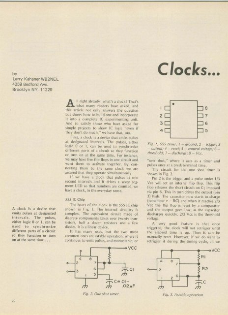
The heart o f the clock is the 555 IC chip<br />
shown in Fig. 1. The internal circuitry is<br />
complex. The equivalent circuit made of<br />
disc rete components takes over twenty transistors,<br />
half a dozen resistors and a few<br />
diodes. It is a linear device.<br />
It has many uses, bu t the two most<br />
common ones are astable operation, where it<br />
continues to emit pulses, and mo nostable, or<br />
y<br />
4 8<br />
2 7<br />
3<br />
I<br />
/:?<br />
6<br />
5<br />
I<br />
I<br />
'£<br />
;:h C"'OI<br />
.0<br />
VCC<br />
CI<br />
Clocks...<br />
2<br />
3<br />
4<br />
• pe<br />
Fig. 1. 555 timer. 1 - ground; 2 - trigger; 3<br />
- output; 4 - reset; 5 - control voltage; 6 <br />
threshold; 7 - discharge; 8 - Vee.<br />
"one shot," where it acts as a timer and<br />
pulses once at a predetermined time.<br />
The circuit for the one shot timer is<br />
shown in Fig. 2.<br />
Pin 2 is the trigger and a pulse un der '{3<br />
Vcc will set an internal flip flop . This flip<br />
flop releases the short circui t on C, imposed<br />
via pin 6. Th is in turn drives the output (pin<br />
3) high . The capacitor now starts to charge<br />
[remember T = RC) and when it reac hes 2/3<br />
Vcc the fli p flo p is rese t by a comparator<br />
and the output goes low, as the capacitor<br />
discharges quickly. 2/3 vee is the threshold<br />
voltage.<br />
A very good feature is that once<br />
tr iggered, th e clock wi ll not retrigger until<br />
t he elapsed t ime is up. Th en it can be<br />
manually rese t. However, if we do want to<br />
ret ri gger it du ring the timing cycle, a ll we<br />
RI<br />
4 8 7<br />
3 R2<br />
I<br />
J<br />
2 6<br />
;:hC<br />
Fig. 2. One shot timer. Fig. 3. Astable operation.<br />
VCC