IN THIS ISSUE -- NEW Magazine Formats! NEW FCC Regs Corning ...
IN THIS ISSUE -- NEW Magazine Formats! NEW FCC Regs Corning ...
IN THIS ISSUE -- NEW Magazine Formats! NEW FCC Regs Corning ...

You also want an ePaper? Increase the reach of your titles
YUMPU automatically turns print PDFs into web optimized ePapers that Google loves.
PROBE<br />
150n<br />
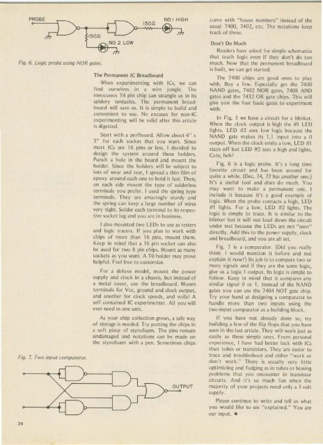
Fig. 6. Logic probe using NOR gates.<br />
Fig. 7. Two input comparator.<br />
24<br />
150 n<br />
The Permanent IC Breadboard<br />
When experimenting with ICs, we can<br />
fi nd ourselves in a wire jungle. The<br />
innocuou s 14 pin chip can strangle us in its<br />
spi dery tentacles. The permanent breadboard<br />
will save us. It is si mple to build and<br />
convenient to use. No excuses for non-IC<br />
experimenting will be valid after this article<br />
is digested.<br />
Start with a perfboard. Allow about 4" x<br />
3" for each socket that you want. Since<br />
most ICs are 16 pins or less, I decided to<br />
design the system around these holders.<br />
Punch a ho le in the board and mount the<br />
holder. Since the holders will be subject to<br />
lots of wear and tear. I spread a th in film of<br />
epoxy around each one to hold it fast. Then,<br />
on each side mount the typc of soldcrless<br />
termi nals you prefcr. I used the spring type<br />
termi nals. They are amaz ingly sturdy and<br />
the spring can keep a largc number of wires<br />
vcrv tight. Soldcr each terminal to its respective<br />
socket lug and yo u are in business.<br />
I also mounted two LEOs to use as testers<br />
and logic tracers. If you plan to work with<br />
chi ps of more than 16 pins, mount them .<br />
Keep in mind that a 16 pin socket can also<br />
be used for two 8 pin chips. Mount as many<br />
sockets as you wa nt. A TO holder may prove<br />
helpful. Feel free to customize.<br />
For a deluxe model, mount the power<br />
supply and clock in a chassis, but instead of<br />
a metal cover, use the bread board . Mount<br />
terminals for v ee, ground and clock output,<br />
and another for cloc k speeds, and voila! A<br />
self contained IC experime nte r. All you will<br />
ever need in one un it.<br />
As your chip collection grows, a safe way<br />
of storage is needed. Try putting the chips in<br />
a soft piece of styrofoam. The pins remain<br />
undamaged and notations can be made on<br />
the styrofoa m with a pen. Sometimes chips<br />
'1 ou<br />
}-J<br />
NO.1 HIGH come with "house numbers" instead of the<br />
usual 7400, 7402, etc. The notations keep<br />
track of these.<br />
TPUT<br />
Don't Do Much<br />
Readers have asked for simple sc hematics<br />
that teach logic even if they don't do too<br />
much. Now that the permanent breadboard<br />
is built, we can get star ted.<br />
The 7400 chips are good ones to play<br />
with. Buy a few. Especially get the 7400<br />
NAND gates, 7402 NOR gates, 7408 AND<br />
gates and the 7432 OR gate chi ps. This will<br />
give yo u the four basic gates to experiment<br />
with .<br />
In Fi g. 5 we have a circuit for a blinker.<br />
Wh cn the clock output is high the #1 LED<br />
lights. LEO #2 sees low logi c because the<br />
NAND gate makes its 1,1 input into a 0<br />
output. When the clock emits a low, LED #1<br />
stays off but LED #2 sees a high and lights.<br />
Cute, heh ?<br />
Fig. 6 is a logic probe . It's a long time<br />
favorite circui t and has been around for<br />
quite a wh il e. (Dec. 74, 73 has another one.)<br />
It's a useful tool and does do much. You<br />
may wan t to make a permanent one. I<br />
include it because it's a good example of<br />
logic. Whcn the probe contacts a high, LED<br />
# 1 lights. For a low, LED #2 lights. The<br />
logic is simple to trace. It is si milar to the<br />
blinker but it will not load down the circuit<br />
under test because the LEOs are not "seen"<br />
directl y. Add this to the power supply, clock<br />
and breadboard , and you are all set.<br />
Fig. 7 is a comparator. (Did you really<br />
think I would mention it before and not<br />
explain it now?) Its job is to compare two or<br />
more si gnals and if they are the same logic,<br />
give us a logic 1 output. Its logi c is simple to<br />
follow. Kcep in mind that it compares any<br />
similar signal 0 or 1. Instead of the NAND<br />
gates you can use the 7404 NOT gate chip.<br />
Try yo ur hand at design ing a comparator to<br />
handl e more than two inputs using the<br />
two-input comparator as a building block.<br />
If you have not already done so, try<br />
building a few of the flip flops that you have<br />
seen in the last articl e. They will work just as<br />
casily as these si mple ones. From personal<br />
experience, I have had better luck with ICs<br />
than tu bes or transistors. They arc easier to<br />
trace and troubleshoot and either "work or<br />
don 't work." There is usually ve ry li ttle<br />
opt imizing and fud ging as in tubes or biasing<br />
problems that you encounter in transistor<br />
circuits. And it's so much fun whcn the<br />
majority of your projects need only a 5 volt<br />
supply.<br />
Please continue to write and tell us what<br />
you would like to see "explained ," You arc<br />
our input. _