Trademarks Disclaimer FCC Warning CE Mark ... - Mondo Plast
Trademarks Disclaimer FCC Warning CE Mark ... - Mondo Plast
Trademarks Disclaimer FCC Warning CE Mark ... - Mondo Plast

Create successful ePaper yourself
Turn your PDF publications into a flip-book with our unique Google optimized e-Paper software.
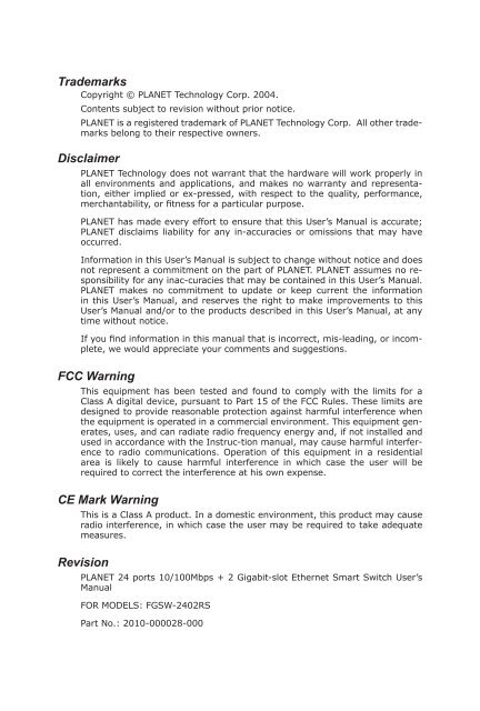
<strong>Trademarks</strong><br />
Copyright © PLANET Technology Corp. 2004.<br />
Contents subject to revision without prior notice.<br />
PLANET is a registered trademark of PLANET Technology Corp. All other trademarks<br />
belong to their respective owners.<br />
<strong>Disclaimer</strong><br />
PLANET Technology does not warrant that the hardware will work properly in<br />
all environments and applications, and makes no warranty and representation,<br />
either implied or ex-pressed, with respect to the quality, performance,<br />
merchantability, or fitness for a particular purpose.<br />
PLANET has made every effort to ensure that this User’s Manual is accurate;<br />
PLANET disclaims liability for any in-accuracies or omissions that may have<br />
occurred.<br />
Information in this User’s Manual is subject to change without notice and does<br />
not represent a commitment on the part of PLANET. PLANET assumes no responsibility<br />
for any inac-curacies that may be contained in this User’s Manual.<br />
PLANET makes no commitment to update or keep current the information<br />
in this User’s Manual, and reserves the right to make improvements to this<br />
User’s Manual and/or to the products described in this User’s Manual, at any<br />
time without notice.<br />
If you find information in this manual that is incorrect, mis-leading, or incomplete,<br />
we would appreciate your comments and suggestions.<br />
<strong>FCC</strong> <strong>Warning</strong><br />
This equipment has been tested and found to comply with the limits for a<br />
Class A digital device, pursuant to Part 15 of the <strong>FCC</strong> Rules. These limits are<br />
designed to provide reasonable protection against harmful interference when<br />
the equipment is operated in a commercial environment. This equipment generates,<br />
uses, and can radiate radio frequency energy and, if not installed and<br />
used in accordance with the Instruc-tion manual, may cause harmful interference<br />
to radio communications. Operation of this equipment in a residential<br />
area is likely to cause harmful interference in which case the user will be<br />
required to correct the interference at his own expense.<br />
<strong>CE</strong> <strong>Mark</strong> <strong>Warning</strong><br />
This is a Class A product. In a domestic environment, this product may cause<br />
radio interference, in which case the user may be required to take adequate<br />
measures.<br />
Revision<br />
PLANET 24 ports 10/100Mbps + 2 Gigabit-slot Ethernet Smart Switch User’s<br />
Manual<br />
FOR MODELS: FGSW-2402RS<br />
Part No.: 2010-000028-000
Table of Contents<br />
Chapter 1 TINTRODUCTION 1<br />
1.1 Package Contents 1<br />
1.2 About this Switch 1<br />
1.3 Product Features 2<br />
1.4 Product Specifications 2<br />
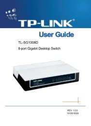
Chaper 2 HARDWARE INSTALLATION 5<br />
2.1 Font Panel 5<br />
2.2 Rear Panel 6<br />
2.3 Hardware installation 6<br />
Chapter 3 CONFIGURATION 9<br />
3.1 Connect to PC’s RS-232 serial port 9<br />
3.2 Main Menu 10<br />
3.3 Status 10<br />
3.4 Configuration 12<br />
3.5 Security 19<br />
3.6 Diagnostics 19<br />
3.7 Password 20<br />
3.8 Reboot switch 20<br />
3.9 logout 21<br />
Chapter 4 TROUBLESHOOTING 23<br />
APPENDIX A 25<br />
A.1 Switch‘s RJ-45 Pin Assignments 25<br />
A.2 10/100Mbps, 10/100Base-TX 25<br />
A.3 Cable Specification 25<br />
A.4 RJ-45 Pin assignment 26
1.1 Package Contents<br />
Check the contents of your package for following parts:<br />
• FGSW-2402RS Gigabit Ethernet Smart Switch<br />
• Power Cord<br />
• RS-232 cable<br />
• User’s Manual<br />
• Rock-mounting blackest<br />
� NOTE:<br />
1.2 About this Switch<br />
Chapter 1<br />
TINTRODUCTION<br />
if any of these pieces are missing or damage please con-tact your<br />
dialer immediately.<br />
FGSW-2402RS is a latest 10/100Mbps + 2 GbE-slot smart switch from PLANET. This<br />
switch provides 24 10/100Mbps ports and 2 Gigabit expansion slots for optional modules.<br />
FGSW-2402RS is a high performance switch that provides users with high-speed network<br />
connections with a store-and-forward architecture that is able to eliminate faulty<br />
packets.<br />
The FGSW-2402RS is equipped with a console interface and is able to manage basic<br />
switch functions such as bandwidth control, port status configuration, QOS, port trunking<br />
and VLAN parameters. The FGSW-2402RS supports auto learning and storage up to 8K<br />
of MAC addresses, as well as a non-blocking 8.8Gbps back plane for packet transmission.<br />
Also this switch supports two different types of VLAN, which are port-based VLAN and<br />
802.1Q VLAN.<br />
The switch is suitable for the following application:<br />
Workgroup switch<br />
FGSW-2402RS has 24 10/100mbps ports and 2-slot available for a 10/100Mbps<br />
Ethernet ports optional 1000SX/1000LX/1000GT module. This switch provides a high<br />
performance solution for a variety of user applications<br />
Department Switch<br />
With its 8.8 Gigabits per second, non-blocking switch fabric, the FGSW-2402RS can<br />
easily provide a local, high bandwidth network for your departmental backbone.<br />
Choice for Gigabit optic module also can be deployed to extend the network distance<br />
1
1.3 Product Features<br />
2<br />
• 24 (10/100Mbps), 2-slot (10/100/1000Mbps) Gigabit Smart Switch<br />
• Provide 8.8Gbps switch fabric, non-blocking switch architec-ture<br />
• 8K MAC address, auto-aging<br />
• 2.5Mbit as packet buffer<br />
• Store-and-forward architecture, broadcast control<br />
• 24 TP ports 10/100Mbps Auto-Negotiation<br />
• 2 expansion slots, work with MII-SX/LX, GT and FX modules<br />
• Smart function support, Port Trunk, Port status configure, VLAN<br />
• 19-inch rack mount size<br />
• Comply with IEEE802.3, IEEE802.3u 10/100Base-TX, IEEE802.3ab, IEEE802.3z<br />
1000Base-T, 1000Base-SX/LX Standard<br />
• Console interface for switch basic management and setup<br />
• Auto-MDI/MDI-X detection on each RJ-45 port<br />
1.4 Product Specifications<br />
Model<br />
Hardware Specification<br />
Ports<br />
Environment<br />
FGSW-2402RS<br />
24-port 10/100Mbps + 2 Gigabit-slot Ethernet Smart Switch<br />
24 10/100Base-TX RJ-45 Auto-MDI ports<br />
2 open slots<br />
1 RS-232<br />
Operating Temp: 5 ~ 50°C (32 ~ 122°F)<br />
Storage Temp: -40 ~ 70°C (-22 ~ 158°F)<br />
Humidity 0 ~ 90% non-condensing<br />
Dimensions 440 x 200 x 44 mm (W x D x H); 1U height<br />
Power supply 100 ~ 240V AC (± 10%), 50/60Hz (± 3%) auto-sensing<br />
Power<br />
Consumption<br />
Switch Specification<br />
Switch<br />
architecture<br />
Switch Fabric 8.8Gbps<br />
30 watts / 100BTU maximum<br />
Store-and-forward
MAC Address<br />
table<br />
8K entries, auto learning/ageing<br />
Memory 2.5Mbits for packet buffer<br />
Auto-MDI/<br />
MDI-X<br />
Support on all RJ-45 ports<br />
Flow Control Back pressure for half duplex, IEEE 802.3x for full duplex<br />
Rate Control Per port TX/RX at 128K, 256K, 512K, 1M, 2M, 4M, 8M<br />
Port Trunk 8 Trunk with up to 4port per trunk<br />
Standard / Emission<br />
Network<br />
Standards<br />
IEEE802.3 10BASE-T<br />
IEEE802.3u 100BASE-TX/100BASE-FX<br />
IEEE802.3z, ab Gigabit Ethernet 1000Base-SX/LX, 1000Base-T<br />
IEEE802.3x Flow Control<br />
IEEE802.1p Class of service<br />
IEEE802.1Q VLAN Tagging<br />
Emission <strong>FCC</strong>, <strong>CE</strong> Class A<br />
3
Chapter 2<br />
HARDWARE INSTALLATION<br />
This section is describes the hardware features and installation of the 24-port 10/100Mbps<br />
+ 2 Gigabit-slot Ethernet Smart Switch. – FGSW-2602RS<br />
FGSW-2402RS has provide two different module slots for expansion:<br />
• MII-SX - 1000Base-SX Gigabit Ethernet Module (SC, MM)<br />
• MII-LX - 1000Base-LX Gigabit Ethernet Module (SC, SM/MM)<br />
• MII-GT - 10/100/1000Mbps Ethernet Module (RJ-45 copper)<br />
• MII-ST – 100Base-FX Fast Ethernet Module (ST, MM)<br />
• MII-SC - 100Base-FX Fast Ethernet Module (SC, MM)<br />
2.1 Font Panel<br />
The font panel of the FGSW-2402RS Ethernet Smart Switch consist RS-232 console port,<br />
LED indicators, 24 10/100BaseTX RJ45 ports and two expansion slot. For the open slot,<br />
please refer to the MII module’s installation guide for the hardware installation. The front<br />
panel of the switch is as blow.<br />
LED Indication of the Switch<br />
LED Statu Descript<br />
Power<br />
LNK/ACT Green<br />
100 Orange<br />
Figure 2-1 The Font Panel of FGSW-2402RS<br />
Green Power On<br />
Off Power is not connected<br />
This indicator light green when the port is connected to<br />
an Ethernet or Fast Ethernet station, if the indicator is<br />
blinking green, it will be transmitting or receiving data<br />
on the network.<br />
This LED indicator light orange when a Fast Ethernet<br />
station is connected. It remains OFF, if an Ethernet sta-<br />
tion is connected.<br />
5
2.2 Rear Panel<br />
The Rear Panel of the Switch is indicates an AC 3 pronged power socket and I/O power<br />
switch. This switch will work with AC in the range 100-240V AC, 50-60Hz<br />
Power Receptacle<br />
6<br />
Figure 2-2 Rear Panel of FGSW-2402RS<br />
For the compatibility with electric service in most of areas, FGSW-2402RS’s power supply<br />
can automatically adjust line power in the range 100-240V AC, 50-60Hz.<br />
� NOTE:<br />
2.3 Hardware installation<br />
The Switch is a power-required device, it means, the Switch<br />
will not work until it is powered. If your networked PCs will<br />
need to transmit data all the time, please consider vuse an UPS<br />
(Uninterrupted Power Supply) for your Switch. It will prevent you<br />
from network data loss.<br />
In some area, installing a surge suppression device may also help<br />
to protect your Switch from being damaged by unregulated surge<br />
or current to the Switch or the power adapter<br />
FGSW-2402RS Ethernet Smart Switch can be placed on desktop or mounted on rock. If<br />
this Switch is used as standalone standard, the user can immediately use most of the<br />
features simply by attaching the cables and turning the power on<br />
Desktop installation<br />
To install an FGSW-2402RS on a desktop or shelf, simply complete the following steps:<br />
Step1: Attach the rubber feet to the recessed areas on the bottom of the switch.<br />
Step2: Place the FGSW-2402RS on a desktop or shelf near an AC power source.<br />
Step3: Keep enough ventilation space between the switch and the surrounding<br />
objects<br />
� NOTE:<br />
Rock-mount installation<br />
Do not obstruct any vents at the sides of the case and keep<br />
water off.<br />
To install the switch in a 19-inch standard rack, follow the instructions described below.<br />
Step1: Place your FGSW-2402RS on a hard flat surface, with the front panel posi-<br />
tioned towards your front side.<br />
Step2: Attach a rack-mount bracket to each side of the switch with supplied<br />
screws attached to the package. Figure 2-3 shows how to attach brackets<br />
to one side of the switch.
Caution:<br />
Figure 2-3 Attaching the brackets to the FGSW-2402RS<br />
Step3: Secure the brackets tightly.<br />
You must use the screws supplied with the mounting brackets.<br />
Damage caused to the parts by using incorrect screws would<br />
invalidate your warranty.<br />
Step4: Follow the same steps to attach the second bracket to the opposite side.<br />
Step5: After the brackets are attached to the switch, use suitable screws to se-<br />
curely attach the brackets to the rack<br />
7
Chapter 3<br />
CONFIGURATION<br />
The FGSW-2402RS is a Smart Ethernet Switch that can be controlled by the RS-232<br />
console interface. This chapter describer how to configure the Switch through the RS-232<br />
smart interface.<br />
3.1 Connect to PC’s RS-232 serial port<br />
When you are ready to configure the smart functions of the Switch, make sure you had<br />
connected the supplied RS-232 serial cable to the RS-232 port at the front panel of your<br />
FGSW-2402RS Switch and your PC.<br />
Hyper Terminal<br />
In Windows 98/2000/XP, launch “HyperTerminal”, create a new connection, and adjust<br />
settings as below:<br />
• Baud per second: 19200<br />
• Data bits: 8<br />
• Parity: None<br />
• Stop bits: 1<br />
• Flow Control: None<br />
9
3.2 Main Menu<br />
Login is required to access the command console after the self-test completes successfully.<br />
The factory default Username is “admin” without password<br />
Control key describe:<br />
I / M / J / L: Up / down / left / right<br />
1 / 2: Page up / Page down<br />
S: Save the configuration<br />
F: Refresh<br />
Space: Toggle selected item to change the value.<br />
0: Exit current action<br />
After type in username and press enter twice then you can see the screen as below:<br />
To enter any of sub-menus, simply type the number on the main menu.<br />
3.3 Status<br />
In this menu it shows the basic information of the Switch including, Switch overview, MIB<br />
counter and port status.<br />
10
3.3.1 Overview<br />
In this menu, there are some basic information of the Switch like, System name, Switch<br />
MAC ID, Chip Mode ID and Vender ID<br />
3.3.2 MIB Counter<br />
In this option, it shows transmit and receive counter of each port.<br />
1 / 2: Page up / Page down<br />
P / X: Start / Stop Polling<br />
F: Refresh<br />
0: Exit current action<br />
C: clear all counter<br />
T: Toggle Drop/CRC/Collision<br />
B: Toggle Byte/Packet unit<br />
11
3.3.3 Port Status<br />
In this option, it displays the real-time status of each port.<br />
0: Exit current action<br />
1/2: Page up/ Page down<br />
F: Refresh<br />
3.4 Configuration<br />
There are 8 main functions in Configuration menu, which is Port, Trunking, Global,<br />
QOS, Priority Tag Insert/Remove, VLAN Global control, VLAN member Setup and Device<br />
features.<br />
3.4.1 Port<br />
In this function, user can set up every port’s status<br />
Use I/M/J/L key to move between items<br />
12
Enabled The port can be set enable or disable mode. If the port status<br />
Speed<br />
advertisement<br />
is in disable then this port will not receive or transmit any<br />
packet. Default: enable.<br />
Set the port link speed and duplex mode base on auto-nego-<br />
tiation. Default 100M Full.<br />
Flow Control Enable or disable flow control. Default: Enable<br />
Rx Bandwidth Per port packet transmission control (128K, 256K, 512K, 1M,<br />
2M, 4M, 8M). Default: non-control.<br />
Tx Bandwidth Per port packet transmission control (128K, 256K, 512K, 1M,<br />
2M, 4M, 8M). Default: non-control.<br />
After the port setting, please press “S” to save the configuration. Then press “R” to restart<br />
the Auto-Negotiation to make the setting activated right away. Be noted, the Switch<br />
support auto-negotiation, for a device do not support auto-negotiation, please remain<br />
in 100M Full, the Switch will auto-detect the optimal speed, i.e. 100Mbps Half-duplex or<br />
10Mbps Half-duplex.<br />
3.4.2 Trunking<br />
In this function, user is able to enable or disable Trunking at each group. (8 trunks group<br />
base on ports)<br />
13
Be noted, the Switch at the other end should also turn on the port-based trunk with the<br />
same port number to get the optimal usage of the trunk-bandwidth.<br />
3.4.3 Global<br />
In this function, user is able to enable/disable the global setting of the Switch’s ports.<br />
Options includes, Half-duplex back Pressure flow, Broadcast Storm Filtering Control and<br />
Loop Detect<br />
14<br />
Half duplex back<br />
pressure flow<br />
Broadcast storm<br />
filtering control<br />
Loop Detect<br />
Enable or disable half duplex backpressure flow. To dis-<br />
able will turn off the half-duplex back pressure control and<br />
drop the packets without sending out any collision from the<br />
switch port.<br />
Default: Enable<br />
Enable or disable broadcast storm filtering. Enable will turn<br />
on the capability to drop broadcast packets after a continu-<br />
ous 64 broadcast packets.<br />
Default: Disable.<br />
Enable or disable loop detect function. To turn on will loop<br />
detect the connection status. This feature is used for diag-<br />
nose purpose.<br />
Default: Disable.
3.4.4 QOS<br />
In this function, user is able to enable TOS/Diff Serv Priority, 802.1p priority; adapted flow<br />
control, Priority weight ration (high: low) and Force set high-priority port.<br />
TOS/Diff Serv<br />
priority<br />
802.1p priority<br />
Adapted flow<br />
control<br />
Priority weight<br />
ration (high:<br />
low)<br />
Force set high-<br />
priority port<br />
Enable or disable TOS priority. Check the packets’ IP TOS<br />
priority tag and base on the priority to forward the packets.<br />
Default: Disable<br />
Enable or disable 802.1p priority. Check the packet’s 802.1p<br />
priority and base on the priority to forward the packets. De-<br />
fault: Disable.<br />
Enable or disable priority of flow control. Check the priority<br />
and turn off the flow-control when high priority packets re-<br />
ceived. Default: Disable.<br />
Use M key to move down to Priority weight ration then use<br />
Space key to select the ration priority. Available weights, 1:<br />
0; 4:1, 8:1, 16:1. Default: 16:1.<br />
Use M key to move down the cursor and select the ports,<br />
by Space toggle, that you would like to set base on the QoS<br />
options above.<br />
Be noted, the switch support dual priority per port, the QoS setting will base on the menu<br />
above to arrange each port’s high/low priority.<br />
15
3.4.5 Priority tag Insert/Remove<br />
In this menu, user is able to insert or remove Priority tag each port. The option includes:<br />
Insert Tag (high priority only), Insert Tag (all frame), Remove Tag and Don’t Touch.<br />
Please also refer to VLAN section 3.4.6 and 3.4.7 for more.<br />
16<br />
Insert Tag<br />
(high priority only):<br />
Insert Tag<br />
(all frame):<br />
Insert priority tag into the untagged high-priority frame<br />
Insert priority tag into the all untagged frame<br />
Remove Tag: Remove the VLAN tag from all tagged frame<br />
Don’t touch: The default setting, which means no modify<br />
3.4.6 VLAN Global Control<br />
This menu is allow user to enable VLAN’s global capabilities including, VLAN function,<br />
Unicast packet Inter-VLAN Leaky, ARP broadcast packet Inter-VLAN Leaky, IP Multicast<br />
packet Inter-VLAN Leaky, 802.1Q VLAN tag aware, Ingress Rule for Acceptable frame type<br />
and Ingress Rule for Ingress Filtering.<br />
VLAN function Enable VLAN, Default disable<br />
Unicast packet<br />
Inter-VLAN Leaky<br />
ARP broadcast<br />
packet Inter-VLAN<br />
Leaky<br />
IP Multicast packet<br />
Inter-VLAN Leaky<br />
802.1Q VLAN tag<br />
aware<br />
Enable the packet to be forward to a destination port at<br />
different VLAN. Default: disable<br />
Enable ARP frame to broadcast to all switch port<br />
Default: disable<br />
Enable multicast to be flood to all the multicast group<br />
member. Default: disable<br />
Enable 802.1Q VLAN tag. Default: disable
Ingress Rule for<br />
Acceptable frame<br />
types<br />
Ingress Rule for<br />
Ingress filtering<br />
� Notice:<br />
To permit all frames or VLAN-tagged frames only. Default:<br />
Admin all frames<br />
Enable filter the frame received from a port which port<br />
is not in the classified VLAN group member. Default:<br />
disable<br />
3.4.7 VLAN Member Setup<br />
Ingress rule only for 802.1Q VLAN mode<br />
This menu is for user to add VLAN member to each port. The Switch supports up to 32<br />
VLAN groups for port-based VLAN and 802.1q tag VLAN.<br />
1. Press number 7 from Configuration menu for VLAN Member setup<br />
2. Press E to change to edit mode<br />
3. Press A to add VLAN<br />
Setup a PORT based VLAN:<br />
4. Press Space key to change to port-base VLAN<br />
5. Use L key move to the Port (VLAN member)<br />
6. Press Space key to add VLAN group<br />
7 After complete the configuration Press Enter to Update VLAN<br />
8. Press S to save the configuration<br />
17
Setup a 802.1Q VLAN:<br />
Follow from Step 1 to Step 3 above<br />
18<br />
4. Press Space key to change to 802.1Q mode<br />
5. Use L key move to the right hand side<br />
6. Move to VLAN ID then Press Enter to add VLAN ID<br />
7. Move to the Port Press Space key to add VLAN group<br />
8. After complete the configuration Press Enter to Update VLAN<br />
9. Press S to save the configuration<br />
After the setup of port’s VLAN above, the Switch will base on global VLAN setting<br />
(section 3.4.6) and VLAN tag priority insertion (section 3.4.5) and the VLAN setting here<br />
to filter/forward the packets to each switching port. Please also consult your network<br />
administrator for the detailed VLAN plan of the network.<br />
3.4.8 Device Feature<br />
This function is allow user to enable IGMP Snooping and display the IP multicast router<br />
port
IGMP Snooping<br />
3.5 Security<br />
Enable IGMP Snooping. This function is support the ability of<br />
IGMP Control packets and IP multicast data packets to learn<br />
the multicast router port and group address member port<br />
into multicast address table. Default is disable.<br />
This function is for Future management purpose.<br />
3.6 Diagnostics<br />
This function is to display the information about Trunk link and Network loop<br />
Trunk link<br />
warning<br />
Network loop<br />
fault port<br />
detected<br />
Display the information about trunk at each group when<br />
trunk is enabled.<br />
Display the information loop detect when loop occur on each<br />
port.<br />
19
3.7 Password<br />
This function is allow user to modify username and password. The factory default<br />
Username is “admin” without password<br />
20<br />
Press number 5 from the main menu to select password<br />
Press 1 to modify the username<br />
Press 2 to modify the password<br />
3.8 Reboot switch<br />
In this function, it provides two different reboot functions which is to reset the switch to<br />
Default and restart switch<br />
Press number 6 from main menu to select reboots<br />
Press D to reset the switch to default setting and reboot.<br />
Press R to restart switch right away.
3.9 logout<br />
Logout the switch<br />
Press number 7 from the main menu will logout to the switch.<br />
After Press number 7 you can see logout screen as below. If you press enter again, the<br />
Switch will prompt login screen again.<br />
21
Chapter 4<br />
TROUBLESHOOTING<br />
This chapter contains information to help you solve problems. If Switch is not functioning<br />
properly, make sure the Ethernet Switch was set up according to instructions in this<br />
manual.<br />
The Link LED is not lit<br />
Solution:<br />
Check the cable connection and duplex mode of the Switch. Port 1 to Port 24<br />
of the switch support 10/100Mbps auto-negotiation, the connected end should<br />
also support auto-negotiation, if not, it will work at 10 Half or 100 Half.<br />
The cable distance is within 100meters Cat. 3 or above EIA568 cable with 2pair<br />
or 4-pair.<br />
For port 25, 26 of the switch, it will vary on the module installed. For<br />
1000Base-T interface, Cat.5/5e cable with 4-pair below 100 meters is required.<br />
For 1000Base-SX, multi-mode 62.5/125 or 50/125μm below 220/550<br />
meters. And 10/125 or 9/125μm single mode cable 10km is allowed.<br />
Some stations cannot talk to other stations located on<br />
The other port<br />
Solution:<br />
The address table may contain older information than of the address table of<br />
that node. Please power down to refresh the address information.<br />
Performance is bad<br />
Solution:<br />
Check the full duplex status of the Ethernet Switch. If the Ethernet Switch is<br />
not at the same duplex mode, then the performance will be poor.<br />
Console can not display<br />
Solution:<br />
Check the connection between the PC and the Switch. Please use the supplied<br />
console cable to connect the two ends firmly.<br />
Then check the COM port (1 or 2) and baudrate of the terminal program, it<br />
should be 19200, n, 8, 1.<br />
If you are using HyperTeminal, please exit the program and restart again.<br />
Then power off, and power on the Switch. The Switch should prompt the login<br />
screen.<br />
In many cases, 10Base-T LANs can quickly and easily upgrade to 100Base-TX<br />
networks.<br />
23
A.1 Switch‘s RJ-45 Pin Assignments<br />
1000Mbps, 1000Base T<br />
Contact MDI MDI-X<br />
1 BI_DA+ BI_DB+<br />
2 BI_DA- BI_DB-<br />
3 BI_DB+ BI_DA+<br />
4 BI_DC+ BI_DD+<br />
5 BI_DC- BI_DD-<br />
6 BI_DB- BI_DA-<br />
7 BI_DD+ BI_DC+<br />
8 BI_DD- BI_DC-<br />
Appendix A<br />
Implicit implementation of the crossover function within a twisted-pair cable, or at a<br />
wiring panel, while not expressly forbidden, is beyond the scope of this standard.<br />
A.2 10/100Mbps, 10/100Base-TX<br />
Contact MDI MDI-X<br />
1 1 3<br />
2 2 6<br />
3 3 1<br />
6 6 2<br />
The TP ports of the Switch supports Auto-MDI detection, if the connected device is MDIdevice<br />
like Ethernet Adapter, the Switch all auto adjust the contact to MDI-X. In contrast,<br />
if the connected end is MDI-X, the Switch will adjust to MDI.<br />
A.3 Cable Specification<br />
Straight through cable<br />
25
Cross over cable<br />
A.4 RJ-45 Pin assignment<br />
26