

MONITOR GF 3800 Vented Heating Systems - HouseNeeds, Inc.
MONITOR GF 3800 Vented Heating Systems - HouseNeeds, Inc.
MONITOR GF 3800 Vented Heating Systems - HouseNeeds, Inc.

You also want an ePaper? Increase the reach of your titles
YUMPU automatically turns print PDFs into web optimized ePapers that Google loves.
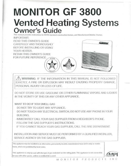
<strong>MONITOR</strong> <strong>GF</strong> <strong>3800</strong><br />
<strong>Vented</strong> <strong>Heating</strong> <strong>Systems</strong><br />
Owner's Guide<br />
This manual provides instructions (or BOTH standard construction homes, and Manufactured (Mobile } homes.<br />
IMPORTANT:<br />
READ THIS OWNER'S GUIDE<br />
CAREFULLY AND THOROUGHLY<br />
BEFORE INSTALLING OR USING<br />
YOUR HEATER.<br />
RETAIN THIS OWNER'S GUIDE<br />
FOR FUTURE REFERENCE.<br />
WARNING: IF THE INFORMATION IN THIS MANUAL IS NOT FOLLOWED<br />
EXACTLY, A FIRE OR EXPLOSION MAY RESULT CAUSING PROPERTY DAMAGE,<br />
PERSONAL INJURY OR LOSS OF LIFE.<br />
DO NOT STORE OR USE GASOLINE OR OTHER FLAMMABLE VAPORS AND LIQUIDS<br />
IN THE VICINITY OF THIS OR ANY OTHER APPLIANCE.<br />
WHAT TO DO IF YOU SMELL GAS<br />
DO NOT TRY TO LIGHT ANY APPLIANCE.<br />
DO NOT TOUCH ANY ELECTRICAL SWITCH; DO NOT USE ANY PHONE IN YOUR<br />
BUILDING.<br />
IMMEDIATELY CALL YOUR GAS SUPPLIER FROM A NEIGHBOR'S PHONE.<br />
FOLLOW THE GAS SUPPLIER'S INSTRUCTIONS.<br />
IF YOU CANNOT REACH YOUR GAS SUPPLIER, CALL THE FIRE DEPARTMENT.<br />
INSTALLATION AND SERVICE MUST BE PERFORMED BY A QUALIFIED INSTALLER,<br />
SERVICE AGENCY OR THE GAS SUPPLIER.<br />
This appliance may be installed in an aftermarket. permanently located, manufactured home (USA only) or mobile<br />
home, where not prohibited by local codes.<br />
This appliance is only for use wilh the type of gas indicated on the rating plate. This appliance is not convertible<br />
for use with other gases, unless a certified kit is used.<br />
M O N I T O R P R O D U C T S N C
SAFETY ALERT SYMBOL<br />
These symbols appear as important safety precautions and should be understood<br />
and followed by the owner to assure safe operation of the heater.<br />
For Quick Reference<br />
Page<br />
SECTION A: Important Caution 1<br />
SECTION B: Specifications -. 5<br />
Special Features - 5<br />
Safety Features : 5<br />
SECTION C: Tools Needed for Heater Installation 6<br />
Accessories You May Need ; • 7<br />
Flue Pipe Extensions 8<br />
SECTION D: Notice Before Installation 9<br />
Heater Installation : 10<br />
Flue Pipe Clearances • 11<br />
SECTION E: Gas Connection 16<br />
SECTION F: Operating Instructions • 17<br />
Starting'lnstructions 18<br />
Adjusting Room Temperature 18<br />
Turning Off the Heater 19<br />
Relighting the Heater 19<br />
Programming the Heater : 19<br />
Programming for Automatic Heater Operation • 20<br />
Manual Operation 20<br />
SECTION G: Protective Features 21<br />
Loss of Power-Automatic Reset, Child Lock 21<br />
Electrical Fuse 21<br />
Overheat Prevention 21<br />
SECTION H: Maintenance and Check 22<br />
SECTION I: Trouble Shooting Guide 23<br />
SECTION J : Wiring Diagram- '••-••24-<br />
Block Diagram -24<br />
SECTION K: Parts List 26<br />
COPYRIGHT © <strong>MONITOR</strong> PRODUCTS, INC.,
SECTION A<br />
WARNING<br />
IMPROPER INSTALLATION, ADJUSTMENT, ALTERATION, SERVICE OR<br />
MAINTENANCE CAN CAUSE PROPERTY DAMAGE, PERSONAL INJURY OR LOSS OF<br />
LIFE, REFER TO THE OWNER'S INFORMATION MANUAL PROVIDED WITH THIS<br />
APPLICANCE.<br />
INSTALLATION AND SERVICE MUST BE PERFORMED BY A QUALIFIED<br />
INSTALLER, SERVICE AGENCY OR THE GAS SUPPLIER,<br />
THIS PRODUCT MUST BE INSTALLED BY A LICENSED PLUMBER OR GAS FITTER<br />
WHEN INSTALLED WITHIN THE COMMONWEALTH OF MASSACHUSETTS.<br />
CAUTION<br />
Make sure that flue pipe (exhaust pipe, air supply hose) is<br />
connected properly.<br />
Keep heater clean and do not store any flammable items on or<br />
near the heater.
Don't use the heater for drying clothes.<br />
Should anything abnormal occur in the heater, remain calm,<br />
turn it off (do not unplug) and contact your Monitor dealer.<br />
Risk of burns.<br />
Flue pipe and louver may have high surface<br />
temperature.<br />
Do not place yourself or others too close to the heater.<br />
Installation of heater in extreme humidity or dust areas is not<br />
recommended.<br />
Any removal of unit parts or remodeling is strictly forbidden.<br />
Do not sit on the heater.<br />
Placing ornaments or plants on the heater is not recommended.<br />
Excess heat may cause damage to ornament or plant and<br />
overwatering or spilling of water may cause shock to you or<br />
damage to the heater.
Don't spray aerosols on the heater when in operation.<br />
Don't allow children to insert articles in the louvers.<br />
Keep flammable materials, trees, shrubs etc. away from flue pipe.<br />
Do not vent unit into other rooms. Flue pipe must be outside.<br />
Do not install nor exhaust the flue pipe into a crawl space or underneath floor nor into a flue or<br />
chimney.<br />
k<br />
I//<br />
-Flue<br />
or<br />
Chimney
• In areas of heavy snow accumulation, the flue pipe may need to be installed higher to avoid being buried.<br />
In open areas with strong wind, a wind break may be necessary to avoid exhaust gases being blown<br />
back into the intake and causing poor combustion.<br />
Long<br />
Extension<br />
kit<br />
Must be higher.<br />
Exhaust pipe must be kept clear of flammable materials.<br />
This heater is not designed to be built in.<br />
1<br />
eS<br />
J1)<br />
fr-<br />
(60cm) i<br />
I
SECTION B<br />
SPECIFICATIONS<br />
Model No. <strong>GF</strong> <strong>3800</strong><br />
Type of Appliance Fan type direct vent wall furnace<br />
Input Rating Nat. Gas 38,000 BTU/hour<br />
LP. Gas 34,500 BTU/hour<br />
Output Rating Nat. Gas 30,700 BTU/hour<br />
LP. Gas 27,900 BTU/hour<br />
Efficiency 83%<br />
Electrical Rating 120V, 60Hz, Less than 2 amperes<br />
Power Consumption 80 Watts<br />
Heated Air Delivery High 388 Cubic feet/minute<br />
Low 300 Cubic feet/minute<br />
Flue Pipe Hole 2.5 inches diameter<br />
Dimensions Height: 26.6 inches (67.56cm)<br />
Width: 28.7 inches (72.90cm)<br />
Depth: 14.0 inches (35.50 cm)<br />
Weight 82 pounds<br />
Inlet Gas Supply Pressure Nat. Gas Max. 10.5 inch W.C. (267 mmHzO)<br />
Min. 5.1 inch W.C. (130 mmHaO)<br />
LP. Gas Max. 13.0 inch W.C. (330 mmHzO)<br />
Min. 11.0 inch W.C. (279 mmH2O)<br />
Manifold Test Pressure Nat. Gas 3.4 inch W.C. (86 mmHzO)<br />
LP. Gas 3.!5inch W.C. (80mmH2O)<br />
The minimum and maximum inlet gas supply pressure are for the purpose of input adjustment.<br />
The efficiency rating of this appliance is a product of thermal efficiency rating determined under<br />
continuous operating conditions and was determined independently of any installed system.<br />
SPECIAL FEATURES<br />
AUTOMATIC IGNITION<br />
MEMORY BACK UP: Set memory can be kept in case of<br />
power failure for up to30minutes.<br />
DUAL BLOWERS: Separate fans for combustion and<br />
room air circulation.<br />
THERMOSTATICALLY CONTROLLED: Adjusts to the<br />
desired room temperature.<br />
BUILT-IN TIMER: Heater will automatically operate as<br />
programmed by the user.<br />
AUTOMATIC RESET AFTER POWER FAILURE: Heater<br />
will automatically resume operation after power is<br />
restored.<br />
INDICATOR LIGHTS: Easy-to-see signals show when<br />
heater is in operation, when timer is activated, and<br />
when the burner is operating.<br />
CLEAN OPERATION: Products of combustion are vented<br />
outside.<br />
CONSUMES NO ROOM AIR: Air for combustion is drawn<br />
from outside.<br />
EASY INSTALLATION: <strong>Inc</strong>ludes all parts required for<br />
standard installation.<br />
SAFETY FEATURES<br />
SAFE RE-LIGHTING: Heater will not restart until its<br />
combustion chamber has cooled.<br />
ELECTRICAL PROTECTION: Heater automatically shuts<br />
off in the unlikely event of a malfunction in the electrical<br />
circuitry or disruption of the power supply.<br />
NO EXHAUST IN ROOM: Products of combustion are<br />
discharged outdoors.<br />
FLUE PIPE: Outside air is drawn through a pipe-withina-pipe<br />
venting system. This process preheats<br />
combustion air and regains heat from exhaust gases.<br />
/|\ CAUTION: ALTERNATE POWER SOURCES<br />
The Monitor <strong>GF</strong><strong>3800</strong> may not operate when powered<br />
by sources such as an auxiliary generator, UPS<br />
(Uninterrupted Power Source), inverters, etc.<br />
Check with your dealer for guidance on specific<br />
applications.
SECTION C<br />
Before installing your heater, be sure to check and comply with local and state building and electrical codes<br />
that may apply to vented heaters in your area. Permanent wiring must be installed by a licensed electrician.<br />
TOOLS NEEDED FOR HEATER INSTALLATION<br />
Check the following charts to be sure you have all the tools required to install your Monitor <strong>GF</strong><strong>3800</strong> <strong>Heating</strong> System.<br />
STANDARD TOOLS APPLICATION<br />
Phillips Head Screwdriver Installation of Heater Parts<br />
Steel Tape Measure Taking Measurements<br />
Pen or Pencil Marking Drilling Location<br />
Exterior Caulk Caulking Between Packing and Wall<br />
Yardstick or Long Straight Edge Checking Angle of Hole for Flue Pipe<br />
Soapy Water Lubricating Sleeve Hardware '<br />
SPECIAL TOOLS APPLICATION<br />
Electric Drill Accommodating Hole Saw and Drill Bit<br />
2 V? inch Hole Saw Attachment Cutting Hole for Flue Pipe<br />
Long 'A inch Drill Bit Drilling Pilot Hole Through Wall<br />
Level Checking Angle of Hole for Flue Pipe and for checking heater<br />
level.<br />
Fig. 1
ACCESSORIES YOU MAY NEED<br />
Check the list below and see your MPI dealer for accessories you may need or want for installation of your heatingsystem.<br />
/!\ CAUTION: Only use the flue pipe supplied with the Monitor <strong>GF</strong>SS^or the approved accessory kits available from<br />
your Monitor or dealer.<br />
ACCESSORY APPLICATION<br />
Medium Adjustable Flue Pipe Kit P/N 8051<br />
Long Adjustable Flue Pipe Kit P/N 8052<br />
Extra Short, Short, Medium or<br />
Long Extension Kit or Elbow Adapter Kit<br />
(See Flue Pipe Extensions, page 8)<br />
For use where wall thickness is up to 12 1 A inches(31.5cm)<br />
For use where wall thickness is up to 20 inches C50.5cm)<br />
For use where "standard" installation is not practical
FLUE PIPE EXTENSIONS<br />
Four standard extension kits are available from your<br />
Monitor dealer. Most installations can be made with<br />
one of these kits. In special cases, custom installations<br />
may be required. These may be made with components<br />
purchased from your dealer.<br />
In any installation the following limitations MUST NOT<br />
BE EXCEEDED:<br />
1. Trie total length of the intake or exhaust pipe should<br />
not exceed 10 feet (3.05m) with 3 elbows, 13 feet<br />
(3.96m) with 2 elbows, or 16'/2 feet (5.3m) with 1 elbow.<br />
Exhaust Elbow<br />
90° Joint<br />
Fig. 2<br />
2. These elbows should include the one used at the<br />
heater but not the one on the air supply hose nor the<br />
integral bends in the flue pipe. (See Figure 2)<br />
3. The correct damper as shown on Page 14 must be<br />
used.<br />
4. Follow carefully the instruction included with each<br />
kit.<br />
Air Supply Hose<br />
Flue Pipe<br />
Do not count
SECTIOND<br />
NOTICE BEFORE INSTALLATION<br />
The heater must be installed by a qualified service<br />
person according to this installation instruction .<br />
The installation must conform with local codes or, in the<br />
absence of local codes, the National fuel Gas Code,<br />
ANSIZ223.1/NFPA54.<br />
The installation must conform with local codes or, in the<br />
absence of local codes, the current CAN 1-B149<br />
INSTALLATION CODE.<br />
For mobile housing and recreational vehicle installation the<br />
current Standard" CSA Z 240.4 GAS EQUIPPED<br />
RECREATIONAL VEHICLES AND MOBILE HOUSING.<br />
A manufactured home (mobile home) installation must<br />
conform with the Manufactured Home Construction<br />
and Safety Standard, Title 24 CFR, Part 3280, or, when<br />
such a standard is not applicable, the Standard for<br />
Manufactured Home installations, ANSI A 225.1/NFPA<br />
501A.<br />
Due to high temperatures, the appliance should be<br />
located out of traffic and away from furniture and<br />
draperies.<br />
Children and adults should be alerted to the hazards of<br />
high surface temperatures and should stay away to<br />
avoid burns or clothing ignition.<br />
Young children should be carefully supervised when<br />
they are in the same room as the appliance.<br />
Clothing or other flammable material should not be<br />
placed on or near the appliance.<br />
Make sure that the flow of combustion and ventilation<br />
air is not obstructed.<br />
Any safety or guard removed for servicing an appliance<br />
must be replaced prior to operating the appliance.<br />
/!\ WARNING<br />
Do not operate appliance with the panel removed,<br />
cracked or broken. Replacement of the panel should be<br />
done by a licensed or qualified service person.<br />
For manufactured home (USA only) or mobile home or<br />
residential installation convertible for use with natural,<br />
gas and liquefied petroleum gases when provision is<br />
made for the simple conversion from one gas to the other.<br />
Installation and repair should be done by a qualified<br />
service person. The appliance should be inspected<br />
before use and at least annually by a qualified service<br />
person. More frequent cleaning may be required due to<br />
excessive lint from carpeting, bedding material, etc. It is<br />
imperative that control compartments, burners and<br />
circulating air passageways of the appliance be kept<br />
clean.<br />
Do not use this heater if any part has been under water.<br />
Immediately call a qualified service technician to inspect<br />
the heater and to replace any part of the control system<br />
and any gas control which has been under water.<br />
The appliance, when installed, must be electrically<br />
grounded in accordance with local codes or, in the<br />
absence of local codes, with the National Electrical<br />
Code, ANSI/NFPA 70 .<br />
The appliance, when installed, must be electrically<br />
connected and grounded in accordance with local codes<br />
or, in the absence of local codes, with the current CSA<br />
C22.1 CANADIAN ELECTRICAL CODE.<br />
WARNING<br />
THIS APPLIANCE IS EQUIPPED WITH A THREE-PRONG<br />
(GROUNDING) PLUG FOR YOUR PROTECTION<br />
AGAINST SHOCK HAZARD AND SHOULD BE<br />
PLUGGED DIRECTLY INTO A PROPERLY GROUNDED<br />
THREE-PRONG RECEPTACLE. DO NOT CUT OR<br />
REMOVE THE GROUNDING PRONG FROM THIS PLUG.<br />
/i\WARNING<br />
IN MANUFACTURED/MOBILE HOMES WIRED FOR<br />
120/240V, ENSURE THAT THE <strong>GF</strong><strong>3800</strong> IS ONLY<br />
PLUGGED INTO A 120 VOLT CIRCUIT.<br />
A CAUTION<br />
Before converting the <strong>GF</strong><strong>3800</strong> gas type (to Liquid<br />
Propane or Nat Gas), Read instructions in Section E,<br />
Page 16.
HEATER INSTALLATION<br />
Step 1: Fill Out Owner Registration Card<br />
Remove your owner registration card from the plastic<br />
envelope containing the owner's guide. It should be<br />
filled out and mailed as soon as possible.<br />
Step 2: Check for Parts<br />
Before discarding packing materials, be sure you have<br />
located the following:<br />
Manual Gas Valve<br />
Conversion Kit<br />
Flue Pipe<br />
Sleeve Nut<br />
Tray<br />
Room Temp. Sensor (attached to the rear of the<br />
heater)<br />
Cardboard Template<br />
"STANDARD" Damper<br />
"EXTENSION" Damper<br />
Wall Clamps (2)<br />
Rubber Packing<br />
Joint Pipe<br />
Cloth Insulation Cover<br />
Outer Flange<br />
Pipe Holder<br />
Small Bag of Screws<br />
Tapping, Type A - #8x 3 A<br />
Tapping, Type A - #8x 5 /ie<br />
SIZE<br />
(}££Q£XX><br />
For securing<br />
sleeve and<br />
wall clamps<br />
#8 X 3/4<br />
Tapping<br />
Fig. 3<br />
(Jxxs><br />
For securing<br />
wall clamps<br />
#8 X Vie<br />
Tapping<br />
Step 3: Choose a Location for Your Heater<br />
In choosing a location for your heater, the following<br />
guidelines must be considered:<br />
•The heater may be installed on combustible flooring on<br />
the metal tray provided.<br />
•The area around the heater should be free of obstacles<br />
that might interfere with the free flow of air. Allow the<br />
clearances shown in Figure 4.<br />
•The heater must not be installed in a fireplace.<br />
•An AC wall outlet must be within reach of the heater's<br />
power cord. Extension cords must not be used.<br />
•The area outside where the flue pipe will emerge should<br />
be free of foliage, fuel storage tanks and flammable<br />
objects. Air should circulate freely in the area. Allow the<br />
clearances shown in Rgure 6 on the next page.<br />
•Refer to Figure 4 to provide adequate accessibility clearances<br />
for servicing.<br />
10<br />
•The wall where flue pipe hole will be cut should be free of<br />
plumbing pipes, electrical wires, studs, air ducts and other<br />
obstacles.<br />
NOTE: Use the cardboard template provided with your<br />
heater for flue pipe location.<br />
Fig. A<br />
( 99.06 cm)<br />
Step 4: Drill a Pilot Hole<br />
NOTE:The following directions apply to "standard"<br />
installation. For other methods, follow instructions<br />
included with accessory kits.<br />
For walls up to 8'/z inches (22.0cm) thick, use a<br />
standard flue pipe; for walls up to 12 '/z inches<br />
(31.5cm) thick, use a medium adjustable flue pipe<br />
kit; and for walls up to 20 inches (50.5cm) thick,<br />
use a long adjustable flue pipe kit.<br />
Use the template to position the hole to be drilled. The<br />
"blue dot" indicates the exact center of the hole. Using<br />
an electric drill and a long drill bit, make a pilot hole<br />
through the wall (Figure 5). Be sure the hole extends<br />
through the outside wall.<br />
Positic n nf h
FLUE PIPE CLEARANCES<br />
• Vent terminal must be located at least 3 feet above any forced air inlet located within 10 feet.<br />
• The vent terminal of a direct vent appliance with an input of 50,000 Btu per hour or less shall be located at least 9<br />
inches from any opening through which flue gases could enter a building, and such an appliance with an input over<br />
50,000 Btu per hour shall require a 12-inch vent termination clearance. The bottom of the vent terminal and the air<br />
intake shall be located at least 12 inches above grade.<br />
• Flue pipe installations should provide for venting to a confined space through which there is a free flow of outdoor<br />
air. Clearances to adjacent walls or obstacles must comply with the requirements shown below.<br />
Frontal Clearance<br />
/ts ll\ CAUTION :<br />
Do not attach anything onto the outlet<br />
of the flue pipe.<br />
Overhead Clearance<br />
Combustible<br />
IMPORTANT:<br />
Combustible """"'"""'"i" minimim<br />
f<br />
24' (61cm)<br />
or more<br />
Non-combustible<br />
Combustible<br />
Ground or slab surface<br />
(1) In areas of heavy snow falls, ground surface clearance<br />
must be increased according to average snow falls, to<br />
prevent flue pipe from being buried.<br />
Long<br />
Extension<br />
kit<br />
Musi be higher.<br />
Body -<br />
Clamp<br />
Fig. 6<br />
(13.5cm)<br />
Heater<br />
Side Clearance<br />
Heater-<br />
-Wall<br />
3"<br />
Any construction<br />
above Flue Pipe<br />
(7.5 must not come _<br />
cm) within 24" (60cm)<br />
Of<br />
more<br />
of front obstacle<br />
24'(60cm)<br />
or more<br />
_Flue Pipe<br />
Front Obstacle<br />
8" (20cm)<br />
or more<br />
Ground or slab surface<br />
Body<br />
Clamp<br />
Side obstacle<br />
iniimnlllliiinimmiHiiiiHill<br />
18' (45cm)<br />
or more<br />
Flue Pipe<br />
-Wall<br />
(2) In open area with strong wind, a wind break may be<br />
necessary.<br />
— 24"min<br />
(61 cm)<br />
11
\z<br />
Step 5: Cut the Hole for the Flue pipe<br />
Using a hole saw attachment and an electric drill, cut a 2'/2<br />
inch diameter hole through the inner and outer walls<br />
(Figure 7).<br />
After the hole is cut, use a straight edge and a level to<br />
be sure the inside opening is approximately 'A inch<br />
higher than the outside opening.<br />
NOTE: After cutting the inside wall, remove the<br />
insulation. Make sure there are no obstructions<br />
inside the wall, such as electrical wiring, water<br />
pipes, hot air ducts, etc.<br />
Fig. 7<br />
(6.35cm)<br />
.V.'J Outdoof<br />
(0.64cm)<br />
Step 6:The Flue Pipe is two Sections, Flue Pipe A<br />
and Flue Pipe B<br />
Install the Flue Pipe A<br />
From INSIDE the building, insert the flue pipe A (with<br />
arrow pointing "up") into the hole. Fasten the flue pipe<br />
with the 3#8X 3/4 tapping screws (Figure8and 9 ).<br />
(See Figure for screw size and application.)<br />
NOTE: Top center port is an extra exhaust port.<br />
Fig. 8<br />
tapping screw<br />
Flue Pipe A<br />
Room<br />
Fig. 9<br />
1/4-<br />
(0.6 4 c-*)
Step 7:lnstall Flue Pipe B<br />
Wall Thickness: 5-8'/? inches<br />
1. Slide the outer flange and the rubber packing onto<br />
Flue pipe B. (Figure 10)<br />
Rubber Packing Outer Flange<br />
Rubber Packing Outer Flange<br />
Fig. 10<br />
Flue Pipe B<br />
2. Spread caulking material on the inside of the rubber<br />
packing if required. (Figure 11)<br />
Fig. 11<br />
Rubber Packing<br />
3. It is imprlant to keep the "UP" mark on the rubber<br />
packing at the top while screwing in Flue pipe B. Hold<br />
the packing in place while screwing in Flue pipe B<br />
until it is the tight. (Figure 12)<br />
Rubber Packing<br />
Fig. 12<br />
Flue Pipe B<br />
Wall Thickness: 3 /s -5 inches<br />
1. Set the Sleeve nut onto Flue Pipe B by turning the<br />
Sleeve Nut counter-clockwise. Slide the Outer Flange<br />
and the Rubber Packing onto Flue Pipe B.<br />
(Figure 13)<br />
Rubber Packing<br />
Outer Flange<br />
y,\ , ~<br />
Rubber Packing<br />
Sleeve Nut<br />
Fig. 13<br />
Outer Flange<br />
Sleeve Nut<br />
Flue Pipe B<br />
2. Spread caulking material on the inside of the Rubber<br />
Packing if required. (Figure 11)<br />
3. It is important to keep the "UP" mark on the Rubber<br />
Packing at the top while screwing in the Flue Pipe B.<br />
Hold the Rubber packing in place while screwing in<br />
the Flue Pipe B until it is the tight. (Figure 12)<br />
4. Turn the Sleeve Nut clockwise and tighten.<br />
(Figure 14)<br />
Flue Pipe A<br />
Rubber Packing<br />
/ Outer Flange<br />
Fig. 14<br />
Sleeve Nut<br />
Flue Pipe B<br />
13
14<br />
Step 8: Level the cabinet<br />
Place tray on the floor where you plan to locate<br />
your heater.<br />
Position the heater on the tray so the legs of the<br />
cabinet fit into the circular indentations in the tray.<br />
In order for heater to operate properly. It must be<br />
positioned on a level surface. Ensure proper leveling by<br />
adjusting each leg and by using a carpenters level to<br />
check both side to side, and front to back level<br />
condition. (Figure 15)<br />
Fig. 15<br />
Legs Tray<br />
Step 9: Install the Joint Pipe<br />
At the rear of the heater, slide the large end opening of<br />
the joint pipe into the exhaust port outlet of the heater.<br />
Be sure the joint pipe is fully seated. Slide the cloth<br />
insulation cover over the joint pipe (Figure 16).<br />
The o-rings that seal the joint pipe may be dry and<br />
tight. A little soapy water will ease installation.<br />
Fig. 16<br />
Cloth Insulation<br />
Cover<br />
Joint Pipe<br />
Step 10: Connect the Heater to the Flue Pipe<br />
Move the heater toward the wall, guiding the joint pipe<br />
into the center port of the flue pipe (Figure 17).<br />
Be sure the joint pipe is completely inserted into the<br />
flue pipe.<br />
Fig. 17<br />
Step 11: Install the Air Damper<br />
If installation is standard (that is, no extension kits are<br />
required), place the air damper marked with a<br />
"STANDARD" over the air intake flange on the flue pipe<br />
(Figure 18).<br />
Place the hose band around the end of the air supply<br />
hose. Push the air supply hose onto the air intake<br />
flange and secure the hose with the hose band.<br />
Fig. 18<br />
Air Damper<br />
Hose Band<br />
Air Supply Hose<br />
NOTE: Do not place intake hose onto metal capped<br />
exhaust port.
NOTE: The "STANDARD" damper is to be used with<br />
extension kits up to a total overall length of 20<br />
inches and a maximum of 3 bends (90° elbow).<br />
The "EXTENSION" damper must be used when<br />
extension kit or kits exceed 20 inches.<br />
Step 12: Install the Flue Pipe Holder<br />
Place the ring of flue pipe holder around the metal capped<br />
exhaust port. The other side of the holder hooks in a slot '<br />
directly above the joint pipe at the rear of the heater<br />
(See Figure 19).<br />
Flue Pipe Holder<br />
Fig. 19<br />
Step 13: Secure the Heater<br />
Insert the narrow ends of the 2 wall clamps into sockets<br />
on the rear of the heater.<br />
Loosen the 2 #8X5/16 adjustment screws and extend<br />
the clamps until they touch the wall. Fasten the clamps<br />
to the wall with 2 #8X3/4 tapping screws.<br />
Fasten the adjustment screws.<br />
Step 14: Recheck the Heater<br />
Before proceeding, check again to be sure there are no<br />
flammable materials close to the heater. Re-check that<br />
the heater is level.<br />
Examine the flue pipe to be sure connections are tight.<br />
WARNING: Failure to position the parts in accordance<br />
with these diagrams or failure to use only parts specifically<br />
approved with this appliance may result in property damage<br />
or personal injury.<br />
IS
SECTION E<br />
GAS CONNECTION<br />
I.The gas supply line shall be gas-tight, sized and so<br />
installed as to provide a supply of gas sufficient to<br />
meet the maximum demand of the heater without loss<br />
of pressure.<br />
2. A shut off valve should be installed in the upstream of<br />
the gas line to permit servicing.<br />
3. Flexible pipe and any appliance connector valve used<br />
for gas piping shall be types approved by nationally<br />
recognized agencies.<br />
4. Any compound used on the threaded joint of the gas<br />
piping shall be a type which resists the action of<br />
liquefied petroleum gas.<br />
5. Supplied gas pressure must be within the limits shown<br />
in the specifications.<br />
6. After completion of gas connections, all joints;including<br />
those at the heater must be checked for gastightness<br />
by means of leak detector solution, soap<br />
and water, or an equivalent nonflammable solution, as<br />
applicable.<br />
ACAUTION: Since some leak test solutions, including<br />
soap and water, may cause corrosion or stress<br />
cracking, the piping shall be rinsed with water after<br />
testing, unless it has been determined that the leak<br />
test solution is noncorrosive.<br />
F;3.20<br />
Gas Inlet<br />
Threaded connection<br />
Gas Piping<br />
Manual Gas Valve<br />
7. The appliance and its appliance main gas valve must be<br />
disconnected from the gas supply piping system during<br />
any pressure testing of that system at test pressures in<br />
excess of 1/2 psi(3.5kPa).<br />
The appliance must be isolated from the gas piping<br />
system by closing its equipment shutoff valve during<br />
any pressure testing of the gas supply piping system<br />
at test pressure equal to or less than 1/2 psi(3.5kPa).<br />
8. A 1/8" test plug is provided for testing of manifold<br />
pressure see schematic for location (page 27)<br />
At time of installation installer must supply a 1/8"<br />
N.P.T. plugged tapping, accessible for test gauge<br />
connection, immediately upstream of the gas supply<br />
connection of the appliance.<br />
9. The minimum and maximum inlet gas supply pressure<br />
are for the purpose of input adjustment.<br />
GAS CONVERSION<br />
Conversion should only be performed by a qualified<br />
Monitor <strong>GF</strong> service technician.<br />
The conversion shall be carried out in accordance with<br />
the requirements of the provincial authorities having<br />
jurisdiction and in accordance with the requirements of<br />
the CAN 1-B149.1 and .2 installation code.<br />
CAREFULLY FOLLOW THE COMPLETE<br />
CONVERSION INSTRUCTIONS CONTAINED IN THE<br />
CONVERSION KIT SUPPLIED WITH THE <strong>GF</strong><strong>3800</strong>.<br />
HIGH ALTITUDE INSTALLATION<br />
All units must be installed according to the following chart<br />
to determine which orifice will be used for the appropriate<br />
altitude<br />
'Obtain the High altitude orifice from your Dealer<br />
Natural Gas<br />
Up to 2000 feet<br />
2000-6000 feet<br />
Liquid Propane<br />
Up to 2000 feet<br />
2000-6000 feet<br />
Do not Change the orifice. (3.50mm)<br />
*3.35mm drill size orifice<br />
Do Not Change the orifice. (2.64mm)<br />
*2.53mm drill size orifice
SECTION F<br />
FOR YOUR SAFETY READ BEFORE OPERATING<br />
!\ WARNING: If you do not follow these instructions exactly, a fire or explosion may result causing property<br />
damage, personal injury or loss of life.<br />
A. This appliance does not have a pilot. It is equipped<br />
with an ignition device which automatically lights the<br />
burner. Do not try to light the burner by hand.<br />
B. BEFORE OPERATING smell all around the appliance<br />
area for gas. Be sure to smell next to the floor<br />
because some gas is heavier than air and will settle<br />
on the floor.<br />
WHAT TO DO IF YOU SMELL GAS<br />
• Do not try to light any appliance.<br />
• Do not touch any electric switch; do not use any<br />
phone in your building.<br />
• Immediately call your gas supplier from a neighbor's<br />
phone. Follow the gas supplier's instructions.<br />
• If you cannot reach your gas supplier, call the fire<br />
department.<br />
STOP! Read the safety information above on this label.<br />
1. Set the thermostat to lowest setting.<br />
2. Turn off all electric power to the appliance via the<br />
ON/OFF switch on the control panel.<br />
3. This appliance is equipped with an ignition device<br />
which automatically lights the burner. Do not try to<br />
light the burner by hand.<br />
4. Turn manual valve at rear of unit clockwise to the full<br />
OFF position. ^~><br />
OPERATING INSTRUCTIONS<br />
TO TURN OFF GAS TO APPLIANCE<br />
C. Use only your hand to push in or turn the gas control<br />
knob. Never use tools. If the knob will not push in or<br />
turn by hand, don't try to repeat it, call a qualified<br />
service technician. Force or attempted repair may<br />
result in a fire or explosion.<br />
D. Do not use this appliance if any part has been under<br />
water. Immediately call a qualified service technician<br />
to inspect the appliance and to replace any part of<br />
the control system and any gas control which has<br />
been under water.<br />
5. Wait five (5)minutes to clear out any gas. Then smell for<br />
gas, including near the floor. If you then smell gas, STOP!<br />
Follow "B" in the safety information above on this label.<br />
If you don't smell gas, go to next step.<br />
6.Turn manual gas valve to the full ON position. /^<br />
/.Turn on all electric power to the appliance.<br />
8. Set the thermostat to desired setting.<br />
9. If the appliance will not operate, follow the Instructions<br />
"To Turn Off Gas To Appliance" and call your service<br />
technician or gas supplier.<br />
1. Turn off electric power to the appliance using the ON/OFF switch located on the front of unit.<br />
2. Turn manual valve clockwise to the full OFF position. /~^<br />
NOTE: The fan will continue to operate until the appliance is cool, do not turn the appliance off by unplugging it from<br />
the wall.<br />
Unplug the appliance only after unit is cooled down.<br />
17
STARTING INSTRUCTIONS<br />
Step 1: Plug in the Heater<br />
Plug in the AC cord, and route it away from the area of the<br />
flue pipe. It is recommended that no other appliance share<br />
the same outlet.<br />
NOTE: When the unit is operated for the first time or the<br />
gas piping is replaced, the unit may not come ON<br />
the first few times since air is in the piping. In this<br />
case, repeat the starting procedures.<br />
Mon Tue Wed Thu<br />
o o o o<br />
Fri Sat Sun<br />
O O O<br />
DAY SET CLOCK SET TIMER SET TIMER SELECTOR<br />
O O CD<br />
SELECT<br />
ADJUSTING ROOM TEMPERATURE<br />
Pressing either the "Up" or "Down" button will increase or<br />
decrease the set temperature by 2 degree increments.<br />
Once desired temperature is displayed, press set button<br />
to lock into memory.<br />
i. 2!<br />
Step 2: Set "ON" Button<br />
Depress the ON/OFF button to the "ON" position<br />
(Figure 21). The "Operation" light will illuminate,<br />
indicating the heater is on.<br />
Burn lamp will light and ignition will start after<br />
approximately 20 seconds. In 90 seconds the circulation<br />
fan will start to operate, and warm air will be felt coming<br />
through the cabinet grill.<br />
OPERATION<br />
The heater will automatically change its heat output until<br />
the desired room temperature is reached. While it cycles,<br />
you may hear the circulation fan change speed.<br />
Depending on the output required to maintain the desired<br />
room temperature.<br />
The heater will shut itself off temporarily when the desired room temperature has been reached and restart automatically when<br />
necessary to maintain room temperature.<br />
NOTE: The heater may display room temperature 4 degrees above set temperature, depending on heater load<br />
conditions, before shutting itself off.<br />
INSTRUCTIONS FOR ECONOMY PLUS MODE<br />
To engage the economy plus mode, simply press down the button labeled "Economy Plus", to disengage press again.<br />
NOTE: Operation switch must be "ON" and in manual mode.<br />
This feature minimizes the "ON" and "OFF" cycling of the unit by allowing it to overshoot the set temperature by 8<br />
degrees instead of the normal 4 degrees.<br />
The advantages of this feature are to increase the overall efficiency of the unit by:<br />
1. Reducing heat loss during the prepurge and postpurge cycles.<br />
2. Reducing inefficient combustion associated with start up and shut down.<br />
3. Prolonging component life by decreasing expansion and contraction of internal parts.<br />
NOTE: This feature could be compared to driving an automobile in stop and go traffic (regular mode) versus highway<br />
driving with cruise control engaged (Economy Plus mode).
TURNING OFF THE HEATER RELIGHTING THE HEATER<br />
To turn off the heater, press the Operation Button to put<br />
it in the "Off" position (Figure 21). The operation light<br />
will go out, and the fuel flow will stop.<br />
After turning heater off the fans will continue to run until<br />
unit has cooled down to the point where the fans will<br />
automatically stop.<br />
PROGRAMMING THE HEATER<br />
SETTING THE DAY OF WEEK ANDTHETIME<br />
Step 1 :Set the Day of Week<br />
Press the "SELECT" Button, at which time the "DAY SET"<br />
Light will illuminate. The "Mon" Light will illuminate and<br />
flash at this point.<br />
Illuminate and flash the Light of the current day of the<br />
week (e.g.; "Wed") by pressing the "UP" or "DOWN"<br />
Button, and then press the "SET" Button to lock into<br />
memory. The current day (e.g.; "Wed") light will illuminate<br />
continuously.<br />
Step 2:Set theTime<br />
Press the "SELECT" Button, at which time the "CLOCK<br />
SET" Light will illuminate. The LED indicator in the Display<br />
Window will show 88:88 at this point.<br />
Mon Tue Wed Thu<br />
O O CD CD<br />
Fri Sat Sun<br />
O O O<br />
DAY SET CLOCK SET TIMER SET TIMER SELECTOR<br />
SELECT<br />
TEMP<br />
AM<br />
PM<br />
SET ROOM<br />
Fig. 22<br />
Automatic controls prevent your heater from relighting<br />
after the Operation Button has been set to "Off" until<br />
heater has cooled.<br />
If the Operation Button is put in the "On" position<br />
during the cooling period, the heater will automatically<br />
relight at the end of the period.<br />
Step 3:Set the Hour<br />
Press the "HOUR" Button until the correct hour (either<br />
A.M. or P.M.) appears in the window.<br />
NOTE:The "HOUR" and "MINUTE" Buttons can be<br />
pressed and held or pressed momentarily to<br />
change the time.<br />
Step 4:Set the Minute<br />
Press the "MINUTE" Button until the correct time appears<br />
in the window.<br />
Immediately press the "SET" Button.<br />
NOTE:lf the "SET" Button is not pressed within Iminute<br />
after the time set, the programming will be<br />
cancelled.<br />
CD BURN<br />
Hold down lor 3 sec.<br />
/0\ /Ox<br />
ICONOMT CHILD<br />
\PLUS7 \LOCK<br />
OPERATION<br />
O<br />
ON/OFF<br />
19
PROGRAMMING THE WEEKLY TIMER FOR AUTOMATIC HEATER OPERATION<br />
The Monitor <strong>GF</strong><strong>3800</strong> <strong>Heating</strong> System is capable of providing<br />
up to 4 different temperature settings tor 4 different times<br />
of each day of the week. Not all 4 settings have to be<br />
used; 2, 3 or 4 settings can be used. A clear<br />
understanding of programming temperatures, time and<br />
day of the week from the previous pages is needed before<br />
programming the automatic settings. Also, the present<br />
time and the day of the week must have been set.<br />
This system is capable of programming Monday to Friday,<br />
Saturday and Sunday to same 4 programs as shown in<br />
the table or each day can have a different set of 4<br />
programs. Also, this system is capable of programming all<br />
7days to have the same set.<br />
Suggested weekday and weekend programs are shown<br />
below;<br />
Suggested Programs<br />
Mon - Fri<br />
1st<br />
2nd<br />
3rd<br />
4th<br />
Sat - Sun<br />
1st<br />
2nd<br />
3rd<br />
4th<br />
Time<br />
6:00 AM<br />
8:30 AM<br />
5:00 PM<br />
1 1 :00 PM<br />
Time<br />
7:00 AM<br />
10:00 AM<br />
4:00 PM<br />
1 1 :00 PM<br />
Temperature<br />
68°F<br />
60°F<br />
68°F<br />
58°F<br />
Temperature<br />
68 e F<br />
60°F<br />
68°F<br />
58°F<br />
Step 1:Setting the 1st program of Monday<br />
Pressing the "SELECT" Button will illuminate the "TIMER<br />
SET" Light. The "Mon" Light will illuminate and flash, and<br />
the "TIMER SELECTOR" LED indicator in the Display<br />
Window will show " 7 " at this point.<br />
Pressing the "TIME/TEMP" Button will illuminate the ": "<br />
Light in the Display Window, and then set the 1st desired<br />
time by pressing the "HOUR" and "MINUTE" Buttons.<br />
Once the desired time "AM or PM" is displayed, press the<br />
"SET" Button to lock into memory.<br />
Press the "TIME/TEMP" Button again. Set the desired<br />
temperature for the 1st time setting by using the "UP" and<br />
"DOWN" Buttons. Once the desired temp is displayed,<br />
press the "SET" Button to lock into memory.<br />
Step 2:Setting the 2nd, 3rd and 4th programs of<br />
Monday<br />
Pressing the "1st-4th" Button will show "2 " at the "TIMER<br />
SELECTOR" LED indicator in the Display Window.<br />
Follow same steps as above, except for 2nd time/temp.<br />
(ie; 2nd 8:30AM 60°F)<br />
Repeat 3rd and 4th settings by same steps.<br />
Step 3:Setting the programs of Tuesday - Sunday<br />
Pressing the "SELECT" Button will illminate and flash the<br />
"Tue" Light, and the "TIMER SELECTOR" LED indicator<br />
in the Display Window will show " / " at this point.<br />
Follow same steps as above, set the programs of<br />
Tuesday. Set the programs of remaining days in the same<br />
manner.<br />
Step 4:Setting the program by using Copy function<br />
Tuesday - Friday<br />
You can easily duplicate Monday's program for the<br />
remainder of the week, or any group of days, by using the<br />
Copy function.<br />
20<br />
After having set the program for Monday, press the "1st-<br />
4th" Button until "COPY " flashes in the LED display<br />
window. Note that "Mon" is also flashing in the Weekly<br />
Timer Control panel. To copy Monday's program to<br />
Tuesday, press the "UP" or "DOWN" button to flash the<br />
"Tue" light. Both "Mon" and "Tue" lights are flashing.<br />
Press the "SET" button, and "Tue" is steady, and "COPY"<br />
and "Mon" lights are flashing.<br />
Next. Press the "UP" or "DOWN" button to illuminate<br />
"Wed" and then press "SET". "Tue" and "Wed" are both<br />
steady, but "Mon" and "COPY" are flashing.<br />
Repeat the above sequence for "Thu" and "Fri".<br />
Then hold down the "SET" button for 3 seconds, or until<br />
you hear the "BEEP" and observe that "COPY " stops<br />
flashing. The programs for Tue, Wed, Thu, and Fri are now<br />
copied and set.<br />
In about 10 seconds, only "Mon" will be flashing.<br />
Press the SELECT button to select the current day, and<br />
the TIME will appear in the display window.<br />
Saturday - Sunday<br />
Follow same steps as above to set the "Saturday"<br />
program. (Steps 1 and 2)<br />
Press "1st-4th" button until "COPY" flashes in the display<br />
window.<br />
Press the "UP" or "DOWN" button to illuminate "Sun"<br />
which will flash.<br />
Press "SET" button and "Sun" will light steady.<br />
Then, press "SET" button for 3 seconds, or until you hear<br />
the "BEEP" sound and "COPY" light stops flashing.<br />
The Sunday program has been copied from Saturday.<br />
Step 5:Activate Automatic Operation<br />
For the heater to operate on automatic once the settings<br />
are in memory, simply press the "AUTO" Button on the<br />
control panel. The "AUTO" Light will illuminate to confirm<br />
the heater is in the automatic operation mode. The heater<br />
will now maintain the programmed temp for that time of<br />
day of the week.<br />
IMPORTANT: The heater will not operate in automatic<br />
unless the ON/OFF switch is in the "ON"<br />
position.<br />
Step 6: Clearing An Automatic Setting<br />
If you wish to clear any automatic setting, press the<br />
"SELECT" and "1st-4th" Button to the appropriate setting<br />
and press the "CLEAR" Button. A new setting will need to<br />
be entered otherwise the old setting will return after 1<br />
minute.<br />
MANUAL OPERATION<br />
To deactivate the automatic operation, simply press<br />
the "AUTO" Button. The "AUTO" Light will no longer be<br />
illuminated and the heater will run on a manual setting.<br />
This setting will be determined by the previous auto<br />
setting for that time of day, unless reset. The automatic<br />
settings will remain in memory even if the unit is<br />
running in manual, unless there is a power outage for<br />
more than 30 minutes.
SECTION G<br />
PROTECTIVE FEATURES<br />
LOSS OF POWER-AUTOMATIC RESET:<br />
NOJE:lf power to the heater is interrupted, a thud-like<br />
noise may be heard in the combustion chamber.<br />
This is normal, and should not cause alarm.<br />
For power interruptions of up to 30 minutes, the<br />
set memory is kept and will resume operation<br />
automatically with the set memory.<br />
For power interruptions beyond 30 minutes, if your<br />
heater was in MANUAL operation before the power<br />
interruption, it will resume operation (after a 3<br />
minute cool down period) in the y\ANUAL mode and<br />
maintain room temperature at the last manually<br />
selected and set temperature. In the case of<br />
AUTOMATIC operation before the power<br />
interruption, the heater will resume operation at a<br />
reset temperature of 60° F.<br />
When the heater resumes operation, The Display<br />
Window will show 88:88 indicating the need to<br />
reset the clock and the day of the week tor<br />
automatic operation.<br />
CHILD LOCK:<br />
NOTE:The CHILD LOCK will help to prevent accidental<br />
operation as well as small children from altering<br />
controls.<br />
To operate the CHILD LOCK simply hold the "CHILD<br />
LOCK" Button down for 3 seconds, or until you hear two<br />
short beeps. The function is activated immediately and the<br />
"CHILD LOCK" Light will illuminate.<br />
To deactivate the CHILD LOCK simply hold the "CHILD<br />
LOCK" Burton down for 3 seconds, or until you hear two<br />
short beeps. The "CHILD LOCK" Light will go out.<br />
The lock can be deactivated at any time in this way.<br />
During normal operation the CHILD LOCK may be<br />
activated and all controls other than the OFF switch will<br />
be locked. Deactivating the lock releases the controls. If<br />
the lock is activated while the heater is turned OFF, then<br />
all functions will be locked. If the heater is Turned OFF<br />
while the CHILD LOCK is activated, it cannot be turned<br />
ON again until the lock is deactivated.<br />
'ELECTRICAL FUSE<br />
In the unlikely event of a failure in the heater's<br />
electrical system, a fuse will "blow" and interrupt the<br />
power. Do not attempt to change the fuse.<br />
Contact your MPI dealer for the name of a trained<br />
and certified service representative in your area.<br />
NO TE: Using a surge protector can minimize the chances<br />
of a blown fuse caused by power surges.<br />
OVERHEAT PREVENTION<br />
If your heater overheats, a thermostatic switch will<br />
automatically stop the flow of gas, and extinguish<br />
the flame. The Display Window shows "E 17".<br />
Restore heater operation by following the steps below<br />
NOTE:Other symptoms listed in the trouble shooting chart<br />
may cause the display window to show "E 17".<br />
besides an overheat situation.<br />
Step 1: Turn the Heater Off<br />
Press the Operation Button to put it in the "Off" position.<br />
Step 2: Allow the Heater to Cool<br />
Wait approximately 30 to 45 minutes for the heater to<br />
cool completely.<br />
Step 3: Unplug the Heater from the Wall Outlet.<br />
Step 4: Remove Obstructions<br />
The overheated condition may be caused by obstructions<br />
blocking the air flow to the heater . Check:<br />
• The front of the heater<br />
• The circulation fan (on the back of the heater).<br />
• The flue pipe (outside)<br />
Step 5: Remove Front Cover and Grill Assys<br />
Remove the screws from each side of the cabinet securing<br />
the Front Cover. Carefully remove the Front Cover. Remove<br />
the 7 screws,(three on each side and one in the center)<br />
securing the Grill Assembly to the heater. Remove the Grill<br />
Assembly.<br />
Remove any accumulation of dust or other matter that<br />
may be covering the burn chamber and the heat<br />
exchangers inside the heater.<br />
step 6:Replace the Front Cover and Grill Assemblies<br />
Step 7: Plug in the Heater<br />
Step 8: Re-program the Healer<br />
Step 9: Turn Heater On<br />
/\ CAUTION: If the unit overheats a second time, turn<br />
it off and contact your MPI dealer lor<br />
service.<br />
21
22<br />
SECTION H<br />
MAINTENANCE AND CHECK<br />
Push operation switch to "OFF" remove the AC Plug from the wall outlet and wait approximately 30 minutes for the<br />
heater to cool before performing any of the following steps.<br />
Checking the Heater Area<br />
Should be kept clean and free from combustible<br />
materials, gasoline and other flammable vapors and<br />
liquids.<br />
Retrieving Objects from Inside the Heater<br />
Should an object fall inside the heater, through the grill<br />
openings, it must be removed to avoid affecting the<br />
operation of the heater.<br />
After allowing the heater to cool, remove the front cover<br />
panel and grill. (See Step 5, Page 21.) After the object<br />
has been removed, replace the grill and front panel<br />
before attempting to re-start the heater.<br />
Cleaning the Cabinet<br />
When the cabinet is soiled, wipe it with a damp cloth.<br />
Restore the shine with a dry cloth. The use of abrasive<br />
household cleaners may dull the finish.<br />
ACAUTION:<br />
Checking the Flue Pipe<br />
At the beginning of each heating season, check the<br />
inside of the flue pipe. Foreign matter, spider webs, etc.<br />
must be removed.<br />
Be sure all fittings and joints are tight.<br />
NOTE: Reassembly and Reseating of,the Vent-Air<br />
Intake Pipes<br />
Make sure that all exhaust pipe and intake pipe<br />
connections are firmly mated.<br />
Make sure that the connections between the flue pipe<br />
and exhaust/air intake pipe and hose are secured by the<br />
pipe holder (P/N 4006) and the hose band (P/N 4008).<br />
Cleaning the Interior<br />
Remove the front cover and grill assemblies (See Step 5,<br />
Page 21), and vacuum and wipe away dust and other<br />
accumulation.<br />
Cleaning the Blower Guard<br />
<strong>Heating</strong> efficiency will be reduced if the blower guard at<br />
rear of the cabinet is blocked with dirt or dust.<br />
Blockage also produces a rise in heat that could cause<br />
the heater to shut off.<br />
Wipe the guard clean at least once a week.<br />
Electric Motor Maintenance<br />
Motors are permanently lubricated and need no<br />
lubrication. Keep fan and motor free of dust and dirt<br />
clean annually.<br />
Checking the Burner Flame<br />
The burner of this appliance does not need cleaning,<br />
but check the burner flame once a year.<br />
Flame pattern should be as shown in the following<br />
figures.<br />
The burner must flame evenly over the entire surface<br />
when operating correctly. The flame must burn with a<br />
clear blue stable flame.<br />
Blue Flame<br />
SATISFACTORY<br />
UNSATISFACTORY<br />
Fig.23<br />
Yellow Flame<br />
Cleaning the Burner<br />
Cleaning the burner requires disassemble of the heat<br />
exchanger and combustion chamber.<br />
/t\ WARNING:<br />
Do not attempt to disassemble the heat exchanger and<br />
combustion chamber. This work is critical and must be<br />
done only by an authorized technician.<br />
Storing the Heater<br />
During summer months or long periods when your<br />
heater will not be in operation, take the following steps:<br />
• Clean off the exterior cabinet with a damp cloth, and<br />
brush or vacuum dust from the grills.<br />
• Cover the heater to protect it from dust.<br />
• DO NOT DISASSEMBLE the heater or extension kits.<br />
Replacement of lost parts is an unnecessary expense.<br />
• Shut off fuel supply to unit.<br />
• Disconnect or shut off power supply to unit to prevent<br />
possible damage from lightning or power surge.
SECTION I<br />
TROUBLESHOOTING GUIDE<br />
Should symptoms appear during the operation of your heater, refer to the chart below. If you are unable to restore<br />
normal operation, contact your MPI dealer for service.<br />
SYMPTOM CAUSE REMEDY<br />
Heater does not go on with<br />
operation switch.<br />
Heater does not ignite.<br />
Heater extinguishes after<br />
lighting.<br />
(Note 2)<br />
Erratic changes in room<br />
temperature. (Slight<br />
differences in room<br />
temperature are normal.)<br />
Automatic timer does not<br />
start heater.<br />
Poor flame, sounds of<br />
combustion, soot at the<br />
rear of the heater.<br />
Soot on inside of burner<br />
window or exhaust ports<br />
of flue pipe.<br />
Heater switches from<br />
automatic to manual operation:<br />
display window shows 88: 88.<br />
Timer is in Auto.<br />
AC cord is disconnected from<br />
wall outlet. Power failure.<br />
Air in gas pipe.<br />
Flue pipe obstructed.<br />
Louver obstructed.<br />
Poor location of heat sensor.<br />
Poor air movement.<br />
Operation switch is not<br />
in the "ON" position.<br />
Timer is in Manual.<br />
Timer improperly<br />
programmed.<br />
Power interruption.<br />
Press Auto Button again.<br />
Check plug and power source.<br />
Reset circuit breaker.<br />
Purge air. Repeat starting<br />
procedure.<br />
Clear obstruction.<br />
Relocate the sensor.<br />
Make sure clearances are kept around<br />
unit.<br />
Add room fans to better circulate air<br />
throughout area.<br />
Depress operation button to "ON"<br />
position.<br />
Press Auto Button.<br />
See "Programming for Automatic<br />
Operation" , page 20.<br />
See "Loss of Power", page 21.<br />
Loose flue pipe. Allow heater to cool completely;<br />
tighten all connections.<br />
Obstruction of combustion<br />
air intake system or<br />
combustion fan failure.<br />
Inspect air intake system and air<br />
supply elbow for blockage. Clean with<br />
a brush, if necessary, and carefully<br />
reconnect.<br />
Power interruption; automatic reset. See "Loss of Power"<br />
page 21.<br />
NOTE: Several of the symptoms mentioned above may a/so be signs that your unit is due for routine maintenance,<br />
especially if it is several years old. Contact your Monitor dealer for an appointment.<br />
Note 2: The <strong>GF</strong> is equipped with a blocked vent shut-off system to safely shut off the unit if the vent becomes blocked<br />
with snow or other obstruction. In the event that the <strong>GF</strong> unit fails to operate, contact an authorized service<br />
technician or a qualified service agency.
SECTION J<br />
GAS CONTROL<br />
VALVE<br />
BLOWER MOTOR<br />
RESISTOR ... Br<br />
MOTEUR DE<br />
WIRING DIAGRAM<br />
PS TF OHT<br />
Fig. 24-<br />
TRANSFORMER<br />
BLOCK DIAGRAM<br />
GAS CONTROL<br />
VALVE<br />
Fig. 25<br />
ACUOV<br />
eoHi<br />
A CAUTION:<br />
• Label all wires prior to disconnection when<br />
servicing controls. Wiring errors can cause<br />
improper and dangerous operation.<br />
Verify proper operation after servicing.<br />
• If any of the original wire as supplied with the<br />
appliance must be replaced, it must be<br />
replaced with a wire of at least a 105°C<br />
temperature rating.<br />
MARK<br />
BM<br />
ER<br />
F<br />
FM<br />
FR<br />
FT<br />
OHT<br />
PS<br />
RC1-4<br />
R1~4<br />
SL<br />
SP<br />
SV1<br />
SV2<br />
TA1-4<br />
TF<br />
TH<br />
TR<br />
CODE<br />
Bk<br />
Bl<br />
Br<br />
G<br />
Or<br />
R<br />
W<br />
Y<br />
Gr<br />
COLOR<br />
Black<br />
Blue<br />
Brown<br />
Gray<br />
Orange<br />
Red<br />
White<br />
Yellow<br />
Green<br />
PARTS NAME<br />
COMBUSTION BLOWER MOTOR<br />
ELECTRODE<br />
CURRENT FUSE<br />
CIRCULATION FAN MOTOR<br />
FLAME ROD<br />
FAN THERMOSTAT<br />
OVERHEAT THERMOSTAT<br />
AIR PRESSURE SWITCH<br />
RECTIFICATION CIRCUIT<br />
RELAY<br />
SOLENOID<br />
SPARKER<br />
SOLENOID VALVE 1<br />
SOLENOID VALVE 2<br />
TRIAC<br />
THERMAL FUSE<br />
THERMISTOR<br />
TRANSFORMER<br />
5K- Grounded inside chassis at bottom of unit.
SECTION K<br />
PAETS LIST<br />
NO<br />
1<br />
2<br />
3<br />
4<br />
5<br />
6<br />
7<br />
8<br />
9<br />
10<br />
11<br />
12<br />
13<br />
14<br />
15<br />
16<br />
17<br />
18<br />
19<br />
20<br />
21<br />
22<br />
23<br />
24<br />
25<br />
26<br />
27<br />
28<br />
29<br />
30<br />
31<br />
32<br />
33<br />
34<br />
35<br />
36<br />
PARTS NAME<br />
ADJUSTABLE LEG<br />
TRAY<br />
AIR SUPPLY HOSE A<br />
AIR SUPPLY HOSE B<br />
AIR LINE B<br />
ORING(PIO)<br />
AUTOMATIC GAS VALVE UNIT<br />
GAS INLET JOINT<br />
ORING(P11)<br />
GAS PIPE JOINT<br />
ORING(P14)<br />
GASKET 1<br />
BURNER CHAMBER ASSY<br />
WINDOW PACKING<br />
MICA PLATE<br />
MICA HOLDER<br />
PLUG BASE ASSY<br />
FLAME DETECTIVE PLUG ASSY<br />
GNITION ELECTRODE ASSY<br />
PLUG HOLDER<br />
LUG PACKING<br />
GASKET 5<br />
GASKET 6<br />
OMBUSTION CHAMBER ASSY<br />
ASKET 7<br />
HAMBER CAP ASSY<br />
ASKET 8<br />
EAT EXCHANGER ASSY<br />
ASKET 9<br />
XHAUST DUCT ASSY<br />
RING(P39)<br />
ASKET 2<br />
R PRESSURE SWITCH<br />
R LINE A<br />
PARKER<br />
RESSUHE DETECTIVE PIPE<br />
PARTS N<br />
5019<br />
6903<br />
6301<br />
6302<br />
6603<br />
6604<br />
6606<br />
6608<br />
6609<br />
6804<br />
6805<br />
6614<br />
6908<br />
6616<br />
6617<br />
6618<br />
6619<br />
6620A<br />
6621<br />
6622<br />
6623<br />
6624<br />
6625<br />
6626<br />
6627<br />
6628A<br />
6313<br />
67-0?<br />
6122<br />
6630<br />
6176<br />
6631<br />
£?//'<br />
6633<br />
6634<br />
69/0<br />
QTY<br />
4<br />
1<br />
1<br />
1<br />
1<br />
1<br />
1<br />
1<br />
1<br />
1<br />
1<br />
1<br />
1<br />
1<br />
,1<br />
1<br />
1<br />
1<br />
1<br />
1<br />
1<br />
1<br />
1<br />
1<br />
1<br />
1<br />
1<br />
1<br />
1<br />
1<br />
1<br />
1<br />
1<br />
1<br />
1<br />
1<br />
REMARK: > NO<br />
/•<br />
37<br />
38<br />
39<br />
40<br />
41<br />
42<br />
43<br />
44<br />
45<br />
46<br />
47<br />
48<br />
49<br />
50<br />
51<br />
52<br />
53<br />
54<br />
55<br />
56<br />
57<br />
58<br />
59<br />
60<br />
61<br />
62<br />
63<br />
64<br />
65<br />
66<br />
67<br />
68<br />
69<br />
70<br />
71<br />
72<br />
PARTS NAME<br />
BURNER ASSY<br />
MIXING PLATE ASSY<br />
BURNER PORT ASSY<br />
FLAME HOLDER<br />
BURNER PACKING<br />
ORIFICE HOLDER<br />
ORIFICE GUIDE<br />
GASKET 4<br />
BLOWER ASSY<br />
BLOWER MOTOR<br />
BLOWER CAPACITOR(2.5/jF)<br />
SOLENOID<br />
SUCTION CASE A ASSY<br />
SEAL PACKING<br />
PWB SPACER CLIP A<br />
PWB SPACER CUP B<br />
PWB ASSY<br />
POWER TRANSFORMER<br />
FAN CAPACITOR(1.8pF)<br />
CABINET ASSY<br />
RUBBER BUSH<br />
STRAIN RELIEF BUSHING<br />
OWER SUPPLY CORD<br />
CARRYNG HANDLE<br />
ENSORASSY<br />
METAL WIRE WAY B<br />
METAL WIRE WAY A<br />
AN ASSY<br />
IRCULATION MOTOR<br />
LOWER GUARD ASSY<br />
NDER COVER<br />
OUVER ASSY<br />
LASTIC BUTTON PANEL<br />
.AMP PANEL<br />
ONTROL COVER<br />
WITCH & LAMP ASSY<br />
NOTE : TO OBTAIN PARTS, CONTACT YOUR DEALER OR.<br />
PARTS NO<br />
6637<br />
6638<br />
6639<br />
6640<br />
6641<br />
6642<br />
6643<br />
6644<br />
69/2<br />
6348<br />
6322<br />
6406<br />
6324<br />
6144<br />
6461<br />
6462<br />
(,1 DO<br />
t?°7<br />
6?o/<br />
6lo4<br />
6136<br />
4833<br />
6706<br />
6707<br />
6708<br />
6455<br />
6455<br />
6075<br />
6453<br />
6454<br />
6711<br />
6712<br />
6
NO<br />
73<br />
74<br />
75<br />
76<br />
77<br />
78<br />
79<br />
80<br />
81<br />
82<br />
83<br />
84<br />
85<br />
86 _i<br />
87<br />
88<br />
89<br />
90<br />
91<br />
92<br />
93<br />
94<br />
95<br />
96<br />
97<br />
98<br />
99<br />
100<br />
101<br />
102<br />
103<br />
104<br />
105<br />
106<br />
107<br />
PARTS NAME<br />
FRONT COVER<br />
FAN THERMOSTAT<br />
OVER HEAT THERMOSTAT<br />
THERMAL FUSE<br />
TOP COVER<br />
WALL CLAMPS<br />
VENT CONNECTOR<br />
PIPE HOLDER<br />
AIR SUPPLY HOSE ASSY<br />
FLUE PIPE A/B<br />
SLEEVE NUT<br />
SLEEVE FLANGE SET<br />
EXHAUST OUTLET CAP<br />
AIR PORT O RING<br />
AIR OUTLET CAP<br />
HOSE BAND<br />
AIR DAMPER NAT S<br />
AIR DAMPER NAT E<br />
AIR DAMPER LP S<br />
AIR DAMPER LP E<br />
ORIFICE(NAT GAS)<br />
ORIFICE(LP GAS)<br />
GAS PIPE ASSY<br />
MANUAL GAS VALVE<br />
Combustion Blower Assy Nut<br />
nd Retaining Washer<br />
RESISTOR<br />
SCREW SET FOR FLUE PIPE<br />
CARTON BOX<br />
CUSHION SET<br />
OWNERS GUIDE<br />
OUCH-UP PAINT(WHITE)<br />
OUCH-UP PAINT(M2400 GREY)<br />
abinet Screw Assortment<br />
LUNGER ASSY<br />
RIFICEfNAT HA)<br />
PARTS NO<br />
6905<br />
6914<br />
6704<br />
6652<br />
6718<br />
6194<br />
4004<br />
4006<br />
6145<br />
8050<br />
6723<br />
6148<br />
4014<br />
4016<br />
4805<br />
4008<br />
6653<br />
6654<br />
6655<br />
6656<br />
6657<br />
6658<br />
6659<br />
6601<br />
6348A<br />
6338<br />
6197<br />
6738<br />
6721<br />
1158<br />
8216<br />
6722<br />
6735<br />
6406A<br />
6661<br />
QTY<br />
1<br />
1<br />
1<br />
1<br />
1<br />
1<br />
1<br />
1<br />
1<br />
1<br />
1<br />
1<br />
1<br />
1<br />
1<br />
2<br />
1<br />
1<br />
1<br />
1<br />
1<br />
1<br />
1<br />
1<br />
1<br />
1<br />
1<br />
1<br />
1<br />
1<br />
1<br />
1<br />
1<br />
1<br />
1<br />
REMARK NO<br />
108<br />
109<br />
110<br />
111<br />
112<br />
113<br />
114<br />
115<br />
116<br />
117<br />
118<br />
PARTS NAME<br />
ORIFICE(LP HA)<br />
MICROPROCESSOR<br />
FUSE(250V, 2A)<br />
PHOTO TRIAC(IC2)<br />
PHOTO TRIAC(IC3)<br />
PHOTO TRIAC(IC4)<br />
PHOTO TRIAC(ICS)<br />
TR ARRAY (M54563P) IC11<br />
TRIAC(Q1)<br />
BUZZER<br />
<strong>GF</strong>500 FLAME ROD/ELECTRODE ASSY<br />
PARTS NO<br />
6662<br />
6913<br />
6173<br />
6701<br />
6257<br />
6258<br />
6259<br />
6187<br />
6255<br />
6203<br />
6664<br />
NOTE : TO OBTAIN PARTS, CONTACT YOUR DEALER OR,<br />
QTY<br />
1<br />
1<br />
1<br />
1<br />
1<br />
1<br />
1<br />
1<br />
1<br />
1<br />
1<br />
REMARKS<br />
<strong>MONITOR</strong> PRODUCTS. INC. P.O. BOX 3408, PRINCETON, NEW JERSEY 08543
(9£) Screw Set for Flue Pipe<br />
(ho) Carton Box<br />
(jo/) Cushion Set<br />
Owners Guide<br />
Touch-up Paint (White)<br />
Touch-up Paint (Grey)<br />
Cabinet Screw Assortment<br />
Fig. 26
Monitor GE<strong>3800</strong> <strong>Vented</strong> <strong>Heating</strong> <strong>Systems</strong> Limited Warranty^<br />
<strong>MONITOR</strong> PRODUCTS, INC., warrants each <strong>MONITOR</strong><br />
<strong>GF</strong><strong>3800</strong> <strong>Vented</strong> <strong>Heating</strong> System sold by it to be free from<br />
defects in material and workmanship, under normal use<br />
and service, for two years after date of original retail<br />
purchase, subject to the terms and conditions stated<br />
below. An extended parts only warranty period of 36<br />
months is provided for combustion chamber and heat<br />
exchanger. "Die remainder of the unit is subject to the 12<br />
months warranty as provided herein.<br />
1. WARRANTOR: This warranty is granted by Monitor<br />
Products, inc., P.O. Box 3408, Princeton, New Jersey<br />
08543.<br />
2. PARTIES TO WHOM WARRANTY IS EXTENDED: This<br />
warranty shall be extended only to the original retail<br />
purchaser.<br />
3. PARTS COVERED: All products and parts manufactured<br />
by or for Monitor Products, inc., except as provided for<br />
herein. Replacement parts are warranted only for the<br />
balance of the original warranty period.<br />
4. PARTS NOT COVERED: The following-parts are not<br />
covered by this warranty: venting kits, extension kits,<br />
fuses, and all parts damaged by lightning.<br />
5. REMEDY: If within the applicable warranty period, any<br />
product or part included in this warranty proves to be<br />
defective in material and/or workmanship, then<br />
Monitor Products, inc., shall repair or replace, at its<br />
option, the defective product or part. Service at the<br />
point of installation (not including dealer travel, time)<br />
will be provided at no charge to the customer, but<br />
must be performed by a Monitor Products, inc.. dealer<br />
authorized to sell and service the <strong>MONITOR</strong> <strong>GF</strong><strong>3800</strong><br />
<strong>Vented</strong> <strong>Heating</strong> System.<br />
6. PROCEDURE FOR OBTAINING PERFORMANCE<br />
UNDER THIS WARRANTY: In order to obtain<br />
performance of the obligations under this warranty, the<br />
original purchaser must promptly (in no event later<br />
than thirty (30) days after discovery of the defect)<br />
notify the local Monitor Products, inc., dealer<br />
authorized to sell and service the <strong>MONITOR</strong> <strong>GF</strong><strong>3800</strong><br />
<strong>Vented</strong> <strong>Heating</strong> System.<br />
Service will be provided during normal business hours<br />
within a reasonable time after the dealer has been<br />
notified of the need for service. If you are unable to<br />
locate a local Monitor Products, inc., dealer authorized<br />
to sell and service the <strong>MONITOR</strong> <strong>GF</strong><strong>3800</strong> <strong>Vented</strong><br />
<strong>Heating</strong> System, call or write: SERVICE DEPARTMENT,<br />
<strong>MONITOR</strong> PRODUCTS, INC., P.O. BOX 3408,<br />
PRINCETON, NEW JERSEY 08543, 732-329-0900.<br />
Any claim made under this warranty must be<br />
accompanied by proof of original purchase date, sales<br />
invoice or canceled check showing the serial number<br />
as satisfactory evidence.<br />
7. SOLE REMEDY; The remedy and liability for any<br />
breach of warranty, express or implied, set forth<br />
above is the sole and exclusive remedy and the limit<br />
of liability for any such breach.<br />
8. EXCLUSIONS AND IMPLIED WARRANTIES: THIS<br />
.WARRANTY DOES NOT EXTEND TO ANY DEFECT<br />
DUE TO THE NEGLIGENCE OF OTHERS, FAILURE<br />
TO INSTALL, OPERATE OR MAINTAIN THE HEATER<br />
IN ACCORDANCE WITH THE INSTALLATION,<br />
OPERATION AND MAINTENANCE INSTRUCTION<br />
•• FURNISHED WITH EACH NEW HEATER,<br />
UNREASONABLE USE, ACCIDENTS, ACTS OF GOD,<br />
FIRE, SNOW, FLOODS, LIGHTNING, ALTERATION,<br />
ORDINARY WEAR AND TEAR, THE USE OF<br />
UNAUTHORIZED OR NON-STANDARDIZED PARTS<br />
OR ACCESSORIES. ALL IMPLIED WARRANTIES, IF<br />
ANY, ARISING UNDER STATE LAW IN CONNECTION<br />
WITH THE SALES BY <strong>MONITOR</strong> PRODUCTS, INC.,<br />
OF ANY NEW HEATER ARE LIMITED IN DURATION<br />
TO THE DURATION OF THIS WRITTEN WARRANTY.<br />
THERE ARE NO WARRANTIES, EXPRESS OR<br />
IMPLIED, OF MERCHANTABILITY, FITNESS FOR A<br />
PARTICULAR PURPOSE OR OTHERWISE WHICH<br />
EXTEND BEYOND THIS WARRANTY. <strong>MONITOR</strong><br />
PRODUCTS, INC., SHALL NOT BE RESPONSIBLE<br />
FOR ANY INCIDENTAL OR CONSEQUENTIAL<br />
DAMAGES. WHETHER AS A RESULT OF BREACH<br />
OF WARRANTY, NEGLIGENCE, STRICT LIABILITY IN<br />
TORT OR OTHERWISE.<br />
NOTE: SOME STATES DO NOT ALLOW: (A) LIMITATIONS<br />
ON HOW LONG AN IMPLIED WARRANTY LASTS;<br />
OH (B) THE EXCLUSION OR LIMITATION OF<br />
INCIDENTAL OR CONSEQUENTIAL DAMAGES,<br />
SO THE ABOVE LIMITATIONS OR EXCLUSIONS<br />
MAY NOT APPLY TO YOU.<br />
9. NO VARIATION OF TERMS: THE PARTIES INTEND<br />
THAT THIS WARRANTY BE THE EXCLUSIVE AND<br />
FINAL EXPRESSION OF THEIR AGREEMENT.<br />
No person has the authority to orally, in writing or in any<br />
other way vary the terms, conditions or exclusions, of<br />
this warranty or to make any express warranties other<br />
than those contained herein.<br />
10. LEGAL RIGHTS: This warranty gives you specific<br />
legal rights and you may also have other rights which<br />
vary from state to state.<br />
<strong>MONITOR</strong> PRODUCTS, INC.<br />
P.O. BOX 3408<br />
PRINCETON, NJ. 08543<br />
PARTNO. 1158 -Rev.6/02 COPYRIGHT ©2002 <strong>MONITOR</strong> PRODUCT, INC.,