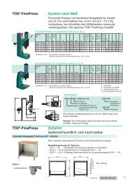
TOX®-Pneumohydraulic Unit Type KT
TOX®-Pneumohydraulic Unit Type KT
TOX®-Pneumohydraulic Unit Type KT

You also want an ePaper? Increase the reach of your titles
YUMPU automatically turns print PDFs into web optimized ePapers that Google loves.
2<br />
<strong>Type</strong> x = L or O<br />
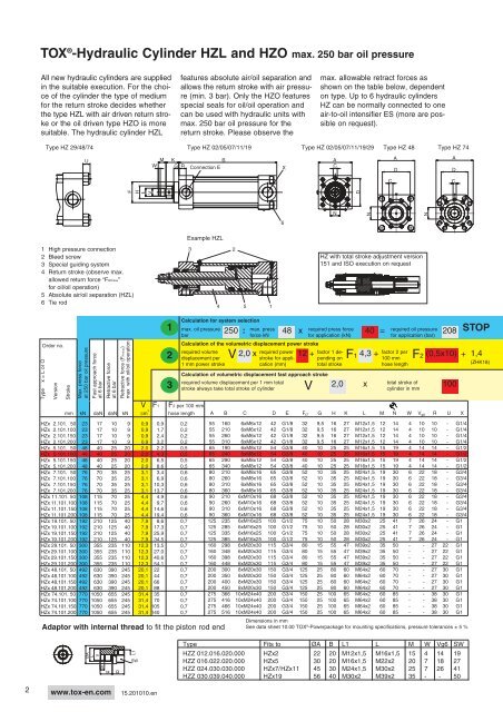
TOX ® -Hydraulic Cylinder HZL and HZO max. 250 bar oil pressure<br />
All new hydraulic cylinders are supplied<br />
in the suitable execution. For the choice<br />
of the cylinder the type of medium<br />
for the return stroke decides whether<br />
the type HZL with air driven return stroke<br />
or the oil driven type HZO is more<br />
suitable. The hydraulic cylinder HZL<br />
<strong>Type</strong> HZ 29/48/74 <strong>Type</strong> HZ 02/05/07/11/19<br />
Version<br />
Stroke<br />
U<br />
1 High pressure connection<br />
2 Bleed screw<br />
3 Special guiding system<br />
4 Return stroke (observe max.<br />
allowed return force “FRHmax”<br />
for oil/oil operation)<br />
5 Absolute air/oil separation (HZL)<br />
6 Tie rod<br />
Order no.<br />
Max. press force<br />
at 250 bar oil pressure<br />
Fast approach force<br />
at 6 bar<br />
Retractive force<br />
at 6 bar<br />
Retractive force (FRHmax)<br />
max with oil/oil operation<br />
W<br />
F<br />
H<br />
L<br />
V<br />
V F1 F2 per 100 mm<br />
mm kN daN daN kN cm 3<br />
hose length<br />
HZx 2.101. 50 23 17 10 9 0,9 0,9 0,2<br />
HZx 2.101.100 23 17 10 9 0,9 1,7 0,2<br />
HZx 2.101.150 23 17 10 9 0,9 2,4 0,2<br />
HZx 2.101.200 23 17 10 9 0,9 3,2 0,2<br />
HZx 5.101. 50 48 40 25 20 2,0 2,2 0,5<br />
HZx 5.101.100 48 40 25 20 2,0 4,3 0,5<br />
HZx 5.101.150 48 40 25 20 2,0 6,5 0,5<br />
HZx 5.101.200 48 40 25 20 2,0 8,6 0,5<br />
HZx 7.101. 50 76 70 35 25 3,1 3,4 0,6<br />
HZx 7.101.100 76 70 35 25 3,1 6,9 0,6<br />
HZx 7.101.150 76 70 35 25 3,1 10,3 0,6<br />
HZx 7.101.200 76 70 35 25 3,1 13,7 0,6<br />
HZx 11.101. 50 108 115 70 25 4,4 4,9 0,6<br />
HZx 11.101.100 108 115 70 25 4,4 9,7 0,6<br />
HZx 11.101.150 108 115 70 25 4,4 14,6 0,6<br />
HZx 11.101.200 108 115 70 25 4,4 19,4 0,6<br />
HZx 19.101. 50 192 210 125 40 7,9 8,6 0,7<br />
HZx 19.101.100 192 210 125 40 7,9 17,3 0,7<br />
HZx 19.101.150 192 210 125 40 7,9 25,9 0,7<br />
HZx 19.101.200 192 210 125 40 7,9 34,5 0,7<br />
HZx 29.101. 50 300 355 235 110 12,3 13,5 0,7<br />
HZx 29.101.100 300 355 235 110 12,3 27,0 0,7<br />
HZx 29.101.150 300 355 235 110 12,3 40,6 0,7<br />
HZx 29.101.200 300 355 235 110 12,3 54,1 0,7<br />
HZx 48.101. 50 492 630 390 245 20,1 22 0,7<br />
HZx 48.101.100 492 630 390 245 20,1 44 0,7<br />
HZx 48.101.150 492 630 390 245 20,1 66 0,7<br />
HZx 48.101.200 492 630 390 245 20,1 88 0,7<br />
HZx 74.101. 50 770 1050 655 245 31,4 35 0,7<br />
HZx 74.101.100 770 1050 655 245 31,4 70 0,7<br />
HZx 74.101.150 770 1050 655 245 31,4 105 0,7<br />
HZx 74.101.200 770 1050 655 245 31,4 140 0,7<br />
M K<br />
B A<br />
G R Connection E<br />
X<br />
C<br />
1<br />
2<br />
3<br />
Example HZL<br />
Adaptor with internal thread to fit the piston rod end<br />
ØA<br />
L<br />
V<br />
W<br />
M<br />
www.tox-en.com<br />
B<br />
L1<br />
SW<br />
15.201010.en<br />
features absolute air/oil separation and<br />
allows the return stroke with air pressure<br />
(min. 3 bar). Only the HZO features<br />
special seals for oil/oil operation and<br />
can be used with hydraulic units with<br />
max. 250 bar oil pressure for the<br />
return stroke. Please observe the<br />
3<br />
4<br />
required volume displacement per 1 mm total<br />
stroke always take total stroke of cylinder<br />
2<br />
5<br />
Calculation for system selection<br />
max. oil pressure<br />
bar<br />
250 max. press<br />
force kN<br />
for application (kN)<br />
Calculation of the volumetric displacement power stroke<br />
required volume<br />
displacement per V 2,0 x required power 12 + factor 1 de-<br />
stroke for applipending on F1<br />
1 mm power stroke<br />
cation (mm)<br />
total stroke<br />
1<br />
6<br />
N<br />
D<br />
N<br />
Typ <strong>Type</strong> HZ HZ 48 48 <strong>Type</strong> Typ HZ HZ 74 74<br />
A<br />
D<br />
C C<br />
HZ with total stroke adjustment version<br />
151 and ISO execution on request<br />
: 48 x required press force 40 = required oil pressure 208<br />
Calculation of volumetric displacement fast approach stroke<br />
V<br />
max. allowable retract forces as<br />
shown on the table below, dependent<br />
on type. Up to 6 hydraulic cylinders<br />
HZ can be normally connected to one<br />
air-to-oil intensifier ES (more are possible<br />
on request).<br />
<strong>Type</strong> HZ 02/05/07/11/19/29<br />
2,0<br />
4,3 +<br />
total stroke of<br />
cylinder in mm<br />
A B C D E F f7 G H K L M N W V g6 R U X<br />
Dimensions in mm<br />
See data sheet 10.00 TOX ® 55 160 6xM6x12 42 G1/8 32 9,5 16 27 M12x1,5 12 14 4 10 10 - G1/4<br />
55 210 6xM6x12 42 G1/8 32 9,5 16 27 M12x1,5 12 14 4 10 10 - G1/4<br />
55 260 6xM6x12 42 G1/8 32 9,5 16 27 M12x1,5 12 14 4 10 10 - G1/4<br />
55 310 6xM6x12 42 G1/8 32 9,5 16 27 M12x1,5 12 14 4 10 10 - G1/4<br />
65 190 6xM8x12 54 G3/8 40 10 25 25 M16x1,5 15 19 4 14 14 - G1/2<br />
65 240 6xM8x12 54 G3/8 40 10 25 25 M16x1,5 15 19 4 14 14 - G1/2<br />
65 290 6xM8x12 54 G3/8 40 10 25 25 M16x1,5 15 19 4 14 14 - G1/2<br />
65 340 6xM8x12 54 G3/8 40 10 25 25 M16x1,5 15 19 4 14 14 - G1/2<br />
80 210 6xM8x16 65 G3/8 52 10 35 25 M24x1,5 19 30 6 22 18 - G3/4<br />
80 260 6xM8x16 65 G3/8 52 10 35 25 M24x1,5 19 30 6 22 18 - G3/4<br />
80 310 6xM8x16 65 G3/8 52 10 35 25 M24x1,5 19 30 6 22 18 - G3/4<br />
80 360 6xM8x16 65 G3/8 52 10 35 25 M24x1,5 19 30 6 22 18 - G3/4<br />
90 210 6xM10x16 68 G3/8 52 10 35 25 M24x1,5 19 30 6 22 18 - G3/4<br />
90 260 6xM10x16 68 G3/8 52 10 35 25 M24x1,5 19 30 6 22 18 - G3/4<br />
90 310 6xM10x16 68 G3/8 52 10 35 25 M24x1,5 19 30 6 22 18 - G3/4<br />
90 360 6xM10x16 68 G3/8 52 10 35 25 M24x1,5 19 30 6 22 18 - G3/4<br />
125 235 6xM16x25 100 G1/2 75 10 50 28 M30x2 25 41 7 26 24 - G1<br />
125 285 6xM16x25 100 G1/2 75 10 50 28 M30x2 25 41 7 26 24 - G1<br />
125 335 6xM16x25 100 G1/2 75 10 50 28 M30x2 25 41 7 26 24 - G1<br />
125 385 6xM16x25 100 G1/2 75 10 50 28 M30x2 25 41 7 26 24 - G1<br />
160 298 6xM20x30 115 G3/4 80 15 55 47 M39x2 35 50 - - 27 22 G1<br />
160 348 6xM20x30 115 G3/4 80 15 55 47 M39x2 35 50 - - 27 22 G1<br />
160 398 6xM20x30 115 G3/4 80 15 55 47 M39x2 35 50 - - 27 22 G1<br />
160 448 6xM20x30 115 G3/4 80 15 55 47 M39x2 35 50 - - 27 22 G1<br />
200 300 8xM20x30 150 G3/4 125 25 80 60 M64x2 60 70 - - 27 30 G1<br />
200 350 8xM20x30 150 G3/4 125 25 80 60 M64x2 60 70 - - 27 30 G1<br />
200 400 8xM20x30 150 G3/4 125 25 80 60 M64x2 60 70 - - 27 30 G1<br />
200 450 8xM20x30 150 G3/4 125 25 80 60 M64x2 60 70 - - 27 30 G1<br />
275 366 10xM24x40 200 G3/4 150 25 100 65 M64x2 60 85 - - 38 30 G1<br />
275 416 10xM24x40 200 G3/4 150 25 100 65 M64x2 60 85 - - 38 30 G1<br />
275 466 10xM24x40 200 G3/4 150 25 100 65 M64x2 60 85 - - 38 30 G1<br />
275 516 10xM24x40 200 G3/4 150 25 100 65 M64x2 60 85 - - 38 30 G1<br />
-Powerpackage for mounting specifications, pressure tolerances ± 5 %<br />
x<br />
N<br />
for application (bar)<br />
factor 2 per<br />
100 mm<br />
hose length<br />
F2<br />
A<br />
D<br />
(0,5x10)<br />
<strong>Type</strong> Fits to ØA B L1 L M W Vg6 SW<br />
HZZ 012.016.020.000 HZx2 22 20 M12x1,5 M16x1,5 15 4 14 19<br />
HZZ 016.022.020.000 HZx5 30 20 M16x1,5 M22x2 20 7 18 27<br />
HZZ 024.030.030.000 HZx7/HZx11 45 30 M24x1,5 M30x2 25 7 26 41<br />
HZZ 030.039.040.000 HZx19 56 40 M30x2 M39x2 35 - - 50<br />
100<br />
STOP<br />
+ 1,4<br />
(ZHK18)