TOX®-Pneumohydraulic Unit Type KT
TOX®-Pneumohydraulic Unit Type KT
TOX®-Pneumohydraulic Unit Type KT

You also want an ePaper? Increase the reach of your titles
YUMPU automatically turns print PDFs into web optimized ePapers that Google loves.
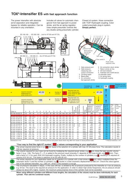
TOX ® -Intensifier ES with fast approach function<br />
The power intensifier with absolute<br />
air/oil separation and integrated<br />
bypass for reliable operation. Can be<br />
mounted in any orientation.<br />
=<br />
=<br />
1<br />
2<br />
3<br />
4<br />
ØF<br />
ZHK 018 1<br />
X<br />
ES 100.100 ... - ES 350.100 ... (not for AT100 and AT170)<br />
W<br />
8<br />
D<br />
2<br />
E<br />
3 4<br />
G<br />
required volumetric<br />
displacement for<br />
power stroke (cm 3 )<br />
9 5 6 7 11<br />
required volumetric<br />
displacement for fast<br />
approach stroke (cm 3 )<br />
10<br />
B V<br />
ES 300.12 ... - ES 350.12 ... (for AT100 and AT170)<br />
ZHK 042 1 2 3 4 9 5 6 7<br />
ØF<br />
D<br />
E G<br />
X W<br />
B<br />
Includes all valves for automatic changeover<br />
from fast approach to power<br />
stroke, and the air spring regulator.<br />
Uses simple pneumatic controls like<br />
any double acting pneumatic cylinder.<br />
V<br />
O<br />
O<br />
C<br />
C<br />
4<br />
40,52 x Number of<br />
metric displacement<br />
2<br />
= 81,04<br />
cylinders<br />
Required total volu-<br />
power stroke for application<br />
(cm 3 )<br />
Required total volu-<br />
x Number of<br />
metric displacement<br />
196 2<br />
= 392<br />
cylinders<br />
H±0,3<br />
A<br />
Y<br />
H±0,3<br />
A<br />
Y<br />
Order no. A B C D E F G H O V W X Y Connection<br />
fast approach stroke<br />
for application (cm 3 )<br />
Fast<br />
approach<br />
Connection<br />
Return stroke<br />
Closed oil system. Hose connection<br />
with TOX ® -Hydrosplit coupling. Color<br />
coded pneumatic plug-in system.<br />
Simply perfect.<br />
12 1 2<br />
High<br />
pressure hose<br />
Back pressure<br />
line for flow<br />
control X<br />
1 High pressure port<br />
2 High pressure<br />
measuring and<br />
control connection<br />
3 Oil filling nipple<br />
4 Bleed plate<br />
5 Air connection<br />
fast approach stroke<br />
Calculated oil<br />
pressure 1<br />
3 8 4 9 7 6 11<br />
6 Air connection return stroke<br />
7 Return stroke air line<br />
8 Oil level indicator<br />
9 Patented anti-overfill device<br />
10 Intensifier piston<br />
11 Air spring valve<br />
12 Hydrosplit coupling<br />
246 : 54 = 4,55<br />
Required air pressure<br />
for application<br />
(bar)<br />
Dimensions in mm *Caution: theoretical pressure and power values shown may differ from values on actual pressure table. ** Pressure tolerance ± 5%<br />
The actual required press force, e. g. 50 kN, leads to the selection of a cylinder with max. 81 kN press force. The calculation results in<br />
246 bar required oil pressure.<br />
The volume required for your case can be found by multiplying the required power stroke, e.g. 12 mm, times the type specific volume<br />
factor V (e.g. 1.96). The factor F1 + F2 is added to the previous result (whereby F2 depends on the hose length, e.g. 1000 mm). Then,<br />
add a factor of 1.5 for each ZHK 018 Hydrosplit coupling. Finally, multiply by the number of cylinders, e.g. 2 , resulting in a required oil<br />
volume of 81.04 cm3 . This leads to selection of an ES with 85 cm3 .<br />
The stroke required for your application leads you to selection of a cylinder with a total stroke of 100 mm, which multiplied times the<br />
volumetric factor V and the number of cylinders, e.g. 2, results in a total volumetric displacement of 392 cm3 . Check this value against<br />
that of the selected intensifier, e.g. 1300 cm3 “Your way to find the right <strong>KT</strong> system” = values corresponding to your application<br />
, which in this example is enough.<br />
The oil pressure calculated in step 1 , in this case 246 bar, is divided by the oil pressure produced by the intensifier at 1 bar air pressure,<br />
e.g. 54 bar. The result is the required air pressure for the application. In order to obtain high stroke frequencies, the air pressure should<br />
always be about 20% higher. Caution: the maximum pressure/press force of the cylinder must not be exceeded.<br />
When using different cylinders and different hose lengths, the calculation of the volume must be done individually for each<br />
cylinder. Then add the combined results.<br />
15.201010.en www.tox-en.com 5<br />
Connection<br />
High<br />
pressure<br />
5<br />
Volumetric<br />
displacement<br />
for<br />
fast app.<br />
stroke cm 3<br />
“OR” Valve<br />
Flow control X<br />
Power stroke<br />
sequence valve<br />
Volumetric<br />
displacement<br />
for<br />
power stroke<br />
cm3 Oil pressure<br />
at<br />
1 bar air<br />
pressure<br />
bar<br />
ES 100.100.022.70 110 551 64 9 15 90 22,5 85 265 110 234 max. 100 240 G1/2 G1/2 G3/4 360 22 57* 6 345**<br />
ES 160.100.085.64 170 731 86 9 15 95 22,5 85 330 130 303 max. 100 300 G3/4 G3/4 G3/4 1300 85 54* 6 328**<br />
ES 250.100.216.80 267 886 134,5 9 15 130 22,5 85 427 150 395 max. 100 340 G1 G1 G3/4 4600 216 66* 6 400**<br />
ES 300.100.381.62 324 867 167 14 20 130 92 100 484 150 379 max. 100 400 G1 G1 G3/4 6100 381 52* 6 316**<br />
ES 350.100.500.76 368 1075 189 14 20 145 92 100 528 150 450 max. 100 420 G1 G1 G3/4 10700 500 64* 6 388**<br />
ES 350.100.830.76 368 1457 189 14 20 145 92 100 528 150 709 max. 100 420 G1 G1 G3/4 15000 830 64* 6 388**<br />
ES 100.100.039.39 110 551 64 9 15 90 22,5 85 265 110 234 max. 100 240 G1/2 G1/2 G3/4 350 39 35* 10 355**<br />
ES 160.100.134.41 170 731 86 9 15 90 22,5 85 330 130 303 max. 100 300 G3/4 G3/4 G3/4 1300 134 36* 10 365**<br />
ES 250.100.395.43 267 886 134,5 9 15 130 22,5 85 427 150 395 max. 100 340 G1 G1 G3/4 4600 395 38* 10 385**<br />
ES 300.100.665.36 324 867 167 14 20 130 92 100 484 150 379 max. 100 400 G1 G1 G3/4 6000 665 33* 10 330**<br />
ES 350.100.844.45 368 1075 189 14 20 145 92 100 528 150 450 max. 100 420 G1 G1 G3/4 10600 844 41* 10 410**<br />
ES 350. 12.381.62 324 867 167 14 20 130 92 100 484 150 379 max. 205 400 G1 G1 SAE2” 6100 381 52* 6 316**<br />
ES 350. 12.500.76 368 1075 189 14 20 145 92 100 528 150 450 max. 205 420 G1 G1 SAE2” 10700 50 64* 6 388**<br />
ES 350. 12.830.76 368 1457 189 14 20 145 92 100 528 150 709 max. 205 420 G1 G1 SAE2” 15000 830 64* 6 388**<br />
ES 350. 12.844.45 368 1075 189 14 20 145 92 100 528 150 450 max. 205 420 G1 G1 SAE2” 10600 844 41* 10 410**<br />
Max.<br />
air<br />
pressure<br />
bar<br />
Max.<br />
oil pressure<br />
bar