186 PUENTE DE SERRERIA - FCC Construcción
186 PUENTE DE SERRERIA - FCC Construcción
186 PUENTE DE SERRERIA - FCC Construcción

Create successful ePaper yourself
Turn your PDF publications into a flip-book with our unique Google optimized e-Paper software.
Pont de l´Assut de l´Or<br />
(Puente de Serrería), Valencia<br />
L´Assut de l´Or Bridge (Serrería bridge), Valencia, Spain<br />
Luis Viñuela (1) y José Martínez Salcedo (2)<br />
Recibido | Received: 29-09-2009<br />
Aceptado | Accepted: 11-11--2009<br />
(1) Ingeniero de Caminos, <strong>FCC</strong> <strong>Construcción</strong>, S.A. (Madrid, España)<br />
(2) Ingeniero de Caminos, Servicio de Obras Especiales, <strong>FCC</strong> <strong>Construcción</strong>, S.A. (Madrid, España)<br />
Persona de contacto / Corresponding author: jmartinez@fcc.es<br />
Volumen 60, nº 254, 7-28 | octubre-diciembre 2009 | ISSN: 0439-5689<br />
HORMIGÓN Y ACERO | 7<br />
Resumen<br />
En este artículo se describe el proyecto y construcción del puente conocido como Puente de Serrería durante<br />
su construcción, y ahora Pont de l´Assut de l´Or, proyecto de Santiago Calatrava que se ubica en la Ciudad<br />
de las Artes y las Ciencias de Valencia. Como es habitual en las obras del mismo, une la originalidad del diseño<br />
arquitectónico con la singularidad estructural: un solo vano atirantado, sin vanos de compensación, con un<br />
pilono inclinado, de directriz curva, atirantado en su coronación.<br />
Palabras clave: Calatrava, Ciudad de las Artes, puente atirantado.<br />
Abstract<br />
In this article we describe the design and construction of the bridge now known as Pont de l´Assut de l´Or, but during<br />
its construction as Puente de la Serreria. It´s a design from Santiago Calatrava, located in Ciudad de las Artes y las<br />
Ciencias, Valencia, Spain. As in other works of the same author, original architectural design goes together with singular<br />
structural concepts: one single stayed span without back or side spans, a curved pylon stayed back only at its top.<br />
Keywords: Calatrava, Ciudad de las Artes, stayed bridge.<br />
* Page 85 of this issue contain an extensive English language summary of this article for inclusion in databases.<br />
Realizaciones y Proyectos
Realizaciones y Proyectos<br />
8 | HORMIGÓN Y ACERO<br />
1. INTRODUCCIÓN<br />
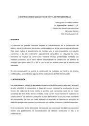
El puente conocido como Puente de Serrería durante su<br />
construcción, y ahora Pont de l´Assut de l´Or (Figura 1),<br />
es un proyecto de Santiago Calatrava que se ubica en la<br />
Ciudad de las Artes y las Ciencias de Valencia. Como es<br />
habitual en las obras de Calatrava, une la originalidad<br />
del diseño arquitectónico con la singularidad estructural:<br />
un solo vano atirantado, sin vanos de compensación,<br />
con un pilono inclinado, de directriz curva, atirantado<br />
en su coronación.<br />
2. <strong>DE</strong>SCRIPCIÓN GENERAL<br />
El puente forma parte de un diseño arquitectónicamente<br />
más amplio, con tramos de acceso por ambos extremos<br />
del mismo. En la Figura 2, aunque sea de forma esquemática,<br />
se observa la integración de todos estos elemen-<br />
Figura 1. Vistas generales del puente.<br />
Figure 1. General view of the bridge.<br />
1. INTRODUCTION<br />
Pont de l´Assut de l´Or (Puente de Serrería), Valencia<br />
The bridge known during construction as Serreria Bridge,<br />
and now as Pont de L´Assut de l´Or (Figure 1), is a project<br />
of Santiago Calatrava in the City of Arts and Sciences of<br />
Valencia. As usual in Calatrava´s works it has at the same<br />
time architectural originality and structural singularity: a<br />
single span, without back spans, with an leaning pylon of<br />
curved geometry, stayed at its top.<br />
2. GENERAL <strong>DE</strong>SCRIPTION<br />
Figura 2. Alzado de puente, vanos de acceso y cimentaciones.<br />
Figure 2. Front view of the bridge, approach spans and foundations.<br />
The bridge is part of a more general architectural design, with<br />
approach spans on both sides of it. In figure 2, although only<br />
an outline, we can see all these elements, though the approach<br />
spans aren’t considered in this article.<br />
The cable stayed bridge, of only one span, has the following<br />
elements (Figures 2 and 3):<br />
Volumen 60, nº 254, 7-28 | octubre-diciembre 2009 | ISSN: 0439-5689 L. Viñuela y J. Martínez
L´Assut de l´Or bridge (Serrería Bridge), Valencia<br />
tos, donde los vanos de acceso no son objeto del presente<br />
artículo.<br />
El puente atirantado, de un solo vano, está compuesto<br />
de los siguientes elementos (Figuras 2 y 3):<br />
• Tablero metálico de chapa ortótropa de 160 metros de<br />
luz, cuyo ancho varía entre 35.5 y 39.2 metros, este<br />
último en su intersección con el pilono.<br />
• Torre-Pilono metálico, de 125 metros de altura, inclinado,<br />
de directriz curva y sección metálica.<br />
• Cables de atirantamiento central del tablero. El<br />
número de tirantes es 29.<br />
• Tirantes de retenida que, en número de 4, atirantan el<br />
extremo del pilono al hormigón de un contrapeso,<br />
que se integra en uno de los vanos de acceso (ver<br />
Figura 2).<br />
Sus principales dimensiones, se señalan en la Figura 3.<br />
Funcionalmente este puente da servicio a dos calzadas<br />
con tres carriles de circulación cada una, un carril de circulación<br />
para un tranvía y un carril peatonal-bici que se<br />
sitúa en la zona central del tablero.<br />
3. ESQUEMA ESTRUCTURAL<br />
El conjunto tablero-pilono está empotrado entre sí,<br />
uniéndose a su vez con la base que es una gran pieza<br />
metálica que, a modo de pila, se empotra en la cimentación<br />
(Figuras 4 y 5).<br />
El tablero está apoyado y atirantado en el estribo Norte,<br />
opuesto al pilono, con dos barras articuladas tipo biela;<br />
Volumen 60, nº 254, 7-28 | octubre-diciembre 2009 | ISSN: 0439-5689<br />
Figura 3. Alzados.<br />
Figure 3. Elevations.<br />
HORMIGÓN Y ACERO | 9<br />
• Steel orthotropic deck with a span of 160 m. Its width<br />
changes between 35.5 and 39.2 m, this last value at the<br />
crossing with the pylon.<br />
• Steel pylon, with a height of 125m, leaning and with a<br />
curved geometry.<br />
• Main span cables. The number of stays is 29.<br />
• Back span stays, in a number of 4, they connects the top<br />
of the pylon to the concrete counterweight that forms part<br />
of one of the approach spans. (see Figure 2).<br />
The main dimensions are marked on figure 3.<br />
From a functional point of view, the bridge has two carriageways<br />
with three lanes each one, one additional lane for a<br />
tramway and another for pedestrian and cycle traffic, this last<br />
in the middle of the deck.<br />
3. STRUCTURAL LAYOUT<br />
The deck and the pylon are built in between them and also<br />
fixed on the base that is a great steel element, like a short pier<br />
that’s fixed to the foundation. (Figures 4 and 5).<br />
The deck is supported and anchored at the North abutment,<br />
opposite to the pylon, with two pinned links; no bearings to<br />
take positive reactions are used, instead these link bars can<br />
take tension or compression, and with a length of about 4 m<br />
can permit the relative horizontal movements between deck<br />
and abutment. In this way the difficulty of placing conventional<br />
bearings and at the same time anchoring is avoided,<br />
because when additionally the horizontal movements are significant<br />
the solution isn’t easy.<br />
The deck continues after the intersection with the pylon, 20<br />
m towards the nearest abutment (see Figure 5), the South<br />
L. Viñuela y J. Martínez<br />
Realizaciones y Proyectos
Realizaciones y Proyectos<br />
10 | HORMIGÓN Y ACERO<br />
Figura 4. Infografía del tablero, pilono y base: Vista inferior<br />
(Horta).<br />
Figure 4. Computer drawing of deck, pylon and pier:<br />
Bottom view (Horta)<br />
no se colocan apoyos que tomen las reacciones positivas,<br />
sino que se utilizan esas barras que trabajan a tracción<br />
o a compresión, y que con cuatro metros de altura<br />
permiten los grandes movimientos horizontales del<br />
tablero respecto al estribo. De esta forma se evita la<br />
complicación de colocar apoyos convencionales y a la<br />
vez atirantar, dado que cuando además los movimientos<br />
son importantes, no es fácil esa solución.<br />
El tablero continúa más allá de su intersección con el<br />
pilono, 20 metros hacia el estribo más cercano (ver<br />
Figura 5), estribo Sur, abriéndose en dos cajones independientes<br />
para salvar el ancho del pilono: está pequeña<br />
parte de puente es irrelevante a efectos estructurales.<br />
Sus apoyos en este estribo, sólo recogen reacciones<br />
positivas: se ajusta la reacción en montaje, para que así<br />
sea.<br />
El pilono inclinado está atirantado en cabeza a un contrapeso<br />
de hormigón, y tiene una directriz curva, correspondiente<br />
al antifunicular de cargas que le transmiten<br />
los cables de atirantamiento y los de retenida, en el estado<br />
de carga permanente. De esta forma el pilono, bajo<br />
estas cargas, tiene un trabajo prácticamente de compresión<br />
con momentos muy pequeños, aunque bajo las<br />
sobrecargas aparecerán momentos que se superponen a<br />
los axiles. Al tener el atirantamiento de retenida tanta<br />
longitud, y a causa del alargamiento por axil del mismo,<br />
éste no ejerce una función de apoyo rígido del extremo<br />
del pilono: de ahí la composición de su sección, que más<br />
adelante se describirá, en la que se busca aumentar el<br />
área de la misma, para reducir ese alargamiento.<br />
4. <strong>DE</strong>SCRIPCIÓN <strong>DE</strong> LOS DISTINTOS ELEMENTOS<br />
4.1. Cimentaciones<br />
La cimentación del pilono (Figuras 6 y 7) consiste en 20<br />
pilotes de diámetro 2 m. La longitud de los pilotes es de<br />
43 metros y se empotran 6 metros en unas gravas muy<br />
compactas que aparecen en profundidad, atravesando<br />
unos espesores potentes de arcillas y gravas mediana-<br />
Pont de l´Assut de l´Or (Puente de Serrería), Valencia<br />
Figura 5. Infografía del tablero, pilono y base: Vista superior<br />
(Horta).<br />
Figure 5. Computer drawing of deck, pylon and pier: Top view<br />
(Horta)<br />
abutment, opening into two box girders to avoid the width of<br />
the pylon: this small part of the bridge has no structural contribution.<br />
Its supports on the abutment, only take upwards<br />
reactions: the reaction is adjusted during the erection to be<br />
sure that this happens.<br />
The pylon is stayed on its top to a concrete counterweight,<br />
and has a curved axis, the funicular curve of the loads applied<br />
to it by the main span stays and the top back stays, under the<br />
permanent load condition. In this way the pylon, under these<br />
load conditions mainly subjected to axial compression with<br />
only small amounts of bending moments, though under live<br />
loads it does has to take moments in addition to the axial compression.<br />
As back stays are so long, their elongation due to<br />
axial tension, may reduce its effectiveness as rigid support of<br />
the top point of the pylon: that the reason of its section, that<br />
will be later described, in which an objective is an increase of<br />
area, to reduce this elongation.<br />
4. <strong>DE</strong>SCRIPTION OF THE DIFFERENT ELEMENTS<br />
4.1. Foundations<br />
The foundation of the pylon (Figures 6 and 7) has 20 piles of<br />
2 m diameter. The length of these piles is 43 meters and they<br />
get into dense gravels that are present at that depth 6 m,<br />
going through thick layers of clay and medium dense gravels.<br />
On top of the piles we have a pile cap of 19x 25 m and a variable<br />
depth up to 6 m in the middle. Even with this depth the<br />
pile cap had to be prestressed with 20 tendons of 42Ø0.6” due<br />
to its overhang.<br />
The counterweight of the back stays of the bridge (Figure 8<br />
and Figure 2) is integrated in the hollow abutment of south<br />
approach. The structure of this abutment has a frame of<br />
columns with a diameter 1.6 m in a layout of 9.0 x 10.4 m,<br />
that support a reinforced concrete slab of 0.5 m depth that<br />
takes the loads from the road traffic and the tramway. The<br />
four back stays get anchored on this structure by means of 10<br />
tendons of 31Ø0.6’’ in loops with a radius of 2 m. For taking<br />
the pull of the back stays the depth of the foundation slab is<br />
increased under its anchoring position, making up a concrete<br />
Volumen 60, nº 254, 7-28 | octubre-diciembre 2009 | ISSN: 0439-5689 L. Viñuela y J. Martínez
L´Assut de l´Or bridge (Serrería Bridge), Valencia<br />
Figura 6. Cimentación de pilono. Sección longitudinal<br />
Figure 6. Foundation of the pylon. Longitudinal section.<br />
mente compactas. En coronación de los pilotes se sitúa<br />
un encepado de 19x25 m de superficie y canto variable,<br />
llegando a ser de 6 m en las secciones intermedias. A<br />
pesar del canto del encepado, debido a los vuelos existentes<br />
en la cimentación, se postesó el encepado con 20<br />
tendones de 42Ø0.6”.<br />
El contrapeso de retenida del puente (Figura 8 y Figura<br />
2) está integrado en el estribo hueco de acceso sur. La<br />
estructura de este estribo está formada por un entramado<br />
de pilares de 1.6 m de diámetro dispuestos en una<br />
retícula de 9 m x 10.4 m, continuación del tablero del<br />
puente, que soportan una losa armada de 0.50 m de<br />
canto sobre la que circula el tráfico rodado y tranvía.<br />
Los cuatro cables de retenida se anclan a esta estructura<br />
mediante un sistema de pretensado formado por 10<br />
tendones 31Ø0.6’’ dispuestos en bucle con un radio de<br />
2 m. Para equilibrar el tiro de los cables de retenida se<br />
aumenta el canto de la losa de cimentación del estribo<br />
bajo su anclaje, generando un contrapeso de hormigón<br />
de 40 m x 22.5 m x 5 m. El conjunto del estribo descansa<br />
sobre un estrato de arcillas muy blandas susceptibles<br />
de importantes asientos de consolidación que haría colgar<br />
el contrapeso, del pilono. Para evitarlo, esa losa de<br />
contrapeso se apoya sobre 84 pilotes prefabricados de<br />
Volumen 60, nº 254, 7-28 | octubre-diciembre 2009 | ISSN: 0439-5689<br />
HORMIGÓN Y ACERO | 11<br />
counterweight of 40 m x 22.5 m x 5 m. The abutment as a<br />
whole elements lays on top of a layer of very soft clays that are<br />
prone to significant settlements, with these the counterweight<br />
would hang from the pylon. To avoid it, the slab is<br />
supported by 84 prefabricated concrete piles of 0.4x 0.4 m,<br />
with a layout of 3.25x3.25 m, that get into a layer of dense<br />
gravel about 15 m below.<br />
4.2. Deck<br />
Figura 8. Contrapeso de retenida.<br />
Figure 8. Counterweight of back stays.<br />
Figura 7. Cimentación de pilono. Sección transversal<br />
Figure 7. Foundation of the pylon, Transversal section<br />
The deck has a span of 160 m, if we consider the distance<br />
between the support on the furthest abutment and the axis of<br />
the pier though because its great dimension, it has a span of<br />
150 m from its face to the support on the abutment. The total<br />
length is 180 m (see Figure 3).<br />
The cross section of the deck, from the pier to the North abutment,<br />
is a trapezoidal box girder of constant depth and a cantilever<br />
on each side, all of them of steel (Figure 9).<br />
The steel used, in accordance with nomenclature of previous<br />
edition of EN10025 is S355J2G3 for thickness below 60mm<br />
and S355K2G3 when the thickness is greater.<br />
L. Viñuela y J. Martínez<br />
Realizaciones y Proyectos
Realizaciones y Proyectos<br />
12 | HORMIGÓN Y ACERO<br />
hormigón, de 0.4 m x 0.4 m de sección, dispuestos en<br />
retícula de 3.25 m x 3.25 m, y empotrados en un estrato<br />
de gravas densas a unos 15 m de profundidad.<br />
4.2. Tablero<br />
El tablero tiene una luz de 160 m, si se considera la distancia<br />
desde el apoyo en el estribo más alejado de la<br />
pila, al eje de la misma, aunque por la gran dimensión<br />
de la pila, tiene 150 m desde el borde de la misma hasta<br />
el apoyo en estribo. La longitud total es de 180 m (Ver<br />
Figura 3).<br />
La sección del tablero, desde pila al estribo Norte,<br />
opuesto, está formada por un cajón unicelular trapecial<br />
de canto constante y unas ménsulas a ambos lados,<br />
todos ellos metálicos (Figura 9).<br />
El acero que lo forma, es, con nomenclatura de la anterior<br />
versión de la norma EN 10025, S355J2G3 para espesores<br />
menores de 60 mm y S355K2G3 para espesores<br />
superiores a este.<br />
Las dimensiones generales de cajón y ménsula, a lo<br />
largo del tablero, se definen en la Figura 10.<br />
Las dimensiones del cajón (Figuras 10 y 11) son ligeramente<br />
variables, disminuyendo las mismas desde el<br />
pilono al estribo opuesto, Norte: canto entre 2.9 y 3.3 m,<br />
ancho inferior 4.8 a 8.4 m y ancho superior entre 5.8 m<br />
y 9.4 m. Las variaciones en el ancho superior e inferior<br />
son debidas a que el cajón se va abriendo al acercarse al<br />
pilono, para evitar la pérdida de ancho útil en su intersección<br />
con el mismo. Aunque bien es verdad que se<br />
podría haber dado un ancho uniforme a este cajón,<br />
coincidente con el máximo necesario, el diseño arquitectónico<br />
requería lo descrito.<br />
Su ala inferior es curva en su zona central y recta en los<br />
laterales y tiene un espesor tipo de 30 mm en la mayor<br />
parte del tablero, aunque llega a 50 mm en la zona de<br />
intersección con el pilono. Está rigidizada por perfiles<br />
en T, armados, con separación del orden de 1200 mm,<br />
que pasan a través de los diafragmas (Figura 11).<br />
Las almas tienen un espesor habitual de 22 mm, aunque<br />
alcanzan los 30 mm en zonas de estribo y encuentro con<br />
Figura 10. Sección transversal tipo.<br />
Figure 10. Typical cross section.<br />
Pont de l´Assut de l´Or (Puente de Serrería), Valencia<br />
Figura 9. Infografía de composición del tablero (Horta).<br />
Figure 9. Computer drawing of deck (Horta).<br />
The general dimensions of the box girder and the cantilevers,<br />
along the deck are defined on Figure 10.<br />
The dimensions of the box girder (Figures 10 and 11) are<br />
slightly variable, they reduce from the pylon towards the<br />
opposite abutment: the depth varies between 2.9 and 3.3 m,<br />
the bottom width between 4.8 and 8.4 m and the top width<br />
between 5.8 and 9.4 m. The changes in top and bottom width<br />
are due to the opening of the box girder as it approaches to the<br />
pylon, to avoid losing section in the crossing with it.<br />
Although a uniform cross section could have been given to<br />
this box girder, the biggest dimension, the architectural<br />
design required what has been described.<br />
The bottom flange is curved in the central part and straight<br />
on the laterals and has a thickness of 30 mm in nearly the<br />
whole deck, though it gets to 50 mm in the intersection with<br />
the pylon. It’s stiffened by welded T sections with an average<br />
spacing of 1200 mm, that go through the diaphragms (Figure<br />
11).<br />
The webs have a typical thickness of 22 mm, and get to 30<br />
mm near the abutments and the pylon and also have welded<br />
T stiffeners that go through the diaphragms.<br />
The top flange of the box girder is part of the orthotropic deck,<br />
though with a greater thickness of the plate due to its work as<br />
top flange of the box and because it’s subjected to local introduction<br />
of the forces from the stays. Its typical thickness is 22<br />
mm. This flange is stiffened by closed section stiffeners with<br />
a depth of 350 mm and 10 mm thick, with a spacing variable<br />
due to changing width of the flange, with a typical value of<br />
800 mm between axes. On top of the flange, over the plate, a<br />
small concrete slab is the pedestrian walkway: this is the rea-<br />
Volumen 60, nº 254, 7-28 | octubre-diciembre 2009 | ISSN: 0439-5689 L. Viñuela y J. Martínez
L´Assut de l´Or bridge (Serrería Bridge), Valencia<br />
el pilono. También llevan rigidización en T, que atraviesan<br />
los diafragmas.<br />
El ala superior del cajón, forma parte del tablero ortótropo,<br />
aunque con mayor espesor de chapa por su trabajo<br />
como ala superior del cajón, y por estar sometida a<br />
los esfuerzos concentrados de los tirantes. Su espesor<br />
habitual es de 22 mm. Esta ala está rigidizada por bulbos<br />
de chapa plegada de canto 350 y espesor 10 mm<br />
separados a distancias variables por el cambio de ancho<br />
de ala, y en la sección media a unos 800 mm entre ejes.<br />
Sobre el ala superior, con un recrecido de hormigón, se<br />
sitúa el paso peatonal: por ello, esta zona del cajón no<br />
tiene posibles problemas de fatiga en su chapa ortótropa.<br />
Este aspecto y sobre todo las fuertes cargas concentradas<br />
que introducen los cables en los diafragmas,<br />
llevó a diseñar los bulbos de esta zona, no continuos<br />
sino interrumpidos en los diafragmas para que estos no<br />
tuviesen aligeramientos, soldados a tope contra la<br />
chapa de diafragma, inspeccionando las soldaduras<br />
bulbos-diafragmas al 100% para evitar fisuración en la<br />
soldadura por el embridamiento que se produce, que<br />
dificulta la retracción de la soldadura.<br />
En esta misma ala superior, en su zona central, se sitúa<br />
un pequeño cajón de 600x450 mm, que es el que recibe,<br />
a través de un tubo donde se ancla el tirante, la carga<br />
concentrada de los tirantes (Figuras 12 y 13: en esta última<br />
se ha eliminado la chapa ortótropa de piso). La componente<br />
horizontal la transmitirá este cajón a la chapa<br />
superior del tablero o chapa ortótropa de piso, y la componente<br />
vertical, al diafragma correspondiente.<br />
Los diafragmas (Figuras 12 y 13), se sitúan cada 5<br />
metros que es la separación de los tirantes. Están situados<br />
en la vertical del punto de intersección del eje del<br />
tirante con el ala superior del cajón. Es una chapa de 20<br />
mm, con un paso central para paso de hombres y equi-<br />
Volumen 60, nº 254, 7-28 | octubre-diciembre 2009 | ISSN: 0439-5689<br />
Figura 11. Sección tipo del cajón central unicelular.<br />
Figure 11. Typical cross section of box girder.<br />
HORMIGÓN Y ACERO | 13<br />
son of why no fatigue problems can happen in this part of the<br />
box girder. What has been previously mentioned together<br />
with the need of taking the high forces from stays by the<br />
diaphragms, made us design closed stiffeners fitted between<br />
the diaphragms and not passing through them, so they didn’t<br />
have openings. The welds of the stiffener against the<br />
diaphragms were 100% inspected to avoid any cracking in<br />
the weld due to the restrained condition in which it takes<br />
place, that doesn’t allow the free shrinkage of the weld metal<br />
as it cools.<br />
In this top flange, in the middle, we have a small box section<br />
of 600x 450mm, which takes by means of a tube where the<br />
stays are anchored, the forces from the stays (Figure 12 and<br />
13: in this last one the plate of the orthotropic deck is omitted).<br />
The horizontal component of this force is taken by the box section<br />
to the top plate of the deck, orthotropic deck plate, and the<br />
vertical component by the diaphragm there positioned.<br />
The diaphragms (Figure 12 and 13), have a spacing of 5<br />
meters in correspondence with the spacing of stays. They are<br />
placed in the vertical of the crossing of the axis of the stay<br />
with the top flange of the box girder. They are made of a 20<br />
mm plate with a central opening for access for maintenance<br />
and for the equipment required for stressing, and two circular<br />
openings for equipment; the central opening is stiffened<br />
and the circular ones are reinforced by adding some plates<br />
From the pylon towards the south abutment the central box<br />
becomes, as already mentioned (see figures 4 and 5), two smaller<br />
box sections with similar typology to that of the single box<br />
girder (Figure 14). The spacing of closed stiffeners is also big,<br />
because its flange supports only the pedestrian walkway.<br />
On both sides of the central box girder we have a great constant<br />
cantilever of 14.2 m (Figure 15). It has a depth of 2.5 m<br />
L. Viñuela y J. Martínez<br />
Realizaciones y Proyectos
Realizaciones y Proyectos<br />
14 | HORMIGÓN Y ACERO<br />
pos de inspección y tesado, y dos pasos circulares para<br />
instalaciones; se rigidiza el paso central y se refuerzan<br />
con chapas adosadas, los circulares.<br />
Desde el pilono hasta el estribo Sur, el tablero se convierte,<br />
como ya se ha señalado (Ver Figuras 4 y 5), en<br />
dos pequeños cajones de tipología similar al cajón único<br />
(Figura 14). La separación de bulbos es también grande,<br />
por pertenecer su ala superior a la zona peatonal.<br />
De ambos lados del cajón central, salen unas grandes<br />
ménsulas de longitud de voladizo constante de 14.2 m<br />
(Figura 15). Tienen un canto, en su unión con el cajón<br />
central, de 2.5 m, que va variando hasta 0.7 m en el<br />
extremo de la ménsula, con un alma de espesor 15 mm<br />
en la zona más exterior y 20 mm, en la cercana al cajón.<br />
Su ala inferior, de espesor 30 mm, tiene un ancho variable<br />
de 400 a 800 mm. El ala superior es la chapa ortótropa,<br />
y dado que esta zona soportará el tráfico, se cuidaron<br />
al máximo los detalles que minimicen los riesgos de<br />
futuras fisuras de fatiga (ver [1]). La chapa de piso tiene<br />
un espesor de 14 mm, y los bulbos trapeciales que la<br />
rigidizan, formados con chapa de espesor 10 mm<br />
(excepto en la zona bajo el tranvía, que tienen espesor<br />
superior) tienen un canto de 350 mm, un ancho en su<br />
unión con la chapa de piso, de 300 mm, y una separación<br />
entre ejes de los mismos, de 630 mm. Quedan pues<br />
en la chapa de piso, unas luces de 300 y 330 mm.<br />
Respecto a los espesores de la chapa ortótropa necesarios<br />
para evitar fisuras por fatiga, se han endurecido<br />
Figura 12. Anclaje de tirantes en el cajón central.<br />
Figure 12. Anchorage of stays in the central box section.<br />
Pont de l´Assut de l´Or (Puente de Serrería), Valencia<br />
Figura 13. Infografía de detalle de anclaje de tirantes (Horta).<br />
Figure 13. Computer drawing. Anchorage<br />
of stays detail (Horta)<br />
in its connection to the box girder and 0.7m at its tip, with a<br />
web of 15 mm in the outer part and 20 mm near the box girder.<br />
Its bottom flange has a thickness of 30 mm, with a width<br />
that changes between 400 and 800mm. The top flange is the<br />
orthotropic deck, and as in this part it will have to support<br />
traffic, load detailing has to be cared for to minimize the risk<br />
of future fatigue cracks (see [1]). The deck plate thickness is<br />
14 mm, and the closed section stiffeners that stiffen it have a<br />
thickness of 10 mm (except in the part below the tramway<br />
where they have a bigger thickness) with a depth of 350 mm,<br />
their top width in connection with the deck plate is 300mm,<br />
Volumen 60, nº 254, 7-28 | octubre-diciembre 2009 | ISSN: 0439-5689 L. Viñuela y J. Martínez
L´Assut de l´Or bridge (Serrería Bridge), Valencia<br />
los requisitos de las recomendaciones de la parte de<br />
puentes metálicos del Eurocódigo 3: tradicionalmente,<br />
antes de los Eurocódigos, se pedían 12 mm para evitar<br />
las fisuras por fatiga, en la versión experimental (prenorma<br />
europea) del Eurocódigo [2], que se aplicó a este<br />
puente, se pedía un espesor mínimo de 14 mm, para<br />
espesores de pavimento entre 40 y 70 mm, y en la<br />
norma definitiva editada muy recientemente y aún no<br />
traducida por Aenor, EN 1993-2 :2006 [3], que anula la<br />
anterior, aumentan la recomendación de espesor de la<br />
chapa de piso a 16 mm, para el mismo caso de espesor<br />
de pavimento. En el caso que nos ocupa el pavimento<br />
tiene un espesor considerado en proyecto, entre 40 y 60<br />
mm.<br />
Los bulbos son continuos al paso por el alma de la<br />
ménsula, y el detalle de paso se efectúa con soldadura<br />
“todo alrededor” del bulbo (Figura 16), detalle admitido<br />
por el Eurocódigo. En [1], se explican más detalladamente<br />
los motivos por los que se considera preferible<br />
este tipo de paso frente a otros quizá más habituales<br />
en otros países: al no ser necesario rebordear la soldadura<br />
a través de huecos en las chapas, permite una<br />
mayor facilidad de construcción y mejor tolerancia a<br />
los defectos.<br />
Volumen 60, nº 254, 7-28 | octubre-diciembre 2009 | ISSN: 0439-5689<br />
Figura 14. Sección entre pilono y estribo sur.<br />
Figure 14. Cross section between the pylon and the South abutment<br />
Figura 15. Alzado de ménsula lateral.<br />
Figure 15. Front view of lateral cantilever.<br />
HORMIGÓN Y ACERO | 15<br />
and they have a spacing between axis of 630 mm. So we have<br />
spacing of supports for the deck plate of 300 and 330mm.<br />
About the minimum thickness of the deck plate of an orthotropic<br />
deck, needed to avoid fatigue cracking, the requirements of<br />
the recommendations of the part of Eurocode 3 devoted to steel<br />
bridges have got tougher: the common practice, before<br />
Eurocodes, a 12 mm plate was used to avoid fatigue cracking.<br />
In the experimental version (European prestandard) of the<br />
Eurocode [2], that was used in this bridge, 14 mm were<br />
required when the asphalt layer was between 40 and 70mm,<br />
and in the final version, just published and not yet translated<br />
by Aenor, EN 1993-2 :2006 [3], that supersedes previous ones<br />
the recommendation increases the thickness of the deck plate to<br />
16mm, for that thickness of asphalt. In our case the thickness<br />
of asphalt considered in the project was between 40 and 60mm.<br />
The closed sections stiffeners pass through the web of the cantilevers,<br />
and the detail is without cope holes and welded all<br />
around (Figure 16), as allowed by Eurocode. In reference [1],<br />
we can find a more detailed reasoning of why we prefer this<br />
type of solution instead of others that are perhaps more frequent<br />
in other countries: as no returns of the welds through<br />
the cope holes are needed, there are less possible origins for<br />
notches and the fabrication is less sensible.<br />
L. Viñuela y J. Martínez<br />
Realizaciones y Proyectos
Realizaciones y Proyectos<br />
16 | HORMIGÓN Y ACERO<br />
También se siguió el Eurocódigo en lo referente a los<br />
detalles de la unión de bulbos y a la soldadura de<br />
empalme de chapa de piso (Figura 16), disponiendo<br />
estos empalmes, cercanos al alma de las costillas.<br />
4.3. Pilono<br />
Está formado por una sección cajón metálica poligonal,<br />
de directriz curva, y de canto y ancho variable, según<br />
Figura 17, fuertemente inclinado, comenzando con un<br />
ángulo de 40º en su intersección con el tablero y llegando<br />
vertical en su coronación, donde le atacan los cables<br />
de la retenida. A medida que se sube en altura, van disminuyendo<br />
las dimensiones de la sección. Como ya se<br />
ha comentado, su directriz se adapta al antifunicular de<br />
las cargas de los tirantes y los cables de retenida en su<br />
coronación, de forma que ante las cargas permanentes,<br />
todo el pilono está trabajando fundamentalmente a<br />
compresión, con momentos muy reducidos.<br />
Los espesores de sus chapas, varían entre 40 y 80 mm, y<br />
la calidad del acero es S460 N, para espesores inferiores<br />
a 60 mm, y S460 NL para espesores superiores: dado<br />
que el acero de estas calidades no es de inmediato suministro,<br />
sino que se requiere su fabricación bajo pedido,<br />
se utilizó muy pequeña gama de espesores y se completó<br />
el área necesaria con los rigidizadores longitudinales<br />
en T, a base de chapas armadas: en este caso, por tanto,<br />
los rigidizadores muchas veces tienen como misión<br />
principal aportar área a la sección, más que colocarlos<br />
por necesidad de evitar la abolladura de las chapas<br />
exteriores, que tienen espesores muy fuertes y/o recoger<br />
las tensiones de curvatura. Las soldaduras longitudinales<br />
de la sección, que tiene numerosos quiebros,<br />
son de penetración parcial, ya que estructuralmente no<br />
es necesaria la penetración completa como suele suceder<br />
en casi todos los cajones, con lo que se produce una<br />
notable disminución de soldadura.<br />
Debido a la curvatura de sus alas (chapas por donde<br />
entran los cables, y las opuestas) es necesaria una fuer-<br />
Figura 16. Detalles tipo de chapa ortótropa.<br />
Figure 16. Typical details of orthotropic deck.<br />
Pont de l´Assut de l´Or (Puente de Serrería), Valencia<br />
Details of connection of the stiffeners and splices of deck plate<br />
(Figure 16) were also done in accordance with recommendations<br />
of Eurocode, and these connections were located near<br />
the web of the cantilevers.<br />
4.3. Pylon<br />
Figura 17. Sección tipo de pilono.<br />
Figure 17. Cross section of pylon.<br />
Its cross section is a polygonal box of curved axis, with variable<br />
height and width, in accordance with Figure 17, with an<br />
important inclination, that it starts with 40º at the intersection<br />
with the deck and gets to be vertical at the top, where the<br />
back stays are anchored. As we get up the dimensions of the<br />
cross section are reduced. As already mentioned, the axis is<br />
the funicular curve of the forces introduced by the main stays<br />
and the back stays, so under the permanent loading condition<br />
the whole pylon is under axial compression with only minimal<br />
bending moments.<br />
Volumen 60, nº 254, 7-28 | octubre-diciembre 2009 | ISSN: 0439-5689 L. Viñuela y J. Martínez
L´Assut de l´Or bridge (Serrería Bridge), Valencia<br />
Figura 19. Unión retenida-pilono.<br />
Figure 19. Connection between back stays and pylon.<br />
te rigidización transversal que recoja las cargas de desvío<br />
de las tensiones longitudinales, también formados<br />
por T de chapa armada, separados del orden de 3<br />
metros. En una de sus caras entran los cables de atirantamiento<br />
(Figura 18), con separación entre ellos variable<br />
Volumen 60, nº 254, 7-28 | octubre-diciembre 2009 | ISSN: 0439-5689<br />
Figura 18. Anclaje de tirante en pilono.<br />
Figure 18. Anchorage of cable in the pylon.<br />
HORMIGÓN Y ACERO | 17<br />
The thickness of plates are between 40 and 80 mm, and the<br />
quality of steel is S460 N, for thickness under 60 mm, and<br />
S460 NL for higher thickness: as material with this quality<br />
isn’t of immediate delivery, we only used a small range of<br />
plate thicknesses, and the required area was completed with<br />
longitudinal welded T stiffeners: in this case the stiffeners<br />
have as main task that of providing area, besides stiffening<br />
the surface plate, that are quite thick and also to take account<br />
of radial forces due to curvature of them. The longitudinal<br />
welds of the cross section, that has quite a lot of corners, are<br />
partial penetration as complete penetration isn’t needed from<br />
a structural point of view as it usually happens in compressed<br />
box sections, and in this way the volume of welding<br />
is clearly reduced.<br />
Due to the significant curvature of the flanges (plate through<br />
which the stays get in and the facing one) a strong transversal<br />
stiffening is needed to take the deviation forces. This stiffening<br />
with a spacing of about 3 m is also made of welded T<br />
sections. The stay cables (figure 18) get in through on of the<br />
faces, with a variable spacing as cables are parallel and the<br />
pylon has a changing slope, the transference of the forces of<br />
the cables to the cross section of the pylon is managed in a<br />
similar way as done in the deck (Figure 12 and 13): a tube is<br />
used for anchoring the cable. The component perpendicular<br />
to the axis is transmitted trough the transverse frame and<br />
the tangential component to the axis by means of a small<br />
welded box section connected to the surface plate of the<br />
pylon.<br />
On the top of the pylon the back stays are anchored (Figure<br />
19). This detail can’t be seen, as an architectural piece is<br />
placed over it.<br />
L. Viñuela y J. Martínez<br />
Realizaciones y Proyectos
Realizaciones y Proyectos<br />
18 | HORMIGÓN Y ACERO<br />
debido a que los cables son paralelos entre sí, y la torre<br />
es de directriz curva e inclinada: la transmisión de la<br />
tensión de los cables al pilono, se efectúa con un detalle<br />
igual al del tablero (Figuras 12 y 13): un tubo metálico<br />
recoge toda la tracción del tirante y transmite su componente<br />
perpendicular a la directriz del pilono, al<br />
marco transversal y su componente según la directriz, a<br />
un pequeño cajón de chapa armada, soldado al ala del<br />
pilono.<br />
En su extremo superior se anclan los cables de la retenida<br />
(Figura 19). Este detalle no queda visto, ya que se<br />
colocan unas chapas en coronación de carácter arquitectónico.<br />
Para el cálculo en segundo orden del pilono, se consideraron<br />
las imperfecciones fuera del plano de los tirantes,<br />
y en el plano de los tirantes. En el plano de los tirantes,<br />
se consideraron los dos primeros modos de pandeo: al<br />
ser de sección variable y curva su directriz, si se considerase<br />
solamente un modo de pandeo, existirían secciones<br />
en las que no se amplificarían los momentos. En el<br />
caso del pilono al tener con las cargas permanentes<br />
momentos muy pequeños en un cálculo en primer<br />
orden, es importante la influencia de las imperfecciones<br />
en segundo orden que producirán flexiones procedentes<br />
del axil, y considerar las tensiones de esas flexiones.<br />
4.4. Base<br />
Figura 20. Sección longitudinal del nudo Tablero-Pilono-Base.<br />
Figure 20. Longitudinal section of Deck-Pylon-Pier connection.<br />
Es la gran pieza metálica (Figuras 20 y 21) que integrada<br />
con el nudo pilono-tablero (Figuras 4 y 5), lleva los<br />
esfuerzos a cimentación. La dificultad de esta pieza proviene<br />
de las secciones con formas complejas, que acometen<br />
a ella: el cajón del tablero, con su ala inferior<br />
curva, y el pilono con sección muy poligonal. Las chapas<br />
que lo forman son chapas de 60 y 80 mm, rigidiza-<br />
Pont de l´Assut de l´Or (Puente de Serrería), Valencia<br />
In the second order calculations of the pylon, imperfections in<br />
the plane of the cables and out of the cables were allowed for.<br />
In the plane of the stays the two first modes were considered:<br />
as it’s a variable section if we only considered one mode there<br />
would be sections with small or even no additional moments.<br />
As the pylon under the permanent loading condition has very<br />
small bending moments, it’s quite important that the imperfections<br />
induce moments that can be then increased by second<br />
order effects.<br />
4.4. Base /Pier<br />
It is a great steel element (figures 20 and 21) that together<br />
with the connection between deck and pylon (Figures 4 and<br />
5), transfers the forces to the foundation. The main difficulty<br />
of this piece comes from the geometry of the cross sections of<br />
the elements that join in it, the box girder of the deck, with a<br />
curved bottom flange, and the pylon with a polygonal cross<br />
section. Its plates have thickness of 60 and 80 mm, heavily<br />
stiffened, all in steel S460NL. This great element is fixed to<br />
the foundation by means of 172 bars of 47mm and 950<br />
N/mm2 yield stress covered with Densoplast to avoid adherence<br />
with the surrounding concrete during stressing. The<br />
force is anchored by an end plate. They prestressing force is<br />
1050 kN. A final architectural shape is given with additional<br />
non structural plates.<br />
The total weight of the steel structure of the elements<br />
described, deck, pylon and pier is about 5600 T.<br />
4.5. Deck Stays<br />
Figura 21. Base.<br />
Figure 21. Pier.<br />
The bridge has 29 stays with the harp system, and angle to<br />
the horizontal of 26º. The cable system is BBR HiAm Cona<br />
from BBR-PTE (Spain), that was delivered and erected them.<br />
Each strand of 0.6” has its wires galvanized and wax protec-<br />
Volumen 60, nº 254, 7-28 | octubre-diciembre 2009 | ISSN: 0439-5689 L. Viñuela y J. Martínez
L´Assut de l´Or bridge (Serrería Bridge), Valencia<br />
das, en calidad S460NL. Esta gran pieza, se ancla a la<br />
cimentación, con 172 barras MK4 de 47 mm de diámetro,<br />
de límite elástico 950 N/mm2, recubiertas de<br />
Densoplast para evitar la adherencia con el hormigón, y<br />
con una chapa en su extremo, para poderlas tesar a 1050<br />
kN. La forma arquitectónica final se le dio con unas chapas<br />
adicionales.<br />
El peso total de los tres elementos metálicos descritos,<br />
tablero, pilono y base, es de 5600 ton, aproximadamente<br />
4.5. Atirantado<br />
El puente tiene 29 tirantes, situados en arpa, con una<br />
inclinación de 26º respecto a la horizontal. El sistema es<br />
BBR HiAm Cona de la empresa BBR-PTE (España), que<br />
también los instaló. Cada cordón de 0.6” tiene sus alambres<br />
galvanizados, y está protegido con cera en una<br />
vaina coextruida de HDPE (polietieleno alta densidad).<br />
Los anclajes de los tirantes, son aptos para un rango de<br />
tensiones de 300 MPa, y han sido homologados según<br />
[8]. Los anclajes activos se diseñaron para un ajuste<br />
entre 30 mm (tesado) y -70 mm (destesado).<br />
Los 6 tirantes más cortos (tirantes 1 a 6) están compuestos<br />
por 31 unidades de 0.6”, los tirantes 7 a 20, 61Ø0.6”,<br />
el 21, 55Ø0.6”, el 22, 49Ø0.6”, el 23, 43Ø0.6”, y los tirantes<br />
24 a 29, los más largos, 31Ø0.6”. La vaina exterior es<br />
de HDPE de color de acabado blanco, con doble hélice<br />
exterior para el fenómeno de vibraciones “rain-wind”.<br />
En cuanto al diámetro exterior la idea inicial era, por<br />
motivos estéticos, que todas tuviesen el mismo diámetro.<br />
No obstante, por causas aerodinámicas que más<br />
adelante se explican no fue así, aunque son sensiblemente<br />
iguales: Los tirantes 1 a 6 tienen una vaina interior<br />
de HDPE negro de Ø180 mm y una vaina exterior<br />
de Ø225 mm; Los tirantes 7 a 23 una vaina Ø225 mm,<br />
y los más largos y alejados del campo visual, tirantes 24<br />
a 29, su vaina es Ø180 mm.<br />
El anclaje activo se sitúa en el tablero. En los anclajes de<br />
los tirantes sensibles a vibraciones, 7 a 29, se colocan<br />
amortiguadores en el anclaje del tablero, que hacen<br />
también la función de centrador que reduce las tensiones<br />
en el anclaje por las variaciones en las curvaturas de<br />
los cables, colocando centrador de neopreno en el anclaje<br />
del pilono. En los tirantes 1 a 6, los más cortos, se<br />
coloca únicamente centrador de neopreno tanto en el<br />
anclaje del tablero como en el del pilono.<br />
4.6. Retenida de pilono<br />
La retenida, o atirantamiento del extremo del pilono, lo<br />
forman 4 grandes elementos tubulares, paralelos en la<br />
vista en alzado del puente, separados 1.9 metros, y que,<br />
por motivos aerodinámicos, se abren ligeramente en la<br />
vista longitudinal, partiendo de 2 m en coronación, a 6<br />
m en cimentación (ver Figura 3).<br />
Volumen 60, nº 254, 7-28 | octubre-diciembre 2009 | ISSN: 0439-5689<br />
HORMIGÓN Y ACERO | 19<br />
ted in a coextruded sheath of high density polyethylene. The<br />
anchorages of the cables have an effective category of 300MPa<br />
and have been tested / accepted in accordance with [8].The<br />
active anchorage provides and adjustment of 30mm for<br />
stressing increase and -70 mm for stressing decrease.<br />
The 6 shorter stays (stays 1 to 6) have 31 strands of 0.6”,<br />
stays from 7 to 20 have 61 strands, number 21 has 55Ø0.6”,<br />
number 22 has 49Ø0.6”, number 23 has 43Ø0.6”, and stays<br />
24 to 29, the longest have 31Ø0.6”. The common pipe is<br />
HDPE of white colour with double helical ribs against raininduced<br />
vibrations. For aesthetic reasons the idea was to have<br />
only single size on pipe for all stays. But due to aerodynamic<br />
reasons that will be later detailed it was not possible, though<br />
they are quite similar: stays 1 to 6 have and inside pipe of<br />
Ø180 mm and an outside one of Ø225 mm; stays 7 to 23 have<br />
a pipe of Ø225 mm, and the longest and furthest from sight,<br />
stays 24 t0 29 have a pipe of Ø180 mm.<br />
The active anchorage is at deck level. In the anchorage of<br />
stays sensible to vibrations, 7 to 29, dampers are provided in<br />
the deck anchorage, they also are used as guide deviators for<br />
reducing the bending stresses in the anchorage position due<br />
to angle changes of the stay. In the shortest stays 1 to 6, the<br />
damper isn’t needed and only guide deviators are provided in<br />
both deck and pylon anchorages.<br />
4.6. Back stays of the pylon<br />
The back stays of the top of the pylon is provided by 4 big<br />
tubular elements, parallel in a side view, with a spacing of 1.9<br />
m, and that due to aerodynamic reasons are slightly sloped in<br />
a front view, with a spacing that starts in 2 m at the top and<br />
ends in 6 m at the foundation level (see Figure 3).<br />
The length of these back stays between the pylon anchorage<br />
and the foundation one is 115 m, and the active anchorage is<br />
at the top of the pylon.<br />
Each of the four stays has a prestressing tendon of 85Ø0.6”,<br />
individually sheathed strands, the same as those of the stays,<br />
with the BBR HiAm Cona system from BBR-PTE, and a<br />
structural tube of 508 mm and a thickness of 36mm in S460<br />
NL. The reason for this combination isn’t only resistance, but<br />
mainly the need to provide them with axial stiffness, the elastic<br />
elongation of the stay should be as small as possible: in<br />
this way the bending moments that could be induced on the<br />
deck and the pylon by this elongation are reduced.<br />
Due to their erection sequence and as no windows could be<br />
provided on the tubular section, to avoid fatigue sensible<br />
welding details in a high strength material, it was very difficult<br />
to place elements that could assure a separation between<br />
the prestressing strands and the tubular section so they<br />
would move as a single body against vibrations. Another condition<br />
was that strands should be replaceable, so finally each<br />
stand was placed in an individual smooth HDPE sheath, and<br />
the space between them and the steel tube was filled with<br />
cement grout.<br />
L. Viñuela y J. Martínez<br />
Realizaciones y Proyectos
Realizaciones y Proyectos<br />
20 | HORMIGÓN Y ACERO<br />
La longitud entre el anclaje en el extremo del pilono y el<br />
anclaje en el contrapeso de hormigón es de 115 metros.<br />
El anclaje activo se sitúa en el extremo del pilono.<br />
Cada uno de estos cuatro tirantes está compuesto por<br />
unos cordones de pretensado, 85 unidades de 0.6” autoprotegidos,<br />
igual que los de los tirantes, con el sistema<br />
BBR HiAm Cona de la empresa BBR-PTE, y un tubo<br />
exterior de 508 mm de diámetro y 36 mm de espesor de<br />
acero S460 NL. El motivo de esta composición, no es<br />
solo por la resistencia de estos tirantes, sino por dotarles<br />
de rigidez de modo que el alargamiento elástico de<br />
los mismos sea lo más pequeño posible: así se consigue<br />
reducir los momentos que podrían aparecer en el pilono<br />
y en el tablero, debido al alargamiento elástico de<br />
este sistema.<br />
Debido al sistema constructivo y por motivos resistentes,<br />
dado que no se podían dejar ventanas en los tubos<br />
metálicos para evitar detalles sensibles a la fatiga en los<br />
mismos, por su elevado límite elástico, era muy complicado<br />
colocar separadores entre los cordones de pretensado<br />
y el tubo exterior, para que formasen un único ele-<br />
Figura 22. Esquemas del sistema constructivo.<br />
Figure 22. Erection procedure plan.<br />
Pont de l´Assut de l´Or (Puente de Serrería), Valencia<br />
The steel tube was provided with a helical steel rib as a measure<br />
against rain-induced vibrations, and near the bottom<br />
anchorage, the passive one, a friction damper was installed in<br />
each stay. Guide deviators, are provided at the top and bottom<br />
anchorages.<br />
5. ERECTION PROCEDURE<br />
The erection procedure is illustrated in Figure 22.<br />
The construction works start with the erection of the pier,<br />
then proceeds with the deck, and when the erection of the deck<br />
is well on its way erection the pylon starts. The deck hasn’t<br />
any camber but the pylon does.<br />
The pier, due to the thickness of its plates that would result in<br />
too heavy units was taken to site in several parts and then<br />
welded in situ. In Figure 23 we can see the connection joint<br />
between the pier and the pylon with the two box girders of the<br />
deck near the south abutment.<br />
In the deck itself, first the central box girder is erected, it was<br />
taken to site due to transport reasons in two segments, when<br />
Volumen 60, nº 254, 7-28 | octubre-diciembre 2009 | ISSN: 0439-5689 L. Viñuela y J. Martínez
L´Assut de l´Or bridge (Serrería Bridge), Valencia<br />
mento estructural frente a las vibraciones. Como, por<br />
otra parte, se buscaba la posibilidad de sustitución de<br />
cada cordón, se enfundó cada uno de ellos en una vaina<br />
de HDPE lisa, y se inyectó el espacio entre estas vainas<br />
y el tubo metálico, con mortero de cemento.<br />
Al tubo exterior metálico se le adosó una hélice metálica<br />
para evitar vibraciones por el fenómeno “wind-rain”.<br />
Cercano al anclaje inferior, pasivo, se coloca un amortiguador<br />
de fricción a cada tirante, y se dispone también<br />
de centrador de neopreno. En el anclaje superior en el<br />
pilono, solo se dispone de centrador.<br />
5. SISTEMA CONSTRUCTIVO<br />
El esquema general es el señalado en la Figura 22.<br />
La construcción comienza por el montaje de la gran<br />
base metálica, se sigue con el tablero y, cuando está sensiblemente<br />
avanzado el tablero, se comienza la construcción<br />
del pilono. El tablero no tiene contraflechas de<br />
ejecución, pero sí las tiene el pilono.<br />
La base, por el fuerte espesor de sus chapas que producían<br />
elementos muy pesados, se transportó en piezas a<br />
obra, para soldarlas in situ. En la Figura 23 se observa<br />
el nudo de unión de esta base con el pilono y los dos<br />
cajones del tablero de la zona cercana al estribo Sur.<br />
En cuanto al tablero, se monta en primer lugar el cajón<br />
central, que va partido longitudinalmente para su<br />
transporte, y una vez terminado este cajón, se montan<br />
las partes laterales en ménsula: en la Figura 24, se observa<br />
las fases de formación del cajón central y de las ménsulas.<br />
Todas las uniones son soldadas. Se posiciona de<br />
forma convencional sobre apeos, separados 20 metros;<br />
en este caso por su poca altura sobre el terreno, parece<br />
el montaje más adecuado. Solo se apea de forma permanente<br />
hasta el tesado de tirantes, la sección central en<br />
cajón, mientras que los apeos de las ménsulas son provisionales.<br />
Una vez sensiblemente avanzado el montaje del tablero,<br />
se comienza el montaje del pilono. El montaje se<br />
efectúa por dovelas (Figura 25 y 26), montadas con grúa<br />
sobre orugas Liebherr LR 1750 de capacidad máxima de<br />
750 toneladas. Esta grúa es capaz de montar las últimas<br />
dovelas, de peso 100 toneladas, hasta el extremo del<br />
pilono, situado a 125 metros sobre el suelo. Las dovelas<br />
se atornillan con el tramo ya montado, mediante una<br />
unión frontal con tornillos (ver Figura 25). Una vez<br />
comprobada la geometría, se suelda a tope la chapa<br />
exterior de la sección con su correspondiente de la<br />
dovela inferior, mientras que la continuidad de los rigidizadores<br />
se consigue con las mismas uniones frontales<br />
atornilladas, sin soldar.<br />
El pilono no era capaz de soportar su peso propio sin<br />
atirantamiento al tablero, por aparecer flexiones no<br />
admisibles. Por ello se colocan tres cables provisionales<br />
Volumen 60, nº 254, 7-28 | octubre-diciembre 2009 | ISSN: 0439-5689<br />
HORMIGÓN Y ACERO | 21<br />
Figura 23. Unión de pilono, tablero y base.<br />
Figure 23. Connection of deck, pier and pylon.<br />
Figura 24. Montaje de tablero y comienzo de pilono.<br />
Figure 24. Erection of deck and first stage of pylon.<br />
completed the erection proceeds with the cantilevers: on<br />
Figure 24, we can see the stages of erection of the central box<br />
girder and the cantilevers. All connections are welded.<br />
Segments are positioned with conventional shores spaced<br />
about 20 m; in this case as the height over the ground is small<br />
it seems the easiest procedure. Only the central box will be<br />
shored until stays are stressed, the shores of the cantilevers<br />
are only provisional.<br />
Once a significant part of the deck has been erected, the erection<br />
of the pylon begins. The erection procedure made by segments<br />
used a Liebherr LR 1750 crane with a maximum lift<br />
L. Viñuela y J. Martínez<br />
Realizaciones y Proyectos
Realizaciones y Proyectos<br />
22 | HORMIGÓN Y ACERO<br />
Figura 25. Dovela de pilono.<br />
Figure 25. Pylon erection unit.<br />
de atirantamiento a medida que avanza su construcción<br />
en altura, cables que en su momento se sustituirán por<br />
los definitivos. Esta situación se observa en la Figura 27.<br />
Una vez finalizada la construcción del pilono, se procede<br />
a colocar los tirantes definitivos que atirantan el tablero y<br />
a montar los tubos metálicos del atirantamiento de retenida.<br />
Estos últimos, se montan de arriba abajo con grúa<br />
(Figura 28) y, dado que no son paralelos, es necesario<br />
arriostrarlos provisionalmente, y posicionarlos correctamente<br />
para efectuar la soldadura a tope entre tramos, en<br />
altura, como se muestra en la Figura 29.<br />
Los tubos metálicos, no se anclan al contrapeso, en esta<br />
fase. Una vez terminado su montaje, se colocan los cordones<br />
interiores de 0.6”, enfilándolos por el extremo<br />
superior de los tubos, en la coronación del pilono. A<br />
medida que se va avanzando en el montaje y tesado de<br />
los cables de atirantamiento del tablero, se van tesando,<br />
en cuatro fases, los cordones de los tirantes de los cables<br />
de la retenida, con 4 gatos multifilares actuando simultáneamente<br />
en los cuatro anclajes. Hasta este momento<br />
el tubo metálico exterior de esos tirantes, no ejerce ninguna<br />
función estructural: toda la función de retenida la<br />
efectúan los cables de pretensado.<br />
Una vez montados todos los cables de atirantamiento,<br />
se realiza el último tesado a los cordones de la retenida,<br />
hasta 10700 kN por retenida y se conecta el tubo<br />
metálico al contrapeso. Se suelta, entonces, desde el<br />
anclaje activo situado en la coronación del pilono,<br />
parte de la carga que tenían los cordones, carga que se<br />
transfiere como tracción a los tubos metálicos, y se<br />
anclan definitivamente los cordones y los tubos. De<br />
esta forma el estado final resistente de los componentes<br />
de la retenida, cordones y tubos, es el mismo que si<br />
Pont de l´Assut de l´Or (Puente de Serrería), Valencia<br />
Figura 26. Montaje de dovela de pilono.<br />
Figure 26. Erection of pylon unit<br />
Figura 27. Situación de montaje<br />
con los tres tirantes provisionales.<br />
Figure 27. Erection stage with three provisional stays.<br />
capacity of 750 t. This crane could put into place the last erection<br />
units, with a weight of 110 t, at the tip of the pylon,<br />
about 125 m over the ground. The units were bolt connected<br />
with the already erected pylon by means of end plates (see<br />
Figure 25). Once the geometry was adjusted and checked, the<br />
outer surface plate was welded, full penetration, while the<br />
continuity of the stiffeners was achieved with the frontal bolted<br />
connections without welding.<br />
The pylon couldn’t take its selfweight without been stayed<br />
against the deck, the resulting bending moments weren’t<br />
allowable. That’s why three provisional stays were arranged<br />
Volumen 60, nº 254, 7-28 | octubre-diciembre 2009 | ISSN: 0439-5689 L. Viñuela y J. Martínez
L´Assut de l´Or bridge (Serrería Bridge), Valencia<br />
Figura 28. Montaje de tubos de retenida.<br />
Figure 28. Erection of back stay steel tubes.<br />
Figura 30. Anclaje retenida.<br />
Figure 30. Back stay anchorage.<br />
hubiesen estado trabajando juntos frente a las cargas<br />
de tracción: 8600 kN al tubo estructural y 2100 kN que<br />
quedan en los cables, para cada tirante. Por último, se<br />
inyecta de lechada de cemento el espacio entre los<br />
tubos en los que alojan los cordones, de forma individual,<br />
y el tubo metálico.<br />
Volumen 60, nº 254, 7-28 | octubre-diciembre 2009 | ISSN: 0439-5689<br />
HORMIGÓN Y ACERO | 23<br />
Figura 29. Unión para posicionado y soldadura de<br />
tubos de retenida.<br />
Figure 29. Connection for geometrical reference prior to welding<br />
of back stay tubes.<br />
as the erection proceeded with increased height. These cables<br />
will be replaced by the final ones during their sequence. This<br />
stage can be observed in Figure 27.<br />
When the construction of the pylon is completed, the erection<br />
procedure continues with the cables of the deck and with the<br />
erection of the steel tubes of the back stays. The erection of<br />
these tubes proceeds from the top to the bottom (Figure 28),<br />
and as they aren’t vertical, they need to be provided with provisional<br />
bracing, and they also have to be well aligned for<br />
welding between them took place in situ at considerable<br />
height, as can be seen in Figure 29.<br />
The steel tubes aren’t connected to the counterweight at this<br />
stage. Once their erection is completed, the prestressing tendons<br />
are placed inside them from the top of the pylon. As the<br />
erection sequence of the deck stays is finished the tendons of<br />
these back stay cables will be stressed in four stages by means<br />
of a strand by strand stressing. During all this time the steel<br />
tubes of these back stays have no structural role: the prestressing<br />
cables take the whole force.<br />
When the erection and stressing of all the deck stays has taken<br />
place, a last prestressing of the cables is done, up to 10700 kN<br />
per each of them, and the steel tube is connected to the counterweight.<br />
Then by means of four jacks, from the top of the<br />
pylon where active anchor heads are, some of the force of the<br />
cables is released, this force is transferred to the steel tubes.<br />
This way the final distribution of forces between the compo-<br />
L. Viñuela y J. Martínez<br />
Realizaciones y Proyectos
Realizaciones y Proyectos<br />
24 | HORMIGÓN Y ACERO<br />
Figura 31. Anclaje retenida en cámara de contrapeso.<br />
Figure 31. Back stay anchorage in the counterweight chamber.<br />
Con estas actuaciones se da por finalizado el proceso de<br />
puesta en carga de tirantes y retenida (Figura 32)<br />
6. ASPECTOS AERODINÁMICOS EN TIRANTES<br />
En este puente había dos aspectos que estudiar al respecto<br />
de la estabilidad aerodinámica de los tirantes y de<br />
la retenida: por una parte el debido a vibraciones por<br />
viento y lluvia que, aunque habitual en todos los tirantes<br />
de puentes, aquí se complicaba ya que se prefería,<br />
por motivos estéticos, que todas las vainas de los tirantes<br />
tuviesen el mismo diámetro, y por otra, se tenía el<br />
problema de la proximidad entre sí, de los tubos de la<br />
retenida (cilindros) que quedaban alineados frente al<br />
viento, situación que puede producir inestabilidad<br />
aerodinámica. Mientras la primera no es divergente, es<br />
decir que puede producir mucha amplitud de vibración<br />
que causará fatiga en el anclaje, pero no rotura en su<br />
primeras vibraciones, la segunda puede llegar a ser<br />
divergente, por autoalimentarse la vibración, y es por<br />
tanto más peligrosa.<br />
El análisis teórico del fenómeno más condicionante en<br />
las vibraciones de tirantes por viento y lluvia, conocido<br />
como “rain-wind induced vibrations” aún continúa.<br />
Los dos métodos prácticos para controlarlo están claramente<br />
establecidos: la textura superficial y un número<br />
de Scruton adecuado: en este puente, los tirantes del<br />
tablero tienen una doble hélice en su vaina, mientras<br />
que en la retenida, en el tubo exterior metálico, se dispone<br />
una hélice soldada al mismo, con lo que se les<br />
dota de la textura superficial.<br />
En el caso de vaina lisa se considera preciso, siguiendo<br />
el criterio de Irwin [4], un número de Scruton de 125,<br />
mientras que dotando de textura superficial a la vaina,<br />
como la doble hélice, es suficiente con la mitad ≈ 62 (el<br />
Pont de l´Assut de l´Or (Puente de Serrería), Valencia<br />
Figura 32. Tirantes y retenida ya tesados.<br />
Figure 32. Deck stays and back stays already stressed.<br />
nents of the back stays, steel tubes and prestressing tendons<br />
is the same as the would have had if they had been in placed<br />
together from the beginning: 8600 kN in the steel tube and<br />
2100 kN in the prestressing steel of each back stay. Finally,<br />
the gap between the tube and the individual sheaths of each<br />
strand of the tendon is injected with cement grout.<br />
With these operations the sequence of stressing of stays and<br />
back stays can be considered complete. (Figure 32)<br />
6. SOME REMARKS ON AERODYNAMIC BEHAVIOUR<br />
OF STAYS<br />
In this bridge there were two subjects related to the aerodynamic<br />
behaviour of the stays, deck and back stays, that had to<br />
be studied in detail: rain–induced vibrations though frequent<br />
in stays of bridges here had the additional restrain of the aesthetical<br />
objective of having all the pipes of the same diameter,<br />
and also the potential problem of the small spacing of the back<br />
stay tubes, that is prone to aerodynamic instability. The first<br />
on the problems isn’t divergent, that means that the amplitude<br />
of displacements is self limiting and though it will cause<br />
accumulation of fatigue, won’t break the cable immediately,<br />
on the other side galloping can be divergent, it’s a self excited<br />
vibration that can be unstable, and for that reason very<br />
dangerous.<br />
The theoretical analysis of the most important mechanism of<br />
vibrations for cable stays, the rain-induced vibrations, is still<br />
under research. But the two practical ways of controlling it<br />
are quiet well established: surface texture and a suitable<br />
Scruton number: in this bridge the deck stays are provided<br />
with a double helical rib on the pipe, and the back stay has<br />
also on its outside tube a welded helical rib to provide this<br />
surface texture.<br />
With smooth pipes in accordance with Irwin [4] criteria, a<br />
Scruton number of 125 is required, and when we have a cable<br />
Volumen 60, nº 254, 7-28 | octubre-diciembre 2009 | ISSN: 0439-5689 L. Viñuela y J. Martínez
L´Assut de l´Or bridge (Serrería Bridge), Valencia<br />
número de Scruton, es un parámetro adimensional particularmente<br />
útil en el análisis de la susceptibilidad<br />
frente a las vibraciones inducidas por flujos). Haciendo<br />
uso de la definición utilizada por el Eurocódigo (en ocasiones<br />
se utiliza una definición diferente, que equivale<br />
a dividir la formulación aquí indicada por 4π ) este<br />
número es:<br />
donde: δ s decremento logarítmico.<br />
ζ relativo, respecto del crítico<br />
ρ a densidad del aire: 1.25 kg/m 3<br />
m masa por unidad de longitud<br />
φ es el diámetro de la vaina<br />
Como ejemplo, se considera uno de los cables largos, el<br />
nº 24 de 31Ø 0.6”:<br />
l= 220 metros m=44 kg/m.<br />
El amortiguamiento intrínseco de un tirante de cables<br />
paralelos puede considerarse, como mínimo y del lado<br />
de la seguridad, δ s ≈ 0.6%, aunque un valor más realista<br />
sería 0.9% (ver [5] y [6]). Por otra parte el máximo<br />
amortiguamiento que se puede conseguir disponiendo<br />
un amortiguador, depende de la distancia del mismo al<br />
anclaje del tirante, y viene dado por:<br />
donde:<br />
s m m<br />
Sc = ⋅ ⋅<br />
=<br />
⋅<br />
⋅ ⋅ ⋅<br />
2 δ 4 π ζ<br />
2 2<br />
ρ φ<br />
ρ ⋅φ<br />
a a<br />
δ s , max = π (l d / l)<br />
l d distancia del amortiguador al anclaje<br />
l longitud del cable<br />
Aún con el amortiguador más eficaz unido al cable, y<br />
suponiendo que está conectado a una estructura rígida (lo<br />
que no es el caso, porque se sitúa en el interior de un tubo<br />
metálico con cierta flexibilidad), no se puede superar este<br />
valor del amortiguamiento. En el caso señalado, l d estaba<br />
limitado a 3.1 m por condicionantes arquitectónicos, dado<br />
que se pretendía que el tubo que aloja el amortiguador y<br />
sobresale del tablero, no tuviese mucha longitud: por consiguiente<br />
para este cable se puede conseguir un amortiguamiento<br />
máximo, δ s, max =4.4%.<br />
Con la vaina de φ=180mm, y sin amortiguador adicional<br />
se obtendría Sc=13
Realizaciones y Proyectos<br />
26 | HORMIGÓN Y ACERO<br />
Figura 33. Croquis de amortiguador.<br />
Figure 33. Sketch of damper.<br />
Conviene destacar la gran incidencia del diámetro de la<br />
vaina: si se quiere hacerla del mismo diámetro que la de<br />
los otros tirantes tipo, φ=225mm , el número de Scruton se<br />
reduce a 55 aún con el máximo amortiguamiento posible,<br />
que no es admisible ni con textura superficial. Esta es la<br />
razón por lo que las vainas de los cables largos de 31Ø0.6”<br />
no tienen el mismo diámetro del resto.<br />
El amortiguamiento que suplemente el intrínseco del<br />
tirante, se consigue situando un amortiguador de fricción<br />
(BBR Square Damper, Figuras 33 y 34), con el que<br />
se consigue un amortiguamiento adicional al intrínseco<br />
del 3.8%, mayor del necesario, lo que aporta un adicional<br />
coeficiente de seguridad. Finalmente, se pudo<br />
aumentar algo más la distancia entre la cabeza de anclaje<br />
del tirante y el eje del amortiguador, a 3.6 metros, lo<br />
que mejora la solución. En el caso de los tirantes de retenida,<br />
se sitúan los amortiguadores a 6.5 metros del<br />
anclaje de los cordones en el contrapeso.<br />
Disponiendo amortiguadores en el anclaje en el pilono,<br />
además del colocado en el anclaje inferior, podría duplicarse<br />
la capacidad de amortiguamiento que se puede<br />
lograr, pero es conveniente que estos amortiguadores<br />
sean lo más accesibles posible para su mantenimiento.<br />
En el caso de los “tirantes” de retenida, con tubo exterior<br />
metálico de diámetro 508 mm, se plantean sin duda estos<br />
mismos problemas, y se han dado las mismas soluciones:<br />
centradores, textura superficial, y amortiguadores en el<br />
anclaje inferior. Hay, sin embargo, otro problema adicional,<br />
dado que la separación entre los cuatro tubos que<br />
configuran la retenida es pequeña en relación a su diámetro:<br />
el fenómeno de vibración de un cilindro “tapado”<br />
frente al viento por otro próximo, no conectados, a causa<br />
de los torbellinos que se desprenden del que está en primera<br />
posición frente al flujo de viento, se conoce como<br />
galope de estela o galope de interferencia (“wake galloping”<br />
o “interference galloping”).<br />
Se trata de un fenómeno frecuente por ejemplo en los<br />
intercambiadores de calor, o en los tirantes dobles y<br />
próximos en puentes y, una vez que aparece, el fenóme-<br />
Pont de l´Assut de l´Or (Puente de Serrería), Valencia<br />
Figura 34. Amortiguador ya montado.<br />
Figura 34. Dumper on site.<br />
The additional damping to supplement the inherent damping<br />
of the cable is provided with a friction damper (BBR Square<br />
Damper, Figures 33 y 34), with it we can get an additional<br />
damping of 3.8%, more than needed, so we have a safety margin.<br />
Finally, the distance for placing the damper could be<br />
increased to 3.6 m, with a clear improvement of the solution.<br />
In the back stays, the dampers are placed at 6.5 m from the<br />
counterweight anchorage.<br />
Of course, if we place dampers on the other end of the cable,<br />
on the pylon, besides those of the deck we can get the double<br />
of additional damping, but a good access is needed for maintenance.<br />
In the back stays, with an outside diameter of 508 mm, we<br />
have without doubt the same problems, and the same solutions<br />
have been provided: guide deviators, surface texture and<br />
dampers in bottom anchorage. Anyhow it has one additional<br />
problem, as the spacing between the tubes of the back stay is<br />
small relative to their diameter: interference galloping, a self<br />
excited oscillation which may occur when two cylinders are<br />
arranged together, the flow pattern altered by the leading<br />
cylinder induces alternating forces in the downstream cylinder.<br />
Figura 35. Galope de interferencia (Figura de Ref. [7]).<br />
Figure 35. Interference galloping (Figure from reference [7]).<br />
Volumen 60, nº 254, 7-28 | octubre-diciembre 2009 | ISSN: 0439-5689 L. Viñuela y J. Martínez
L´Assut de l´Or bridge (Serrería Bridge), Valencia<br />
no puede ser sensiblemente divergente, por lo que debe<br />
evitarse alcanzar las velocidades criticas correspondientes<br />
al mismo. En cualquier caso, esta velocidad crítica<br />
se incrementa con la raiz cuadrada del número de<br />
Scruton. En la figura adjunta, Figura 35, procedente de<br />
[7], se visualiza cuando se produce este fenómeno en un<br />
tubo separado X/d e Y/d de otro, siendo d, el diámetro<br />
de los tubos: las líneas continuas son las trayectorias del<br />
tubo excitado, al que hace sombra el situado en el origen<br />
del diagrama. Se observa la máxima excitación para<br />
una separación entre centros de tubos entre 1.5d y 3.5d.<br />
(aunque en [5] se señala entre 3d y 4d).<br />
Para evitar este problema la separación mínima de los<br />
tubos de retenida es de 3.8 φ ≈ 4.0 φ . Adicionalmente se<br />
efectuaron ensayos en túnel de viento, para confirmar<br />
estos valores.<br />
REFERENCIAS<br />
[1] VIÑUELA, L., MARTÍNEZ SALCEDO, J., Proyecto y<br />
construcción de puentes metálicos y mixtos. Madrid: APTA,<br />
2009.<br />
[2] ENV 1993-2 :1997, European Prestandard Eurocode 3 -<br />
Part 2: Steel bridges.<br />
[3] EN 1993-2 :2006, Eurocode 3 - Design of steel structures<br />
- Part 2: Steel bridges.<br />
[4] “Wind-Induced Vibration of Stay Cables: Summary of<br />
FHWA Study”, Report No. FHWA-HRT-05-083. 2007.<br />
[5] “Cable stays – Recommandations of French interministerial<br />
commission on prestressing”. SETRA. 2002.<br />
[6] EN 1991-1-4: 2005. Eurocode 1: Actions on structures -<br />
Part 1-4: General actions - Wind actions.<br />
[7] NAUDASCHER, E., Rockwell, D., Flow Induced<br />
vibrations. Mineola, NY: Dover Pubns. 1994.<br />
[8] “Acceptance of stay cable systems using prestressing steels”.<br />
FIB Recommendation, Bulletin 30.<br />
[9] CASTAÑO, G., MARCHESI, I. “El puente del Azud<br />
del oro, en Valencia”. Cauce 2000. 2009, nº 146.<br />
Volumen 60, nº 254, 7-28 | octubre-diciembre 2009 | ISSN: 0439-5689<br />
HORMIGÓN Y ACERO | 27<br />
It’s a quite common phenomenon in heat exchangers, transmission<br />
lines and groups of cables in bridges, and once it<br />
starts the amplitude increase very quickly and can be divergent,<br />
that’s the reason why the critical wind velocity associated<br />
with it shouldn’t be exceeded. In any case the critical<br />
wind speed is also related to the Scruton number, it increases<br />
with the square root of it. In the following figure, Figure 35,<br />
taken from [7], we can see the loops described by a downstream<br />
cylinder as function of the relative position, X/d and<br />
Y/d, to the upstream one that placed in the origin. As can be<br />
seen the maximum excitation can be expected for a spacing of<br />
tubes in the range of 1.5 to 3.5 diameters (though in [5] the<br />
range is between 3 and 4 d).<br />
To avoid this problem the final minimum spacing of the back<br />
stay cables is 3.8φ ≈ 4.0φ. To confirm the solution wind tunnel<br />
test were done.<br />
REFERENCES<br />
[1] LUIS VIÑUELA y JOSÉ MARTÍNEZ SALCEDO.<br />
Proyecto y construcción de puentes metálicos y mixtos.<br />
APTA. 2009.<br />
[2] ENV 1993-2 :1997. European Prestandard Eurocode 3 -<br />
Part 2: Steel bridges.<br />
[3] EN 1993-2 :2006. Eurocode 3 - Design of steel structures<br />
- Part 2: Steel bridges.<br />
[4] “Wind-Induced Vibration of Stay Cables: Summary of<br />
FHWA Study”. Report No. FHWA-HRT-05-083. 2007.<br />
[5] “Cable stays – Recommendations of French interministerial<br />
commission on prestressing”. SETRA. 2002.<br />
[6] EN 1991-1-4: 2005. Eurocode 1: Actions on structures -<br />
Part 1-4: General actions - Wind actions.<br />
[7] NAUDASCHER. Flow Induced vibrations. Dover<br />
Pubns. 1994.<br />
[8] “Acceptance of stay cable systems using prestressing<br />
steels”. FIB Recommendation, Bulletin 30.<br />
[9] GUILLERMO CASTAÑO, IGNACIO MARCHESI.<br />
“El puente del Azud del oro, en Valencia”. Cauce 2000. 2009,<br />
nº 146.<br />
L. Viñuela y J. Martínez<br />
Realizaciones y Proyectos
Realizaciones y Proyectos<br />
28 | HORMIGÓN Y ACERO<br />
RELACIÓN <strong>DE</strong> PARTICIPANTES / LIST OF PARTICIPANTS<br />
• Promotor / Owner: C.A.C., S.A. - Generalitat Valenciana<br />
Pont de l´Assut de l´Or (Puente de Serrería), Valencia<br />
• Autor del proyecto y Director de la Obra / Architectural and structural design: Santiago Calatrava<br />
• Dirección de obra / Work’s Direction: Manuel Alcaide, Santiago Calatrava, S.A.<br />
• Dirección de obra (Dirección Técnica) / Technical Direction: Mario Rando, Santiago Calatrava, S.A.<br />
• Empresas constructoras / General contractor: UTE <strong>FCC</strong> <strong>Construcción</strong> S.A. – Pavasal<br />
• Gerente UTE / Civil engineer, Manager UTE: Guillermo Castaño, <strong>FCC</strong> <strong>Construcción</strong>, S.A.<br />
• Jefe de Obra/Jefe de Producción / Site managers: Ignacio Marchesi, Pavasal / Javier Ruipérez, <strong>FCC</strong> <strong>Construcción</strong><br />
• Servicio Obras Especiales de <strong>FCC</strong> <strong>Construcción</strong> / Technical assistence Servicio Obras Especiales de <strong>FCC</strong><br />
<strong>Construcción</strong>: José Martínez Salcedo; Ignacio Pita; Santiago del Río; José Enrique Muñoz.<br />
• Servicios Técnicos y Delegación Valencia / Technical assistence: <strong>FCC</strong> <strong>Construcción</strong><br />
• Estructura metálica, fabricación y montaje / Steel workshop: HORTA-COSLADA S.A.<br />
• Sistema de atirantado y montaje del mismo / Staying and prestressing system: BBR-PTE S.A.<br />
Volumen 60, nº 254, 7-28 | octubre-diciembre 2009 | ISSN: 0439-5689 L. Viñuela y J. Martínez