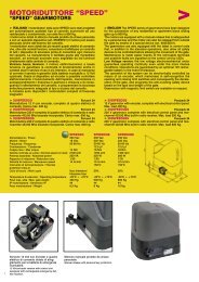
automations for gates sistema de automatización para portones ...
automations for gates sistema de automatización para portones ...
automations for gates sistema de automatización para portones ...

Create successful ePaper yourself
Turn your PDF publications into a flip-book with our unique Google optimized e-Paper software.
MODELS IN THE P200BENC<br />
MODELOS DE LA SERIE P200BENC<br />
Pull the terminal board out of its housing, as shown in<br />
Fig. A and observe how the wires are connected in or<strong>de</strong>r<br />
as shown in Fig. B:<br />
Wires of the photodio<strong>de</strong> enco<strong>de</strong>r card: white, brown, blue (0.5 mm² cross section);<br />
Motor phase wires: black, red (2.5 mm 2 cross section);<br />
The enco<strong>de</strong>r’s signal wires are to be connected to the MEC20 card connectors in the following way: brown - terminal 21,<br />
blue - terminal 22, white 1st motor - terminal 23, white 2nd motor - terminal 24.Connect the black and red wires of the 1 st<br />
motor to terminals 7 and 8 and to terminals 9 and 10 those of the 2nd motor. Check that the required maneuver<br />
corresponds to an opening input; to the contrary, reverse the position of the black-red wires.It is essential that the cross<br />
section of the wires must be i<strong>de</strong>ntical <strong>for</strong> connecting to the command card.<br />
Extraiga el tablero <strong>de</strong> bornes <strong>de</strong> su alojamiento, como muestra la figura A y observe con atención el or<strong>de</strong>n en el cual<br />
están conectados los cables, como muestra la figura B:<br />
Cables <strong>de</strong> la tarjeta encó<strong>de</strong>r fotodiodo: blanco, marrón y azul (secc. 0,5 mm²);<br />
Cables <strong>de</strong> la fase <strong>de</strong>l motor: negro y rojo (secc. 2,5 mm²);<br />
Los cables <strong>de</strong> señal <strong>de</strong>l encó<strong>de</strong>r se conectan a los conectores <strong>de</strong> la tarjeta MEC20 <strong>de</strong> la siguiente manera: marrón – borne 21,<br />
azul - borne 22, blanco 1er. motor - borne 23, blanco 2do. motor - borne 24.Conecte los cables negro y rojo <strong>de</strong>l 1er. motor a los<br />
bornes 7-8 y los <strong>de</strong>l 2do. motor a los bornes 9-10. Controle que a un input <strong>de</strong> apertura corresponda la maniobra <strong>de</strong>seada; en<br />
caso contrario invierta la posición <strong>de</strong> los cables negro y rojo.Para las conexiones a la tarjeta <strong>de</strong> comando, use únicamente<br />
cables con la misma sección.<br />
MODELS IN THE P2000 SERIES<br />
MODELOS DE LA SERIE P2000<br />
1) Connect up to the terminal of Fig. A with a wire whose cross section should at least be equal to 1.5 mm², checking motor<br />
rotation direction and remembering that:<br />
The yellow-green wire is the earth wire<br />
Blue is the common wire<br />
Black is the phase wire<br />
And brown is the phase wire.<br />
2) Connect the capacitor provi<strong>de</strong>d in <strong>para</strong>llel with the motor’s two phases in proximity of the electronic control card. Only use<br />
units equipped with an electric friction.<br />
1) Conectarse al borne <strong>de</strong> la Fig. 18 con cables que tengan una sección <strong>de</strong> al menos 1.5 mm², comprobando el sentido <strong>de</strong><br />
rotación <strong>de</strong>l motor, recordando que:<br />
Cable amarillo-ver<strong>de</strong> : tierra<br />
Cable azul : común<br />
Cable negro : fase<br />
Cable marrón : fase<br />
2) Cerca <strong>de</strong> la placa electrónica, conectar el con<strong>de</strong>nsador en equipamiento, en <strong>para</strong>lelo a las 2 fases <strong>de</strong>l motor. Utilizar<br />
exclusivamente centralitas dotadas <strong>de</strong> embrague eléctrico.