automations for gates sistema de automatización para portones ...
automations for gates sistema de automatización para portones ...
automations for gates sistema de automatización para portones ...

You also want an ePaper? Increase the reach of your titles
YUMPU automatically turns print PDFs into web optimized ePapers that Google loves.
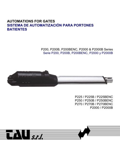
AUTOMATIONS FOR GATES<br />
SISTEMA DE AUTOMATIZACIÓN PARA PORTONES<br />
BATIENTES<br />
P200, P200B, P200BENC, P2000 & P2000B Series<br />
Serie P200, P200B, P200BENC, P2000 y P2000B<br />
P225 / P225B / P225BENC<br />
P250 / P250B / P250BENC<br />
P270 / P270B / P270BENC<br />
P2000 / P2000B
The manufacturer reserves the right to modify or improve them without prior notice. Any inaccuracies or errors found in<br />
this manual will be corrected in the next edition. When opening the packing please check that the product is in excellent<br />
condition. Do not let children play anywhere there may be a suffocation hazard. Please recycle materials in compliance<br />
with current regulations.<br />
La empresa fabricante se reserva el <strong>de</strong>recho a aportar modificaciones o mejoras en el producto sin aviso previo. Posibles<br />
errores o imprecisiones que se <strong>de</strong>tecten en este manual se corregirán en el próximo. Cuando abra el embalaje,<br />
compruebe la integridad <strong>de</strong>l producto. No <strong>de</strong>je que los niños jueguen en zonas don<strong>de</strong> exista peligro <strong>de</strong> ahogarse.<br />
Reciclar los materiales según las normativas vigentes<br />
A<br />
P225 - P225B - P225BENC 788 mm<br />
P250 - P250B - P250BENC 940 mm<br />
P270 - P270B - P270BENC 1030 mm<br />
TECHNICAL FEATURES OF THE P200 SERIES<br />
P225 P250 P270 P2000B P2000<br />
Power 230 VAC 230 VAC 230 VAC 230 VAC/12 VDC<br />
Frequency 50-60 Hz 50-60 Hz 50-60 Hz 50-60 Hz<br />
Absorbed current 1.4 A 1.4 A 1.4 A 1.6 A 1.0 A<br />
Absorbed power 300 W 300 W 300 W 60 W 340 W<br />
Motor speed 900 rpm 900 rpm 900 rpm 1200 rpm 900 rpm<br />
Max gate length 2.0 m 4.0 m 5.0 m 2.0 m 2.0 m<br />
Useful travel 32 cm 40 cm 50 cm 30 cm 30 cm<br />
Operating temperature -20°C to 60°C -20°C to 60°C -20°C to 60°C -20°C to 60°C -20°C to 60°C<br />
Thermal protection trips at 138°C 138°C 138°C<br />
Weight 7.8 kg 8.1 kg 10.4 kg 7 Kg. 7 Kg.<br />
Axial thrust 220 Kg 220 Kg 220 Kg 170 Kg. 220 Kg.<br />
Motor IP 13 13<br />
Working Cycle 100% 23%<br />
* These technical data are simply indicative.<br />
CARACTERISTICAS TECNICAS DE LA SERIE P200<br />
P225 P250 P270 P2000B P2000<br />
Alimentación 230 VAC 230 VAC 230 VAC 230 VAC/12 VDC 230 VAC<br />
Frecuencia 50/60 Hz 50/60 Hz 50/60 Hz 50-60 Hz<br />
Corriente Absorbida 1.4 A 1.4 A 1.4 A 1.6 A 1.0 A<br />
Potencia Absorbida 300 W 300 W 300 W 60 W 340 W<br />
Velocidad Motor 900 r.p.m. 900 r.p.m 900 r.p.m. 1200 rpm 900 rpm<br />
Longitud Máxima Hoja Puerta 2.0 m 4.0 m 5.0 m 2.0 m 2.0 m<br />
Carrera útil 32 cm 40 cm 50 cm 30 cm 30 cm<br />
Temperatura <strong>de</strong> Trabajo -20°C ÷ 60°C -20°C ÷ 60°C -20°C ÷ 60°C -20°C to 60°C -20°C to 60°C<br />
Activación <strong>de</strong>l Termo-Protector 138°C 138°C 138°C<br />
Peso 7.8 kg 8.1 kg 10.4 kg 7 Kg. 7 Kg.<br />
Empuje Axial. 220 Kg 220 Kg 220 Kg 170 Kg. 220 Kg.<br />
Motor IP 13 13<br />
Working Cycle 100% 23%<br />
* Estos datos son únicamente indicativos.
INSTALLATION MATERIAL<br />
MATERIALES PARA LA INSTALACIÓN<br />
1) Art. P-2250SP190 : Small galvanized bracket<br />
2) Art. M-V400008035 : M8 x 35 galvanized screw<br />
3) Art. -- : P200, P200B or P200BENC series actuator<br />
4) Art. P-2250SG190 : Large galvanized bracket<br />
5) Art. P-700PA1 : Angular galvanized bracket<br />
6) Art. M-V300000125 : 12.5 µF cylindrical capacitor<br />
1) Art. P-225OSP190 : brida pequeña galvanizada<br />
2) Art. M-V400008035 : tornillo galvanizado M8 x 35<br />
3) Art. -- : operador serie P200, P200B o P200BENC<br />
4) Art. P-2250SG190 : brida gran<strong>de</strong> galvanizada<br />
5) Art. P-700PA1 : brida angular galvanizada<br />
6) Art. M-V300000125 : con<strong>de</strong>nsador cilíndrico 12.5 µF (sólo <strong>para</strong> la serie P200)
INSTALLATION<br />
INSTALACIÓN<br />
PRELIMINARY CONSIDERATIONS<br />
CONSIDERACIONES PRELIMINARES<br />
Please keep to the values given in the table. If different angles have to be referred to then use the practical method<br />
<strong>de</strong>scribed in the “PRELIMINARY OPERATIONS” <strong>para</strong>graph regarding “FIXING THE SMALL BRACKET”. Oil the gate’s<br />
hinges. Fix the small flange to the gate’s bearing structure.<br />
Respetar los valores <strong>de</strong> la tabla. Si es necesario referirse a ángulos diferentes, utilizar el método práctico citado en el<br />
apartado "OPERACIONES PRELIMINARES" <strong>de</strong> "FIJACIÓN DE LA BRIDA PEQUEÑA". Engrasar los goznes <strong>de</strong> la verja.<br />
Fijar la brida pequeña en la estructura portante <strong>de</strong> la verja.
AXIAL THRUST<br />
EMPUJE AXIAL<br />
T= torque that moves the wing, neglecting all friction created on the wing’s hinges.<br />
T= par que mueve la hoja, pasando por alto todas las fricciones que se producen en los quicios <strong>de</strong> la hoja.
IF THE PILLAR IS MADE OF BRICK ...<br />
SI EL PILAR ES DE CEMENTO...<br />
angle plate<br />
placa<br />
- use 4 M10 expansion bolts to fix the angle plate to the wall<br />
- fix the large bracket to the angle plate, selecting from the alternatives given in Fig. 6 and using two M8 bolts.<br />
- emplear 4 tornillos <strong>de</strong> expansión M10 <strong>para</strong> sujetar la placa angular en el muro<br />
- fijar la brida gran<strong>de</strong> en la placa angular según las alternativas indicadas en la Fig. 6 mediante dos pernos M8.
IF IT IS A METAL PILLAR<br />
SI EL PILAR ES DE METAL<br />
large bracket<br />
brida gran<strong>de</strong><br />
Weld the large bracket accurately to the gate.<br />
Soldar perfectamente la brida gran<strong>de</strong> en la verja.
FIXING THE SMALL BRACKET<br />
FIJACION DE LA BRIDA PEQUEÑA<br />
1. anchor the actuator to the large bracket using the screw provi<strong>de</strong>d (see Fig. 8)<br />
2. unscrew the actuator arm until it is nearly completely out (leave one turn of the screw)<br />
3. tighten the small bracket to the actuator arm using the screw provi<strong>de</strong>d (similar to the <strong>de</strong>scription in Fig. 10) and rest the small<br />
bracket against the gate when it is completely shut to see where it has to be wel<strong>de</strong>d. Be<strong>for</strong>e going on to the next phase please carry<br />
out the following test:<br />
1. manually open the gate to the maximum required angle<br />
2. activate the manual unlock (see relative <strong>para</strong>graph)<br />
3. tighten the arm until the small bracket finds itself over the position just marked on the gate. If the small bracket does cover the<br />
position marked it means installation has been done correctly. This method can be used to establish where the small bracket will<br />
have to be wel<strong>de</strong>d <strong>for</strong> each opening angle (X°) required provi<strong>de</strong>d it is possible (<strong>para</strong>meters A and B and the actuator’s useful travel<br />
permitting).<br />
1. sujetar el operador a la brida gran<strong>de</strong> mediante el tornillo en equipamiento (ver la Fig. 8 )<br />
2. <strong>de</strong>stornillar el brazo <strong>de</strong>l operador hasta que se extienda casi <strong>de</strong>l todo (<strong>de</strong>jarlo atornillado con un giro)<br />
3. Atornillar la brida pequeña al brazo <strong>de</strong>l operador con el tornillo en equipamiento (como se <strong>de</strong>scribe en la Fig.10) y colocar la brida<br />
pequeña en la verja, que <strong>de</strong>be estar completamente cerrada, a fin <strong>de</strong> <strong>de</strong>terminar dón<strong>de</strong> se soldará. Antes <strong>de</strong> pasar a la fase<br />
sucesiva, hay que comprobar lo siguiente:<br />
1. abrir manualmente la verja hasta el máx. ángulo <strong>de</strong>seado<br />
2. activar el bloqueo manual (ver el apartado relativo)<br />
3. atornillar el brazo hasta que la brida pequeña se pueda superponer a la posición que se acaba <strong>de</strong> marcar en la verja. Si esta<br />
operación se pue<strong>de</strong> realizar, significa que la instalación es correcta. Es posible llevar a cabo este método a fin <strong>de</strong> establecer dón<strong>de</strong><br />
hay que soldar la brida pequeña por cada ángulo <strong>de</strong> apertura (X°) <strong>de</strong>seado, siempre y cuando sea posible (o sea, con los<br />
parámetros A y B y la carrera útil <strong>de</strong>l operador justos).
FIXING<br />
FIJACIÓN<br />
Weld the bracket accurately to the gate in the established position. To help yourself do the job properly you can leave the<br />
small bracket screwed to the actuator arm, as mentioned in point 3 of the previous <strong>para</strong>graph, so it can be placed against<br />
the gate in the established position. (Fig. 9)<br />
Soldar con mucho cuidado la brida en la verja, en la posición prefijada <strong>para</strong> que esta operación resulte más fácil, es<br />
posible <strong>de</strong>jar la brida pequeña atornillada en el brazo <strong>de</strong>l accionador, como figura en el punto 3 <strong>de</strong>l apartado prece<strong>de</strong>nte,<br />
<strong>para</strong> apoyarla en la verja, en la posición prefijada. (Fig. 9)<br />
ANCHORING THE ACTUATOR<br />
ANCLAJE DEL OPERADOR<br />
Tighten the screw as shown in Fig. 10<br />
Apretar los tornillos según se indica en la Fig. 10
USE OF MANUAL UNLOCKING<br />
UTILIZACIÓN DEL DESBLOQUEO MANUAL<br />
1. put the key into the lock and turn it clockwise<br />
2. pull the plastic cap up, as shown in Fig. 11<br />
3. pull the lever up and turn it clockwise reverse these operations to relock lower the lever that you turned and put the cap<br />
back on if you <strong>de</strong>ci<strong>de</strong> to leave the unlock function engaged.<br />
1. Meter la llave en el <strong>de</strong>sbloqueo y girarla en el sentido <strong>de</strong>l reloj<br />
2. tirar hacia arriba el tapón <strong>de</strong> plástico, como en la Fig.11<br />
3. tirar la palanca hacia arriba y girarla en el sentido <strong>de</strong>l reloj <strong>para</strong> <strong>de</strong>sconectar el <strong>de</strong>sbloqueo, llevar a cabo las citadas<br />
operaciones pero en or<strong>de</strong>n inverso volver a bajar la palanca que se había girado antes, y cerrar otra vez el tapón si se<br />
<strong>de</strong>sea <strong>de</strong>jar activado el <strong>de</strong>sbloqueo
ELECTRICAL CONNECTION TO THE MOTOR<br />
CONEXIÓN ELÉCTRICA AL MOTOR<br />
MODELS IN THE P200B SERIES<br />
MODELOS DE LA SERIE P200B<br />
Connect a bipolar cable where the wire’s cross section<br />
must be equal to 2.5 mm 2 to the terminal of Fig.14,<br />
checking motor rotation direction. Only use units<br />
equipped with an electric friction clutch.<br />
Conectarse con cables bipolares que tengan una<br />
sección <strong>de</strong> 2.5 mm 2 al borne <strong>de</strong> la Fig. 14<br />
Comprobando el sentido <strong>de</strong> rotación <strong>de</strong>l motor. Utilizar<br />
exclusivamente centralitas dotadas <strong>de</strong> embrague<br />
eléctrico.<br />
Remove the 4 securing screws and lift the plastic<br />
cover as shown in Fig. 12.<br />
Extraer los 4 tornillos <strong>de</strong> fijación y levantar la tapa <strong>de</strong><br />
plástico, como se indica en la Fig.12.<br />
MODELS IN THE P200 SERIES<br />
MODELOS DE LA SERIE P200<br />
1. Connect up to the terminal of Fig. 13 with a wire<br />
whose cross section should at least be equal to 1.5<br />
mm 2 checking motor rotation direction and<br />
remembering that:<br />
The yellow-green wire is the earth wire<br />
Blue is the common wire<br />
Black is the phase wire<br />
And brown is the phase wire.<br />
2. connect the capacitor provi<strong>de</strong>d in <strong>para</strong>llel with the<br />
motor’s two phases in proximity of the electronic<br />
control card. Only use units equipped with an electric<br />
friction clutch.<br />
1. Conectarse al borne <strong>de</strong> la Fig. 13 con cables que<br />
tengan una sección <strong>de</strong> al menos 1.5 mm 2<br />
comprobando el sentido <strong>de</strong> rotación <strong>de</strong>l motor,<br />
recordando que:<br />
cable amarillo-ver<strong>de</strong> : tierra<br />
cable azul : común<br />
cable negro : fase<br />
cable marrón : fase<br />
2. Cerca <strong>de</strong> la placa electrónica, conectar el<br />
con<strong>de</strong>nsador en equipamiento, en <strong>para</strong>lelo a las 2<br />
fases <strong>de</strong>l motor. Utilizar exclusivamente centralitas<br />
dotadas <strong>de</strong> embrague eléctrico.
MODELS IN THE P200BENC<br />
MODELOS DE LA SERIE P200BENC<br />
Pull the terminal board out of its housing, as shown in<br />
Fig. A and observe how the wires are connected in or<strong>de</strong>r<br />
as shown in Fig. B:<br />
Wires of the photodio<strong>de</strong> enco<strong>de</strong>r card: white, brown, blue (0.5 mm² cross section);<br />
Motor phase wires: black, red (2.5 mm 2 cross section);<br />
The enco<strong>de</strong>r’s signal wires are to be connected to the MEC20 card connectors in the following way: brown - terminal 21,<br />
blue - terminal 22, white 1st motor - terminal 23, white 2nd motor - terminal 24.Connect the black and red wires of the 1 st<br />
motor to terminals 7 and 8 and to terminals 9 and 10 those of the 2nd motor. Check that the required maneuver<br />
corresponds to an opening input; to the contrary, reverse the position of the black-red wires.It is essential that the cross<br />
section of the wires must be i<strong>de</strong>ntical <strong>for</strong> connecting to the command card.<br />
Extraiga el tablero <strong>de</strong> bornes <strong>de</strong> su alojamiento, como muestra la figura A y observe con atención el or<strong>de</strong>n en el cual<br />
están conectados los cables, como muestra la figura B:<br />
Cables <strong>de</strong> la tarjeta encó<strong>de</strong>r fotodiodo: blanco, marrón y azul (secc. 0,5 mm²);<br />
Cables <strong>de</strong> la fase <strong>de</strong>l motor: negro y rojo (secc. 2,5 mm²);<br />
Los cables <strong>de</strong> señal <strong>de</strong>l encó<strong>de</strong>r se conectan a los conectores <strong>de</strong> la tarjeta MEC20 <strong>de</strong> la siguiente manera: marrón – borne 21,<br />
azul - borne 22, blanco 1er. motor - borne 23, blanco 2do. motor - borne 24.Conecte los cables negro y rojo <strong>de</strong>l 1er. motor a los<br />
bornes 7-8 y los <strong>de</strong>l 2do. motor a los bornes 9-10. Controle que a un input <strong>de</strong> apertura corresponda la maniobra <strong>de</strong>seada; en<br />
caso contrario invierta la posición <strong>de</strong> los cables negro y rojo.Para las conexiones a la tarjeta <strong>de</strong> comando, use únicamente<br />
cables con la misma sección.<br />
MODELS IN THE P2000 SERIES<br />
MODELOS DE LA SERIE P2000<br />
1) Connect up to the terminal of Fig. A with a wire whose cross section should at least be equal to 1.5 mm², checking motor<br />
rotation direction and remembering that:<br />
The yellow-green wire is the earth wire<br />
Blue is the common wire<br />
Black is the phase wire<br />
And brown is the phase wire.<br />
2) Connect the capacitor provi<strong>de</strong>d in <strong>para</strong>llel with the motor’s two phases in proximity of the electronic control card. Only use<br />
units equipped with an electric friction.<br />
1) Conectarse al borne <strong>de</strong> la Fig. 18 con cables que tengan una sección <strong>de</strong> al menos 1.5 mm², comprobando el sentido <strong>de</strong><br />
rotación <strong>de</strong>l motor, recordando que:<br />
Cable amarillo-ver<strong>de</strong> : tierra<br />
Cable azul : común<br />
Cable negro : fase<br />
Cable marrón : fase<br />
2) Cerca <strong>de</strong> la placa electrónica, conectar el con<strong>de</strong>nsador en equipamiento, en <strong>para</strong>lelo a las 2 fases <strong>de</strong>l motor. Utilizar<br />
exclusivamente centralitas dotadas <strong>de</strong> embrague eléctrico.
GENERAL ADVICE<br />
RECOMENDACIONES DE CARÁCTER GENERAL<br />
USO<br />
USO<br />
• Install a gate safety system that complies with current regulations.<br />
• Choose short routes <strong>for</strong> cables and keep power cables se<strong>para</strong>te from control ones.<br />
• Install the control card in a waterproof box.<br />
• Please refer to current regulations when setting the geared motor’s maximum torque.<br />
• We advise you to install an outdoor switch to turn the electricity off when servicing the gate.<br />
• Check that each single <strong>de</strong>vice installed is efficient and effective.<br />
• Affix easily readable signs, warning about the presence of a motorized gate.<br />
• Integrar la seguridad <strong>de</strong> la verja con las normas vigentes.<br />
• Elegir recorridos breves <strong>para</strong> los cables y mantener se<strong>para</strong>dos los cables <strong>de</strong> potencia <strong>de</strong> los <strong>de</strong> mando.<br />
• Instalar la ficha <strong>de</strong> mando <strong>de</strong>ntro <strong>de</strong> una caja hermética.<br />
• Para la puesta a punto <strong>de</strong>l par máximo motorreductor, respetar la normativa en vigor.<br />
• Se aconseja instalar un interruptor externo <strong>para</strong> po<strong>de</strong>r <strong>de</strong>sconectar la corriente cuando se <strong>de</strong>ban realizar operaciones <strong>de</strong><br />
mantenimiento <strong>de</strong> la verja.<br />
• Comprobar que cada uno <strong>de</strong> los dispositivos funcione y sea eficaz.<br />
• Colocar carteles <strong>de</strong> fácil lectura y comprensión que in<strong>for</strong>men <strong>de</strong> la presencia <strong>de</strong> una verja motorizada.<br />
It is absolutely <strong>for</strong>bid<strong>de</strong>n to use the <strong>de</strong>vice <strong>for</strong> any other purposes or un<strong>de</strong>r circumstances different from those mentioned.<br />
The electronic unit installed (which must have a built-in electric friction) normally permits you to select the following functions:<br />
automatic : a command pulse will open and shut the gate;<br />
semi-automatic : a command pulse will open or shut the gate;<br />
If there is a blackout the gate will still work <strong>for</strong> the mo<strong>de</strong>ls (P2000) that can be powered by a buffer battery; to manually operate<br />
the <strong>gates</strong> you first have to act on the unlock <strong>de</strong>vice.<br />
Remember that this is an automatic <strong>de</strong>vice, which is powered by electricity, consequently use with care. In particular, remember:<br />
never touch the <strong>de</strong>vice with wet hands and/or wet or bare feet;<br />
turn the electricity off prior to opening the command box and/or actuator;<br />
do not pull the lead to pull the plug out;<br />
do not touch the motor unless you are certain it is cold;<br />
put the gate in movement only when it is completely visible;<br />
keep out of the gate’s range of action if it is moving: wait until it has stopped;<br />
do not let children or animals play near the gate;<br />
do not let children, or incapable people, use the remote control or other operating <strong>de</strong>vices;<br />
carry out routine maintenance;<br />
in the case of a failure, turn the electricity off and work the gate manually only if it is possible and safe. Refrain from touching the gate<br />
and call an authorized technician.<br />
Esta prohibido rigurosamente utilizar este a<strong>para</strong>to <strong>para</strong> otros usos diferentes o en circunstancia distintas <strong>de</strong> las que se han<br />
indicado. Normalmente la centralita electrónica instalada (que <strong>de</strong>be estar equipada con embrague eléctrico) permite seleccionar<br />
el funcionamiento:<br />
automático : con un impulso <strong>de</strong> mando la verja se abre y se cierra<br />
semiautomático : con un impulso <strong>de</strong> mando la verja se abre o se cierra<br />
De faltar la corriente eléctrica, la verja pue<strong>de</strong> seguir funcionando en los mo<strong>de</strong>los (P200/P200B) alimentados con batería tampón;<br />
<strong>para</strong> abrirla y cerrarla manualmente, manejar antes el dispositivo <strong>de</strong> <strong>de</strong>sbloqueo. Se recuerda que nos hallamos ante un disposi-tivo<br />
automático alimentado por corriente eléctrica, por lo tanto, <strong>de</strong>be usarse con precaución. En particular se recomienda:<br />
No tocar el a<strong>para</strong>to con la manos mojadas y/o con los pies mojados o <strong>de</strong>scalzos.<br />
Desconectar la corriente antes <strong>de</strong> abrir la caja <strong>de</strong> mandos y/o el operador .<br />
No tirar <strong>de</strong>l cable <strong>de</strong> alimentación <strong>para</strong> <strong>de</strong>sconectar la toma <strong>de</strong> la corriente.<br />
No tocar el motor si no está seguro que se haya enfriado completamente.<br />
Mover la verja sólo cuando sea completamente visible.<br />
Mantenerse fuera <strong>de</strong>l radio <strong>de</strong> acción <strong>de</strong> la verja, si ésta se halla en movimiento, esperar hasta que se haya <strong>de</strong>tenido.<br />
No <strong>de</strong>jar que niños o animales jueguen cerca <strong>de</strong> la verja.<br />
No <strong>de</strong>jar que niños o personas incapacitadas usen el mando a distancia u otros dispositivos <strong>de</strong> accionamiento.<br />
Realizar un mantenimiento periódico.<br />
En caso <strong>de</strong> avería sacar la corriente y mover la verja manualmente sólo si es posible y seguro. Abstenerse <strong>de</strong> realizar cualquier<br />
tipo <strong>de</strong> intervención, llamar a un técnico autorizado.
MAINTENANCE<br />
MANTENIMIENTO<br />
The operators P2000/P2000B need very little maintenance. However the gate itself must be in good condition if they are to work<br />
properly, hence we shall <strong>de</strong>scribe briefly what you need to do to keep you gate efficient at all times.<br />
Attention: no one, except the person who is servicing the gate - who must be a skilled technician - must be able to command the<br />
automatic gate while it is being serviced. Hence, please turn the electricity off at the main, which will also avoid electric shock<br />
hazards. If electricity has to be on <strong>for</strong> certain checks check or disable all control <strong>de</strong>vices (remote controls, push button panels etc.)<br />
except the one used by the service man.<br />
Routine maintenance:<br />
Each of the following operations must be done when the need arises, but in all cases they should be done every six months.<br />
Gate:<br />
Oil (with oiler) the hinges on which the gate swings<br />
Automation unit:<br />
Check the proper working or<strong>de</strong>r of the safety <strong>de</strong>vices (photoelectric cells, pneumatic edge, etc.) according to the manufacturer’s<br />
instructions.<br />
Grease (with the lubricator) the worm screw which can be reached from behind the actuator (see Fig.19)<br />
Use a voltmeter <strong>for</strong> lead-acid batteries to see if the battery is charged; if it needs replacing use an original battery and recycle the flat<br />
one according to the current recycling rules.<br />
No es necesario realizar gran<strong>de</strong>s mantenimientos con los operadores P2000 y P2000B, sin embargo <strong>para</strong> que funcionen<br />
perfectamente las condiciones <strong>de</strong> la verja <strong>de</strong>ben ser buenas. Así pues <strong>de</strong>tallaremos a continuación, concisamente, las<br />
operaciones a llevar a cabo <strong>para</strong> disponer <strong>de</strong> una verja siempre eficiente.<br />
Atención: ninguna persona, excepto el encargado <strong>de</strong>l mantenimiento, que <strong>de</strong>be ser un técnico especializado, podrá accionar la verja<br />
automática durante el mantenimiento. Por tanto recomendamos <strong>de</strong>sconectar la corriente eléctrica <strong>de</strong> la red, a fin <strong>de</strong> evitar así el<br />
peligro <strong>de</strong> <strong>de</strong>scargas eléctricas. Si es necesario <strong>de</strong>jar la alimentación eléctrica encendida a fin <strong>de</strong> realizar ciertas pruebas,<br />
recomendamos controlar o <strong>de</strong>sactivar todos los dispositivos <strong>de</strong> mando (mandos remotos, cajas <strong>de</strong> pulsadores etc), excepto el<br />
dispositivo usado por el técnico <strong>de</strong>l mantenimiento.<br />
Mantenimiento ordinario:<br />
Hay que efectuar las siguientes operaciones cada vez que sea necesario, y <strong>de</strong> todas <strong>for</strong>mas cada 6 meses.<br />
Verja:<br />
Lubricar (con engrasador) los goznes <strong>de</strong> la verja<br />
Instalación <strong>de</strong> <strong>automatización</strong>:<br />
Controlar el funcionamiento <strong>de</strong> los dispositivos <strong>de</strong> seguridad (fotocélulas, bor<strong>de</strong> neumático etc), según los intervalos <strong>de</strong> tiempo y<br />
las <strong>for</strong>mas indicados por los proveedores.<br />
Engrasar (con el engrasador) el tornillo sin fin situado en la parte <strong>de</strong> atrás <strong>de</strong>l operador (ver Fig.19)<br />
Controlar la carga <strong>de</strong> la batería con un voltímetro <strong>para</strong> baterías plomo-ácido; <strong>de</strong> ser necesario reemplazarlas con las originales y<br />
reciclar las usadas con<strong>for</strong>me a las disposiciones en vigor.<br />
If you bought your operators from our company you can receive technical support by calling 305-691-7711 or emailing us at<br />
info@anchormiami.com . South Florida resi<strong>de</strong>nts can visit our premises located in Miami.<br />
Anchor Fence Wholesalers<br />
3670 NW 79 th Street<br />
Miami, FL 33147<br />
Si usted compró sus operadores a nuestra compañía, pue<strong>de</strong> recibir ayuda técnica llamando al 305-691-7711 o enviándonos<br />
un correo electrónico a info@anchormiami.com . Los resi<strong>de</strong>ntes <strong>de</strong>l sur <strong>de</strong> la Florida pue<strong>de</strong>n visitar nuestras instalaciones en<br />
la ciudad <strong>de</strong> Miami.<br />
Anchor Fence Wholesalers<br />
3670 NW 79 th Street<br />
Miami, FL 33147