kenmore electric wall oven installation instructions - Sears
kenmore electric wall oven installation instructions - Sears
kenmore electric wall oven installation instructions - Sears

Create successful ePaper yourself
Turn your PDF publications into a flip-book with our unique Google optimized e-Paper software.
KENMORE ELECTRIC WALL OVEN INSTALLATION INSTRUCTIONS<br />
(and Optional Electric or Gas Cooktop Combination)<br />
INSTALLATION AND SERVICE MUST BE PERFORMED BY A QUALIFIED INSTALLER.<br />
IMPORTANT: SAVE FOR LOCAL ELECTRICAL INSPECTOR'S USE.<br />
READ AND SAVE THESE INSTRUCTIONS FOR FUTURE REFERENCE.<br />
FOR YOUR SAFETY: Do not store or use gasoline or other flammable vapors and liquids in<br />
the vicinity of this or any other appliance.<br />
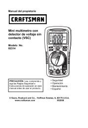
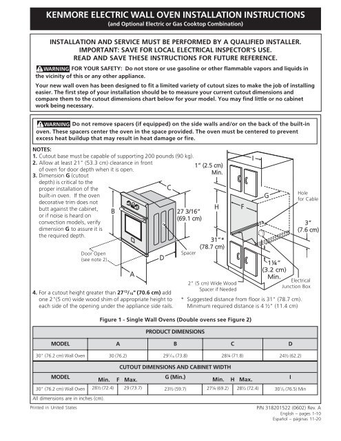
Your new <strong>wall</strong> <strong>oven</strong> has been designed to fit a limited variety of cutout sizes to make the job of installing<br />
easier. The first step of your <strong>installation</strong> should be to measure your current cutout dimensions and<br />
compare them to the cutout dimensions chart below for your model. You may find little or no cabinet<br />
work being necessary.<br />
Do not remove spacers (if equipped) on the side <strong>wall</strong>s and/or on the back of the built-in<br />
<strong>oven</strong>. These spacers center the <strong>oven</strong> in the space provided. The <strong>oven</strong> must be centered to prevent<br />
excess heat buildup that may result in heat damage or fire.<br />
NOTES:<br />
1. Cutout base must be capable of supporting 200 pounds (90 kg).<br />
2. Allow at least 21" (53.3 cm) clearance in front<br />
of <strong>oven</strong> for door depth when it is open.<br />
3. Dimension G (cutout<br />
1” (2.5 cm)<br />
Min.<br />
depth) is critical to the<br />
proper <strong>installation</strong> of the<br />
built-in <strong>oven</strong>. If the <strong>oven</strong><br />
C<br />
decorative trim does not<br />
butt against the cabinet,<br />
or if noise is heard on<br />
convection models, verify<br />
dimension G to assure it is<br />
B<br />
27 3/16”<br />
(69.1 cm)<br />
H F<br />
the required depth.<br />
31”*<br />
(78.7 cm)<br />
Door Open<br />
(see note 2)<br />
D<br />
Spacer<br />
4. For a cutout height greater than 27 13 /16" (70.6 cm) add<br />
one 2"(5 cm) wide wood shim of appropriate height to<br />
each side of the opening under the appliance side rails.<br />
MODEL<br />
30" (76.2 cm) Wall Oven<br />
MODEL<br />
30" (76.2 cm) Wall Oven<br />
All dimensions are in inches (cm).<br />
Printed in United States<br />
A<br />
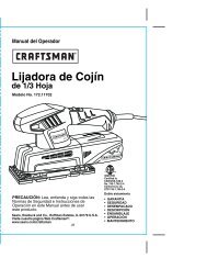
Figure 1 - Single Wall Ovens (Double <strong>oven</strong>s see Figure 2)<br />
A<br />
30 (76.2)<br />
PRODUCT DIMENSIONS<br />
B<br />
29 1 /16 (73.8)<br />
1<br />
2" (5 cm) Wide Wood<br />
Spacer if Needed<br />
CUTOUT DIMENSIONS AND CABINET WIDTH<br />
Min. F Max.<br />
G (Min.)<br />
Min. H Max.<br />
28½ (72.4) 29 (73.7) 23½ (59.7) 27¼ (69.2) 28½ (72.4)<br />
C<br />
28¼ (71.8)<br />
I<br />
G<br />
Hole<br />
for Cable<br />
3”<br />
(7.6 cm)<br />
1¼”<br />
(3.2 cm)<br />
Min.<br />
Electrical<br />
Junction Box<br />
* Suggested distance from floor is 31" (78.7 cm).<br />
Minimum required distance is 4 ½" (11.4 cm)<br />
D<br />
24½ (62.2)<br />
P/N 318201522 (0602) Rev. A<br />
English – pages 1-10<br />
Español – páginas 11-20<br />
I<br />
30 1 /8 (76.5) Min
KENMORE ELECTRIC WALL OVEN INSTALLATION INSTRUCTIONS<br />
(and Optional Electric or Gas Cooktop Combination)<br />
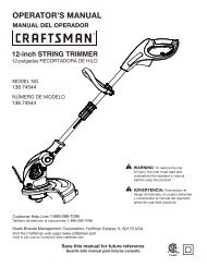
Do not remove spacers (if equipped) on the side <strong>wall</strong>s and/or on the back of the built-in<br />
<strong>oven</strong>. These spacers center the <strong>oven</strong> in the space provided. The <strong>oven</strong> must be centered to prevent<br />
excess heat buildup that may result in heat damage or fire.<br />
Door Open<br />
(see note 2)<br />
B<br />
A<br />
D<br />
C<br />
48 5/8”<br />
(123.5 cm)<br />
NOTES:<br />
1. Cutout base must be capable of supporting 300<br />
pounds (136 kg).<br />
2. Allow at least 21" (53.3 cm) clearance in front of<br />
<strong>oven</strong> for door depth when it is open.<br />
3. Dimension G (cutout depth) is critical to the proper<br />
<strong>installation</strong> of the built-in <strong>oven</strong>. If the <strong>oven</strong><br />
decorative trim does not butt against the cabinet, or<br />
if noise is heard on convection models, verify<br />
dimension G to assure it is according to the required<br />
dimension.<br />
MODEL<br />
30" (76.2 cm) Wall Oven<br />
MODEL<br />
30" (76.2 cm) Wall Oven<br />
All dimensions are in inches (cm).<br />
1” (2.5 cm)<br />
Min.<br />
2<br />
H<br />
11½”<br />
(29.2 cm)<br />
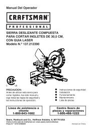
Figure 2- DOUBLE OVENS (Single Ovens see Figure 1)<br />
A<br />
30 (76.2)<br />
Spacer<br />
F<br />
2" (5 cm) Wide Wood<br />
Spacer if Needed<br />
PRODUCT DIMENSIONS<br />
B<br />
50½ (128.3)<br />
CUTOUT DIMENSIONS AND CABINET WIDTH<br />
I<br />
G<br />
Hole for<br />
Cable<br />
1¼”<br />
(3.2 cm)<br />
Min.<br />
3” (7.6 cm)<br />
Max.<br />
Electrical<br />
Junction Box<br />
4. For a cutout height greater than 49¼" (125.1 cm)<br />
add a 2" (5 cm) wide wood shim of appropriate<br />
height to each side of the opening under the<br />
appliance side rails.<br />
Min. F Max. G (Min.) Min. H Max.<br />
28½ (72.4) 29 (73.7) 23½ (59.7) 487 /8 (124.1) 497 /8 (126.7)<br />
C<br />
28¼ (71.8)<br />
D<br />
24½ (62.2)<br />
I<br />
30 1 /8 (76.5) Min
KENMORE ELECTRIC WALL OVEN INSTALLATION INSTRUCTIONS<br />
(and Optional Electric or Gas Cooktop Combination)<br />
Important Notes to the Installer<br />
1. Read all <strong>instructions</strong> contained in these <strong>installation</strong><br />
<strong>instructions</strong> before installing the <strong>wall</strong> <strong>oven</strong>.<br />
2. Remove all packing material from the <strong>oven</strong><br />
compartments before connecting the <strong>electric</strong>al supply<br />
to the <strong>wall</strong> <strong>oven</strong>.<br />
3. Observe all governing codes and ordinances.<br />
4. Be sure to leave these <strong>instructions</strong> with the consumer.<br />
5. Oven door may be removed to facilitate <strong>installation</strong>.<br />
6. THESE OVENS ARE NOT APPROVED FOR<br />
STACKABLE OR SIDE-BY-SIDE INSTALLATION.<br />
Important Note to the Consumer<br />
Keep these <strong>instructions</strong> with your Owner's Guide for future<br />
reference.<br />
IMPORTANT SAFETY<br />
INSTRUCTIONS<br />
Be sure your <strong>wall</strong> <strong>oven</strong> is installed and grounded<br />
properly by a qualified installer or service<br />
technician.<br />
This <strong>wall</strong> <strong>oven</strong> must be <strong>electric</strong>ally grounded in<br />
accordance with local codes or, in their absence,<br />
with the National Electrical Code ANSI/NFPA<br />
No.70- latest edition in United Sates, or with CSA<br />
Standard C22.1, Canadian Electrical Code, Part 1, in<br />
Canada.<br />
Stepping, leaning or sitting on the<br />
door of this <strong>wall</strong> <strong>oven</strong> can result in serious injuries<br />
and can also cause damage to the <strong>wall</strong> <strong>oven</strong>.<br />
Never use your <strong>wall</strong> <strong>oven</strong> for warming or heating<br />
the room. Prolonged use of the <strong>wall</strong> <strong>oven</strong> without<br />
adequate ventilation can be dangerous.<br />
The <strong>electric</strong>al power to the <strong>oven</strong> must<br />
be shut off while line connections are being made.<br />
Failure to do so could result in serious injury or<br />
death.<br />
1. Carpentry<br />
Refer to figure 1 or 2 for the dimensions applicable to<br />
your appliance, and the space necessary to receive the<br />
<strong>oven</strong>. The <strong>oven</strong> support surface (cutout base) may be<br />
solid plywood or similar material, however the surface<br />
must be level from side to side and from front to rear.<br />
3<br />
2. Electrical Requirements<br />
This appliance must be supplied with the proper voltage<br />
and frequency, and connected to an individual, properly<br />
grounded branch circuit, protected by a circuit breaker or<br />
fuse. To know the circuit breaker or fuse required by<br />
your model, see the serial plate to find the wattage<br />
consumption and refer to table A to get the circuit<br />
breaker or fuse amperage.<br />
Appliance Protection Appliance Protection<br />
Rating Watts Circuit Rating Watts Circuit<br />
240V recommended 208V recommended<br />
less than 4800W 20A Less than 4100W 20A<br />
4800W - 7200W 30A 4100W - 6200W 30A<br />
7200W - 9600W 40A 6200W - 8300W 40A<br />
9600W and + 50A 8300W and + 50A<br />
Table A<br />
Observe all governing codes and local ordinances<br />
1.A 3-wire or 4-wire single phase 120/240 or 120/208<br />
Volt, 60 Hz AC only <strong>electric</strong>al supply is required on a<br />
separate circuit fused on both sides of the line (red and<br />
black wires). A time-delay fuse or circuit breaker is<br />
recommended. DO NOT fuse neutral (white wire). Only<br />
certain cooktop models may be installed over certain<br />
built-in <strong>electric</strong> <strong>oven</strong> models. Approved cooktops and<br />
built-in <strong>oven</strong>s are listed by the MFG ID number (see<br />
the insert sheet included in the literature package).<br />
NOTE: Wire sizes and connections must conform with<br />
the fuse size and rating of the appliance in accordance<br />
with the American National Electrical Code ANSI/NFPA<br />
No. 70-latest edition, or with Canadian CSA Standard<br />
C22.1, Canadian Electrical Code, Part 1, and local codes<br />
and ordinances.<br />
An extension cord should not be used<br />
with this appliance. Such use may result in a fire,<br />
<strong>electric</strong>al shock, or other personal injury. If you need<br />
a longer power cord you can purchase a 10' (3 m) power<br />
cord kit #903056-9010 by calling the <strong>Sears</strong> Parts &<br />
Repair Center at 1-800-4-MY-HOME ® .<br />
2. These appliances should be connected to the fused<br />
disconnect (or circuit breaker) box through flexible<br />
armored or nonmetallic sheathed cable. The flexible<br />
armored cable extending from the appliance should<br />
be connected directly to the junction box. The<br />
junction box should be located as shown in Figure 1<br />
or Figure 2 and with as much slack as possible<br />
remaining in the cable between the box and the<br />
appliance, so it can be moved if servicing is ever<br />
necessary.<br />
3. A suitable strain relief must be provided to attach<br />
the flexible armored cable to the junction box.
KENMORE ELECTRIC WALL OVEN INSTALLATION INSTRUCTIONS<br />
(and Optional Electric or Gas Cooktop Combination)<br />
Electrical Shock Hazard<br />
Electrical ground is required on this appliance.<br />
Do not connect to the <strong>electric</strong>al supply until<br />
appliance is permanently grounded.<br />
Disconnect power to the junction box before<br />
making the <strong>electric</strong>al connection.<br />
This appliance must be connected to a<br />
grounded, metallic, permanent wiring system,<br />
or a grounding connector should be connected<br />
to the grounding terminal or wire lead on the<br />
appliance.<br />
Do not use a gas supply line for grounding the<br />
appliance.<br />
Failure to do any of the above could result in a<br />
fire, personal injury or <strong>electric</strong>al shock.<br />
In cold weather shipping and storage<br />
conditions, make sure that <strong>oven</strong> is in final location at<br />
least three (3) hours before switching on power.<br />
Switching on power while <strong>oven</strong> is still cold may damage<br />
the <strong>oven</strong> controls.<br />
3. Adjusting Oven Height<br />
Oven height can be adjusted with 2" (5 cm) wide wood<br />
shims when needed to fit into an existing cabinet cutout<br />
opening, when cutout height exceeds 27 13 /16" (70.6 cm)<br />
for the single <strong>wall</strong> <strong>oven</strong> or 49¼" (125.1 cm) for the<br />
double <strong>wall</strong> <strong>oven</strong> (see Figure 1 or 2). Place shims of<br />
appropriate height beneath the <strong>oven</strong> side rails.<br />
4. Electrical connection<br />
It is the responsibility and obligation of the consumer to<br />
contact a qualified installer to assure that the <strong>electric</strong>al<br />
<strong>installation</strong> is adequate and is in conformance with the<br />
National Electrical Code ANSI/NFPA No. 70-latest<br />
edition, or with CSA Standard C22.1, Canadian<br />
Electrical Code, Part 1, and local codes and ordinances.<br />
Electrical ground is required on this appliance.<br />
These appliances are equipped with a copper conductor<br />
flexible cable. If connection is made to aluminum house<br />
wiring, use only special connectors which are approved<br />
for joining copper and aluminum wires in accordance<br />
with National Electrical Code and local codes and<br />
ordinances.<br />
These appliances are manufactured with a white neutral<br />
power supply wire and a frame connected green or bare<br />
copper grounding wire.<br />
4<br />
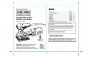
Where local codes permit connecting the appliance<br />
cable ground wire to the power supply cable<br />
neutral (white) wire (see figure 3):<br />
1. Disconnect the power supply.<br />
2. In the circuit breaker, fuse box or junction box:<br />
connect appliance and power supply cable wires as<br />
shown in Figure 3.<br />
White Wire<br />
(Neutral)<br />
Red<br />
Wires<br />
Cable from Power Supply<br />
Black<br />
Wires<br />
Junction<br />
Box<br />
White Wire<br />
(Neutral)<br />
Ground Wire<br />
U.L.-Listed Conduit<br />
(Bare or Green Wire) Connector (or CSA listed)<br />
Cable from appliance<br />
Figure 3 - 3-WIRE GROUNDED JUNCTION BOX<br />
Improper connection of aluminum<br />
house wiring to copper leads can result in a short<br />
circuit or fire. Use only connectors designed for<br />
joining copper to aluminum, and follow the<br />
manufacturer's recommended procedure closely.
KENMORE ELECTRIC WALL OVEN INSTALLATION INSTRUCTIONS<br />
(and Optional Electric or Gas Cooktop Combination)<br />
You may not ground the <strong>oven</strong><br />
through the neutral (white) wire if <strong>oven</strong> is used in<br />
a new branch circuit <strong>installation</strong> (1996 NEC), mobile<br />
home, recreational vehicle, or where local codes do<br />
not permit grounding through the neutral (white)<br />
wire. When grounding through the neutral (white)<br />
wire is prohibited, you must use a 4-wire power<br />
supply cable. See Figure 4. Failure to heed this<br />
warning may result in electrocution or other<br />
serious personal injury.<br />
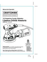
If <strong>oven</strong> is used in a new branch circuit <strong>installation</strong><br />
(1996 NEC), mobile home, recreational vehicle, or<br />
where local codes DO NOT permit connecting the<br />
appliance cable ground wire to the power supply<br />
cable neutral (white) wire, you must use a 4-wire<br />
power supply cable (see figure 4):<br />
1. Disconnect the power supply.<br />
2. In the circuit breaker, fuse box or junction box:<br />
connect appliance and power supply cable wires as<br />
shown in Figure 4.<br />
Ground Wire<br />
Red<br />
Wires<br />
Ground Wire<br />
(Bare or Green<br />
Wire)<br />
Junction Box<br />
Cable from Power Supply<br />
Cable from appliance<br />
White Wire<br />
Black<br />
Wires<br />
White Wire<br />
U.L.-Listed Conduit<br />
Connector (or CSA listed)<br />
Figure 4 - 4-WIRE GROUNDED JUNCTION BOX<br />
DO NOT ground to a gas supply pipe. DO NOT connect<br />
to <strong>electric</strong>al power supply until appliance is permanently<br />
grounded. Connect the ground wire before turning on<br />
the power (Figure 4).<br />
If connecting to a 4-wire <strong>electric</strong>al<br />
system (mobile homes), the appliance frame MUST<br />
NOT be connected to the neutral wire of the 4-wire<br />
<strong>electric</strong>al system.<br />
NOTE TO ELECTRICIAN: The armored cable leads<br />
supplied with the appliance are UL-recognized for<br />
connection to larger gauge household wiring. The<br />
insulation of the leads is rated at temperatures much<br />
higher than temperature rating of household wiring. The<br />
current carrying capacity of the conductor is governed by<br />
the temperature rating of the insulation around the wire,<br />
rather than the wire gauge alone.<br />
5<br />
Heavy Weight Hazard<br />
Use 2 or more people to move and install <strong>wall</strong> <strong>oven</strong>.<br />
Failure to follow this instruction can result in<br />
personal injury or damage to the unit.<br />
5. Cabinet Installation<br />
The <strong>wall</strong> <strong>oven</strong> can tip when the door<br />
is open. The mounting brackets supplied with the<br />
<strong>wall</strong> <strong>oven</strong> must be attached to the cabinet and the<br />
appliance to prevent tipping of the <strong>wall</strong> <strong>oven</strong> and<br />
injury to persons.<br />
Mounting Brackets Installation Instructions<br />
1. Unpack the <strong>wall</strong> <strong>oven</strong>. Remove the lower trim taped<br />
on the <strong>oven</strong> side panel. Find the 2 mounting brackets<br />
and screws included in the literature package.<br />
2. Install the mounting brackets in the <strong>wall</strong> cabinet as<br />
shown on Figure 5. Note: To prevent damage to<br />
cabinet, it is recommended to drill 1/16" (0.16 cm) dia.<br />
pilot holes before installing the mounting brackets.<br />
Mounting Brackets<br />
22 3/16" *<br />
(56.4 cm)<br />
Mounting Brackets<br />
43 5/8" *<br />
(110.8 cm)<br />
F see figure 1<br />
F see figure 2 Double Wall <strong>oven</strong>s<br />
Figure 5<br />
Single Wall <strong>oven</strong>s<br />
H<br />
see figure 1<br />
H<br />
see figure 2<br />
* If wood shims are installed please calculate this<br />
dimension from the top of the shim to the middle of<br />
the mounting bracket.
KENMORE ELECTRIC WALL OVEN INSTALLATION INSTRUCTIONS<br />
(and Optional Electric or Gas Cooktop Combination)<br />
IMPORTANT<br />
Do not lift the <strong>oven</strong> by the door handle.<br />
3.Insert the <strong>oven</strong> into the cabinet opening. Slide <strong>oven</strong><br />
inward leaving 1½" (3.8 cm) clearance between the <strong>oven</strong><br />
and front of cabinet (see Figure 6). Pull the appliance<br />
cable through the hole for it in the cabinet and toward the<br />
junction box while moving the appliance inward.<br />
Figure 6<br />
1½" (3.8 cm)<br />
clearance<br />
between unit<br />
4.Push the <strong>oven</strong> in and against the cabinet; the <strong>oven</strong> side<br />
bracket will clip into the mounting bracket installed into<br />
the side of cabinet.<br />
To pull out the <strong>oven</strong> for servicing you must use the two<br />
tools supplied with the <strong>oven</strong>. Insert one tool into hole in<br />
each side of <strong>oven</strong> frame. Holes are visible when door is<br />
opened. After inserting tools pull the <strong>oven</strong> towards you<br />
(see Figure 7).<br />
5.Lower Trim Installation:<br />
Fix the lower trim in place using the 2 screws supplied in<br />
the mounting holes located on each side trim below the<br />
<strong>oven</strong> frame (see figure 8). Use a long screwdriver shaft<br />
to reach the side trim mounting holes below the door. If<br />
necessary, you can also remove the <strong>oven</strong> door (see the<br />
proper section in your Use & Care Guide) to help you fix<br />
the lower trim in place.<br />
6<br />
Oven<br />
side<br />
trim<br />
Oven<br />
Screws<br />
supplied<br />
Mounting<br />
bracket installed<br />
1 in cabinet 2 3<br />
Cabinet<br />
Right<br />
Side<br />
Tool<br />
Mounting<br />
bracket<br />
released<br />
Figure 7<br />
Figure 8<br />
Hole where to<br />
insert the tool<br />
Lower Trim<br />
Oven removed<br />
from the cabinet
KENMORE ELECTRIC WALL OVEN INSTALLATION INSTRUCTIONS<br />
(and Optional Electric or Gas Cooktop Combination)<br />
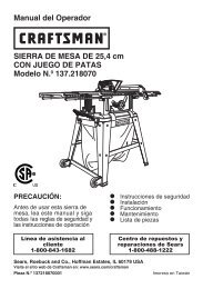
6.For typical under counter <strong>installation</strong> of an <strong>electric</strong> built-in <strong>oven</strong> see Figure below.<br />
Only certain cooktop models may be installed over certain<br />
built-in <strong>electric</strong> <strong>oven</strong> models. Approved cooktops<br />
and built-in <strong>oven</strong>s are listed by the MFG ID number and<br />
product code (see the insert sheet included in the literature<br />
package and cooktop <strong>installation</strong> <strong>instructions</strong> for the<br />
dimensions).<br />
To reduce the risk of<br />
personal injury and<br />
tipping of the <strong>wall</strong><br />
<strong>oven</strong>, the <strong>wall</strong> <strong>oven</strong><br />
must be secured to<br />
the cabinet (s) by<br />
mounting brackets.<br />
208/240 Volt junction box<br />
for built-in <strong>oven</strong>.<br />
Approx. 3”<br />
(7.5 cm)<br />
G<br />
4-1/2” (11.5 cm) Max. distance*<br />
* If no cooktop is installed directly over<br />
the <strong>oven</strong> unit, 5” (12.7 cm) maximum<br />
is allowed above the floor.<br />
30" (76.2 cm)<br />
Wall Oven<br />
7<br />
F<br />
Cabinet side filler panels are<br />
necessary to isolate the unit<br />
from adjoining cabinets. Cabinet<br />
side filler height should allow for<br />
<strong>installation</strong> of approved cooktop<br />
models<br />
H<br />
36” Min.<br />
(91.4 cm) Min.<br />
Use 3/4” (1.9 cm) plywood, installed<br />
on two runners, flush with toe plate.<br />
Base must be capable of supporting<br />
200 pounds (90 kg).<br />
Cut an opening in wood base minimum 9” x 9”<br />
(23 X 23 cm), 2” (5 cm) from left side filler<br />
panel, to route armoured cable to junction box.<br />
CUTOUT DIMENSIONS<br />
F.WIDTH G.DEPTH H.HEIGHT<br />
28½" (72.4 cm) Min.<br />
29" (73.7 cm) Max.<br />
23½" (59.7 cm) Min.<br />
Figure 9 - TYPICAL UNDER COUNTER INSTALLATION OF A SINGLE ELECTRIC BUILT-IN OVEN<br />
WITH AN ELECTRIC COOKTOP MOUNTED ABOVE<br />
27¼" (69.2 cm) Min.<br />
28½" (72.4 cm) Max.
KENMORE ELECTRIC WALL OVEN INSTALLATION INSTRUCTIONS<br />
(and Optional Electric or Gas Cooktop Combination)<br />
Wall Oven Cabinet<br />
Flexible Appliance Conduit<br />
Wall Oven Cabinet<br />
side or filler panel<br />
5” Max.<br />
(12.7 cm)<br />
Flare<br />
Union<br />
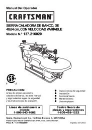
Figure 10 - TYPICAL UNDER COUNTER INSTALLATION OF A SINGLE ELECTRIC BUILT-IN OVEN<br />
WITH A GAS COOKTOP ABOVE<br />
8<br />
18”(45.7 cm) Max.<br />
6 1/2” Min.<br />
(16.5 cm)<br />
Flare<br />
Union<br />
120V/60Hz<br />
Grounded<br />
Outlet<br />
Pressure<br />
Regulator<br />
4”(10 cm)<br />
Manual Shutoff Valve<br />
(To be accessible for shut-off<br />
valve operation)
KENMORE ELECTRIC WALL OVEN INSTALLATION INSTRUCTIONS<br />
(and Optional Electric or Gas Cooktop Combination)<br />
6. Leveling the Wall Oven<br />
1. Install an <strong>oven</strong> rack in the center of the upper <strong>oven</strong><br />
(see Figure 11).<br />
2. Place a level on the rack. Take 2 readings with the<br />
level placed diagonally in one direction and then the<br />
other. Use wood shims under the <strong>wall</strong> <strong>oven</strong> to level<br />
if necessary.<br />
3. Repeat in the lower <strong>oven</strong> if you have a double cavity<br />
<strong>wall</strong> <strong>oven</strong>. If the level indicates that the rack is not<br />
level, use wood shims to reach a compromise for<br />
both <strong>oven</strong>s.<br />
Figure 11<br />
IMPORTANT NOTE<br />
A cooling fan inside the upper rear part<br />
above the <strong>oven</strong> provides cooling of the<br />
<strong>oven</strong> <strong>electric</strong>al and electronic<br />
components. If the <strong>oven</strong> has been<br />
operating at high temperatures, the fan<br />
will continue to run after the <strong>oven</strong> is<br />
turned off.<br />
On the double <strong>wall</strong> <strong>oven</strong>, both cooling<br />
fans can be ON when one of the <strong>oven</strong>s<br />
is used in cleaning mode. This is<br />
normal. This is to provide cool<br />
temperature to the components inside<br />
your appliance.<br />
9<br />
7. Checking Operation<br />
Your model is equipped with an Electronic Oven<br />
Control. Each of the functions has been factory checked<br />
before shipping. However, it is suggested that you verify<br />
the operation of the electronic <strong>oven</strong> controls once more.<br />
Refer to the Use and Care Guide for operation.<br />
1. Remove all items from the inside of the <strong>oven</strong>.<br />
2. Turn on the power to the <strong>oven</strong> (Refer to your Use &<br />
Care Guide.)<br />
3. Verify the operation of the electronic <strong>oven</strong> controls:<br />
Bake - Verify that this function makes the <strong>oven</strong> hot.<br />
20 seconds after turning <strong>oven</strong> on, open the door and<br />
you should feel heat coming from the <strong>oven</strong>.<br />
Broil - When the <strong>oven</strong> is set to BROIL, the upper<br />
element in the <strong>oven</strong> should become red.<br />
Convection–When the <strong>oven</strong> is set for convection<br />
baking or roasting the convection fan will run. The<br />
convection fan will stop running when the <strong>oven</strong> door is<br />
opened.<br />
Model and Serial Number Location<br />
The serial plate is located along the interior side trim of<br />
the <strong>oven</strong> and visible when the door is opened.<br />
When ordering parts for or making inquires about your<br />
<strong>oven</strong>, always be sure to include the model and serial<br />
numbers and a lot number or letter from the serial plate<br />
on your <strong>oven</strong>.<br />
Before You Call for Service<br />
Read the Before You Call for Service Checklist and<br />
operating <strong>instructions</strong> in your Use and Care Guide. It<br />
may save you time and expense. The list includes<br />
common occurrences that are not the result of defective<br />
workmanship or materials in this appliance.<br />
Refer to your Use and Care Guide for <strong>Sears</strong> service<br />
phone numbers, or call 1-800-4-MY-HOME ® .
Notes<br />
KENMORE ELECTRIC WALL OVEN INSTALLATION INSTRUCTIONS<br />
(and Optional Electric or Gas Cooktop Combination)<br />
10
INSTRUCCIONES DE INSTALACIÓN PARA EL HORNO ELECTRICO DE PARED KENMORE<br />
(Combinado con una cocina <strong>electric</strong>a o de gas facultativa)<br />
LA INSTALACION Y EL SERVICIO DEBEN SER EFECTUADOS POR UN INSTALADOR CALIFICADO.<br />
IMPORTANTE: GUARDE ESTAS INSTRUCCIONES PARA USO DEL INSPECTOR LOCAL DE<br />
ELECTRICIDAD. LEA Y GUARDE ESTAS INSTRUCCIONES PARA REFERENCIA FUTURA.<br />
PARA SU SEGURIDAD: No almanece ni utilice gasolina u otros vapores y líquidos inflamables<br />
en la proximidad de este o de cualquier otro artefacto.<br />
El primer paso para su instalación debe de ser el de medir las dimensiones de la apertura y compararlas con las<br />
que se indican en el cuadro de dimensiones del hueco de la figura 1. Posiblemente encontrará que algún<br />
trabajo de carpintería será necesario.<br />
No quite los separadores de los muros laterales o/y de la parte posterior del horno<br />
empotrado. Estos espaciadores centran el horno en el espacio provisto. El horno debe estar centrado para<br />
prevenir una concentración excesiva de calor que podría resultar en daños por el calor o un incendio.<br />
NOTAS:<br />
1. La base debe poder sostener 200 libras (90 kg).<br />
2. Deje por lo menos 21" (53.3 cm) de espacio libre<br />
para la profundidad de la puerta cuando esta abierta.<br />
3. La dimensión G<br />
(profundidad del corte)<br />
C<br />
está primordial para<br />
instalar correc-tamente el<br />
horno de pared. Si el<br />
adorno del armazón del B<br />
horno no topa contra el<br />
armario, o si escuche un<br />
ruido, verifique si la<br />
dimensión G está<br />
en conformidad<br />
con la dimensión<br />
requerida.<br />
Puerta Abierta<br />
(vea la nota 2)<br />
4. Para un corte de una altura mayor que 27 13 /16" (70,6 cm)<br />
agregar una cuña de madera de 2" (5 cm) de ancho para<br />
lograr la altura apropiada a cada lado del orificio ubicado<br />
debajo de los rieles laterales del accesorio.<br />
MODELO<br />
Horno de pared 30 (76.2)<br />
MODELO<br />
Horno de pared 30 (76.2)<br />
A<br />
D<br />
27 3/16”<br />
(69.1 cm)<br />
11<br />
1” (2.5 cm)<br />
Min.<br />
31”*<br />
(78.7 cm)<br />
Espaciador<br />
H F<br />
Espaciador de Madera de 2"<br />
(5 cm) de ancho, si es necesario<br />
Figura 1 - Hornos simples de Pared (Para hornos dobles, ver la Figura 2)<br />
Todas las dimensiones se dan en pulgadas (cm).<br />
Imprimido en los Estados Unidos<br />
A<br />
30 (76.2)<br />
DIMENSIONES DEL APARATO<br />
B<br />
29 1 /16 (73.8)<br />
DIMENSIONES DEL HUECO Y ANCHURA DEL ARMARIO<br />
Min. F Max. G (Min.) Min. H Max.<br />
28½ (72.4) 29 (73.7) 23½ (59.7) 27¼ (69.2) 28½ (72.4)<br />
C<br />
28¼ (71.8)<br />
I<br />
G<br />
1¼”<br />
(3.2 cm)<br />
Min.<br />
Orificio<br />
para el<br />
Cable<br />
3”<br />
(7.6 cm)<br />
Caja elétrica<br />
de empalme<br />
* Distancia sugerida desde el suelo es 31" (78.7 cm).<br />
La distancia miníma requerida es 4½" (11.4 cm).<br />
D<br />
24½ (62.2)<br />
I<br />
30 1 /8 (76.5) Min<br />
P/N 318201522 (0603) Rev. A<br />
English – pages 1-10<br />
Español – páginas 11-20
INSTRUCCIONES DE INSTALACIÓN PARA EL HORNO ELECTRICO DE PARED KENMORE<br />
(Combinado con una cocina <strong>electric</strong>a o de gas facultativa)<br />
No quite los separadores de los muros laterales o/y de la parte posterior del horno<br />
empotrado. Estos espaciadores centran el horno en el espacio provisto. El horno debe estar centrado para<br />
prevenir una concentración excesiva de calor que podría resultar en daños por el calor o un incendio.<br />
Puerta Abierta<br />
(vea la nota 2)<br />
NOTES:<br />
1. La base debe poder sostener 300 libras (136 kg).<br />
2. Deje por lo menos 21" (53.3 cm) de espacio libre<br />
para la profundidad de la puerta cuando esta abierta.<br />
3. La dimensión G (profundidad del corte) está<br />
primordial para instalar correctamente el horno de<br />
pared. Si el adorno del armazón del horno no topa<br />
contra el armario, o si escuche un ruido, verifique si<br />
la dimensión G está en conformidad con la dimensión<br />
requerida.<br />
MODELO<br />
Horno de pared 30 (76.2)<br />
MODELO<br />
B<br />
Horno de pared 30 (76.2)<br />
Figura 2 - HORNOS DOBLES (Para hornos simples, ver la Figura 1)<br />
Todas las dimensiones se dan en pulgadas (cm).<br />
A<br />
A<br />
D<br />
30 (76.2)<br />
C<br />
48 5/8”<br />
(123.5 cm)<br />
1” (2.5 cm)<br />
Min.<br />
DIMENSIONES DEL APARATO<br />
B<br />
50½ (128.3)<br />
12<br />
4. Para un corte de una altura mayor que 49¼" (125.1<br />
cm) agregar una cuña de madera de 2" (5 cm) de<br />
ancho para lograr la altura apropiada a cada lado del<br />
orificio ubicado debajo de los rieles laterales del<br />
accesorio.<br />
DIMENSIONES DEL HUECO Y ANCHURA DEL ARMARIO<br />
Min. F Max. G (Min.) Min. H Max.<br />
28½ (72.4) 29 (73.7) 23½ (59.7) 487 /8 (124.1) 497 /8 (126.7)*<br />
H<br />
11½”<br />
(29.2 cm)<br />
F<br />
I<br />
C<br />
G<br />
28¼ (71.8)<br />
Orificio<br />
para el<br />
Cable<br />
1¼”<br />
(3.2 cm)<br />
Min.<br />
3” (7.6 cm)<br />
Max.<br />
Espaciador Caja elétrica de<br />
empalme<br />
Espaciador de Madera de 2" (5 cm)<br />
de ancho, si es necesario<br />
D<br />
24½ (62.2)<br />
I<br />
30 1 /8 (76.5) Min
INSTRUCCIONES DE INSTALACIÓN PARA EL HORNO ELECTRICO DE PARED KENMORE<br />
(Combinado con una cocina <strong>electric</strong>a o de gas facultativa)<br />
Notas importantes para el instalador<br />
1. Lea todas las instrucciones contenidas en este manual<br />
antes de instalar el horno.<br />
2. Saque todo el material usado en el embalaje del<br />
compartimiento del horno antes de conectar el<br />
suministro eléctrico o de gas a la estufa.<br />
3. Observe todos los códigos y reglamentos pertinentes.<br />
4. Deje estas instrucciones con el consumidor.<br />
5. La puerta del horno se puede retirar para facilitar la<br />
instalación.<br />
6. ESTE HORNO NO ESTÁ APROBADO PARA LA<br />
INSTALACIÓN APILABLE O DE LADO A LADO.<br />
Nota importante al consumidor<br />
Conserve estas instrucciones y el manual del usuario para<br />
referencia futura.<br />
INSTRUCCIONES<br />
IMPORTANTES DE SEGURIDAD<br />
Asegúrese de que su horno de pared sea instalado<br />
y puesto a tierra de forma apropiada por un<br />
instalador calificado o por un técnico de servicio.<br />
Este horno de pared debe ser eléctricamente<br />
puesto a tierra de acuerdo con los códigos locales<br />
o, en su ausencia, con el Código Eléctrico Nacional<br />
ANSI/NFPA No. 70–última edición en los Estados<br />
Unidos, o el Código Eléctrico Canadiense CSA<br />
Standard C22.1, Part 1, en Canadá.<br />
Pisar, apoyarse, o sentarse sobre la<br />
puerta de este horno de pared puede causar serias<br />
lesiones y daños al horno de pared.<br />
Nunca use su horno de pared para calentar una<br />
habitación. El uso prolongado de la estufa sin la<br />
ventilación adecuada puede ser peligroso.<br />
La corriente eléctrica al horno debe<br />
estar apagada mientras se hacen las conexiones de<br />
líneas. Si no se apaga, daños serios o la muerte<br />
podrían resultar.<br />
1. Carpintería<br />
Consulte la Figura 1 o la figura 2 para conocer las dimensiones<br />
pertinentes al modelo de su horno y al espacio<br />
necesario en el que poner el horno. La superficie donde se<br />
va a apoyar el horno debe de ser de madera<br />
contrachapada sólida u otro material similar y, sobre todo,<br />
la superficie tiene que estar a nivel, de lado a lado, y de<br />
atrás hacia adelante.<br />
13<br />
2. Requerimientos Eléctricos<br />
Se debe proveer el voltaje y la frecuencia apropiados a este<br />
electrodoméstico, y conectarse a un circuito individual<br />
correctamente puesto a tierra, protegido por un interruptor o<br />
un fusible. Para conocer el interruptor o fusible que requirie<br />
su modelo, vea la placa serial para encontrar la consomación<br />
del vatiaje y refierase al cuadro A para encontrar el amperaje<br />
del interruptor o fusible.<br />
Grados de Vatios<br />
del<br />
electrodoméstico<br />
240V<br />
Menos de 4800W<br />
4800W - 7200W<br />
7200W - 9600W<br />
9600W y +<br />
Se recomienda<br />
una protección<br />
al circuito<br />
20A<br />
30A<br />
40A<br />
50A<br />
Grados de Vatios<br />
del<br />
electrodoméstico<br />
208V<br />
Menos de 4100W<br />
4100W - 6200W<br />
6200W - 8300W<br />
8300W y +<br />
Se recomienda<br />
una protección<br />
al circuito<br />
20A<br />
30A<br />
40A<br />
50A<br />
Table A<br />
Observe todos los códigos que gobiernan y ordenanzas<br />
locales<br />
1. Un cable de 3 o 4 alambres monofásico 120/240 o 120/<br />
208 voltios, 60 hertzios es la unica fuente eléctrica que<br />
requiere en un circuito separado en ambos lados de la<br />
línea (alambre negro y alambre rojo) (se recomienda un<br />
fusible o un interruptor de retraso de tiempo). No funda a<br />
cable neutro (alambre blanco). Se debe de tener precaucion<br />
al combinar un horno de pared y una cubierta, refierase a<br />
la placa de seria de cada uno de los aparatos.<br />
NOTA: Los tamaños y las conexiones del alambre deben<br />
conformarse con el tamaño del fusible y el grado de la<br />
aplicación de acuerdo con el código Eléctrico Nacional<br />
Americano ANSI/NFPA No. 70- ultima edición, o con el<br />
estándar CSA canadiense C22.1 , código eléctrico<br />
canadiense, parte 1, y códigos y ordenanzas locales.<br />
No se debera usar extensiones para<br />
enchufar este electrodoméstico. Esto podría causar<br />
un incendio, choque eléctrico u otro tipo de daño<br />
personal. Si usted necesita un cable mas largo, puede<br />
ordernar un cable de 10" kit 903056-9010 llamando al<br />
centro de Partes y Servicion <strong>Sears</strong> al 1-888-SU-HOGARSM .<br />
2. Este electrodoméstico debe conectarse a la caja de<br />
fusibles (o de cortacircuito), por medio de un cable<br />
blindado flexible o un cable con forro no metálico. El<br />
cable blindado flexible que va desde el electrodoméstico<br />
debe de estar conectado directamente a la caja de<br />
empalme. La caja de empalme debe de estar localizada<br />
en el lugar que se indica en la Figura 1 o 2, dejando<br />
tanto exceso de cable como sea posible entre la caja y<br />
el electrodoméstico, de forma que así el electrodoméstico<br />
se pueda mover fácilmente, si fuera necesario para<br />
hacer una reparación.<br />
3. Se debe de usar un conector que reduzca la tirantez de<br />
una forma adecuada para unir el cable blindado flexible<br />
a la caja de empalme.
INSTRUCCIONES DE INSTALACIÓN PARA EL HORNO ELECTRICO DE PARED KENMORE<br />
(Combinado con una cocina <strong>electric</strong>a o de gas facultativa)<br />
Riesgo de choque eléctrico<br />
Una puesta a tierra se require en este aparato.<br />
No lo conecte a la corriente eléctrica hasta que<br />
el aparato haya sido puesto a tierra.<br />
Desconecte la corriente eléctrica a la caja de<br />
empalmes antes de hacer la conexión eléctrica.<br />
Este aparato debe estar conectado con un<br />
sistema de alambres puesto en tierra, metálico<br />
y permanente o un conector de pueta a tierre<br />
debe conectarse al terminal de puesta a tierra<br />
o el alambre conductor en al aparato.<br />
No utilice el suministro de gas para hacer la<br />
puesta a tierra.<br />
La falta de cualquiera de las instrucciones<br />
mencionadas podría resultar en un incendio,<br />
choque eléctrico o lesiones personales.<br />
En cuanto a las condiciones de despacho<br />
y almacenamiento en el invierno, asegúrese de que el<br />
horno llegue a su destino final como mínimo tres (3)<br />
horas antes de encenderlo. Si se enciende el horno<br />
cuando aún está frío, se pueden dañar los controles.<br />
3. Ajuste de la altura del horno<br />
La altura del horno se puede ajustar con cuñas de madera<br />
de 2" (5 cm) de ancho, donde sea necesario, para que<br />
quepa en un gabinete o abertura existente, cuando la<br />
altura del corte es superior a 2713/16" (70,6 cm) en el<br />
caso del horno único de pared o 49¼” (125.1 cm) en el<br />
caso del horno doble de pared (ver la Figura 1 ó 2). Colocar<br />
las cuñas de altura apropiada debajo de los rieles laterales<br />
del horno.<br />
4. Conexión eléctrica<br />
El usuario tiene la responsabilidad personal y obligación<br />
de utilizar un instalador calificado, para asegurar que la<br />
instalación eléctrica está hacha de forma adecuada y<br />
está conforme con el Código Eléctrico Nacional ANSI/<br />
NFPA No. 70-última edición en los Estados Unidos, o el<br />
Código Eléctrico Canadiense CSA Standard C22.1, Part<br />
1, en Canadá.<br />
En este electrodomestico se necesita un cable de<br />
toma a tierra.<br />
Este electrodoméstico viene equipado con un cable de<br />
conexión de cobre. Si esto tuviera que conectarse a los<br />
cables de aluminio de una casa, use solamente los<br />
conectores especiales aprobados para empalmes de<br />
cobre y aluminio, de acuerdo con el Código Eléctrico<br />
Nacional y los reglamentos y códigos locales.<br />
Este electrodoméstico se ha fabricado con un cable para<br />
el suministro de energía que tiene un alambre neutro de<br />
color blanco y un alambre pelado de toma a tierra<br />
conectado al armazón.<br />
14<br />
Donde los códigos locales permitan conectar el<br />
conductor de puesta a tierra del eléctrodoméstico al<br />
neutral (blanco) (vea figura 3):<br />
(Un cordón flexible o cable de 3 conductores debe de ser<br />
reemplazado con un cordón flexible o cable de 4 conductores<br />
donde la conexión del conductor a tierra al neutro esta<br />
prohibida en las nuevas instalaciones (1996 NEC), las casas<br />
sobre ruedas, los vehículos de recreación o otras áreas<br />
donde los códigos locales no permiten la conexión a tierra<br />
al neutro.)<br />
1. Desconecte el suministro eléctrico.<br />
2. En el interruptor automático, caja de fusibles o caja de<br />
juntas: conectar el aparato y los cables residenciales<br />
como se muestra en la figura 3.<br />
Cable desde el suministro de energía<br />
Alambre<br />
desnudo<br />
Alambre<br />
rojos<br />
Alambre verde<br />
o desnudo<br />
Cable de la estufa<br />
Figura 3 - CAJA DE EMPALMES<br />
DE 3 ALAMBRES PUESTA A TIERRA<br />
Caja de<br />
empalmes<br />
Alambre<br />
desnudo<br />
Conductor de<br />
unión listado-UL<br />
(o CSA)<br />
Alambre<br />
negros<br />
Una conexión incorrecta del<br />
alambrado de aluminio con los conductores de cobre<br />
puede resultar en un cortacircuito o incendio. Use<br />
solamente los conectores diseñados para juntar el<br />
cobre con el aluminio y siga exactamente el<br />
procedimiento recomendado por el fabricante.<br />
No se puede conectar a tierra el<br />
horno a través del cable neutral (blanco) si el horno<br />
es usado en una instalación de circuito de ramal<br />
nuevo (1996 NEC), en una casa rodante, en un<br />
vehículo para recreación o si los códigos locales no<br />
permiten la conexión a tierra a través del cable<br />
neutral (blanco). Si está prohibida la conexión a<br />
tierra a través del cable neutral (blanco), se debe<br />
usar un cable de alimentación de 4 hilos. Ver la<br />
Figura 4. Si no se observa esta advertencia, esto<br />
puede resultar en electrocución o en otra lesión<br />
personal grave.
INSTRUCCIONES DE INSTALACIÓN PARA EL HORNO ELECTRICO DE PARED KENMORE<br />
(Combinado con una cocina <strong>electric</strong>a o de gas facultativa)<br />
Si el horno se usa en una instalación de circuito de<br />
ramal nuevo (1996 NEC), en una casa rodante, en un<br />
vehículo para recreación o si los códigos locales NO<br />
permiten la conexión a tierra a través del cable<br />
neutral (blanco) (ver figura 4):<br />
1. Desconecte el suministro eléctrico.<br />
2. En el interruptor automático, caja de fusibles o caja de<br />
juntas: conectar el aparato y los cables residenciales<br />
como se muestra en la figura 4.<br />
Cable desde el suministro de energía<br />
Alambre<br />
desnudo<br />
Alambre blanco<br />
Alambre<br />
rojos<br />
Alambre<br />
verde o<br />
desnudo<br />
Alambre<br />
negros<br />
Alambre blanco<br />
Caja de<br />
Conductor de unión<br />
empalmes<br />
listado-UL (o CSA)<br />
Cable de la estufa<br />
Figura 4- CAJA DE EMPALMES<br />
DE 4 ALAMBRES PUESTA A TIERRA<br />
NO conecte el alambre puesto a tierra a una tubería de<br />
suministro de gas. NO conecte el suministro de energía<br />
eléctrica hasta que el electrodomestico haya sido<br />
permanentemente puesto a tierra. Conecte el alambre de<br />
puesto a tierra antes de enchufar por primera vez el<br />
electrodomestico.<br />
Si está conectado a un sistema<br />
eléctrico de 4 alambres, el armazón del<br />
electrodoméstico NO TIENE QUE estar conectado al<br />
alambre neutro del sistema eléctrico de 4 alambres.<br />
NOTA AL ELECTRICISTA: Los conductores de cable<br />
blindados provistos con este artefacto son aprobados por<br />
UL para la conexión al alambrado de casa de un calibre<br />
mayor. El aislamiento de los conductores está calificado<br />
para temperaturas más altas que las del alambrado de<br />
la casa. La capacidad de corriente del conductor está<br />
gobernada por la calificación de la temperatura del<br />
aislamiento alrededor del alambre en vez de solamente<br />
el calibre del alambre.<br />
Peligro de Peso Pesado<br />
Use 2 personas o más para mover e instalar el horno<br />
de pared.<br />
Si no cumple con esta instrucción, puede resultar<br />
en lesiones pesonales o daños al horno de pared<br />
15<br />
5. Instalación del Gabinete<br />
El horno de pared puede inclinarse<br />
cuando la puerta esta abierta. Los soportes de<br />
montaje que vienen con el horno de pared deben<br />
de estar ajustadas al armario y al aparato para<br />
evitar que el horno de pared se incline y ocasione<br />
quemaduras graves.<br />
Instrucciones de instalación de los soportes de<br />
montaje<br />
1. Desembalar el horno de pared. Extraer la guarnición<br />
inferior con cinta al panel lateral del horno. Buscar las<br />
dos ménsulas antideslizables y los tornillos que se<br />
incluyen en el paquete de literatura.<br />
2. Instale los soportes de montaje como en la figura 5. Nota:<br />
Para prevenir cualquier tipo de daño al cabinete es<br />
recomendable perforar agujeros conn un diametro de<br />
1/16" (0,16cm) antes de instalar los soportes de<br />
montaje.<br />
22 3/16" *<br />
(56.4 cm)<br />
43 5/8" *<br />
(110.8 cm)<br />
F vea figura 1<br />
Soportes de<br />
montaje<br />
Horno de pared simple<br />
F vea figura 2<br />
Soportes de<br />
montaje<br />
Figura 5<br />
H<br />
vea figura 1<br />
H<br />
vea figure 2<br />
Horno de pared doble<br />
* Si hay instaladas cuñas de madera, calcular esta<br />
dimensión desde la parte superior de la cuña hasta el<br />
medio del soporte de montaje.
INSTRUCCIONES DE INSTALACIÓN PARA EL HORNO ELECTRICO DE PARED KENMORE<br />
(Combinado con una cocina <strong>electric</strong>a o de gas facultativa)<br />
IMPORTANTE<br />
No levante el horno por la manija de la puerta.<br />
3.Insertar el horno en la abertura del gabinete. Deslizar el<br />
horno hacia dentro dejando 1½” (3,8 cm) de espacio<br />
libre entre el horno y la parte delantera del gabinete (ver<br />
la Figura 6). Empujar el cable blindado a través del<br />
orificio del gabinete y hacia la caja de paso mientras se<br />
desliza el accesorio hacia adentro.<br />
Figura 6<br />
1 1/2" (3.8 cm)<br />
distancía entre la<br />
unidad y el gabinete<br />
4.Empujar el horno hacia adentro y en contra del gabinete;<br />
la ménsula lateral del horno enganchará en los soportes<br />
de montaje instalados en el lado del gabinete.<br />
Para extraer el horno en caso de reparación, usar las dos<br />
herramientas provistas con el horno. Insertar una<br />
herramienta en el orificio a cada costado del marco del<br />
horno. Los orificios se pueden ver cuando la puerta está<br />
abierta. Después de insertar las herramientas, extraer el<br />
horno hacia fuera (ver la Figura 7).<br />
5. Instalación de la moldutra inferior:<br />
Fije la moldura inferior usando los 2 tornillos provistos en<br />
los agujeros de montaje localizados en cada moldura lateral<br />
debajo del marco del horno (véase el cuadro 8). Es preferible<br />
usar un destornillador largo para alcanzar los agujeros de<br />
la moldura lateral debajo de la puerta. Si es necesario,<br />
usted puede también quitar la puerta del horno (véase la<br />
sección apropiada en su guía de cuidado) para ayudarle a<br />
fijar la moldura inferior.<br />
16<br />
Bracket<br />
del<br />
horno<br />
Horno<br />
Tornillos<br />
provistos<br />
Soporte de<br />
montaje<br />
1 instalado en el 2 3<br />
gabinete<br />
Cabinete<br />
Lateral<br />
derecho<br />
herramienta<br />
incluida<br />
soporte de<br />
montaje<br />
liberado<br />
Figura 7<br />
Figura 8<br />
Guarnición<br />
Inferior<br />
Horno retirado<br />
del gabinete<br />
Introduzca la<br />
herramienta que trae<br />
el electrodoméstico en<br />
el hoyo.
INSTRUCCIONES DE INSTALACIÓN PARA EL HORNO ELECTRICO DE PARED KENMORE<br />
(Combinado con una cocina <strong>electric</strong>a o de gas facultativa)<br />
6.Para una instalación típica de un horno eléctrico incorporado debajo del mostrador, veáse la figura 8.<br />
Sólo ciertos modelos de tapas de cocina se pueden instalar sobre<br />
ciertos modelos de hornos eléctricos empotrados. Las tapas de cocina<br />
y los hornos empotrados se mencionan por su número de<br />
identificación MFG ID y código de producto (ver la planilla que se<br />
incluye en el paquete de literatura y las instrucciones de instalación<br />
de la cocina donde están detalladas las dimensiones).<br />
Para reducir el riesgo de<br />
lesiones personales y<br />
inclinación del horno de<br />
pared, éste debe<br />
asegurarse a los<br />
gabinetes mediante<br />
soportes de montaje.<br />
208/240 caja de empalme<br />
para hornos de pared<br />
Approx. 3”<br />
(7.5 cm)<br />
G<br />
17<br />
F<br />
H<br />
36” Min.<br />
(91.4 cm) Min.<br />
4 1/2” (11.5 cm) Max.*<br />
* Si no se instala ninguna tapa de cocina directamente<br />
sobre la unidad del horno, se permite un espacio<br />
máximo de 5" (12,7 cm) sobre el piso.<br />
27" (68.6 cm)<br />
Horno de pared<br />
30" (76.2 cm)<br />
Horno de pared<br />
Los paneles de relleno laterales del<br />
gabinete son necesarios para aislar la<br />
unidad de los gabinetes adyacentes.<br />
La altura del relleno lateral del<br />
gabinete debe permitir la instalación<br />
de modelos de tapas de cocina<br />
aprobados.<br />
Instale contrachapado de 3/4" (1.9 cm)<br />
sobre dos correderas, nivelado con la parrilla<br />
inferior. La base debe poder sostener 150<br />
libras (68 kg) para los modelos 27" y 200<br />
libras (90 kg) para los modelos 30".<br />
Corte una abertura de 9" X 9"(23 cm X 23 cm)<br />
(mínimo) en el fondo del contrachapado, a 2" (5 cm)<br />
del lado izquierdo del panel llenador, para poder<br />
encaminar el cable a la caja de empalme.<br />
DIMENSIONES DE ABERTURA<br />
F. ANCHURA<br />
24 7 /8" (63.2 cm) Min.<br />
25¼" (64.1 cm) Max.<br />
28½" (72.4 cm) Min.<br />
29" (73.7 cm) Max.<br />
G. PROFUNDIDAD<br />
23½" (59.7 cm) Min.<br />
23½" (59.7 cm) Min.<br />
Figura 8 – INSTALACIÓN TÍPICA DEBAJO DE LA MESADA DE HORNO SIMPLE EMPOTRADO<br />
CON TAPA DE COCINA MONTADA<br />
H. ALTURA<br />
27¼" (69.2 cm) Min.<br />
28½" (72.4 cm) Max.<br />
27¼" (69.2 cm) Min.<br />
28½" (72.4 cm) Max.
INSTRUCCIONES DE INSTALACIÓN PARA EL HORNO ELECTRICO DE PARED KENMORE<br />
(Combinado con una cocina <strong>electric</strong>a o de gas facultativa)<br />
ESTUFA DE GAS<br />
Gabinete del horno<br />
de pared<br />
Conector flexible para<br />
artefactos<br />
Lados del<br />
gabinete o panel<br />
llenador<br />
Figura 9 - INSTALACION TÍPICA PARA UNA ESTUFA DE GAS ENCIMA<br />
DE UN HORNO DE PARED INSTALADO DEBAJO DEL MOSTRADOR<br />
18<br />
5” Max.<br />
(12.7 cm)<br />
Adaptor<br />
de gas<br />
18”(45.7 cm) Max.<br />
6 1/2” Min.<br />
(16.5 cm)<br />
Adaptor<br />
de gas<br />
Tomacorriente<br />
puesto a tierra<br />
de 120Voltios /<br />
60Hz<br />
Regulador de<br />
presión<br />
4”(10 cm)<br />
Válvula de cierre manual<br />
(para tener acceso a la válvula<br />
de cierre manual)
INSTRUCCIONES DE INSTALACIÓN PARA EL HORNO ELECTRICO DE PARED KENMORE<br />
(Combinado con una cocina <strong>electric</strong>a o de gas facultativa)<br />
6. Asegúrese de que el horno de<br />
pared está a nivel<br />
1. Instale una rejilla al centro del horno superior (vea la<br />
Figura 10).<br />
2. Ponga un nivel por encima de la rejilla. Lea 2 veces, una<br />
vez con el nivel a la posición de lado a lado, y otra vez<br />
de atrás hacia adelante. Utilice trozo de madera o cuñas<br />
por debajo del horno de pared para nivelar, si sea<br />
necesario .<br />
3. Vuelve a empezar en el horno inferior. Si el nivel muestra<br />
que la rejilla no esta a nivel, utilice trozo de madera<br />
o cuñas para componer ambos hornos.<br />
Figura 10<br />
IMPORTANTE<br />
Un ventilador ubicado dentro de la parte<br />
trasera superior arriba del horno (en<br />
algunos modelos) permite la refrigeración<br />
de los componentes eléctricos y<br />
electrónicos de enfriamiento. Si el horno<br />
ha estado funcionando a altas<br />
temperaturas, el ventilador seguirá<br />
funcionando después de apagar el horno.<br />
En el horno doble de pared, ambos<br />
ventiladores pueden estar ENCENDIDOS<br />
cuando uno de los hornos se utiliza en modo<br />
limpieza. Esto es normal. Esto proporcionara<br />
una temperatura fresca a los componentes<br />
de su electrodoméstico.<br />
19<br />
7. Verificación del funcionamiento<br />
Su modelo está equipado con un Control Electrónico de<br />
Horno. Cada una de las funciones ha sido controlada en<br />
fábrica antes del despacho. Sin embargo, le sugerimos<br />
verificar el funcionamiento de los controles electrónicos<br />
una vez más. Consulte la Guía de Uso y Cuidado para<br />
ver el funcionamiento del horno.<br />
1. Extraer todos los elementos de la parte interior del<br />
horno.<br />
2. Encender el horno (Consular la Guía de Uso y Cuidado.)<br />
3. Verificar el funcionamiento de los controles electrónicos<br />
del horno:<br />
Hornear – Verificar que esta función caliente el horno.<br />
Veinte minutos después de encender el horno, abrir la<br />
puerta y ver si se siente que el calor emana desde su<br />
interior.<br />
Asar– Cuando se pone el horno para asar, el<br />
elemento de arriba del horno debe de ponerse rojo.<br />
Convección (algunos modelos) – Cuando se configura<br />
el horno para horneado o asado por convección y se<br />
enciende el ventilador. El ventilador de convección<br />
dejará de funcionar cuando se abre la puerta del horno<br />
durante el horneado o asado por convección.<br />
Ubicación del número de modelo y de serie<br />
La placa con el número de serie está ubicada en la<br />
guarnición interior lateral del horno y se puede ver cuando<br />
se abre la puerta.<br />
Cuando haga pedidos de repuestos o solicite información<br />
con respecto a su horno, esté siempre seguro de incluir<br />
el número de modelo y de serie y el número o letra del<br />
lote de la placa de serie de su horno.<br />
Antes de llamar al servicio<br />
Lea la sección Lista de Antes de llamar en su Manual del<br />
Usuario. Esto le podrá ahorrar tiempo y gastos. Esta<br />
lista incluye ocurrencias comunes que no son el resultado<br />
de defectos de materiales o fabricación de este<br />
artefacto.<br />
Lea la garantía y la información sobre el servicio en su<br />
Manual del Usuario para obtener el número de<br />
teléfono gratuito y la dirección del servicio o llama<br />
1-888-SU-HOGAR SM .
INSTRUCCIONES DE INSTALACIÓN PARA EL HORNO ELECTRICO DE PARED KENMORE<br />
(Combinado con una cocina <strong>electric</strong>a o de gas facultativa)<br />
Notas<br />
20