29" (73.7cm) gas dryer installationinstructions instrucciones ... - Sears
29" (73.7cm) gas dryer installationinstructions instrucciones ... - Sears
29" (73.7cm) gas dryer installationinstructions instrucciones ... - Sears

Create successful ePaper yourself
Turn your PDF publications into a flip-book with our unique Google optimized e-Paper software.
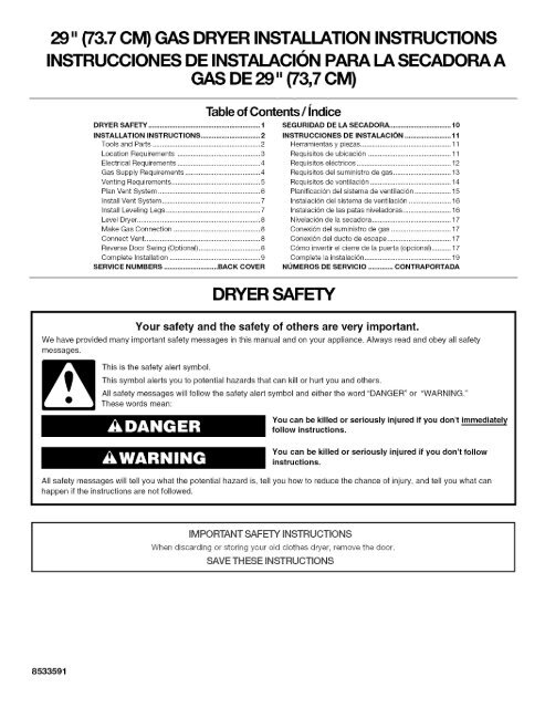
29" (73.7CM) GAS DRYER INSTALLATIONINSTRUCTIONS<br />
INSTRUCCIONES DE INSTALACION PARA LA SECADORA A<br />
GAS DE 29" (73,7CM)<br />
DRYER SAFETY .......................................................... 1<br />
INSTALLATION INSTRUCTIONS ............................... 2<br />
Tools and Parts ........................................................ 2<br />
Location Requirements ........................................... 3<br />
Electrical Requirements ........................................... 4<br />
Gas Supply Requirements ....................................... 4<br />
Venting Requirements .............................................. 5<br />
Plan Vent System ..................................................... 6<br />
Install Vent System ................................................... 7<br />
Install Leveling Legs ................................................. 7<br />
Level Dryer ................................................................ 8<br />
Make Gas Connection ............................................. 8<br />
Connect Vent ............................................................ 8<br />
Reverse Door Swing (Optional) ................................ 8<br />
Complete Installation ............................................... 9<br />
SERVICE NUMBERS ............................ BACK COVER<br />
Table of Contents/Jndice<br />
DRYER SAFETY<br />
SEGURIDAD DE LA SECADORA ................................ 10<br />
INSTRUCCION ES DE INSTALACION ........................ 11<br />
Herramientas y piezas ............................................... 11<br />
Requisitos de ubicaci6n ........................................... 11<br />
Requisitos el6ctrioos ................................................. t 2<br />
Requisitos del suministro de <strong>gas</strong> .............................. 13<br />
Requisitos de ventilaci6n .......................................... 14<br />
Planificacion del sistema de ventilacion ................... 15<br />
Instalaci6n del sistema de ventilacion ...................... 16<br />
Instalaci6n de las patas niveladoras ......................... 16<br />
Nivelacion de la secadora ......................................... 17<br />
Conexion del suministro de <strong>gas</strong> ............................... 17<br />
Conexion del ducto de escape ................................. 17<br />
C6mo invertir el cierre de la puerta (opcional) .......... 17<br />
Complete la instalacion ............................................. 19<br />
NUMEROS DE SERVICIO ............. CONTRAPORTADA<br />
Your safety and the safety of others are very important.<br />
We have provided many important safety messages in this manual and on your appliance. Always read and obey all safety<br />
messages.<br />
This is the safety alert symbol.<br />
This symbol alerts you to potential hazards that can kill or hurt you and others.<br />
All safety messages will follow the safety alert symbol and either the word "DANGER" or "WARNING."<br />
These words mean:<br />
You can be killed or seriously injured if you don't immediately<br />
follow instructions.<br />
You can be killed or seriously injured if you don't follow<br />
instructions.<br />
All safety messages will tell you what the potential hazard is, tell you how to reduce the chance of injuw, and tell you what can<br />
happen if the instructions are not followed.<br />
8533591<br />
iMPORTANT SAFETY INSTRUCTIONS<br />
When discarding or storing your old clothes <strong>dryer</strong>, remove the door.<br />
SAVE THESE iNSTRUCTiONS
I WARNING: For your safety, the information in this manual must be followed to minimize<br />
the risk of fire or explosion, or to prevent property damage, personal injury, or death.<br />
- Do not store or use <strong>gas</strong>oline or other flammable vapors and liquids in the vicinity of this<br />
or any other appliance.<br />
- WHAT TO DO IF YOU SMELL GAS:<br />
• Do not try to light any appliance.<br />
• Do not touch any electrical switch; do not use any phone in your building.<br />
• Clear the room, building, or area of all occupants.<br />
• Immediately call your <strong>gas</strong> supplier from a neighbor's phone. Follow the <strong>gas</strong> supplier's<br />
instructions.<br />
• If you cannot reach your <strong>gas</strong> supplier, call the fire department.<br />
- Installation and service must be performed by a qualified installer, service agency, or<br />
the <strong>gas</strong> supplier.<br />
In the State of Massachusetts, the following installation instructions apply:<br />
= Installations and repairs must be performed by a qualified or licensed contractor, plumber, or <strong>gas</strong>fitter qualified or licensed by<br />
the State of Massachusetts.<br />
= If using a ball valve, it shall be a T-handle type.<br />
= A flexible <strong>gas</strong> connector, when used, must not exceed 3 feet.<br />
Check that you have everything necessary for correct installation.<br />
Proper installation is your responsibility.<br />
8" or 10" pipe wrench •<br />
8" or 10" adjustable<br />
wrench (for <strong>gas</strong> •<br />
connections) •<br />
Flat-blade screwdriver<br />
Adjustable wrench that<br />
opens to 1" (2.5 cm) or<br />
hex-head socket wrench<br />
(for adjusting <strong>dryer</strong> feet)<br />
Level<br />
INSTALLATION INSTRUCTIONS<br />
¼"nut driver orsocket<br />
wrench<br />
Knife<br />
Vent clamps<br />
Pipe-joint compound<br />
resistant to L.R <strong>gas</strong><br />
Caulking gun and<br />
compound (for installing<br />
new exhaust vent)<br />
Pliers<br />
Parts supplied:<br />
Remove parts package from <strong>dryer</strong> drum. Check that all parts<br />
were included.<br />
Parts needed:<br />
4 leveling legs<br />
Check local codes and with <strong>gas</strong> supplier, check existing <strong>gas</strong><br />
supply, electrical supply and venting, and read "Electrical<br />
Requirements," "Gas Supply Requirements" and "Venting<br />
Requirements" before purchasing parts.<br />
Mobile home installations require special parts (listed following)<br />
available for purchase from your local <strong>Sears</strong> store or <strong>Sears</strong><br />
Service Center. For further information, please call<br />
1-800-4-MY-HOME ® (1-800-46g-4663).<br />
• Mobile Home Installation Kit. Ask for Part Number 346764.<br />
• Metal exhaust system hardware.
Explosion Hazard<br />
Keep flammable materials and vapors, such as<br />
<strong>gas</strong>oline, away from <strong>dryer</strong>.<br />
Place <strong>dryer</strong> at meast 18 inches (46 cm) above the floor<br />
for a garage installation°<br />
Failure to do so can result in death, e×plosion, or fire,<br />
You will need<br />
• A location that allows for proper exhaust installation. A <strong>gas</strong><br />
<strong>dryer</strong> must be exhausted to the outdoors. See "Venting<br />
Requirements."<br />
• A grounded electrical outlet located within 2 ft (61 cm) of<br />
either side of the <strong>dryer</strong>. See "Electrical Requirements•"<br />
• A sturdy floor to support the <strong>dryer</strong> with a total weight (<strong>dryer</strong><br />
and load) of 200 Ibs (90.7 kg). The combined weight of a<br />
companion appliance should also be considered•<br />
• A level floor with a maximum slope of 1" (2.5 cm) under entire<br />
<strong>dryer</strong>• (If slope is greater than 1" [2.5 cm], install Extended<br />
Dryer Feet Kit, Part Number 279810.) Clothes may not tumble<br />
properly and <strong>dryer</strong>s with automatic sensor cycles may not<br />
operate correctly if <strong>dryer</strong> is not level.<br />
Do not operate your <strong>dryer</strong> at temperatures below 45°F (7°C). At<br />
lower temperatures, the <strong>dryer</strong> might not shut off at the end of an<br />
automatic cycle. Drying times can be extended•<br />
The <strong>dryer</strong> must not be installed or stored in an area where it will<br />
be exposed to water and/or weather•<br />
Check code requirements• Some codes limit, or do not permit,<br />
installation of the <strong>dryer</strong> in garages, closets, mobile homes, or<br />
sleeping quarters• Contact your local building inspector.<br />
NOTE: No other fuel-burning appliance can be installed in the<br />
same closet as a <strong>dryer</strong>.<br />
Installation Clearances<br />
The location must be large enough to allow the <strong>dryer</strong> door to<br />
open fully.<br />
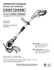
Dryer Dimensions<br />
43%<br />
(110cm<br />
C<br />
22%"<br />
(70a5Ct<br />
A. Small Opening Side-Swing Door<br />
B. Large Opening Side-Swing Door<br />
C. Wide Opening Side-Swing Door<br />
D. Wide Opening Hamper Door<br />
*Most installations require a minimum 51/2"(14 cm) clearance<br />
behind the <strong>dryer</strong> for the exhaust vent with elbow• See "Venting<br />
Requirements."<br />
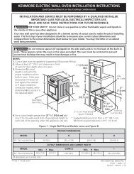
Minimum installation spacing for recessed area or closet<br />
installation<br />
The dimensions shown following are for the minimum spacing<br />
allowed•<br />
• Additional spacing should be considered for ease of<br />
installation and servicing.<br />
• Additional clearances might be required for wall, door and<br />
floor moldings.<br />
• Additional spacing of 1" (2.5 cm) on all sides of the <strong>dryer</strong> is<br />
recommended to reduce noise transfer.<br />
• For closet installation, with a door, minimum ventilation<br />
openings in the top and bottom of the door are required.<br />
Louvered doors with equivalent ventilation openings are<br />
acceptable.<br />
• Companion appliance spacing should also be considered.<br />
(453 cm)<br />
n<br />
olo<br />
24 ina2 -<br />
(155 cm 2)<br />
A. Recessed area<br />
B. Side view - closet or confined area<br />
C. Closet door with vents<br />
"_3"<br />
_'=6ore)<br />
-NNI<br />
cm)<br />
,I,
Mobile Home - Additional Installation Requirements<br />
This <strong>dryer</strong> is suitable for mobile home installations.<br />
The installation must conform to the Manufactured Home<br />
Construction and Safety Standard, Title 24 CFR, Part 3280<br />
(formerly the Federal Standard for Mobile Home Construction<br />
and Safety, Title 24, HUD Part 280).<br />
Mobile home installations require:<br />
• Metal exhaust system hardware which is available for<br />
purchase from your local <strong>Sears</strong> store or <strong>Sears</strong> Service dealer.<br />
• Mobile home Installation Kit Part Number 346764. See "Tools<br />
and Parts" section for ordering information.<br />
• Special provisions must be made in mobile homes to<br />
introduce outside air into the <strong>dryer</strong>. The opening (such as a<br />
nearby window) should be at least twice as large as the <strong>dryer</strong><br />
exhaust opening.<br />
Emectrica_ Shock Hazard<br />
Plug into a grounded 3 prong outlet.<br />
Do not remove ground prong.<br />
Do not use an adapter.<br />
Do not use an extension cord.<br />
Faimure to follow these instructions can resumt in death,<br />
fire, or emectrical shock.<br />
• 120-Volt, 60-Hz., AC-only, 15- or 20-amp, fused electrical<br />
supply is required. A time-delay fuse or circuit breaker is<br />
recommended. It is recommended that a separate circuit<br />
serving only this <strong>dryer</strong> be provided.<br />
IMPORTANT: The <strong>dryer</strong> must be electrically grounded in<br />
accordance with local codes, or in the absence of local codes,<br />
with the National Electrical Code, ANSl/NFPA 70.<br />
GROUNDING INSTRUCTIONS<br />
_=For a grounded, cord-connected <strong>dryer</strong>:<br />
This <strong>dryer</strong> must be grounded= In the event of malfunction or<br />
breakdown, grounding will reduce the risk of electric shock<br />
by providing a path of least resistance for electric current=<br />
This <strong>dryer</strong> is equipped with a cord having an equipmentgrounding<br />
conductor and a grounding plug= The plug must<br />
be plugged into an appropriate outlet that is properly<br />
installed and grounded in accordance with all local codes<br />
and ordinances.<br />
WARNING; Improper connection of the equipmentgrounding<br />
conductor can result in a risk of electric shock=<br />
Check with a qualified electrician or service representative<br />
or personnel if you are in doubt as to whether the <strong>dryer</strong> is<br />
properiy grounded= Do not modify the plug provided with the<br />
<strong>dryer</strong>: if it will not fit the outlet, have a proper outlet installed<br />
by a qualified electrician=<br />
SAVE THESE iNSTRUCTiONS<br />
Explosion Hazard<br />
Use a new AGA or CSA approved <strong>gas</strong> supply mine.<br />
Install a shut-off vatveo<br />
SecureSy tighten all <strong>gas</strong> connections.<br />
ff connected to LP, have a qualified person make sure<br />
<strong>gas</strong> pressure does not exceed 13" (33 cm) water<br />
comumno<br />
Exampmes of a quamified person include:<br />
licensed heating personnel,<br />
authorized <strong>gas</strong> company personnel, and<br />
authorized service personnel.<br />
Failure to do so can result in death, explosion, or fire.<br />
Gas Type<br />
Natural Gas:<br />
This <strong>dryer</strong> is equipped for use with natural <strong>gas</strong>. It is designcertified<br />
by CSA International for L.R (propane or butane) <strong>gas</strong>es<br />
with appropriate conversion.<br />
• Your <strong>dryer</strong> must have the correct burner for the type of <strong>gas</strong> in<br />
your home. Burner information is located on the rating plate<br />
in the door well of your <strong>dryer</strong>. If this information does not<br />
agree with the type of <strong>gas</strong> available, contact your local <strong>Sears</strong><br />
store or <strong>Sears</strong> Service Center.<br />
L.P. <strong>gas</strong> conversion:<br />
Conversion must be made by a qualified technician.<br />
No attempt shall be made to convert the appliance from the <strong>gas</strong><br />
specified on the model/serial rating plate for use with a different<br />
<strong>gas</strong> without consulting the serving <strong>gas</strong> supplier.<br />
IMPORTANT: The <strong>gas</strong> installation must conform with local<br />
codes, or in the absence of local codes, with the National Fuel<br />
Gas Code, ANSI Z223.1/NFPA 54.<br />
Gas Supply Line:<br />
• 1/2"IPS pipe is recommended.<br />
• %" approved tubing is acceptable for lengths under 20 ft<br />
(6.1 m) if local codes and <strong>gas</strong> supplier permit.<br />
• Must include Vs"NPT minimum plugged tapping accessible<br />
for test gauge connection, immediately upstream of the <strong>gas</strong><br />
connection to the <strong>dryer</strong> (see illustration).
• Mustincludeashutoffvalve:<br />
Anindividual manual shutoffvalvemustbeinstalledwithinsix<br />
(6)feet(1.8m)ofthe<strong>dryer</strong>inaccordance withtheNational<br />
FuelGasCode,ANSIZ223.1. Thelocationshouldbeeasyto<br />
reachforopeningandclosing.<br />
A C E<br />
B D<br />
A. _" flexible <strong>gas</strong> connector<br />
B. _" pipe to flare adapter fitting<br />
C. _" NPT plugged tapping<br />
D. V2" NPT <strong>gas</strong> supply line<br />
E. Gas shutoff valve<br />
Gas supply connection requirements<br />
There are many methods by which your <strong>gas</strong> <strong>dryer</strong> can be<br />
connected to the <strong>gas</strong> supply. Listed here are some guidelines for<br />
two different methods of connection.<br />
Option 1 (Recommended Method)<br />
Flexible stainless steel <strong>gas</strong> connector:<br />
• If local codes permit, use a new flexible stainless steel <strong>gas</strong><br />
connector (Design Certified by the American Gas Association<br />
or CSA International) to connect your <strong>dryer</strong> to the rigid <strong>gas</strong><br />
supply line. Use an elbow and a %" flare x %" NPT adapter<br />
fitting between the stainless steel <strong>gas</strong> connector and the<br />
<strong>dryer</strong> <strong>gas</strong> pipe, as needed to prevent kinking.<br />
Option 2 (Alternate Method)<br />
Approved aluminum or copper tubing:<br />
• Lengths under 20 ft (6.1 m) can use %" approved tubing (if<br />
codes and <strong>gas</strong> supplier permit).<br />
• If you are using natural <strong>gas</strong>, do not use copper tubing.<br />
• %" flare x %" NPT adapter fitting between <strong>dryer</strong> pipe and %"<br />
approved tubing.<br />
• Lengths over 20 ft (6.1 m) should use larger tubing and a<br />
different size adapter fitting.<br />
• If your <strong>dryer</strong> has been converted to use LR <strong>gas</strong>, %" L.R<br />
compatible copper tubing can be used. If the total length of<br />
the supply line is more than 20 ft (6.1 m), use larger pipe.<br />
NOTE: Pipe joint compounds that resist the action of L.R <strong>gas</strong><br />
must be used. Do not use TEFLON °t tape.<br />
Dryer Gas Pipe<br />
• The <strong>gas</strong> pipe that comes out through the rear of your <strong>dryer</strong><br />
has a %" male pipe thread.<br />
(23.5om)<br />
A._"NPTd_erp_e<br />
jl<br />
11_ _,<br />
(3.2cm)<br />
t®TEFLON is a registered trademark of E.I. Du Pont De Nemours and Company.<br />
Burner Input Requirements:<br />
Elevations up to 10,000 ft (3,048 meters):<br />
• The design of this <strong>dryer</strong> is certified by CSA International for<br />
use at altitudes up to 10,000 ft (3,048 m) above sea level at<br />
the B.T.U. rating indicated on the model/serial number plate.<br />
Burner input adjustments are not required when the <strong>dryer</strong> is<br />
operated up to this elevation.<br />
Elevations above 10,000 ft (3,048 meters):<br />
• When installed above 10,000 ft (3,048 m) a 4% reduction of<br />
the burner B.T.U. rating shown on the model/serial number<br />
plate is required for each 1,000 ft (305 m) increase in<br />
elevation.<br />
Gas Supply Pressure Testing<br />
• The <strong>dryer</strong> must be disconnected from the <strong>gas</strong> supply piping<br />
system during pressure testing at pressures greater than<br />
1/2psi.<br />
Use a heavy metal vent.<br />
Do not use a plastic vent.<br />
Do not use a metal foimvent.<br />
Fire Hazard<br />
FaUure to follow these instructions can resumt in death<br />
or fire.<br />
WARNING; To reduce the risk of fire, this <strong>dryer</strong> MUST BE<br />
EXHAUSTED OUTDOORS.<br />
4" (10.2 cm) heavy metal exhaust vent and clamps must be used.<br />
DURASAFE TM venting products are recommended.<br />
DURASAFE TM vent products can be purchased from your local<br />
<strong>Sears</strong> store or <strong>Sears</strong> Service Center. For more information, call<br />
1-800-4-MY-HOME ® (1-800-469-4663).<br />
• The <strong>dryer</strong> exhaust must not be connected into any <strong>gas</strong> vent,<br />
chimney, wall, ceiling, or a concealed space of a building.<br />
• Do not use an exhaust hood with a magnetic latch.<br />
• Do not install flexible metal vent in enclosed walls, ceilings or<br />
floors.
• Use clamps to seal all joints. Exhaust vent must not be<br />
connected or secured with screws or other fastening devices<br />
which extend into the interior of the duct. Do not use duct<br />
tape.<br />
IMPORTANT: Observe all governing codes and ordinances.<br />
improper venting can cause moisture and lint to collect<br />
indoors, which may resumt in:<br />
[] Moisture damage to woodwork, furniture, paint,<br />
wa!lpaper, carpets, etc.<br />
[] Housecleaning problems and health problems.<br />
Use a heavy metal vent. Do not use plastic or metal foil vent.<br />
Rigid metal vent is recommended to prevent crushing and kinking.<br />
Flexible metal vent must be fully extended and supported when<br />
the <strong>dryer</strong> is in its final position. Remove excess flexible metal vent<br />
to avoid sagging and kinking that may result in reduced airflow<br />
and poor performance.<br />
An exhaust hood should cap the vent to prevent rodents and<br />
insects from entering the home.<br />
Exhaust hood must be at least 12" (30.5 cm) from the ground or<br />
any object that may be in the path of the exhaust (such as<br />
flowers, rocks or bushes, etc.).<br />
If using an existing vent system, clean lint from the entire length<br />
of the system and make sure exhaust hood is not plugged with<br />
lint. Replace any plastic or metal foil vent with rigid metal or<br />
flexible metal vent.<br />
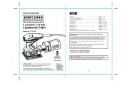
Typical exhaust installations<br />
Typical installations vent the <strong>dryer</strong> from the rear of the <strong>dryer</strong>.<br />
A ............<br />
A. Dryer<br />
B. Elbow<br />
C. Wall<br />
D. Exhaust hood<br />
E-- E<br />
B<br />
E, Clamps<br />
F. Rigid metal or flexible metal vent<br />
G. Vent length necessary to connect<br />
elbows<br />
H. Exhaust outlet<br />
Standard exhaust installation with rigid metal or flexible<br />
metal vent<br />
Alternate installations for close clearances<br />
Venting systems come in many varieties. Select the type best for<br />
your installation. Two close-clearance installations are shown.<br />
Refer to the manufacturer's instructions.<br />
A B<br />
A. Over-The-Top installation (also available with one offset<br />
elbow)<br />
B. Periscope installation<br />
NOTE: The following kits for close clearance alternate<br />
installations are available for purchase. For further information,<br />
please call 1-800-4-MY-HOME ®(1-800-469-4663).<br />
• Over-The-Top Installation:<br />
Part Number 26-49900<br />
Periscope Installation (For use with <strong>dryer</strong> vent to wall vent<br />
mismatch):<br />
Part Number 26-49901 - Less than 5" (12.7 cm) mismatch<br />
Part Number 26-49908 - 5" (12.7 cm) to 18" (45.72 cm)<br />
mismatch<br />
Part Number 26-49904 - 18" (45.72 cm) to 29" (73.66 cm)<br />
mismatch<br />
Part Number 26-49905 - 29" (73.66 cm) to 50" (127 cm)<br />
mismatch<br />
Special provisions for mobile home installations<br />
The exhaust vent must be securely fastened to a noncombustible<br />
portion of the mobile home structure and must not terminate<br />
beneath the mobile home. Terminate the exhaust vent outside.<br />
S
Determine Vent Length<br />
1. Select the route that will provide the straightest and most<br />
direct path outdoors. Plan the installation to use the fewest<br />
number of elbows and turns. When using elbows or making<br />
turns, allow as much room as possible. Bend vent gradually<br />
to avoid kinking. Avoid 90 ° turns when possible.<br />
2. Determine vent length<br />
3=<br />
The maximum length of the exhaust system depends upon:<br />
• The type of vent (rigid metal or flexible metal).<br />
• The number of elbows used.<br />
• Type of hood.<br />
Recommended hood styles are shown here.<br />
(10.2cm)<br />
A. Louvered hood style<br />
B. Box hood style<br />
The angled hood style (shown following) is acceptable.<br />
See the exhaust vent length chart that matches your hood<br />
type for the maximum vent lengths you can use.<br />
Exhaust systems longer than specified will:<br />
• Shorten the life of the <strong>dryer</strong>.<br />
• Reduce performance, resulting in longer drying times and<br />
increased energy usage.<br />
Determine the number of elbows you will need.<br />
IMPORTANT: Do not use vent runs longer than specified in<br />
the Vent Length Chart.<br />
The following chart helps you determine your maximum vent<br />
length based on the number of 90 ° turns or elbows you will<br />
need and the type of vent (rigid or flexible metal) and hood<br />
that you will use.<br />
Vent Length Chart<br />
Number of Type of Box or Angled<br />
90 ° turns vent Louvered hoods<br />
or elbows hoods<br />
0 Rigid metal 64 ft (20 m) 58 ft (17.7 m)<br />
Flexible metal 36 ft (11 m) 28 ft (8.5 m)<br />
1 Rigid metal 54 ft (16.5 m) 48 ft (14.6 m)<br />
Flexible metal 31 ft (9.4 m) 23 ft (7 m)<br />
2 Rigid metal 44 ft (13.4 m) 38 ft (11.6 m)<br />
Flexible metal 27 ft (8.2 m) 19 ft (5.8 m)<br />
3 Rigid metal 35 ft (10.7 m) 29 ft (8.8 m)<br />
Flexible metal 25 ft (7.6 m) 17 ft (5.2 m)<br />
4 Rigid metal 27 ft (8.2 m) 21 ft (6.4 m)<br />
Flexible metal 23 ft (7 m) 15 ft (4.6 m)<br />
1. Install exhaust hood. Use caulking compound to seal exterior<br />
wall opening around exhaust hood.<br />
2. Connect vent to exhaust hood. Vent must fit inside exhaust<br />
hood. Secure vent to exhaust hood with 4" (10.2 cm) clamp.<br />
3. Run vent to <strong>dryer</strong> location. Use the straightest path possible.<br />
See "Determine Vent Length." Avoid 90 ° turns. Use clamps to<br />
seal all joints. Do not use duct tape, screws or other fastening<br />
devices that extend into the interior of the vent to secure<br />
vent.<br />
1. To protect the floor, use a large flat piece of cardboard from<br />
the <strong>dryer</strong> carton. Place cardboard under the entire back edge<br />
of the <strong>dryer</strong>. See illustration.<br />
2. Firmly grasp the body of the <strong>dryer</strong> (not the top or console<br />
panel). Gently lay the <strong>dryer</strong> on the cardboard.<br />
3. Examine the leveling legs. Find the diamond marking.<br />
4. Screw the legs into the leg holes by hand. Use a wrench to<br />
finish turning the legs until the diamond marking is no longer<br />
visible.
5. Placeacartoncornerpostundereachofthe2<strong>dryer</strong>back<br />
corners. Standthe<strong>dryer</strong>up.Slidethe<strong>dryer</strong>onthecorner<br />
postsuntilit isclosetoitsfinalocation. Leavenoughroom<br />
toconnect theexhaust vent.<br />
6. Onceconnection ismadeand<strong>dryer</strong>isinfinalocation,<br />
removecornerpostsandcardboard.<br />
For mobile home use<br />
Gas <strong>dryer</strong>s must be securely fastened to the floor.<br />
Mobile home installations require a Mobile Home Installation Kit.<br />
See "Tools and Parts" section for ordering information.<br />
Check the levelness of the <strong>dryer</strong>. Check levelness first<br />
side to side, then front to back.<br />
If the <strong>dryer</strong> is not level, prop up the <strong>dryer</strong> using a wood block.<br />
Use a wrench to adjust the legs up or down and check again for<br />
levelness.<br />
NOTE: It might be necessary to level the <strong>dryer</strong> again after it is<br />
moved into its final position.<br />
1=<br />
2.<br />
Remove the red cap from the <strong>gas</strong> pipe. Move the <strong>dryer</strong> close<br />
to its final position.<br />
Using a wrench to tighten, connect the <strong>gas</strong> supply to the<br />
<strong>dryer</strong>. Use pipe joint compound on all non-flared male<br />
threads. If flexible metal tubing is used, be sure there are no<br />
kinks.<br />
NOTE: For L.R <strong>gas</strong> connections, you must use pipe joint<br />
compound resistant to the action of LR <strong>gas</strong>. Do not use<br />
TEFLON ®ttape.<br />
A combination of pipe fittings must be used to connect the<br />
<strong>dryer</strong> to the existing <strong>gas</strong> line. Shown following is a<br />
recommended connection. Your connection may be different,<br />
according to the supply line type, size, and location.<br />
A. _" flexible <strong>gas</strong> connector<br />
B. _" <strong>dryer</strong>pipe<br />
C. _" to _" pipe elbow<br />
D. _" pipe-to-flare adapter fitting<br />
!<br />
C<br />
3. Open the shutoff valve in the supply line. The valve is open<br />
when the handle is parallel to the <strong>gas</strong> pipe.<br />
A. Closed valve<br />
B. Open valve<br />
Test all connections by brushing on an approved<br />
noncorrosive leak-detection solution. Bubbles will show<br />
a leak. Correct any leak found.<br />
1. Using a 4" (10.2 cm) clamp, connect vent to exhaust outlet in<br />
<strong>dryer</strong>. If connecting to existing vent, make sure the vent is<br />
clean. The <strong>dryer</strong> vent must fit over the <strong>dryer</strong> exhaust outlet<br />
and inside the exhaust hood. Make sure the vent is secured<br />
to exhaust hood with a 4" (10.2 cm) clamp.<br />
2. Move <strong>dryer</strong> into final position. Do not crush or kink vent.<br />
Make sure <strong>dryer</strong> is level.<br />
3. (On <strong>gas</strong> models) Check to be sure there are no kinks in the<br />
flexible <strong>gas</strong> line.<br />
You can change your door swing from a right-side opening to a<br />
left-side opening, if desired.<br />
Reversible Large Side-Swing Door<br />
1. Place towel (A) on top of <strong>dryer</strong> to protect surface.<br />
2. Open <strong>dryer</strong> door. Remove bottom screws from cabinet side<br />
of hinges (C). Loosen (do not remove) top screws from<br />
cabinet side of hinges.<br />
3. Lift door until top screws in cabinet are in large part of hinge<br />
slot. Pull door forward off screws. Set door on top of <strong>dryer</strong>.<br />
Remove top screws from cabinet.<br />
4. Use a small, flat-blade screwdriver to carefully remove<br />
4 hinge hole plugs (D) on left side of cabinet. Insert plugs in<br />
hinge holes on right side of cabinet.<br />
5. Insert screws in bottom holes on left side of cabinet. Tighten<br />
screws halfway. Position door so large end of door hinge slot<br />
is over screws. Slide door up so screws are in bottom of<br />
slots. Tighten screws. Insert and tighten top screws in hinges.
6. Closedoorandcheckthatdoorstrikealignswithdoorcatch<br />
(B).Ifneeded, slidedoorcatchleftorrightwithinsloto<br />
adjustalignment.<br />
Reversible Super Wide Side-Swing Door<br />
1. Place towel (A) on top of <strong>dryer</strong> to protect surface.<br />
} C<br />
2. Open <strong>dryer</strong> door. Remove bottom screws from cabinet side<br />
of hinges (D). Loosen (do not remove) top screws from<br />
cabinet side of hinges.<br />
3. Lift door until top screws in cabinet are in large part of hinge<br />
slot. Pull door forward off screws. Set door (handle side up)<br />
on top of <strong>dryer</strong>. Remove top screws from cabinet.<br />
4. Remove screws attaching hinges to door.<br />
5. Remove screws at top, bottom and side of door (4 screws).<br />
Holding door over towel on <strong>dryer</strong>, grasp sides of outer door<br />
and carefully lift to separate it from inner door. Do not pry<br />
apart with putty knife. Do not pull on door seal or plastic door<br />
catches.<br />
6. Be careful to keep cardboard spacer centered between<br />
doors. Reattach outer door panel to inner door panel so<br />
handle is on the side where hinges were just removed.<br />
7= Attach door hinges to door so large part of hinge slot is at<br />
bottom of hinge.<br />
D<br />
8. Remove door strike (E) from cabinet. Use a small, flat-blade<br />
screwdriver to carefully remove 4 hinge hole plugs (F) on left<br />
side of cabinet. Insert plugs in hinge holes on right side of<br />
cabinet.<br />
9. Insert screws in bottom holes on left side of cabinet. Tighten<br />
screws halfway. Position door so large end of door hinge slot<br />
is over screws. Slide door up so screws are in bottom of<br />
slots. Tighten screws. Insert and tighten top screws in hinges.<br />
10. Remove door strike plug (B). Insert the door strike you<br />
removed in Step 8 in hole and secure with screw. Insert door<br />
strike plug in original door strike hole and secure with screw.<br />
11. Close door and check that door strike aligns with door catch<br />
(C). If needed, slide door catch left or right within slot to<br />
adjust alignment.<br />
2=<br />
3.<br />
4.<br />
5=<br />
6.<br />
7.<br />
8=<br />
g.<br />
10.<br />
11.<br />
Check to be sure all parts are now installed. If there is an<br />
extra part, go back through the steps to see which step was<br />
skipped.<br />
Check to be sure you have all of your tools.<br />
Dispose of all packaging materials.<br />
Check the <strong>dryer</strong>'s final location. Be sure the vent is not<br />
crushed or kinked.<br />
Check to be sure the <strong>dryer</strong> is level. See "Level Dryer."<br />
Plug into a grounded 3 prong outlet. Turn power on.<br />
Remove the blue protective film on the console and any tape<br />
remaining on the <strong>dryer</strong>.<br />
Read your "Dryer User Instructions."<br />
Wipe the <strong>dryer</strong> drum interior thoroughly with a damp cloth to<br />
remove any dust.<br />
Set the <strong>dryer</strong> on a full heat cycle (not an air cycle) for<br />
20 minutes and start the <strong>dryer</strong>.<br />
If the <strong>dryer</strong> will not start, check the following:<br />
• Dryer is plugged into a grounded 3 prong outlet.<br />
• Electrical supply is connected.<br />
• House fuse is intact and tight, or circuit breaker has not<br />
tripped.<br />
• Dryer door is closed.<br />
When the <strong>dryer</strong> has been running for 5 minutes, open the<br />
<strong>dryer</strong> door and feel for heat. If you do not feel heat, turn the<br />
<strong>dryer</strong> off and check to see whether <strong>gas</strong> supply line shutoff<br />
valve is open.<br />
• If the <strong>gas</strong> supply line shutoff valve is closed, open it, then<br />
repeat the 5-minute test as outlined above.<br />
• If the <strong>gas</strong> supply line shutoff valve is open, contact a<br />
qualified technician.
10<br />
INSTRUCCIONES DE INSTALACION PARA LA SECADORA A<br />
GAS DE 29" (73,7 CM)<br />
SEGURIDAD DE LA SECADORA<br />
Su seguridad y la seguridad de los demas es muy importante.<br />
Hemos incluido muchos mensajes importantes de seguridad en este manual yen su electrodomestico. Lea y obedezca siempre<br />
todos los mensajes de seguridad=<br />
Este sfmbolo le llama la atencion<br />
usted y a los dem_.s.<br />
sobre peligros potenciales que pueden ocasionar la muerte o una lesion a<br />
Este Todoseslos el sfmbolo mensajesdedeadvertencia seguridad de iranseguridad. a continuacidn del simbolo de advertencia de seguridad y de la palabra<br />
"PELIGRO" o "ADVERTENCIA". Estas palabras significan:<br />
Si no sigue las <strong>instrucciones</strong> de inmediato, usted puede<br />
morir o sufrir una lesion grave.<br />
Si no sigue las <strong>instrucciones</strong>, usted puede morir o sufrir<br />
una lesion grave.<br />
Todos los mensajes de seguridad le diran el peligro potencial, le diran como reducir las posibilidades de sufrir una lesion y Io que<br />
puede suceder si no se siguen las <strong>instrucciones</strong>.<br />
iNSTRUCCiONES iMPORTANTES DE SEGURiDAD<br />
Antes de guardar o descartar su vieja secadora, qdtele la puerta=<br />
GUARDE ESTAS INSTRUCCIONES<br />
ADVERTENCIA: Para su seguridad, la informacibn en este manual debe ser observada<br />
para minimizar el riesgo de incendio o explosibn, o para prevenir dahos a propiedades,<br />
heridas o la muerte.<br />
- No almacene o use <strong>gas</strong>olina u otros liquidos y vapores inflamables cerca de _ste u otro<br />
aparato electrodom_stico.<br />
- PASOS QUE USTED DEBE SEGUIR SI HUELE A GAS:<br />
• No trate de encender ning0n aparato electrodom_stico.<br />
• No toque ning0n interruptor el_ctrico; no use ningOn tel_fono en su edificio.<br />
• Desaloje a todos los ocupantes del cuarto, edificio o area.<br />
• Llame inmediatamente a su proveedor de <strong>gas</strong> desde el tel_fono de un vecino.<br />
Siga las <strong>instrucciones</strong> de su proveedor de <strong>gas</strong>.<br />
• Si usted no puede comunicarse con su proveedor de <strong>gas</strong>, Ilame al departamento<br />
de bomberos.<br />
- La instalacibn y el servicio deben ser efectuados por un instalador calificado, una<br />
agencia de servicio o por el proveedor de <strong>gas</strong>.
En el estado de Massachusetts se apIican Ias siguientes <strong>instrucciones</strong> de instalaci6n:<br />
• Las instalaciones y reparaciones se deben efectuar per un contratista, plomero o <strong>gas</strong>ista calificado o licenciado per el estado<br />
de Massachusetts.<br />
• Si se usa una valvula de bola, debe ser un tipo de manigueta T.<br />
• Si se usa un conector de <strong>gas</strong> flexible no debe exceder de 3 pies.<br />
INSTRUCCIONES DE INSTALACION<br />
Verifique si tiene todo Io necesario para una instalaci6n correcta.<br />
La instalaci6n adecuada es responsabilidad suya.<br />
Llave para tubes de 8" 6 •<br />
10"<br />
Llave de tuercas<br />
ajustable de 8" 6 10"<br />
Nivel<br />
Llave de tuercas<br />
ajustable que se abra a •<br />
1" (2,5 cm) 0 una Ilave de<br />
cubo de cabeza<br />
hexagonal (para regular<br />
las patas de la secadora) • Alicates<br />
Llave para tuercas de v4"<br />
0 Ilave de cubo<br />
(para conexiones de <strong>gas</strong>) • Cuchillo<br />
Destornillador de hoja •<br />
Abrazaderas para ducto<br />
plana • Pegamento para tubefias<br />
resistente a <strong>gas</strong> L.R<br />
Piezas suministradas:<br />
Pistola y masilla para<br />
calafateo (para instalar el<br />
nuevo ducto de escape)<br />
Retire el paquete de piezas del tambor de la secadora. Verifique<br />
que esten todas las piezas.<br />
4 patas niveladoras<br />
Piezas para adquirir:<br />
Verifique los c6digos locales y con la compah[a abastecedora de<br />
<strong>gas</strong>, verifique el suministro de <strong>gas</strong> existente, el suministro<br />
electrico y la ventilaci6n y lea "Requisitos electricos", "Requisites<br />
de suministro de <strong>gas</strong>" y "Requisites de ventilaci6n" antes de<br />
comprar las piezas.<br />
Las instalaciones en casas rodantes requieren piezas especiales<br />
(enlistadas a continuaci6n) disponibles para la compra en su<br />
tienda local de <strong>Sears</strong> o en un Centre de servicio <strong>Sears</strong>. Para mas<br />
informaci6n, Ilame per favor al 1-800-4-MY-HOME ®<br />
(1-800-469-4663}.<br />
• Juego de instalaci6n para casas rodantes. Pida la pieza<br />
nQmero 346764.<br />
• Herramientas para el sistema de ventilaci6n de metal.<br />
PeBigrode Exploei6n<br />
Mantenga moemateriaBes y vapores infiamabies, como<br />
Bagaeomina, mejoe de maeecadorao<br />
CoBoque la secadora a un m[nimo de 46 cm eobre<br />
el pieo para la instalaci6n en un garaje°<br />
No eeguir estae inetruccionee puede ocaeionar<br />
la muerte, explosi6n o incendio.<br />
Usted necesitara<br />
• Una ubicaci6n que permita una instalaci6n adecuada del<br />
ducto de escape. La secadora a <strong>gas</strong> debe tener una salida de<br />
ventilaci6n hacia el exterior. Consulte "Requisitos de<br />
ventilaci6n".<br />
• Un contacto con conexi6n a tierra ubicado a un maximo de<br />
2 pies (61 cm) de cualquiera de los lades de la secadora. Vea<br />
"Requisitos electricos".<br />
• Un piso resistente para soportar la secadora con un peso<br />
total (secadora y carga) de 200 Ibs (90,7 kg). Asimismo se<br />
debe considerar el peso de otro artefacto que la acompahe.<br />
• Un piso nivelado con un declive maximo de 1" (2,5 cm)<br />
debajo de la secadora completa. (Si el declive es mayor que<br />
1" [2,5 cm], instale el Juego de extensi6n de patas de la<br />
secadora, Pieza nt_mero 279810.) La ropa quizas no rote<br />
adecuadamente y los ciclos del sensor automatico<br />
posiblemente no funcionen debidamente si la secadora no<br />
esta nivelada.<br />
No ponga a funcionar su secadora a temperaturas inferiores a<br />
45°F (7°C). A temperaturas inferiores, es posible que la secadora<br />
no se apague al final de un ciclo automatico. Los tiempos de<br />
secado pueden prolongarse.<br />
No debe instalarse ni guardarse la secadora en un Area en donde<br />
pueda estar expuesta al agua y/o a la intemperie.<br />
Verifique los requisitos de los c6digos. Algunos c6digos limitan, o<br />
no permiten, la instalaci6n de la secadora en garajes, cl6sets,<br />
casas rodantes o en dormitories. P6n<strong>gas</strong>e en contacto con el<br />
inspector de construcciones de su Iocalidad.<br />
NOTA: No se puede instalar otro electrodomestico que use<br />
combustible en el mismo cl6set en que se encuentra la secadora.<br />
11
Espacios para la instalacibn<br />
La ubicaci6n debe ser Io suficientemente grande para poder abrir<br />
completamente la puerta de la secadora.<br />
Dimensiones de la secadora<br />
43%<br />
(110cm/<br />
.27 _A_,_ -<br />
A<br />
(73,66crn)<br />
B<br />
A. Puerta chica de apertura lateral<br />
B. Puerta grande de apertura lateral<br />
C. Puerta ancha de apertura lateral<br />
D. Puerta ancha de apertura vertical<br />
D<br />
• i<br />
*La mayoria de las instalaciones requieren un espacio mfnimo de<br />
51/2'' (14 cm) detras de la secadora para acomodar el ducto de<br />
escape con codo. Vea "Requisites de ventilaci6n".<br />
Espacio minimo para la instalaci6n en un lugar empotrado o<br />
en un cl6set<br />
Las siguientes dimensiones ilustradas son para el espacio<br />
mfnimo permitido.<br />
• Debe considerarse el espacio adicional para facilitar la<br />
instalaci6n y el servicio tecnico.<br />
• Se podrian necesitar espacios libres adicionales para la<br />
pared y las molduras de la puerta y del piso.<br />
• Se recomienda un espacio adicional de 1" (2,5 cm) en todos<br />
los lados de la secadora para reducir la transferencia de<br />
ruido.<br />
12<br />
Para la instalaci6n en cl6set, con una puerta, se requieren<br />
aberturas de ventilaci6n mfnimas en la parte superior e<br />
inferior de la puerta. Se aceptan puertas tipo persianas con<br />
aberturas de ventilaci6n equivalentes.<br />
• Tambien se debe considerar espacio adicional para otro<br />
electrodomestico que le acompa_e.<br />
18"-/F<br />
(45,7crn)<br />
It<br />
o,o 48p0,g. _<br />
(310 cm2)<br />
24 puUg.2-<br />
.__ (155crn2}<br />
1"--_ _ 29" _ _-1" ÷11"1
IMPORTANTE: La secadora debe estar conectada a tierra de<br />
acuerdo con los c6digos locales, o si no los hay, con el C6digo<br />
Nacional de Electricidad (National Electrical Code),<br />
ANSI/NFPA 70.<br />
INSTRUCCIONES PARA LA CONEXION ATIERRA<br />
_' Para la conexi6n de una secadora mediante cable<br />
el6ctr[co conectado a t[erra:<br />
Esta secadora debe estar conectada a t[erra. En el caso de<br />
funcionamiento defectuoso o aver[a, Ia conexi6n a tierra<br />
reduc[rA el r[esgo de choque eIectr[co al proporcionar una<br />
via de menor res[stencia para la corriente electrica. Esta<br />
secadora esta equipada con un cable que cuenta con un<br />
conductor para Ia conex[6n a tierra del equipo y un enchufe<br />
de conexi6n a tierra. EI enchufe debe conectarse en un<br />
contacto apropiado, que este debidamente instaiado y<br />
conectado a tierra de acuerdo con todos los c6digos y<br />
ordenanzas Jocales.<br />
ADVERTENCJA: ha conexi6n indebida del<br />
conductor para Ia conex[6n a t[erra del equipo puede<br />
ocas[onar un r[esgo de choque electrico. Verif[que con un<br />
electricista, representante o persona! de servicio tecnico<br />
calificado para asegurarse de que Ia conex[6n a tierra de la<br />
secadora sea apropiada. No modifique ei enchufe<br />
proporcionado con la secadora. S[ no encaja en et contacto,<br />
contrate un electricista cal[ficado para que instale un<br />
contacto adecuado.<br />
GUARDE ESTAS INSTRUCCIONES<br />
Peligro de Explosi6n<br />
Usa una linea de suministro de <strong>gas</strong> nueva con<br />
aprobaci6n AGA o CSA.<br />
Instale una vamvumade cierre.<br />
Apdete firmemente todas las conexiones de <strong>gas</strong>.<br />
S[ se conecta a un suministro de <strong>gas</strong> L.P., [a presi6n no<br />
debe exceder una cotumna de agua de 33 cm (13 pulg.)<br />
y debe set verfficada por una persona calificada.<br />
Ejempmos de urea persona calificada incluyen:<br />
personam de servicio det sistema de camefacci6n con<br />
micencia,<br />
personam autorizado de macompa_a de <strong>gas</strong>, y<br />
personam autorizado para dar servicio.<br />
No seguir estas <strong>instrucciones</strong> puede ocasionar<br />
mamuerte, explosi6n o incendio.<br />
Tipo de <strong>gas</strong><br />
Gas natural:<br />
Esta secadora esta equipada para uso con <strong>gas</strong> natural. Su<br />
diseSo esta certificado por la CSA Internacional para <strong>gas</strong>es L.R<br />
(de propano o butano) con la conversi6n apropiada.<br />
• Su secadora debe tenet el quemador adecuado para el tipo<br />
de <strong>gas</strong> que tiene en su casa. La informaci6n respecto al<br />
quemador esta ubicada en la placa de clasificaci6n que esta<br />
en la cavidad de la puerta de su secadora. Siesta<br />
informaci6n no esta de acuerdo con el tipo de <strong>gas</strong> disponible,<br />
p6n<strong>gas</strong>e en contacto con su tienda <strong>Sears</strong> o con el Centro de<br />
Servicio <strong>Sears</strong> de su Iocalidad.<br />
Conversi6n de <strong>gas</strong> LP.:<br />
La conversi6n debera Ilevarla a cabo un t_cnico calificado.<br />
No se debera hacer intento alguno para convertir el uso del <strong>gas</strong><br />
especificado en la placa de clasificaci6n del modelo/de la serie<br />
de este artefacto por el uso de un <strong>gas</strong> distinto sin consultar con<br />
el abastecedor de <strong>gas</strong>.<br />
IMPORTANTE: La instalaci6n de <strong>gas</strong> debe hacerse de acuerdo<br />
con los c6digos locales, o si no los hay, con el C6digo<br />
Nacional de Gas Combustible (National Fuel Gas Code),<br />
ANSI Z223.1/NFPA 54.<br />
Linea del suministro de <strong>gas</strong>:<br />
• Se recomienda un tubo IPS de 1/2".<br />
• Si los c6digos locales y el proveedor de <strong>gas</strong> Io permiten, es<br />
aceptable una tuberia aprobada de %" para longitudes<br />
menores a los 20 pies (6,1 m).<br />
• Debe incluir una derivaci6n tapada NTP de por los menos 1/8"<br />
accesible para la conexi6n del man6metro de prueba,<br />
inmediatamente arriba de la conexi6n de suministro de <strong>gas</strong> a<br />
la secadora (vea la ilustraci6n).<br />
• Debe incluir una valvula de cierre:<br />
Debe instalarse una valvula de cierre individual manual a una<br />
distancia de un maximo de seis (6) pies (1,8 m) de la<br />
secadora de acuerdo con el C6digo Nacional de Gas<br />
combustible (National Fuel Gas Code), ANSI Z223.1. La<br />
valvula debera ubicarse en un lugar donde se pueda alcanzar<br />
con facilidad )ara cerrarla y abrirla.<br />
A C E<br />
B D<br />
A. Conector de <strong>gas</strong> flexible de ¾"<br />
B. Accesorio adaptador abocinado de ¾"<br />
C. Derivacidn tapada NPT de V8"<br />
D. Lfnea de suministro de <strong>gas</strong> NPT de F2"<br />
E. Vblvula de cierre del <strong>gas</strong><br />
Requisitos para la conexi6n del surninistro de <strong>gas</strong><br />
Existen muchos metodos mediante los cuales puede conectar su<br />
secadora a <strong>gas</strong> al suministro de <strong>gas</strong>. He aqui algunas directivas<br />
para dos metodos diferentes de conexidn.<br />
Opci6n 1 (M_todo recomendado)<br />
Conector de <strong>gas</strong> flexible de acero inoxidable:<br />
• Si los c6digos locales Io permiten, use un conector de <strong>gas</strong><br />
flexible nuevo de acero inoxidable (diser3o certificado por la<br />
Asociaci6n americana de <strong>gas</strong> o la CSA Internacional) para<br />
conectar su secadora a la I[nea r[gida de suministro de <strong>gas</strong>.<br />
Use un codo y un accesorio adaptador abocinado NPT de %"<br />
por %" entre el tubo de acero inoxidable y el tubo de <strong>gas</strong> de<br />
la secadora, para evitar que se doblen.<br />
13
Opcibn 2 (M_todo alternative)<br />
Tuberfa aprobada de aluminio 0 de cobre:<br />
• Para las longitudes inferiores a los 20 pies (6,1 m) se puede<br />
usar una tuberia aprobada de 3/8".(Si los c6digos y el<br />
abastecedor de <strong>gas</strong> I0 permiten.)<br />
• Si usted esta usando <strong>gas</strong> natural, no use tubeda de cobre.<br />
• Un adaptador abocinado NPT de 3/8"por 3/8"entre el tubo de<br />
la secadora y la tuberia aprobada de 3/8".<br />
• Las longitudes superiores a los 20 pies (6,1 m) deberan usar<br />
tuberias mas lar<strong>gas</strong> y un accesorio adaptador de tamaSo<br />
distinto.<br />
Si su secadora ha sido convertida para usar <strong>gas</strong> L.R, se<br />
puede usar tuberia de cobre compatible de L.R de %". Si la<br />
Iongitud total de la Ifnea de suministro es mayor que 20 pies<br />
(6,1 m), use un tubo mas largo.<br />
NOTA: Se deben usar pegamentos para uniones de tuberias<br />
que resistan la acci6n del <strong>gas</strong> L.R No use cinta de TEFLON%<br />
El tubo de <strong>gas</strong> de la secadora<br />
• El tubo de <strong>gas</strong> que sale por la parte posterior de su secadora<br />
tiene una conexi6n de roscas macho de %".<br />
(23,5om)<br />
A. Tubo NPT de %" de la secadora<br />
Requisitos de entrada del quemador:<br />
11_"<br />
(3,2om)<br />
Elevaciones por hasta los 10.000 pies (3.048 metros):<br />
• El dise_o de esta secadora esta certificado por CSA<br />
Internacional para uso en altitudes que alcanzan los<br />
10.000 pies (3.048 m) sobre el nivel del mar en la categorfa<br />
de B.T.U. indicada en la placa del nQmero de modelo/serie.<br />
No se requieren ajustes de entrada del quemador cuando se<br />
usa la secadora a esta altitud.<br />
Elevaciones encima de los 10.000 pies (3.048 metros):<br />
• Si se instala la secadora a un nivel superior a los 10.000 pies<br />
(3.048 m) de altitud, se requiere una reducci6n de categorfa<br />
de B.T.U. del 4% del quemador, que se muestra en la placa<br />
del nQmero de modelo/serie, pot cada incremento de<br />
1.000 pies (305 m) de altitud.<br />
Prueba de presibn del suministro de <strong>gas</strong><br />
• Durante pruebas de presi6n a presiones mayores de<br />
1/2Ib/pulg 2, la secadora debe set desconectada del sistema<br />
de tuberia del suministro de <strong>gas</strong>.<br />
1-L_)TEFLONes una mama registrada de E.I. Du Pont De Nemours and Company.<br />
14<br />
PeHgro de Incendio<br />
Use un ducto de escape de metam pesado.<br />
No use un ducto de escape de pmasticoo<br />
No use un ducto de escape de aluminio.<br />
No seguir estas <strong>instrucciones</strong> puede ocasionar<br />
la muerte o incendio.<br />
ADVERTENCIA: Para reducir el riesgo de incendio, esta<br />
secadora DEBE VENTILARSE HACIA EL EXTERIOR.<br />
Se debe usar un ducto de escape de metal pesado de 4"<br />
(10,2 cm) y abrazaderas. Los productos de ventilaci6n<br />
DURASAFE TM son recomendables.<br />
Los productos de ventilacidn DURASAFF M pueden adqulnrse<br />
en la tienda de <strong>Sears</strong> o el Centro de servicio de <strong>Sears</strong> de su<br />
Iocalidad. Para mas informaci6n, por favor Ilame al<br />
1-800-4-MY-HOME ® (1-800-469-4663).<br />
• La salida de la secadora no debe conectarse en ningQn ducto<br />
de escape de <strong>gas</strong>, chimenea, pared, techo o el espacio<br />
oculto de un edificio.<br />
• No use una capota de ventilacidn con pestillo magnetico.<br />
• No instale el ducto de escape de metal flexible en paredes,<br />
techos o pisos encerrados.<br />
• Utilice abrazaderas para sellar todas las juntas. No debe<br />
conectarse ni asegurarse el ducto de escape con tornillos ni<br />
ningQn otro dispositivo que se extienda hacia el interior de<br />
dicho ducto. No utilice cinta adhesiva para conductos.<br />
IMPORTANTE: Observe todas las normas y ordenanzas<br />
vigentes.<br />
La ventHaci6n inadecuada puede ocasionar la<br />
acumumaci6n de humedad y pemusa en la casa, mocual<br />
puede dar como resumtado:<br />
[] DaSos de humedad en la carpinteria, muebles, pintura,<br />
empapelado, alfombras, etc.<br />
[] Problemas en la limpieza de la casa y de salud.<br />
Use un ducto de escape de metal pesado. No use un ducto de<br />
escape de plastico o de aluminio.<br />
Se recomienda el ducto de escape de metal rfgido para evitar<br />
que se aplaste o se tuerza.<br />
El ducto de escape de metal flexible debe extenderse y<br />
sostenerse por completo cuando la secadora este en su<br />
ubicacidn final. Quite el exceso del ducto de escape de metal<br />
flexible para evitar que se doble y se tuerza, Io cual podria dar<br />
lugar a una reducci6n del flujo de aire y un funcionamiento<br />
insuficiente.<br />
Una capota de ventilaci6n debe tapar el ducto de escape para<br />
evitar el ingreso de roedores e insectos a la casa.
La capota de ventilaci6n debe estar por Io menos a 12" (30,5 cm)<br />
de distancia del piso o de cualquier objeto que pudiese estar en<br />
el trayecto del ducto de escape (como flores, rocas o arbustos,<br />
etc.).<br />
Si se usa un sistema de ventilaci6n existente, limpie la pelusa<br />
que esta en toda la Iongitud del sistema y aseg0rese de que la<br />
capota de ventilaci6n no este obstruida con pelusa. Reemplace<br />
cualquier ducto de escape de plastico o de aluminio pot uno de<br />
metal rigido o de metal flexible.<br />
Instalaciones tipicas de escape<br />
Las instalaciones tipicas tienen la ventilaci6n en la parte posterior<br />
de la secadora.<br />
A. Secadora<br />
B. Code<br />
C. Pared<br />
A ...........<br />
D. Capota de ventilacidn<br />
E. Abrazaderas<br />
B<br />
F Ducto de escape de metal rfgido o<br />
ducto de escape de metal flexible<br />
G. Longitud necesaria del ducto de<br />
escape para conectar los codes<br />
H. Salida de ventilacidn<br />
Instalacibn est&ndar de ventilacibn con ductos de metal<br />
rigidos o ductos de metal flexibles<br />
Instalaciones alternas para espacios limitados<br />
Los sistemas de ventilaci6n vienen en una amplia gama.<br />
Seleccione el tipo mas apropiado para su instalaci6n. A<br />
continuaci6n se ilustran dos tipos de instalaci6n para espacios<br />
limitados. Consulte las <strong>instrucciones</strong> del fabricante.<br />
A B<br />
A. Instalacidn en la parte superior (tambi_n est# disponible<br />
con un code de desviacidn)<br />
B. Instalacidn de periscopio<br />
NOTA: Se pueden adquirir los siguientes juegos para<br />
instalaciones alternas en espacios limitados. Para mas<br />
informaci6n, por favor Ilame al 1-800-4-MY-HOME ®<br />
(1-800-469-4663).<br />
• Instalaci6n en la parte superior:<br />
Pieza n0mero 26-49900<br />
• Instalaci6n de periscopio (Para usar si hay desacoplo entre el<br />
ducto de escape de la pared y el ducto de escape de la<br />
secadora):<br />
Pieza nQmero 26-49901 - Desacoplo de menos de 5"<br />
(12,7 cm)<br />
Pieza nQmero 26-49908 - Desacoplo de 5" (12,7 cm) a 18"<br />
(45,72 cm)<br />
Pieza nQmero 26-49904 - Desacoplo de 18" (45,72 cm) a 29"<br />
(73,66 cm)<br />
Pieza nQmero 26-49905 - Desacoplo de 29" (73,66 cm) a 50"<br />
(127 cm)<br />
Previsiones especiales para las instalaciones en casas<br />
rodantes<br />
El ducto de escape debera sujetarse firmemente en un lugar no<br />
inflamable de la estructura de la casa rodante y no debe terminar<br />
debajo de la casa rodante. El ducto de escape debe terminar en<br />
el exterior.<br />
Determinacibn de la Iongitud del ducto de escape<br />
1. Seleccione la via que proporcione el trayecto mas recto y<br />
directo al exterior. Planifique la instalaci6n a fin de usar el<br />
menor n0mero posible de codos y vueltas. Cuando use los<br />
codos o haga vueltas, deje todo el espacio que sea posible.<br />
Doble el ducto de escape gradualmente para evitar que se<br />
retuerza. Evite vueltas de 90 ° en la medida de Io posible.<br />
Determinaci6n de la Iongitud del ducto de escape.<br />
f<br />
La Iongitud maxima del sistema de ventilaci6n depende de:<br />
• El tipo de ducto de escape (metal rigido o metal flexible).<br />
• El nL_mero de codos utilizados.<br />
15
• Tipo de capota.<br />
Los estilos recomendados de capotas de ventilaci6n se<br />
ilustran aquf.<br />
B<br />
_ (10,2cm)<br />
(10,2cm)<br />
A. Estilo de capota de ventilacidn tipo persiana<br />
B. Estilo de capota de ventilacidn tipo caja<br />
El estilo de capota de ventilacidn angular (que se ilustra a<br />
continuaci6n) es aceptable.<br />
4"<br />
(10,2 cm}__<br />
v_,. 2V2"<br />
_6,4 crn}<br />
Vea el cuadro de Iongitud del ducto de escape que vaya de<br />
acuerdo con su tipo de capota de ventilaci6n para fijarse en<br />
las longitudes maximas del ducto de escape que usted<br />
puede usar.<br />
Los sistemas de ventilacidn mas largos que los<br />
especificados:<br />
• Acortaran la vida de la secadora.<br />
• Reduciran el rendimiento, dando lugar a tiempos de<br />
secado mas largos y un aumento en el consume de<br />
energia.<br />
3. Determine el nQmero de codes que va a necesitar.<br />
IMPORTANTE: No use tendidos de ducto de escape mas<br />
largos que los especificados en el cuadro de Iongitud del<br />
ducto de escape.<br />
El siguiente cuadro le ayudara a determinar la Iongitud<br />
maxima de su ducto, de acuerdo con el nt]mero de vueltas de<br />
90 ° o codos que necesitara y con el tipo de ducto (metal<br />
figido o metal flexible) y capota que va a usar.<br />
Cuadro de Iongitud del ducto de escape<br />
No. de Tipo de Capotas de Capotas<br />
vueltas ducto ventilaci6n de angulares<br />
de 90 ° caja o tipo<br />
o persianas<br />
codos<br />
0 Metal rigido 64 pies (20 m) 58 pies (17,7 m)<br />
Metal flexible 36 pies (11 m) 28 pies (8,5 m)<br />
1 Metal rigido 54 pies (16,5 m) 48 pies (14,6 m)<br />
Metal flexible 31 pies (9,4 m) 23 pies (7 m)<br />
2 Metal rigido 44 pies (13,4 m) 38 pies (11,6 m)<br />
Metal flexible 27 pies (8,2 m) 19 pies (5,8 m)<br />
3 Metal rigido 35 pies (10,7 m) 29 pies (8,8 m)<br />
Metal flexible 25 pies (7,6 m) 17 pies (5,2 m)<br />
4 Metal rigido 27 pies (8,2 m) 21 pies (6,4 m)<br />
Metal flexible 23 pies (7 m) 15 pies (4,6 m)<br />
16<br />
1. Instale la capota de ventilaci6n. Emplee una masilla de<br />
calafateo para sellar la abertura de la pared externa alrededor<br />
de la capota de ventilaci6n.<br />
2. Conecte el ducto de escape a la capota de ventilaci6n. El<br />
ducto de escape debe encajar dentro de la capota de<br />
ventilaci6n. Asegure el ducto de escape a la capota de<br />
ventilaci6n con una abrazadera de 4" (10,2 cm).<br />
3. Extienda el ducto de escape a la ubicaci6n de la secadora.<br />
Use la trayectoria mas recta posible. Vea "Determinaci6n de<br />
la Iongitud del ducto de escape". Evite giros de 90 °. Use<br />
abrazaderas para sellar todas las juntas. No use cinta<br />
adhesiva para conductos, tornillos ni otros dispositivos de<br />
fijaci6n que se extiendan dentro del ducto de escape, para<br />
fijar el mismo.<br />
Peligro de Peso Excesivo<br />
Use dos o mas personas para mover e instalar<br />
la secadora°<br />
No seguir esta instrucci6n puede ocasionar una<br />
lesi6n en la espalda u otto tipo de lesiones.<br />
1. Para proteger el piso, use un pedazo de cart6n grande y<br />
piano del cart6n de la secadora. Coloque el cart6n debajo de<br />
todo el borde posterior de la secadora. Vea la ilustraci6n.<br />
2. Sujete con firmeza el cuerpo de la secadora (no la parle<br />
superior o el panel de la consola). Coloque la secadora<br />
cuidadosamente sobre el cart6n.<br />
3. Examine las patas niveladoras. Localice la mama en forma de<br />
diamante.<br />
4. Atornille con la mane las patas en los orificios de las patas.<br />
Use una Ilave de tuercas para terminar de atomillar las patas<br />
hasta que la mama en forma de diamante no quede visible.<br />
5. Coloque un poste esquinal de cart6n debajo de cada uno de<br />
los 2 esquinales posteriores de la secadora. Ponga la<br />
secadora de pie. Deslice la secadora sobre los postes<br />
esquinales hasta que quede cerca de su ubicaci6n final. Deje<br />
suficiente espacio para conectar el ducto de escape.<br />
6. Una vez que la conexi6n este lista y la secadora se encuentre<br />
en su ubicaci6n final, quite los esquinales y el cart6n.
Para uso en casas rodantes<br />
Las secadoras a <strong>gas</strong> deben set aseguradas al piso con firmeza.<br />
La instalacidn en casas rodantes requiere el Juego de Instalacidn<br />
para casas rodantes. Vea la secci6n "Herramientas y piezas"<br />
para informaci6n sobre c6mo ordenar.<br />
Revise la nivelaci6n de la secadora. Verifique primero de lado a<br />
lade y luego del frente hacia atras.<br />
Si la secadora no esta nivelada, apuntale la secadora, usando un<br />
bloque de madera. Use una Ilave de tuercas para regular las<br />
patas hacia arriba o hacia abajo y verifique nuevamente si la<br />
secadora esta nivelada.<br />
NOTA: Quizas sea necesario nivelar la secadora nuevamente<br />
despues de trasladarla a su ubicaci6n final.<br />
1.<br />
2.<br />
Quite la tapa roja del tubo de <strong>gas</strong>. Traslade la secadora cerca<br />
de su ubicaci6n final.<br />
Utilizando una Ilave de tuercas, conecte el suministro de <strong>gas</strong><br />
a la secadora. Use pegamento de uni6n de tubos para todas<br />
las roscas macho no abocinadas. Si se usa tuber[a flexible de<br />
metal, aseg@ese que no hay partes retorcidas.<br />
NOTA: Para las conexiones de <strong>gas</strong> L.R, debe usar un<br />
pegamento de uni6n de tubos resistente a la acci6n del <strong>gas</strong><br />
L.R No use cinta TEFLON%<br />
Se debe usar una combinaci6n de tubos de uni6n para<br />
conectar la secadora a la I[nea de suministro de <strong>gas</strong><br />
existente. A continuaci6n se ilustra una conexi6n<br />
recomendada. Su conexi6n puede set distinta, de acuerdo<br />
con el tipo de linea de suministro, tama_o y ubicaci6n.<br />
/<br />
J<br />
/'<br />
B<br />
A. Conector flexible de <strong>gas</strong> de _"<br />
B. Tube de la secadora de _"<br />
C. Codo de tuberfa de _" a _"<br />
D. Accesorio adaptador abocinado de _"<br />
!<br />
3. Abra la valvula de cierre de la I[nea de suministro. La valvula<br />
esta abierta cuando la manija esta paralela al tubo de <strong>gas</strong>.<br />
A. V41vula cerrada<br />
B. Vblvula abierta<br />
Pruebe todas las conexiones aplicando con un cepillo una<br />
soluci6n aprobada para detecci6n de fu<strong>gas</strong> que no sea<br />
corrosiva. Se observaran burbujas si hay fuga. Tape cualquier<br />
fuga que encuentre.<br />
1. Usando una abrazadera de 4" (10,2 cm), conecte el ducto de<br />
escape a la salida de aire de la secadora. Si se conecta a un<br />
ducto de escape existente, asegQrese de que el mismo este<br />
limpio. El ducto de escape de la secadora debe encajar sobre<br />
la salida de aire de la secadora y dentro de la capota de<br />
ventilaci6n. Cerci6rese de que el ducto de escape este<br />
asegurado a la capota de ventilaci6n con una abrazadera de<br />
4" (10,2 cm).<br />
2. Mueva la secadora a su posici6n final. No aplaste ni retuerza<br />
el ducto de escape. AsegQrese de que la secadora este<br />
nivelada.<br />
3. (En modelos a <strong>gas</strong>) Asegt]rese de que no hayan torceduras<br />
en la linea de <strong>gas</strong> flexible.<br />
Si Io desea, puede cambiar la direcci6n del cierre de la puerta del<br />
lado derecho al lade izquierdo.<br />
Puerta grande de abertura lateral de posicibn reversible<br />
1. Coloque una toalla (A) encima de la secadora para proteger la<br />
superficie.<br />
2. Abra la puerta de la secadora. Extraiga los tornillos inferiores<br />
de las bisagras del lade del gabinete (C). Afloje (no extraiga)<br />
los tornillos superiores de las bisagras del lado del gabinete.<br />
3. Levante la puerta hasta que los tornillos superiores del<br />
gabinete esten en la parte grande de la ranura de la bisagra.<br />
Tire de la puerta hacia adelante para separarla de los<br />
tornillos. Coloque la puerta encima de la secadora. Extraiga<br />
los tornillos superiores del gabinete.<br />
17
4=<br />
5=<br />
Use un destornillador pequeSo de hoja plana para quitar con<br />
cuidado los cuatro tapones (D) de los orificios de la bisagra<br />
que estan en el lado izquierdo del gabinete. Introduzca los<br />
tapones en los agujeros de la bisagra en el lado derecho del<br />
gabinete.<br />
Introduzca los tomillos en los agujeros inferiores en el lado<br />
izquierdo del gabinete. Atornillelos por la mitad. Coloque la<br />
puerta de tal forma que el extremo grande de la ranura de la<br />
bisagra, y a su vez de la puerta, este encima de los tornillos.<br />
Deslice la puerta hacia arriba para que los tornillos esten en<br />
la parte inferior de las ranuras. Apriete los tornillos.<br />
Introduzca y apriete los tornillos superiores en las bisagras.<br />
6= Cierre la puerta y asegt]rese de que el interruptor de la puerta<br />
esta alineado con el gancho (B). Si es necesario, deslice el<br />
gancho de la puerta hacia la izquierda o derecha dentro de la<br />
ranura para ajustar la alineaci6n.<br />
Puerta super ancha de abertura lateral de posicibn<br />
reversible<br />
\<br />
} C<br />
1. Coloque una toalla (A) encima de la secadora para proteger la<br />
superficie.<br />
2. Abra la puerta de la secadora. Extraiga los tornillos inferiores<br />
de las bisagras del lade del gabinete (D). Afloje (no extraiga)<br />
los tornillos superiores de las bisagras del lade del gabinete.<br />
3. Levante la puerta hasta que los tornillos inferiores del<br />
gabinete esten en la parte grande de la ranura de la bisagra.<br />
Tire de la puerta hacia adelante para separarla de los<br />
tornillos. Coloque la puerta (con el lado de la manija hacia<br />
arriba) encima de la secadora. Extraiga los tornillos<br />
superiores del gabinete.<br />
4. Extraiga los tornillos que unen alas bisagras con la puerta.<br />
18<br />
D<br />
5. Extraiga los tornillos en la parte superior, inferior y lateral de<br />
la puerta (4 tornillos). Sosteniendo la puerta sobre la toalla en<br />
la secadora, sujete los costados de la parte exterior de la<br />
puerta y levante cuidadosamente para separarla de la parte<br />
interior de la puerta. No los separe utilizando una espatula.<br />
No tire del burlete de la puerta ni de los ganchos plasticos de<br />
la misma.<br />
6. Tenga cuidado de mantener los espaciadores de cart6n<br />
centrados entre las puertas. Vuelva a unir el panel exterior de<br />
la puerta al panel interior de la misma de manera que la<br />
manija se encuentre en el lado de donde se acaban de<br />
extraer las bisagras.<br />
Una las bisagras con la puerta de manera que la parte grande<br />
de la ranura de la bisagra se encuentre en la parte de abajo<br />
de la bisagra.<br />
8. Extraiga el interruptor de la puerta (E) del gabinete. Use un<br />
destornillador peque_o de punta plana para quitar<br />
cuidadosamente los 4 tapones para los agujeros de la<br />
bisagra (F) que se encuentran al lade izquierdo del gabinete.<br />
Introduzca los tapones en los agujeros de la bisagra en el<br />
lade derecho del gabinete.<br />
9. Introduzca los tornillos en los agujeros inferiores en el lado<br />
izquierdo del gabinete. Atornfllelos por la mitad. Coloque la<br />
puerta de tal forma que el extremo grande de la ranura de la<br />
bisagra este sobre los tornillos. Deslice la puerta hacia arriba<br />
para que los tornillos esten en la parte de abajo de las<br />
ranuras. Apriete los tornillos. Introduzca y apriete los tornillos<br />
superiores en las bisagras.<br />
10. Extraiga el tap6n del interrupter de la puerta (B). Introduzca el<br />
interruptor de la puerta que usted quit6 en el paso 8 en el<br />
agujero, y asegQrelo con un tornillo. Introduzca el tap6n del<br />
interrupter de la puerta en el agujero original del interrupter<br />
de la puerta y asegQrelo con un tornillo.<br />
11. Cierre la puerta y asegQrese de que el interrupter de la misma<br />
este alineado con el pestillo de la puerta (C). Si es necesario,<br />
deslice el pestillo de la puerta hacia la izquierda o derecha<br />
dentro de la ranura a fin de ajustar la alineaci6n.
1. Revise para cerciorarse de que todas las piezas esten<br />
instaladas. Si hay alguna pieza extra, vuelva a revisar todos<br />
los pasos para ver cual se emil6.<br />
2. Verifique si tiene todas las herramientas.<br />
3. Desha<strong>gas</strong>e de todos los materiales de embalaje.<br />
4. Revise la Iocalizaci6n final de la secadora. AsegQrese de que<br />
el ducto de escape no este aplastado o retorcido.<br />
5. Verifique si la secadora esta nivelada. Vea "Nivelaci6n de la<br />
secadora".<br />
6. Enchufe en un contacto con conexi6n a tierra de<br />
3 terminales. Conecte la energia.<br />
7. Quite la pelicula protectora azul que esta en la consola y<br />
cualquier cinta adhesiva que haya quedado en la secadora.<br />
8. Lea "lnstrucciones para el usuario de la secadora".<br />
g. Limpie el interior del tambor de la secadora meticulosamente<br />
con un patio hQmedo para quitar residues de polvo.<br />
10.<br />
11.<br />
Fije la secadora en un ciclo complete de calor (no ciclo de<br />
aire) por 20 minutos y p6ngala en marcha.<br />
Si la secadora no funciona, revise Io siguiente:<br />
• Que la secadora este conectada en un contacto de<br />
3 terminales con conexi6n a tierra.<br />
• Que el suministro electrico este conectado.<br />
• Que el fusible de la casa este intacto y ajustado, o que no<br />
se haya disparado el cortacircuitos.<br />
• Que la puerta de la secadora este cerrada.<br />
Despues de que la secadora haya estado funcionando<br />
durante 5 minutos, abra la puerta y fijese si esta caliente. Si<br />
no siente calor, apague la secadora y verifique que este<br />
abierta la valvula de cierre de la linea de suministro de <strong>gas</strong>.<br />
• Si esta cerrada la valvula de cierre de la linea de<br />
suministro de <strong>gas</strong>, abrala y repita la prueba de 5 minutes<br />
como se indic6 anteriormente.<br />
• Si esta abierta la valvula de cierre de la linea de<br />
suministro de <strong>gas</strong>, contacte a un tecnico calificado.<br />
19
iiiiiiiiiiiiiii<br />
iiiiiiiiiiiiiii<br />
iiiiiiiiiiiiiii<br />
iiiiiiiiiiiiiii<br />
iiiiiiiiiiiiiii<br />
iiiiiiiiiiiiiii<br />
iiiiiiiiiiiiiii<br />
iiiiiiiiiiiiiii<br />
iiiiiiiiiiiiiii<br />
iiiiiiiiiiiiiii<br />
iiiiiiiiiiiiiii<br />
iiiiiiiiiiiiii_<br />
S£ARS<br />
TM SM • 5/04<br />
8533591 ® Registered Trademark / Trademark / Service Mark of <strong>Sears</strong>, Roebuck and Co, Printed in U.S.A,<br />
© 2004 <strong>Sears</strong>, Roebuck and Co. . TN . SM<br />
® Marca Reglstrada / Marca de Comerclo / Marca de Servicio de <strong>Sears</strong>, Roebuck and Co, Impreso en EE. UU,