CanOBD2 Diagnostic Tool - Sears
CanOBD2 Diagnostic Tool - Sears
CanOBD2 Diagnostic Tool - Sears
- TAGS
- diagnostic
- tool
- sears
- c.sears.com

Create successful ePaper yourself
Turn your PDF publications into a flip-book with our unique Google optimized e-Paper software.
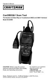
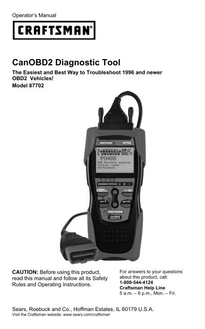
Operator’s Manual<br />
<strong>CanOBD2</strong> <strong>Diagnostic</strong> <strong>Tool</strong><br />
The Easiest and Best Way to Troubleshoot 1996 and newer<br />
OBD2 Vehicles!<br />
Model 87702<br />
CAUTION: Before using this product,<br />
read this manual and follow all its Safety<br />
Rules and Operating Instructions.<br />
For answers to your questions<br />
about this product, call:<br />
1-800-544-4124<br />
Craftsman Help Line<br />
5 a.m. – 6 p.m., Mon. – Fri.<br />
<strong>Sears</strong>, Roebuck and Co., Hoffman Estates, IL 60179 U.S.A.<br />
Visit the Craftsman website: www.sears.com/craftsman
Table of Contents<br />
INTRODUCTION<br />
WHAT IS OBD? ........................................................................ 1<br />
YOU CAN DO IT! .............................................................................. 2<br />
SAFETY PRECAUTIONS<br />
SAFETY FIRST! ........................................................................ 3<br />
ABOUT THE DIAGNOSTIC TOOL<br />
VEHICLES COVERED ............................................................. 5<br />
BATTERY REPLACEMENT ..................................................... 6<br />
ADJUSTMENTS/SETTINGS AND DTC LIBRARY .................. 6<br />
DIAGNOSTIC TOOL CONTROLS<br />
CONTROLS AND INDICATORS ............................................. 11<br />
DISPLAY FUNCTIONS ............................................................ 13<br />
ONBOARD DIAGNOSTICS<br />
COMPUTER ENGINE CONTROLS ......................................... 15<br />
DIAGNOSTIC TROUBLE CODES (DTCs) .............................. 20<br />
OBD2 MONITORS .................................................................... 23<br />
PREPARATION FOR TESTING<br />
PRELIMINARY VEHICLE DIAGNOSTIC WORKSHEET ......... 32<br />
BEFORE YOU BEGIN .............................................................. 35<br />
VEHICLE SERVICE MANUALS ............................................... 36<br />
USING THE DIAGNOSTIC TOOL<br />
CODE RETRIEVAL PROCEDURE .......................................... 37<br />
ERASING DIAGNOSTIC TROUBLE CODES (DTCs).............. 43<br />
I/M READINESS TESTING ...................................................... 44<br />
GLOSSARY<br />
INTRODUCTION....................................................................... 50<br />
GLOSSARY OF TERMS AND ABBREVIATIONS ................... 50<br />
WARRANTY AND SERVICING<br />
LIMITED ONE YEAR WARRANTY .......................................... 53<br />
SERVICE PROCEDURES ....................................................... 53<br />
i OBD2
WHAT IS OBD?<br />
Introduction<br />
WHAT IS OBD?<br />
The <strong>CanOBD2</strong> <strong>Diagnostic</strong> <strong>Tool</strong> is designed to work on all OBD2<br />
compliant vehicles. All 1996 and newer vehicles (cars, light trucks<br />
and SUVs) sold in the United States are OBD2 compliant.<br />
One of the most exciting improvements in the<br />
automobile industry was the addition of onboard<br />
diagnostics (OBD) on vehicles, or in more<br />
basic terms, the computer that activates the<br />
vehicle’s “CHECK ENGINE” light. OBD1 was<br />
designed to monitor manufacturer-specific<br />
systems on vehicles built from 1981 to 1995.<br />
Then came the development of OBD2, which is<br />
on all 1996 and newer vehicles sold in the U.S. Like its predecessor,<br />
OBD2 was adopted as part of a government mandate to lower vehicle<br />
emissions. But what makes OBD2 unique is its universal application for<br />
all late model cars and trucks - domestic and import. This sophisticated<br />
program in the vehicle’s main computer system is designed to detect<br />
failures in a range of systems, and can be accessed through a universal<br />
OBD2 port, which is usually found under the dashboard. For all OBD<br />
systems, if a problem is found, the computer turns on the “CHECK<br />
ENGINE” light to warn the driver, and sets a <strong>Diagnostic</strong> Trouble Code<br />
(DTC) to identify where the problem occurred. A special diagnostic tool,<br />
such as the <strong>CanOBD2</strong> <strong>Diagnostic</strong> <strong>Tool</strong>, is required to retrieve these<br />
codes, which consumers and professionals use as a starting point for<br />
repairs.<br />
To learn more about vehicle Computer Control Systems and<br />
OBD2, see COMPUTER ENGINE CONTROLS on page 14.<br />
OBD2 1
You Can Do It!<br />
EASY TO USE - EASY TO VIEW - EASY TO DEFINE<br />
Easy To Use . . . .<br />
� Connect the <strong>Diagnostic</strong> <strong>Tool</strong> to the<br />
vehicle’s test connector.<br />
� Turn the ignition key "On.”<br />
� Press the LINK button.<br />
Easy To View . . . .<br />
� The <strong>Diagnostic</strong> <strong>Tool</strong> retrieves stored<br />
codes, Freeze Frame data and I/M<br />
Readiness status.<br />
� Codes, I/M Readiness status and<br />
Freeze Frame data are displayed on the<br />
<strong>Diagnostic</strong> <strong>Tool</strong>’s LCD display screen.<br />
System status is indicated by LED<br />
indicators.<br />
Easy To Define . . . .<br />
� Read code definitions from the<br />
�<br />
<strong>Diagnostic</strong> <strong>Tool</strong>’s LCD display.<br />
View Freeze Frame data.<br />
2 OBD2
SAFETY FIRST!<br />
Safety Precautions<br />
SAFETY FIRST!<br />
This manual describes common test procedures used<br />
by experienced service technicians. Many test procedures<br />
require precautions to avoid accidents that can result in<br />
personal injury, and/or damage to your vehicle or test<br />
equipment. Always read your vehicle's service manual and<br />
follow its safety precautions before and during any test or<br />
service procedure. ALWAYS observe the following general<br />
safety precautions:<br />
P<br />
To avoid personal injury, instrument damage and/or<br />
damage to your vehicle; do not use the OBD2 Code Reader<br />
before reading this manual.<br />
R<br />
When an engine is running, it produces carbon monoxide,<br />
a toxic and poisonous gas. To prevent serious injury or<br />
death from carbon monoxide poisoning, operate the<br />
vehicle ONLY in a well-ventilated area.<br />
To protect your eyes from propelled objects as well as hot<br />
or caustic liquids, always wear approved safety eye<br />
protection.<br />
When an engine is running, many parts (such as the<br />
coolant fan, pulleys, fan belt etc.) turn at high speed. To<br />
avoid serious injury, always be aware of moving parts.<br />
Keep a safe distance from these parts as well as other<br />
potentially moving objects.<br />
Engine parts become very hot when the engine is running.<br />
To prevent severe burns, avoid contact with hot engine<br />
parts.<br />
Before starting an engine for testing or troubleshooting,<br />
make sure the parking brake is engaged. Put the<br />
N L<br />
transmission in park (for automatic transmission) or<br />
neutral (for manual transmission). Block the drive wheels<br />
with suitable blocks.<br />
Connecting or disconnecting test equipment when the<br />
ignition is ON can damage test equipment and the<br />
vehicle's electronic components. Turn the ignition OFF<br />
before connecting the <strong>Diagnostic</strong> <strong>Tool</strong> to or disconnecting<br />
the <strong>Diagnostic</strong> <strong>Tool</strong> from the vehicle’s Data Link Connector<br />
(DLC).<br />
D<br />
OBD2 3
Safety Precautions<br />
SAFETY FIRST!<br />
To prevent damage to the on-board computer when taking<br />
vehicle electrical measurements, always use a digital<br />
multimeter with at least 10 megOhms of impedance.<br />
Fuel and battery vapors are highly flammable. To prevent<br />
an explosion, keep all sparks, heated items and open<br />
flames away from the battery and fuel / fuel vapors. DO<br />
NOT SMOKE NEAR THE VEHICLE DURING TESTING.<br />
Don't wear loose clothing or jewelry when working on an<br />
engine. Loose clothing can become caught in the fan,<br />
pulleys, belts, etc. Jewelry is highly conductive, and can<br />
cause a severe burn if it makes contact between a power<br />
source and ground.<br />
4 OBD2
VEHICLES COVERED<br />
VEHICLE EMISSION CONTROL INFORMATION<br />
VEHICLE<br />
MANUFACTURER<br />
ENGINE FAMILY EFN2.6YBT2BA<br />
DISPLACEMENT 2.6L<br />
About the <strong>Diagnostic</strong> <strong>Tool</strong><br />
VEHICLES COVERED<br />
The <strong>CanOBD2</strong> <strong>Diagnostic</strong> <strong>Tool</strong> is designed to work on all OBD2<br />
compliant vehicles. All 1996 and newer vehicles (cars and light trucks)<br />
sold in the United States are OBD2 compliant.<br />
Federal law requires that all 1996 and newer cars and light<br />
trucks sold in the United States must be OBD2 compliant; this<br />
includes all Domestic, Asian and European vehicles.<br />
Some 1994 and 1995 vehicles are OBD2 compliant. To find out if a<br />
1994 or 1995 vehicle is OBD2 compliant, check the following:<br />
1. The Vehicle Emissions Control Information (VECI) Label. This<br />
label is located under the hood or by the radiator of most vehicles. If<br />
the vehicle is OBD2 compliant, the label will state “OBD II<br />
Certified.”<br />
OBD II<br />
CERTIFIED<br />
THIS VEHICLE CONFORMS TO U.S. EPA AND STATE<br />
OF CALIFORNIA REGULATIONS APPLICABLE TO<br />
1999 MODEL YEAR NEW TLEV PASSENGER CARS.<br />
REFER TO SERVICE MANUAL FOR ADDITIONAL INFORMATION<br />
TUNE-UP CONDITIONS: NORMAL OPERATING ENGINE TEMPERATURE,<br />
ACCESSORIES OFF, COOLING FAN OFF, TRANSMISSION IN NEUTRAL<br />
EXHAUST EMISSIONS STANDARDS STANDARD CATEGORY<br />
CERTIFICATION<br />
IN-USE<br />
SPARK PLUG<br />
TYPE NGK BPRE-11<br />
GAP: 1.1MM<br />
CATALYST<br />
TLEV<br />
TLEV INTERMEDIATE<br />
2. Government Regulations require that all<br />
OBD2 compliant vehicles must have a<br />
“common” sixteen-pin Data Link<br />
Connector (DLC).<br />
OBD II<br />
CERTIFIED<br />
Some 1994 and 1995 vehicles have 16-pin connectors but are<br />
not OBD2 compliant. Only those vehicles with a Vehicle<br />
Emissions Control Label stating “OBD II Certified” are OBD2<br />
compliant.<br />
Data Link Connector (DLC) Location<br />
The 16-pin DLC is usually<br />
located under the instrument<br />
panel (dash), within 12 inches<br />
(300 mm) of center of the panel,<br />
on the driver’s side of most<br />
vehicles. It should be easily<br />
accessible and visible from a<br />
kneeling position outside the<br />
vehicle with the door open.<br />
LEFT CORNER<br />
OF DASH<br />
NEAR<br />
CENTER<br />
OF DASH<br />
1 2 3 4 5 6 7 8<br />
9 10111213141516<br />
BEHIND<br />
ASHTRAY<br />
OBD2 5
About the <strong>Diagnostic</strong> <strong>Tool</strong><br />
BATTERY REPLACEMENT / ADJUSTMENTS/SETTINGS AND DTC LIBRARY<br />
On some Asian and European vehicles the DLC is located<br />
behind the “ashtray” (the ashtray must be removed to access it)<br />
or on the far left corner of the dash. If the DLC cannot be<br />
located, consult the vehicle’s service manual for the location.<br />
BATTERY REPLACEMENT<br />
Replace batteries when the battery symbol is visible on display<br />
and/or the 3 LEDS are all lit and no other data is visible on screen.<br />
1. Locate the battery cover on the back of the <strong>Diagnostic</strong> <strong>Tool</strong>.<br />
2. Slide the battery cover off (use your fingers).<br />
3. Replace batteries with two AA-size batteries (for longer life, use<br />
Alkaline-type batteries).<br />
4. Reinstall the battery cover on the back of the <strong>Diagnostic</strong> <strong>Tool</strong>.<br />
Language Selection After Battery Installation<br />
The first time the unit is turned on, you must select the desired display<br />
language (English, French or Spanish) as follows:<br />
1. Press the POWER/LINK button to<br />
turn the <strong>Diagnostic</strong> <strong>Tool</strong> “ON.”<br />
� The Select Language screen<br />
displays.<br />
2. Use the UP and DOWN<br />
buttons, as necessary, to highlight the<br />
desired display language.<br />
3. When the desired display language is selected, press the<br />
ENTER/FF button to confirm your selection.<br />
After the initial language selection is performed, it, as well as<br />
other settings, can be changed as desired. Proceed to<br />
“ADJUSTMENTS/SETTINGS AND DTC LIBRARY” below for<br />
further instructions.<br />
ADJUSTMENTS/SETTINGS AND DTC LIBRARY<br />
The <strong>Diagnostic</strong> <strong>Tool</strong> lets you make several adjustments and settings to<br />
configure the <strong>Diagnostic</strong> <strong>Tool</strong> to your particular needs. It also contains<br />
an OBD2 DTC Library that allows you to search for DTC definitions. The<br />
following functions, adjustments and settings can be performed when<br />
the <strong>Diagnostic</strong> <strong>Tool</strong> is in “MENU Mode”:<br />
� Adjust Brightness: Adjusts the brightness of the LCD display<br />
screen.<br />
� DTC Library: Lets you search the library of OBD2 DTC definitions.<br />
6 OBD2
About the <strong>Diagnostic</strong> <strong>Tool</strong><br />
ADJUSTMENTS / SETTINGS AND DTC LIBRARY<br />
� Select Language: Sets the display language for the <strong>Diagnostic</strong> <strong>Tool</strong><br />
to English, French or Spanish.<br />
� Unit of Measurement: Sets the Unit of Measurement for the<br />
<strong>Diagnostic</strong> <strong>Tool</strong>’s display to USA or metric.<br />
Adjustments and settings can be made only when the<br />
<strong>Diagnostic</strong> <strong>Tool</strong> is NOT connected to a vehicle.<br />
To enter the MENU Mode:<br />
1. With the <strong>Diagnostic</strong> <strong>Tool</strong> OFF, press<br />
and hold the UP button, then press<br />
and release the POWER/LINK<br />
button.<br />
� The adjustments and setting MENU<br />
displays.<br />
2. Release the UP button.<br />
DO NOT release the UP button until the adjustments and<br />
settings MENU is visible on the display.<br />
3. Make adjustments and settings as described in the following<br />
paragraphs.<br />
Adjusting Display Brightness<br />
1. Use the UP and DOWN buttons,<br />
as necessary, to highlight Adjust<br />
Brightness in the MENU, then press<br />
the ENTER/FF button.<br />
� The Adjust Brightness screen displays.<br />
� The Brightness field shows the current brightness setting, from<br />
1 to 8.<br />
2. Press the UP button to decrease the<br />
brightness of the LCD display (make the<br />
display darker).<br />
3. Press the DOWN button to increase<br />
the brightness of the LCD display (make<br />
the display lighter).<br />
4. When the desired brightness is obtained, press the ENTER/FF<br />
button to save your changes and return to the MENU.<br />
OBD2 7
About the <strong>Diagnostic</strong> <strong>Tool</strong><br />
ADJUSTMENTS / SETTINGS AND DTC LIBRARY<br />
Searching for a DTC Definition Using the DTC Library<br />
1. Use the UP and DOWN buttons,<br />
as necessary, to highlight DTC Library<br />
in the MENU, then press the ENTER/FF<br />
button.<br />
� The Enter DTC screen displays. The<br />
screen shows the code “P0001”,<br />
with the “P” flashing.<br />
2. Use the UP and DOWN buttons,<br />
as necessary, to scroll to the desired<br />
DTC type (P=Powertrain, U=Network,<br />
B=Body, C=Chassis), then press the<br />
DTC SCROLL button.<br />
� The selected character displays “solid”,<br />
and the next character begins flashing.<br />
3. Select the remaining characters in the DTC in the same way,<br />
pressing the DTC SCROLL button to confirm each character.<br />
When you have selected all the DTC characters, press the<br />
ENTER/FF button to view the DTC definition.<br />
� If you entered a “Generic” DTC<br />
(DTCs that start with “P0”, “P2” and<br />
some “P3”):<br />
- The selected DTC and DTC<br />
definition (if available), show on<br />
the <strong>Diagnostic</strong> <strong>Tool</strong>’s LCD display.<br />
� If you entered a “Manufacturer-<br />
Specific” DTC (DTCs that start with<br />
“P1” and some “P3”):<br />
- The “Select Manufacturer” screen<br />
displays.<br />
- Use the UP and DOWN<br />
buttons, as necessary, to highlight<br />
the appropriate manufacturer, then press the ENTER/FF<br />
button to display the correct DTC for your vehicle. A<br />
confirmation message shows on the LCD display.<br />
- If the correct manufacturer is<br />
shown, press the ENTER/FF<br />
button to continue.<br />
- If the correct manufacturer is not<br />
shown, press the DTC SCROLL<br />
button to return to the list of<br />
vehicle manufacturers.<br />
8 OBD2
About the <strong>Diagnostic</strong> <strong>Tool</strong><br />
ADJUSTMENTS / SETTINGS AND DTC LIBRARY<br />
If a definition for the DTC you<br />
entered is not available, an<br />
advisory message shows on the<br />
<strong>CanOBD2</strong> <strong>Diagnostic</strong> <strong>Tool</strong>’s<br />
display.<br />
4. If you wish to view definitions for additional DTCs, press the<br />
ENTER/FF button to return to the DTC Library screen, and<br />
repeat steps 2 and 3.<br />
5. When all desired DTCs have been viewed, press the ERASE<br />
button to exit the DTC Library.<br />
Selecting the Display Language<br />
1. Use the UP and DOWN buttons,<br />
as necessary, to highlight Select<br />
Language in the MENU, then press the<br />
ENTER/FF button.<br />
� The Select Language screen displays.<br />
� The currently selected display Language is highlighted.<br />
2. Press the UP or DOWN button,<br />
as necessary, to highlight the desired<br />
display language.<br />
3. When the desired display language is highlighted,<br />
press the ENTER/FF button to<br />
save your changes and return to the MENU<br />
(shown in the selected display language).<br />
Setting the Unit of Measurement<br />
1. Use the UP and DOWN buttons,<br />
as necessary, to highlight Unit of<br />
Measurement in the MENU, then press<br />
the ENTER/FF button.<br />
2. Press the UP or DOWN button,<br />
as necessary, to highlight the desired<br />
Unit of Measurement.<br />
3. When the desired Unit of<br />
Measurement value is selected, press<br />
the ENTER/FF button to save your<br />
changes.<br />
OBD2 9
About the <strong>Diagnostic</strong> <strong>Tool</strong><br />
ADJUSTMENTS / SETTINGS AND DTC LIBRARY<br />
Exiting the MENU Mode<br />
1. Use the UP and DOWN buttons, as necessary, to highlight<br />
Menu Exit in the MENU, then press the ENTER/FF button.<br />
� The LCD display returns to the DTC screen (if data is currently<br />
stored in the <strong>Diagnostic</strong> <strong>Tool</strong>’s memory) or the “To Link” screen<br />
(if no data is stored).<br />
10 OBD2
CONTROLS AND INDICATORS<br />
7<br />
6<br />
1<br />
2<br />
5<br />
<strong>Diagnostic</strong> <strong>Tool</strong> Controls<br />
CONTROLS AND INDICATORS<br />
11<br />
10<br />
9<br />
3<br />
Figure 1. Controls and Indicators<br />
See Figure 1 for the locations of items 1 through 11, below.<br />
1. ERASE button - Erases <strong>Diagnostic</strong> Trouble Codes (DTCs), and<br />
“Freeze Frame” data from your vehicle’s computer, and resets<br />
Monitor status.<br />
2. DTC SCROLL button - Displays the DTC View screen and/or<br />
scrolls the LCD display to view DTCs when more than one DTC is<br />
present.<br />
3. POWER/LINK button - When the <strong>Diagnostic</strong> <strong>Tool</strong> IS NOT<br />
connected to a vehicle, turns the <strong>Diagnostic</strong> <strong>Tool</strong> “On” and “Off”.<br />
When the <strong>Diagnostic</strong> <strong>Tool</strong> is connected to a vehicle, links the<br />
<strong>Diagnostic</strong> <strong>Tool</strong> to the vehicle’s PCM to retrieve diagnostic data from<br />
the computer’s memory.<br />
To turn the <strong>Diagnostic</strong> <strong>Tool</strong> "On", you must press and hold the<br />
POWER/LINK button for approximately 3 seconds.<br />
4. ENTER/FREEZE FRAME button - When in MENU mode,<br />
confirms the selected option or value. When retrieving and viewing<br />
DTCs, displays Freeze Frame data for the highest priority code.<br />
OBD2 11<br />
8<br />
4
<strong>Diagnostic</strong> <strong>Tool</strong> Controls<br />
CONTROLS AND INDICATORS<br />
5. DOWN button - When in MENU mode, scrolls DOWN through<br />
the menu and submenu selection options. When retrieving and<br />
viewing DTCs, scrolls down through the current display screen to<br />
display any additional data.<br />
6. UP button - When in MENU mode, scrolls UP through the menu<br />
and submenu selection options. When retrieving and viewing DTCs,<br />
scrolls ups through the current display screen to display any<br />
additional data.<br />
7. GREEN LED - Indicates that all engine systems are running<br />
normally (all Monitors on the vehicle are active and performing their<br />
diagnostic testing, and no DTCs are present).<br />
8. YELLOW LED - Indicates there is a possible problem. A “Pending”<br />
DTC is present and/or some of the vehicle’s emission monitors have<br />
not run their diagnostic testing.<br />
9. RED LED - Indicates there is a problem in one or more of the<br />
vehicle’s systems. The red LED is also used to show that DTC(s)<br />
are present. DTCs are shown on the <strong>Diagnostic</strong> <strong>Tool</strong>’s LCD display.<br />
In this case, the Multifunction Indicator (“Check Engine”) lamp on<br />
the vehicle’s instrument panel will light steady on.<br />
10. LCD Display - Displays settings Menu and submenus, test results,<br />
<strong>Diagnostic</strong> <strong>Tool</strong> functions and Monitor status information. See<br />
DISPLAY FUNCTIONS, on next page, for more details.<br />
11. CABLE - Connects the <strong>Diagnostic</strong> <strong>Tool</strong> to the vehicle’s Data Link<br />
Connector (DLC).<br />
12 OBD2
DISPLAY FUNCTIONS<br />
3<br />
4<br />
5<br />
6<br />
7<br />
2 1 11 12 13<br />
<strong>Diagnostic</strong> <strong>Tool</strong> Controls<br />
DISPLAY FUNCTIONS<br />
8 9<br />
Figure 2. Display Functions<br />
See Figure 2 for the locations of items 1 through 16, below.<br />
1. I/M MONITOR STATUS field - Identifies the I/M Monitor status area.<br />
2. Monitor icons - Indicate which Monitors are supported by the<br />
vehicle under test, and whether or not the associated Monitor has<br />
run its diagnostic testing (Monitor status). When a Monitor icon is<br />
solid, it indicates that the associated Monitor has completed its<br />
diagnostic testing. When a Monitor icon is flashing, it indicates that<br />
the vehicle supports the associated Monitor, but the Monitor has not<br />
yet run its diagnostic testing.<br />
3. Vehicle icon - Indicates whether or not the <strong>Diagnostic</strong> <strong>Tool</strong> is<br />
being properly powered through the vehicle’s Data Link Connector<br />
(DLC). A visible icon indicates that the <strong>Diagnostic</strong> <strong>Tool</strong> is being<br />
powered through the vehicle’s DLC connector.<br />
4. Link icon - Indicates whether or not the <strong>Diagnostic</strong> <strong>Tool</strong> is<br />
communicating (linked) with the vehicle’s on-board computer. When<br />
visible, the <strong>Diagnostic</strong> <strong>Tool</strong> is communicating with the computer. If<br />
the Link icon is not visible, the <strong>Diagnostic</strong> <strong>Tool</strong> is not communicating<br />
with the computer.<br />
5. Computer icon - When this icon is visible it indicates that the<br />
<strong>Diagnostic</strong> <strong>Tool</strong> is linked to a personal computer. An optional “PC<br />
Link Kit” is available that makes it possible to upload retrieved data<br />
to a personal computer.<br />
6. <strong>Diagnostic</strong> <strong>Tool</strong> Internal Battery icon - When visible, indicates<br />
the <strong>Diagnostic</strong> <strong>Tool</strong> batteries are “low” and should be replaced. If the<br />
batteries are not replaced when the battery symbol is "on", all 3<br />
LEDs will light up as a last resort indicator to warn you that the<br />
batteries need replacement. No data will be displayed on screen<br />
when all 3 LEDs are lit.<br />
OBD2 13<br />
14<br />
10
<strong>Diagnostic</strong> <strong>Tool</strong> Controls<br />
DISPLAY FUNCTIONS<br />
7. DTC Display Area - Displays the <strong>Diagnostic</strong> Trouble Code (DTC)<br />
number. Each fault is assigned a code number that is specific to that<br />
fault.<br />
8. Test Data Display Area - Displays DTC definitions, Freeze Frame<br />
data, and other pertinent test information messages.<br />
9. FREEZE FRAME icon - Indicates that there is Freeze Frame data<br />
from “Priority Code” (Code #1) stored in the vehicle’s computer<br />
memory.<br />
10. PERMANENT icon - Indicates the currently displayed DTC is a<br />
“Permanent” code.<br />
11. PENDING icon - Indicates the currently displayed DTC is a<br />
“Pending” code.<br />
12. MIL icon - Indicates the status of the Malfunction Indicator Lamp<br />
(MIL). The MIL icon is visible only when a DTC has commanded the<br />
MIL on the vehicle’s dashboard to light.<br />
13. Code Number Sequence - The <strong>Diagnostic</strong> <strong>Tool</strong> assigns a<br />
sequence number to each DTC that is present in the computer’s<br />
memory, starting with “01.” This number indicates which code is<br />
currently displayed. Code number “01” is always the highest priority<br />
code, and the one for which “Freeze Frame” data has been stored.<br />
If “01” is a “Pending” code, there may or may not be<br />
“Freeze Frame” data stored in memory.<br />
14. Code Enumerator - Indicates the total number of codes retrieved<br />
from the vehicle’s computer.<br />
14 OBD2
COMPUTER ENGINE CONTROLS<br />
The Introduction of Electronic Engine Controls<br />
Onboard <strong>Diagnostic</strong>s<br />
COMPUTER ENGINE CONTROLS<br />
Electronic Computer Control Systems make it possible<br />
for vehicle manufacturers to comply with the tougher<br />
emissions and fuel efficiency standards mandated by<br />
State and Federal Governments.<br />
As a result of increased air pollution (smog) in large cities,<br />
such as Los Angeles, the California Air Resources Board<br />
(CARB) and the Environmental Protection Agency (EPA)<br />
set new regulations and air pollution standards to deal with<br />
the problem. To further complicate matters, the energy crisis of<br />
the early 1970s caused a sharp increase in fuel prices over a<br />
short period. As a result, vehicle manufacturers were not only<br />
required to comply with the new emissions standards, they also<br />
had to make their vehicles more fuel-efficient. Most vehicles<br />
were required to meet a miles-per-gallon (MPG) standard set by the U.S.<br />
Federal Government.<br />
Precise fuel delivery and spark timing are needed to reduce vehicle<br />
emissions. Mechanical engine controls in use at the time (such as<br />
ignition points, mechanical spark advance and the carburetor)<br />
responded too slowly to driving conditions to properly control fuel<br />
delivery and spark timing. This made it difficult for vehicle manufacturers<br />
to meet the new standards.<br />
A new Engine Control System had to be designed and integrated with<br />
the engine controls to meet the stricter standards. The new system had<br />
to:<br />
� Respond instantly to supply the proper mixture of air and fuel for any<br />
driving condition (idle, cruising, low-speed driving, high-speed<br />
driving, etc.).<br />
� Calculate instantly the best time to “ignite” the air/fuel mixture for<br />
maximum engine efficiency.<br />
� Perform both these tasks without affecting vehicle performance or<br />
fuel economy.<br />
Vehicle Computer Control Systems can perform millions of calculations<br />
each second. This makes them an ideal substitute for the slower<br />
mechanical engine controls. By switching from mechanical to electronic<br />
engine controls, vehicle manufacturers are able to control fuel delivery<br />
and spark timing more precisely. Some newer Computer Control<br />
Systems also provide control over other vehicle functions, such as<br />
transmission, brakes, charging, body, and suspension systems.<br />
OBD2 15
Onboard <strong>Diagnostic</strong>s<br />
COMPUTER ENGINE CONTROLS<br />
The Basic Engine Computer Control System<br />
The Computer Control System consists of an on-board<br />
computer and several related control devices (sensors,<br />
switches, and actuators).<br />
The on-board computer is the heart of the Computer<br />
Control System. The computer contains several programs<br />
with preset reference values for air/fuel ratio, spark or<br />
ignition timing, injector pulse width, engine speed, etc.<br />
Separate values are provided for various driving conditions,<br />
such as idle, low speed driving, high-speed driving, low load,<br />
or high load. The preset reference values represent the ideal<br />
air/fuel mixture, spark timing, transmission gear selection,<br />
etc., for any driving condition. These values are programmed<br />
by the vehicle manufacturer, and are specific to each vehicle model.<br />
Most on-board computers are located inside the vehicle behind the dashboard,<br />
under the passenger’s or driver’s seat, or behind the right kick panel. However,<br />
some manufacturers may still position it in the engine compartment.<br />
Vehicle sensors, switches, and actuators are located throughout the<br />
engine, and are connected by electrical wiring to the on-board computer.<br />
These devices include oxygen sensors, coolant temperature sensors,<br />
throttle position sensors, fuel injectors, etc. Sensors and switches are<br />
input devices. They provide signals representing current engine<br />
operating conditions to the computer. Actuators are output devices. They<br />
perform actions in response to commands received from the computer.<br />
The on-board computer receives information inputs from sensors and<br />
switches located throughout the engine. These devices monitor critical<br />
engine conditions such as coolant temperature, engine speed, engine<br />
load, throttle position, air/fuel ratio etc.<br />
The computer compares the values received from these sensors with its<br />
preset reference values, and makes corrective actions as needed so<br />
that the sensor values always match the preset reference values for the<br />
current driving condition. The computer makes adjustments by<br />
commanding other devices such as the fuel injectors, idle air control,<br />
EGR valve or Ignition Module to perform these actions.<br />
OUTPUT DEVICES<br />
Fuel Injectors<br />
Idle Air Control<br />
EGR Valve<br />
Ignition Module<br />
INPUT DEVICES<br />
Coolant Temperature Sensor<br />
Throttle Position Sensor<br />
Fuel Injectors<br />
On-Board<br />
Computer<br />
TYPICAL COMPUTER<br />
CONTROL SYSTEM<br />
INPUT DEVICES<br />
Oxygen Sensors<br />
16 OBD2
Onboard <strong>Diagnostic</strong>s<br />
COMPUTER ENGINE CONTROLS<br />
Vehicle operating conditions are constantly changing. The computer<br />
continuously makes adjustments or corrections (especially to the air/fuel<br />
mixture and spark timing) to keep all the engine systems operating<br />
within the preset reference values.<br />
On-Board <strong>Diagnostic</strong>s - First Generation (OBD1)<br />
With the exception of some 1994 and 1995 vehicles,<br />
most vehicles from 1982 to 1995 are equipped with<br />
some type of first generation On-Board <strong>Diagnostic</strong>s.<br />
Beginning in 1988, California’s Air Resources Board<br />
(CARB), and later the Environmental Protection Agency (EPA)<br />
required vehicle manufacturers to include a self-diagnostic<br />
program in their on-board computers. The program would be<br />
capable of identifying emissions-related faults in a system. The<br />
first generation of Onboard <strong>Diagnostic</strong>s came to be known as<br />
OBD1.<br />
OBD1 is a set of self-testing and diagnostic instructions<br />
programmed into the vehicle’s on-board computer. The<br />
programs are specifically designed to detect failures in the sensors,<br />
actuators, switches and wiring of the various vehicle emissions-related<br />
systems. If the computer detects a failure in any of these components or<br />
systems, it lights an indicator on the dashboard to alert the driver. The<br />
indicator lights only when an emissions-related problem is detected.<br />
The computer also assigns a numeric code for each specific problem<br />
that it detects, and stores these codes in its memory for later retrieval.<br />
These codes can be retrieved from the computer’s memory with the use<br />
of a “Code Reader” or a “Scan <strong>Tool</strong>.”<br />
On-Board <strong>Diagnostic</strong>s - Second Generation (OBD2)<br />
In addition to performing all the<br />
functions of the OBD1 System, the<br />
OBD2 System has been enhanced with<br />
new <strong>Diagnostic</strong> Programs. These<br />
programs closely monitor the functions<br />
of various emissions-related components<br />
and systems (as well as other<br />
The OBD2 System is<br />
an enhancement of the<br />
OBD1 System.<br />
systems) and make this information readily available (with<br />
the proper equipment) to the technician for evaluation.<br />
The California Air Resources Board (CARB) conducted<br />
studies on OBD1 equipped vehicles. The information that was<br />
gathered from these studies showed the following:<br />
� A large number of vehicles had deteriorating or degraded<br />
emissions-related components. These components were<br />
causing an increase in emissions.<br />
OBD2 17
Onboard <strong>Diagnostic</strong>s<br />
COMPUTER ENGINE CONTROLS<br />
� Because OBD1 systems only detect failed components, the<br />
degraded components were not setting codes.<br />
� Some emissions problems related to degraded components only<br />
occur when the vehicle is being driven under a load. The emission<br />
checks being conducted at the time were not performed under<br />
simulated driving conditions. As a result, a significant number of<br />
vehicles with degraded components were passing Emissions Tests.<br />
� Codes, code definitions, diagnostic connectors, communication<br />
protocols and emissions terminology were different for each<br />
manufacturer. This caused confusion for the technicians working on<br />
different make and model vehicles.<br />
To address the problems made evident by this study, CARB and the<br />
EPA passed new laws and standardization requirements. These laws<br />
required that vehicle manufacturers to equip their new vehicles with<br />
devices capable of meeting all of the new emissions standards and<br />
regulations. It was also decided that an enhanced on-board diagnostic<br />
system, capable of addressing all of these problems, was needed. This<br />
new system is known as “On-Board <strong>Diagnostic</strong>s Generation Two<br />
(OBD2).” The primary objective of the OBD2 system is to comply with<br />
the latest regulations and emissions standards established by CARB<br />
and the EPA.<br />
The Main Objectives of the OBD2 System are:<br />
� To detect degraded and/or failed emissions-related components or<br />
systems that could cause tailpipe emissions to exceed by 1.5 times<br />
the Federal Test Procedure (FTP) standard.<br />
� To expand emissions-related system monitoring. This includes a set<br />
of computer run diagnostics called Monitors. Monitors perform<br />
diagnostics and testing to verify that all emissions-related<br />
components and/or systems are operating correctly and within the<br />
manufacturer’s specifications.<br />
� To use a standardized <strong>Diagnostic</strong> Link Connector (DLC) in all<br />
vehicles. (Before OBD2, DLCs were of different shapes and sizes.)<br />
� To standardize the code numbers, code definitions and language<br />
used to describe faults. (Before OBD2, each vehicle manufacturer<br />
used their own code numbers, code definitions and language to<br />
describe the same faults.)<br />
� To expand the operation of the Malfunction Indicator Lamp (MIL).<br />
� To standardize communication procedures and protocols between<br />
the diagnostic equipment (Scan <strong>Tool</strong>s, Code Readers, etc.) and the<br />
vehicle’s on-board computer.<br />
OBD2 Terminology<br />
The following terms and their definitions are related to OBD2 systems.<br />
Read and reference this list as needed to aid in the understanding of<br />
OBD2 systems.<br />
18 OBD2
Onboard <strong>Diagnostic</strong>s<br />
COMPUTER ENGINE CONTROLS<br />
� Powertrain Control Module (PCM) - The PCM is the OBD2<br />
accepted term for the vehicle’s “on-board computer.” In addition<br />
to controlling the engine management and emissions systems,<br />
the PCM also participates in controlling the powertrain<br />
�<br />
(transmission) operation. Most PCMs also have the ability to<br />
communicate with other computers on the vehicle (ABS, ride<br />
control, body, etc.).<br />
Monitor - Monitors are “diagnostic routines” programmed into the<br />
PCM. The PCM utilizes these programs to run diagnostic tests, and<br />
to monitor operation of the vehicle’s emissions-related components<br />
or systems to ensure they are operating correctly and within the<br />
vehicle’s manufacturer specifications. Currently, up to eleven<br />
Monitors are used in OBD2 systems. Additional Monitors will be<br />
added as the OBD2 system is further developed.<br />
Not all vehicles support all eleven Monitors.<br />
� Enabling Criteria - Each Monitor is designed to test and monitor<br />
the operation of a specific part of the vehicle’s emissions system<br />
(EGR system, oxygen sensor, catalytic converter, etc.). A specific<br />
set of “conditions” or “driving procedures” must be met before the<br />
computer can command a Monitor to run tests on its related system.<br />
These “conditions” are known as “Enabling Criteria.” The<br />
requirements and procedures vary for each Monitor. Some Monitors<br />
only require the ignition key to be turned “On” for them to run and<br />
complete their diagnostic testing. Others may require a set of<br />
complex procedures, such as, starting the vehicle when cold,<br />
bringing it to operating temperature, and driving the vehicle under<br />
specific conditions before the Monitor can run and complete its<br />
diagnostic testing.<br />
� Monitor Has/Has Not Run - The terms “Monitor has run” or<br />
“Monitor has not run” are used throughout this manual. “Monitor<br />
has run,” means the PCM has commanded a particular Monitor to<br />
perform the required diagnostic testing on a system to ensure the<br />
system is operating correctly (within factory specifications). The term<br />
“Monitor has not run” means the PCM has not yet commanded a<br />
particular Monitor to perform diagnostic testing on its associated part<br />
of the emissions system.<br />
� Trip - A Trip for a particular Monitor requires that the vehicle is<br />
being driven in such a way that all the required “Enabling Criteria”<br />
for the Monitor to run and complete its diagnostic testing are met.<br />
The “Trip Drive Cycle” for a particular Monitor begins when the<br />
ignition key is turned “On.” It is successfully completed when all the<br />
“Enabling Criteria” for the Monitor to run and complete its diagnostic<br />
testing are met by the time the ignition key is turned “Off.” Since<br />
each of the eleven monitors is designed to run diagnostics and<br />
testing on a different part of the engine or emissions system, the<br />
“Trip Drive Cycle” needed for each individual Monitor to run and<br />
complete varies.<br />
OBD2 19
Onboard <strong>Diagnostic</strong>s<br />
DIAGNOSTIC TROUBLE CODES (DTCs)<br />
� OBD2 Drive Cycle - An OBD2 Drive Cycle is an extended set of<br />
driving procedures that takes into consideration the various types of<br />
driving conditions encountered in real life. These conditions may<br />
include starting the vehicle when it is cold, driving the vehicle at a<br />
steady speed (cruising), accelerating, etc. An OBD2 Drive Cycle<br />
begins when the ignition key is turned “On” (when cold) and ends<br />
when the vehicle has been driven in such a way as to have all the<br />
“Enabling Criteria” met for all its applicable Monitors. Only those<br />
trips that provide the Enabling Criteria for all Monitors applicable to<br />
the vehicle to run and complete their individual diagnostic tests<br />
qualify as an OBD2 Drive Cycle. OBD2 Drive Cycle requirements<br />
vary from one model of vehicle to another. Vehicle manufacturers<br />
set these procedures. Consult your vehicle’s service manual for<br />
OBD2 Drive Cycle procedures.<br />
Do not confuse a “Trip” Drive Cycle with an OBD2 Drive Cycle.<br />
A “Trip” Drive Cycle provides the “Enabling Criteria” for one<br />
specific Monitor to run and complete its diagnostic testing. An<br />
OBD2 Drive Cycle must meet the “Enabling Criteria” for all<br />
Monitors on a particular vehicle to run and complete their<br />
diagnostic testing.<br />
� Warm-up Cycle - Vehicle operation after an engine off period where<br />
engine temperature rises at least 40°F (22°C) from its temperature<br />
before starting, and reaches at least 160°F (70°C). The PCM uses<br />
warm-up cycles as a counter to automatically erase a specific code<br />
and related data from its memory. When no faults related to the<br />
original problem are detected within a specified number of warm-up<br />
cycles, the code is erased automatically.<br />
DIAGNOSTIC TROUBLE CODES (DTCs)<br />
<strong>Diagnostic</strong> Trouble Codes (DTCs) are<br />
meant to guide you to the proper<br />
service procedure in the vehicle’s<br />
service manual. DO NOT replace parts<br />
based only on DTCs without first<br />
consulting the vehicle’s service manual<br />
for proper testing procedures for that<br />
particular system, circuit or component.<br />
<strong>Diagnostic</strong> Trouble<br />
Codes (DTCs) are<br />
codes that identify a<br />
specific problem area.<br />
DTCs are alphanumeric codes that are used to identify a<br />
problem that is present in any of the systems that are<br />
monitored by the on-board computer (PCM). Each trouble<br />
code has an assigned message that identifies the circuit,<br />
component or system area where the problem was found.<br />
OBD2 diagnostic trouble codes are made up of five characters:<br />
� The 1st character is a letter. It identifies the “main system” where<br />
the fault occurred (Body, Chassis, Powertrain, or Network).<br />
� The 2nd character is a numeric digit. It identifies the “type” of code<br />
(Generic or Manufacturer-Specific).<br />
20 OBD2
Onboard <strong>Diagnostic</strong>s<br />
DIAGNOSTIC TROUBLE CODES (DTCs)<br />
Generic DTCs are codes that are used by all vehicle manufacturers.<br />
The standards for generic DTCs, as well as their<br />
definitions, are set by the Society of Automotive Engineers (SAE).<br />
Manufacturer-Specific DTCs are codes that are controlled by<br />
the vehicle manufacturers. The Federal Government does not<br />
require vehicle manufacturers to go beyond the standardized<br />
generic DTCs in order to comply with the new OBD2 emissions<br />
standards. However, manufacturers are free to expand beyond<br />
the standardized codes to make their systems easier to<br />
diagnose.<br />
� The 3rd character is a numeric digit. It identifies the specific<br />
system or sub-system where the problem is located.<br />
� The 4th and 5th characters are numeric digits. They identify the<br />
section of the system that is malfunctioning.<br />
B<br />
C<br />
P<br />
U<br />
0<br />
1<br />
2<br />
3<br />
- Body<br />
-<br />
-<br />
-<br />
-<br />
-<br />
-<br />
-<br />
Chassis<br />
Powertrain<br />
Network<br />
Generic<br />
Manufacturer Specific<br />
Generic<br />
Includes both Generic and Manufacturer<br />
Specific Codes<br />
Identifies the system where the<br />
problem is located:<br />
1<br />
2<br />
3<br />
4<br />
5<br />
6<br />
7<br />
8<br />
-<br />
-<br />
-<br />
-<br />
-<br />
-<br />
-<br />
-<br />
OBD2 DTC EXAMPLE<br />
P0201 - Injector Circuit Malfunction, Cylinder 1<br />
Fuel and Air Metering<br />
Fuel and Air Metering (injector circuit<br />
malfunction only)<br />
Ignition System or Misfire<br />
Auxiliary Emission Control System<br />
Vehicle Speed Control and Idle Control<br />
System<br />
Computer Output Circuits<br />
Transmission<br />
Transmission<br />
Identifies what section of the system<br />
is malfunctioning<br />
P 0 2 0 1<br />
OBD2 21
Onboard <strong>Diagnostic</strong>s<br />
DIAGNOSTIC TROUBLE CODES (DTCs)<br />
DTCs and MIL Status<br />
When the vehicle’s on-board computer detects<br />
a failure in an emissions-related component or<br />
system, the computer’s internal diagnostic<br />
program assigns a diagnostic trouble code<br />
(DTC) that points to the system (and subsystem)<br />
where the fault was found. The diagnostic<br />
program saves the code in the computer’s<br />
memory. It records a “Freeze Frame” of conditions<br />
present when the fault was found, and lights the Malfunction<br />
Indicator Lamp (MIL). Some faults require detection for two trips in a row<br />
before the MIL is turned on.<br />
The “Malfunction Indicator Lamp” (MIL) is the accepted term<br />
used to describe the lamp on the dashboard that lights to warn<br />
the driver that an emissions-related fault has been found.<br />
Some manufacturers may still call this lamp a “Check Engine”<br />
or “Service Engine Soon” light.<br />
There are two types of DTCs used for emissions-related faults: Type “A”<br />
and Type “B.” Type “A” codes are “One-Trip” codes; Type “B” DTCs are<br />
usually Two-Trip DTCs.<br />
When a Type “A” DTC is found on the First Trip, the following events<br />
take place:<br />
� The computer commands the MIL “On” when the failure is first found.<br />
� If the failure causes a severe misfire that may cause damage to the<br />
catalytic converter, the MIL “flashes” once per second. The MIL<br />
continues to flash as long as the condition exists. If the condition<br />
that caused the MIL to flash is no longer present, the MIL will light<br />
“steady” On.<br />
� A DTC is saved in the computer’s memory for later retrieval.<br />
� A “Freeze Frame” of the conditions present in the engine or emissions<br />
system when the MIL was ordered “On” is saved in the computer’s<br />
memory for later retrieval. This information shows fuel system status<br />
(closed loop or open loop), engine load, coolant temperature, fuel trim<br />
value, MAP vacuum, engine RPM and DTC priority.<br />
When a Type “B” DTC is found on the First Trip, the following events<br />
take place:<br />
� The computer sets a Pending DTC, but the MIL is not ordered “On.”<br />
“Freeze Frame” data may or may not be saved at this time<br />
depending on manufacturer. The Pending DTC is saved in the<br />
computer’s memory for later retrieval.<br />
� If the failure is found on the second consecutive trip, the MIL is<br />
ordered “On.” “Freeze Frame” data is saved in the computer’s<br />
memory.<br />
� If the failure is not found on the second Trip, the Pending DTC is<br />
erased from the computer’s memory.<br />
The MIL will stay lit for both Type “A” and Type “B” codes until one of<br />
the following conditions occurs:<br />
22 OBD2
Onboard <strong>Diagnostic</strong>s<br />
DIAGNOSTIC TROUBLE CODES (DTCs)<br />
� If the conditions that caused the MIL to light are no longer present<br />
for the next three trips in a row, the computer automatically turns the<br />
MIL “Off” if no other emissions-related faults are present. However,<br />
the DTCs remain in the computer’s memory as a history code for 40<br />
warm-up cycles (80 warm-up cycles for fuel and misfire faults). The<br />
DTCs are automatically erased if the fault that caused them to be<br />
set is not detected again during that period.<br />
� Misfire and fuel system faults require three trips with “similar<br />
conditions” before the MIL is turned “Off.” These are trips where the<br />
engine load, RPM and temperature are similar to the conditions<br />
present when the fault was first found.<br />
After the MIL has been turned off, DTCs and Freeze Frame<br />
data stay in the computer’s memory.<br />
� Erasing the DTCs from the computer’s memory can also turn off the<br />
MIL. See ERASING DIAGNOSTIC TROUBLE CODES (DTCs) on<br />
page 43, before erasing codes from the computer’s memory. If a<br />
<strong>Diagnostic</strong> <strong>Tool</strong> or Scan <strong>Tool</strong> is used to erase the codes, Freeze<br />
Frame data will also be erased.<br />
OBD2 MONITORS<br />
To ensure the correct operation of the various emissions-related<br />
components and systems, a diagnostic program was developed and<br />
installed in the vehicle’s on-board computer. The program has several<br />
procedures and diagnostic strategies. Each procedure or diagnostic<br />
strategy is made to monitor the operation of, and run diagnostic tests on,<br />
a specific emissions-related component or system. These tests ensure<br />
the system is running correctly and is within the manufacturer’s<br />
specifications. On OBD2 systems, these procedures and diagnostic<br />
strategies are called “Monitors.”<br />
Currently, fifteen Monitors are supported by OBD2 systems. Additional<br />
monitors may be added as a result of Government regulations as the<br />
OBD2 system grows and matures. Not all vehicles support all fifteen<br />
Monitors. Additionally, some Monitors are supported by “spark ignition”<br />
vehicles only, while others are supported by “compression ignition”<br />
vehicles only.<br />
Monitor operation is either “Continuous” or “Non-Continuous,”<br />
depending on the specific monitor.<br />
Continuous Monitors<br />
Three of these Monitors are designed to constantly monitor their<br />
associated components and/or systems for proper operation.<br />
Continuous Monitors run constantly when the engine is running. The<br />
Continuous Monitors are:<br />
Comprehensive Component Monitor (CCM)<br />
Misfire Monitor<br />
Fuel System Monitor<br />
OBD2 23
Onboard <strong>Diagnostic</strong>s<br />
OBD2 MONITORS<br />
Non-Continuous Monitors<br />
The other twelve Monitors are “non-continuous” Monitors. “Noncontinuous”<br />
Monitors perform and complete their testing once per trip.<br />
The “non-continuous” Monitors are:<br />
Oxygen Sensor Monitor<br />
Oxygen Sensor Heater Monitor<br />
Catalyst Monitor<br />
Heated Catalyst Monitor<br />
EGR System Monitor<br />
EVAP System Monitor<br />
Secondary Air System Monitor<br />
The following Monitors will be standard beginning in 2010. The<br />
majority of vehicles produced before this time will not support<br />
these Monitors<br />
NMHC Monitor<br />
NOx Adsorber Monitor<br />
Boost Pressure System Monitor<br />
Exhaust Gas Sensor Monitor<br />
PM Filter Monitor<br />
The following provides a brief explanation of the function of each Monitor:<br />
Comprehensive Component Monitor (CCM) - This Monitor<br />
continuously checks all inputs and outputs from sensors,<br />
actuators, switches and other devices that provide a signal to the<br />
computer. The Monitor checks for shorts, opens, out of range value,<br />
functionality and “rationality.”<br />
Rationality: Each input signal is compared against all other<br />
inputs and against information in the computer’s memory to see<br />
if it makes sense under the current operating conditions.<br />
Example: The signal from the throttle position sensor indicates<br />
the vehicle is in a wide-open throttle condition, but the vehicle is<br />
really at idle, and the idle condition is confirmed by the signals<br />
from all other sensors. Based on the input data, the computer<br />
determines that the signal from the throttle position sensor is not<br />
rational (does not make sense when compared to the other<br />
inputs). In this case, the signal would fail the rationality test.<br />
The CCM is supported by both “spark ignition” vehicles and<br />
“compression ignition” vehicles. The CCM may be either a “One-Trip” or<br />
a “Two-Trip” Monitor, depending on the component.<br />
24 OBD2
Onboard <strong>Diagnostic</strong>s<br />
OBD2 MONITORS<br />
Fuel System Monitor - This Monitor uses a Fuel System<br />
Correction program, called Fuel Trim, inside the on-board<br />
computer. Fuel Trim is a set of positive and negative values that<br />
represent adding or subtracting fuel from the engine. This program is<br />
used to correct for a lean (too much air/not enough fuel) or rich (too<br />
much fuel/not enough air) air-fuel mixture. The program is designed to<br />
add or subtract fuel, as needed, up to a certain percent. If the correction<br />
needed is too large and exceeds the time and percent allowed by the<br />
program, a fault is indicated by the computer.<br />
The Fuel System Monitor is supported by both “spark ignition” vehicles<br />
and “compression ignition” vehicles. The Fuel System Monitor may be a<br />
“One-Trip” or “Two-Trip” Monitor, depending on the severity of the<br />
problem.<br />
Misfire Monitor - This Monitor continuously checks for engine misfires.<br />
A misfire occurs when the air-fuel mixture in the cylinder does not ignite.<br />
The misfire Monitor uses changes in crankshaft speed to sense an engine<br />
misfire. When a cylinder misfires, it no longer contributes to the speed of the<br />
engine, and engine speed decreases each time the affected cylinder(s) misfire.<br />
The misfire Monitor is designed to sense engine speed fluctuations and<br />
determine from which cylinder(s) the misfire is coming, as well as how bad the<br />
misfire is. There are three types of engine misfires, Types 1, 2, and 3.<br />
- Type 1 and Type 3 misfires are two-trip monitor faults. If a fault is sensed<br />
on the first trip, the computer temporarily saves the fault in its memory as<br />
a Pending Code. The MIL is not commanded on at this time. If the fault is<br />
found again on the second trip, under similar conditions of engine speed,<br />
load and temperature, the computer commands the MIL “On,” and the<br />
code is saved in its long term memory.<br />
- Type 2 misfires are the most severe type of misfire. When a Type 2<br />
misfire is sensed on the first trip, the computer commands the MIL to<br />
light when the misfire is sensed. If the computer determines that a<br />
Type 2 misfire is severe , and may cause catalytic converter damage,<br />
it commands the MIL to “flash” once per second as soon as the<br />
misfire is sensed. When the misfire is no longer present, the MIL<br />
reverts to steady “On” condition.<br />
The Misfire Monitor is supported by both “spark ignition” vehicles and<br />
“compression ignition” vehicles.<br />
Catalyst Monitor - The catalytic converter is a device that is<br />
installed downstream of the exhaust manifold. It helps to oxidize<br />
(burn) the unburned fuel (hydrocarbons) and partially burned fuel<br />
(carbon monoxide) left over from the combustion process. To<br />
accomplish this, heat and catalyst materials inside the converter react<br />
with the exhaust gases to burn the remaining fuel. Some materials<br />
inside the catalytic converter also have the ability to store oxygen, and<br />
release it as needed to oxidize hydrocarbons and carbon monoxide. In<br />
the process, it reduces vehicle emissions by converting the polluting<br />
gases into carbon dioxide and water.<br />
The computer checks the efficiency of the catalytic converter by<br />
monitoring the oxygen sensors used by the system. One sensor is located<br />
before (upstream of) the converter; the other is located after (downstream<br />
of) the converter. If the catalytic converter loses its ability to store oxygen,<br />
OBD2 25
Onboard <strong>Diagnostic</strong>s<br />
OBD2 MONITORS<br />
the downstream sensor signal voltage becomes almost the same as the<br />
upstream sensor signal. In this case, the monitor fails the test.<br />
The Catalyst Monitor is supported by “spark ignition” vehicles only. The<br />
Catalyst Monitor is a “Two-Trip” Monitor. If a fault is found on the first<br />
trip, the computer temporarily saves the fault in its memory as a<br />
Pending Code. The computer does not command the MIL on at this time.<br />
If the fault is sensed again on the second trip, the computer commands<br />
the MIL “On” and saves the code in its long-term memory.<br />
Heated Catalyst Monitor - Operation of the “heated” catalytic<br />
converter is similar to the catalytic converter. The main difference<br />
is that a heater is added to bring the catalytic converter to its operating<br />
temperature more quickly. This helps reduce emissions by reducing the<br />
converter’s down time when the engine is cold. The Heated Catalyst<br />
Monitor performs the same diagnostic tests as the catalyst Monitor, and<br />
also tests the catalytic converter’s heater for proper operation.<br />
The Heated Catalyst Monitor is supported by “spark ignition” vehicles<br />
only. This Monitor is also a “Two-Trip” Monitor.<br />
Exhaust Gas Recirculation (EGR) Monitor - The Exhaust Gas<br />
Recirculation (EGR) system helps reduce the formation of Oxides<br />
of Nitrogen during combustion. Temperatures above 2500°F cause<br />
nitrogen and oxygen to combine and form Oxides of Nitrogen in the<br />
combustion chamber. To reduce the formation of Oxides of Nitrogen,<br />
combustion temperatures must be kept below 2500°F. The EGR system<br />
recirculates small amounts of exhaust gas back into the intake manifold,<br />
where it is mixed with the incoming air/fuel mixture. This reduces<br />
combustion temperatures by up to 500°F. The computer determines<br />
when, for how long, and how much exhaust gas is recirculated back to<br />
the intake manifold. The EGR Monitor performs EGR system function<br />
tests at preset times during vehicle operation.<br />
The EGR Monitor is supported by both “spark ignition” vehicles and<br />
“compression ignition” vehicles. The EGR Monitor is a “Two-Trip”<br />
Monitor. If a fault is found on the first trip, the computer temporarily<br />
saves the fault in its memory as a Pending Code. The computer does<br />
not command the MIL on at this time. If the fault is sensed again on the<br />
second trip, the computer commands the MIL “On,” and saves the code<br />
in its long-term memory.<br />
Evaporative System (EVAP) Monitor - OBD2 vehicles are<br />
equipped with a fuel Evaporative system (EVAP) that helps<br />
prevent fuel vapors from evaporating into the air. The EVAP system<br />
carries fumes from the fuel tank to the engine where they are burned<br />
during combustion. The EVAP system may consist of a charcoal<br />
canister, fuel tank cap, purge solenoid, vent solenoid, flow monitor, leak<br />
detector and connecting tubes, lines and hoses.<br />
Fumes are carried from the fuel tank to the charcoal canister by hoses<br />
or tubes. The fumes are stored in the charcoal canister. The computer<br />
controls the flow of fuel vapors from the charcoal canister to the engine<br />
via a purge solenoid. The computer energizes or de-energizes the purge<br />
solenoid (depending on solenoid design). The purge solenoid opens a<br />
valve to allow engine vacuum to draw the fuel vapors from the canister<br />
26 OBD2
Onboard <strong>Diagnostic</strong>s<br />
OBD2 MONITORS<br />
into the engine where the vapors are burned. The EVAP Monitor checks<br />
for proper fuel vapor flow to the engine, and pressurizes the system to<br />
test for leaks. The computer runs this Monitor once per trip.<br />
The EVAP Monitor is supported by “spark ignition” vehicles only. The<br />
EVAP Monitor is a “Two-Trip” Monitor. If a fault is found on the first trip,<br />
the computer temporarily saves the fault in its memory as a Pending<br />
Code. The computer does not command the MIL on at this time. If the<br />
fault is sensed again on the second trip, the PCM commands the MIL<br />
“On,” and saves the code in its long-term memory.<br />
Oxygen Sensor Heater Monitor - The Oxygen Sensor Heater<br />
Monitor tests the operation of the oxygen sensor’s heater. There<br />
are two modes of operation on a computer-controlled vehicle: “openloop”<br />
and “closed-loop.” The vehicle operates in open-loop when the<br />
engine is cold, before it reaches normal operating temperature. The<br />
vehicle also goes to open-loop mode at other times, such as heavy load<br />
and full throttle conditions. When the vehicle is running in open-loop, the<br />
oxygen sensor signal is ignored by the computer for air/fuel mixture<br />
corrections. Engine efficiency during open-loop operation is very low,<br />
and results in the production of more vehicle emissions.<br />
Closed-loop operation is the best condition for both vehicle emissions<br />
and vehicle operation. When the vehicle is operating in closed-loop, the<br />
computer uses the oxygen sensor signal for air/fuel mixture corrections.<br />
In order for the computer to enter closed-loop operation, the oxygen<br />
sensor must reach a temperature of at least 600°F. The oxygen sensor<br />
heater helps the oxygen sensor reach and maintain its minimum<br />
operating temperature (600°F) more quickly, to bring the vehicle into<br />
closed-loop operation as soon as possible.<br />
The Oxygen Sensor Heater Monitor is supported by “spark ignition”<br />
vehicles only. The Oxygen Sensor Heater Monitor is a “Two-Trip”<br />
Monitor. If a fault is found on the first trip, the computer temporarily<br />
saves the fault in its memory as a Pending Code. The computer does<br />
not command the MIL on at this time. If the fault is sensed again on the<br />
second trip, the computer commands the MIL “On,” and saves the code<br />
in its long-term memory.<br />
Oxygen Sensor Monitor - The Oxygen Sensor monitors how<br />
much oxygen is in the vehicle’s exhaust. It generates a varying<br />
voltage of up to one volt, based on how much oxygen is in the exhaust<br />
gas, and sends the signal to the computer. The computer uses this<br />
signal to make corrections to the air/fuel mixture. If the exhaust gas has<br />
a large amount of oxygen (a lean air/fuel mixture), the oxygen sensor<br />
generates a “low” voltage signal. If the exhaust gas has very little<br />
oxygen (a rich mixture condition), the oxygen sensor generates a “high”<br />
voltage signal. A 450mV signal indicates the most efficient, and least<br />
polluting, air/fuel ratio of 14.7 parts of air to one part of fuel.<br />
The oxygen sensor must reach a temperature of at least 600-650°F,<br />
and the engine must reach normal operating temperature, for the<br />
computer to enter into closed-loop operation. The oxygen sensor only<br />
functions when the computer is in closed-loop. A properly operating<br />
oxygen sensor reacts quickly to any change in oxygen content in the<br />
OBD2 27
Onboard <strong>Diagnostic</strong>s<br />
OBD2 MONITORS<br />
exhaust stream. A faulty oxygen sensor reacts slowly, or its voltage<br />
signal is weak or missing.<br />
The Oxygen Sensor Monitor is supported by “spark ignition” vehicles<br />
only. The Oxygen Sensor Monitor is a “Two-Trip” monitor. If a fault is<br />
found on the first trip, the computer temporarily saves the fault in its<br />
memory as a Pending Code. The computer does not command the MIL<br />
on at this time. If the fault is sensed again on the second trip, the<br />
computer commands the MIL “On,” and saves the code in its long-term<br />
memory.<br />
Secondary Air System Monitor - When a cold engine is first<br />
started, it runs in open-loop mode. During open-loop operation,<br />
the engine usually runs rich. A vehicle running rich wastes fuel and<br />
creates increased emissions, such as carbon monoxide and some<br />
hydrocarbons. A Secondary Air System injects air into the exhaust<br />
stream to aid catalytic converter operation:<br />
1. It supplies the catalytic converter with the oxygen it needs to oxidize<br />
the carbon monoxide and hydrocarbons left over from the<br />
combustion process during engine warm-up.<br />
2. The extra oxygen injected into the exhaust stream also helps the<br />
catalytic converter reach operating temperature more quickly during<br />
warm-up periods. The catalytic converter must heat to operating<br />
temperature to work properly.<br />
The Secondary Air System Monitor checks for component integrity and<br />
system operation, and tests for faults in the system. The computer runs<br />
this Monitor once per trip.<br />
The Secondary Air System Monitor is a “Two-Trip” monitor. If a fault is<br />
found on the first trip, the computer temporarily saves this fault in its<br />
memory as a Pending Code. The computer does not command the MIL<br />
on at this time. If the fault is sensed again on the second trip, the<br />
computer commands the MIL “On,” and saves the code in its long-term<br />
memory.<br />
Non-Methane Hydrocarbon Catalyst (NMHC) Monitor - The<br />
non-methane hydrocarbon catalyst is a type of catalytic converter.<br />
It helps to remove non-methane hydrocarbons (NMH) left over from the<br />
combustion process from the exhaust stream. To accomplish this, heat<br />
and catalyst materials react with the exhaust gases to convert NMH to<br />
less harmful compounds. The computer checks the efficiency of the<br />
catalyst by monitoring the quantity of NMH in the exhaust stream. The<br />
monitor also verifies that sufficient temperature is present to aid in<br />
particulate matter (PM) filter regeneration.<br />
The NMHC Monitor is supported by “compression ignition” vehicles only.<br />
The NMHC Monitor is a “Two-Trip” Monitor. If a fault is found on the first<br />
trip, the computer temporarily saves the fault in its memory as a<br />
Pending Code. The computer does not command the MIL on at this time.<br />
If the fault is sensed again on the second trip, the computer commands<br />
the MIL “On,” and saves the code in its long-term memory.<br />
28 OBD2
Onboard <strong>Diagnostic</strong>s<br />
OBD2 MONITORS<br />
NOx Aftertreatment Monitor - NOx aftertreatment is based on a<br />
catalytic converter support that has been coated with a special<br />
washcoat containing zeolites. NOx Aftertreatment is designed to reduce<br />
oxides of nitrogen emitted in the exhaust stream. The zeolite acts as a<br />
molecular "sponge" to trap the NO and NO2 molecules in the exhaust<br />
stream. In some implementations, injection of a reactant before the<br />
aftertreatment purges it. NO2 in particular is unstable, and will join with<br />
hydrocarbons to produce H2O and N2. The Nox Aftertreatment Monitor<br />
monitors the function of the Nox aftertreatment to ensure that tailpipe<br />
emissions remain within acceptable limits.<br />
The Nox Aftertreatment Monitor is supported by “compression ignition”<br />
vehicles only. The Nox Aftertreatment Monitor is a “Two-Trip” Monitor. If<br />
a fault is found on the first trip, the computer temporarily saves the fault<br />
in its memory as a Pending Code. The computer does not command the<br />
MIL on at this time. If the fault is sensed again on the second trip, the<br />
computer commands the MIL “On,” and saves the code in its long-term<br />
memory.<br />
Boost Pressure System Monitor - The boost pressure system<br />
serves to increase the pressure produced inside the intake<br />
manifold to a level greater than atmospheric pressure. This increase in<br />
pressure helps to ensure compete combustion of the air-fuel mixture.<br />
The Boost Pressure System Monitor checks for component integrity and<br />
system operation, and tests for faults in the system. The computer runs<br />
this Monitor once per trip.<br />
The Boost Pressure System Monitor is supported by “compression<br />
ignition” vehicles only. The Boost Pressure System Monitor is a “Two-<br />
Trip” Monitor. If a fault is found on the first trip, the computer temporarily<br />
saves the fault in its memory as a Pending Code. The computer does<br />
not command the MIL on at this time. If the fault is sensed again on the<br />
second trip, the computer commands the MIL “On,” and saves the code<br />
in its long-term memory.<br />
Exhaust Gas Sensor Monitor - The exhaust gas sensor is used<br />
by a number of systems/monitors to determine the content of the<br />
exhaust stream. The computer checks for component integrity, system<br />
operation, and tests for faults in the system, as well as feedback faults<br />
that may affect other emission control systems.<br />
The Exhaust Gas Sensor Monitor is supported by “compression ignition”<br />
vehicles only. The Exhaust Gas Sensor Monitor is a “Two-Trip” Monitor.<br />
If a fault is found on the first trip, the computer temporarily saves the<br />
fault in its memory as a Pending Code. The computer does not<br />
command the MIL on at this time. If the fault is sensed again on the<br />
second trip, the computer commands the MIL “On,” and saves the code<br />
in its long-term memory.<br />
OBD2 29
Onboard <strong>Diagnostic</strong>s<br />
OBD2 MONITORS<br />
PM Filter Monitor - The particulate matter (PM) filter removes<br />
particulate matter from the exhaust stream by filtration. The filter<br />
has a honeycomb structure similar to a catalyst substrate, but with the<br />
channels blocked at alternate ends. This forces the exhaust gas to flow<br />
through the walls between the channels, filtering the particulate matter<br />
out. The filters are self-cleaning by periodic modification of the exhaust<br />
gas concentration in order to burn off the trapped particles (oxidizing the<br />
particles to form CO2 and water). The computer monitors the efficiency<br />
of the filter in trapping particulate matter, as well as the ability of the filter<br />
to regenerate (self-clean).<br />
The PM Filter Monitor is supported by “compression ignition” vehicles<br />
only. The PM Filter Monitor is a “Two-Trip” Monitor. If a fault is found on<br />
the first trip, the computer temporarily saves the fault in its memory as a<br />
Pending Code. The computer does not command the MIL on at this time.<br />
If the fault is sensed again on the second trip, the computer commands<br />
the MIL “On,” and saves the code in its long-term memory.<br />
OBD2 Reference Table<br />
The table below lists current OBD2 Monitors, and indicates the following<br />
for each Monitor:<br />
A. Monitor Type (how often does the Monitor run; Continuous or<br />
Once per trip)<br />
B. Number of trips needed, with a fault present, to set a pending DTC<br />
C. Number of consecutive trips needed, with a fault present, to<br />
command the MIL “On” and store a DTC<br />
D. Number of trips needed, with no faults present, to erase a Pending<br />
DTC<br />
E. Number and type of trips or drive cycles needed, with no faults<br />
present, to turn off the MIL<br />
F. Number of warm-up periods needed to erase the DTC from the<br />
computer’s memory after the MIL is turned off<br />
30 OBD2
Name of<br />
Monitor<br />
Comprehensive<br />
Component Monitor<br />
A B C D<br />
Misfire Monitor<br />
(Type 1 and 3)<br />
Continuous 1 2 1<br />
Misfire Monitor<br />
(Type 2)<br />
Continuous 1<br />
Fuel System Monitor<br />
Continuous 1 1 or 2 1<br />
Catalytic Converter<br />
Monitor<br />
Oxygen Sensor<br />
Monitor<br />
Oxygen Sensor<br />
Heater Monitor<br />
Exhaust Gas<br />
Recirculation (EGR)<br />
Monitor<br />
Evaporative<br />
Emissions Controls<br />
Monitor<br />
Secondary Air<br />
System (AIR) Monitor<br />
Onboard <strong>Diagnostic</strong>s<br />
OBD2 MONITORS<br />
Continuous 1 2 1 3 40<br />
Once per<br />
trip<br />
Once per<br />
trip<br />
Once per<br />
trip<br />
Once per<br />
trip<br />
Once per<br />
trip<br />
Once per<br />
trip<br />
NMHC Monitor Once per<br />
trip<br />
Nox Adsorber Monitor Once per<br />
trip<br />
Boost Pressure<br />
System Monitor<br />
Exhaust Gas Sensor<br />
Monitor<br />
Once per<br />
trip<br />
Once per<br />
trip<br />
PM Filter Monitor Once per<br />
trip<br />
OBD2 31<br />
E<br />
3 - similar<br />
conditions<br />
3 - similar<br />
conditions<br />
3 - similar<br />
conditions<br />
F<br />
80<br />
80<br />
80<br />
1 2 1 3 trips 40<br />
1 2 1 3 trips 40<br />
1 2 1 3 trips 40<br />
1 2 1 3 trips 40<br />
1 2 1 3 trips 40<br />
1 2 1 3 trips 40<br />
1 2 1 3 trips 40<br />
1 2 1 3 trips 40<br />
1 2 1 3 trips 40<br />
1 2 1 3 trips 40<br />
1 2 1 3 trips 40
Preparation for Testing<br />
PRELIMINARY VEHICLE DIAGNOSTIC WORKSHEET<br />
PRELIMINARY VEHICLE DIAGNOSTIC WORKSHEET<br />
The purpose of this form is to help you gather preliminary information on<br />
your vehicle before you retrieve codes. By having a complete account of<br />
your vehicle's current problem(s), you will be able to systematically<br />
pinpoint the problem(s) by comparing your answers to the fault codes<br />
you retrieve. You can also provide this information to your mechanic to<br />
assist in diagnosis and help avoid costly and unnecessary repairs. It is<br />
important for you to complete this form to help you and/or your<br />
mechanic have a clear understanding of your vehicle's problems.<br />
NAME:<br />
DATE:<br />
VIN*:<br />
YEAR:<br />
MAKE:<br />
MODEL:<br />
ENGINE SIZE:<br />
VEHICLE MILEAGE:<br />
*VIN: Vehicle Identification Number, found at the base of the windshield<br />
on a metallic plate, or at the driver door latch area (consult your vehicle<br />
owner's manual for location).<br />
TRANSMISSION:<br />
❏ Automatic<br />
❏ Manual<br />
Please check all applicable items in each category.<br />
DESCRIBE THE PROBLEM:<br />
32 OBD2
Preparation for Testing<br />
PRELIMINARY VEHICLE DIAGNOSTIC WORKSHEET<br />
WHEN DID YOU FIRST NOTICE THE PROBLEM:<br />
❏ Just Started<br />
❏ Started Last Week<br />
❏ Started Last Month<br />
❏ Other:<br />
LIST ANY REPAIRS DONE IN THE PAST SIX MONTHS:<br />
PROBLEMS STARTING<br />
❏ No symptoms<br />
❏ Will not crank<br />
ENGINE QUITS OR STALLS<br />
❏ No symptoms<br />
❏ Right after starting<br />
❏ When shifting into gear<br />
❏ During steady-speed<br />
driving<br />
IDLING CONDITIONS<br />
❏ No symptoms<br />
❏ Is too slow at all times<br />
❏ Is too fast<br />
RUNNING CONDITIONS<br />
❏ No symptoms<br />
❏ Runs rough<br />
❏ Lacks power<br />
❏ Bucks and jerks<br />
❏ Poor fuel economy<br />
❏ Hesitates or stumbles on<br />
accelerations<br />
m<br />
❏ Cranks, but will not start<br />
❏ Starts, but takes a long<br />
time<br />
❏ Right after vehicle<br />
comes to a stop<br />
❏ While idling<br />
❏ During acceleration<br />
❏ When parking<br />
❏ Is sometimes too fast or<br />
too slow<br />
❏ Is rough or uneven<br />
❏ Fluctuates up and down<br />
❏ Backfires<br />
❏ Misfires or cuts out<br />
❏ Engine knocks, pings or<br />
rattles<br />
❏ Surges<br />
❏ Dieseling or run-on<br />
OBD2 33
Preparation for Testing<br />
PRELIMINARY VEHICLE DIAGNOSTIC WORKSHEET<br />
AUTOMATIC TRANSMISSION PROBLEMS (if applicable)<br />
❏ No symptoms<br />
❏ Vehicle does not move<br />
❏ Shifts too early or too late<br />
when in gear<br />
❏ Changes gear incorrectly<br />
❏ Jerks or bucks<br />
PROBLEM OCCURS<br />
❏ Morning ❏ Afternoon ❏ Anytime<br />
ENGINE TEMPERATURE WHEN PROBLEM OCCURS<br />
❏ Cold ❏ Warm ❏ Hot<br />
DRIVING CONDITIONS WHEN PROBLEM OCCURS<br />
❏ Short - less than 2 miles<br />
❏ 2 - 10 miles<br />
❏ Long - more than 10 miles<br />
❏ Stop and go<br />
❏ While turning<br />
❏ While braking<br />
❏ At gear engagement<br />
❏ With A/C operating<br />
DRIVING HABITS<br />
❏ Mostly city driving<br />
❏ Highway<br />
❏ Park vehicle inside<br />
❏ Park vehicle outside<br />
GASOLINE USED<br />
❏ 87 Octane<br />
❏ 89 Octane<br />
❏ With headlights on<br />
❏ During acceleration<br />
❏ Mostly driving downhill<br />
❏ Mostly driving uphill<br />
❏ Mostly driving level<br />
❏ Mostly driving curvy<br />
roads<br />
❏ Mostly driving rough<br />
roads<br />
❏ Drive less than 10 miles per day<br />
❏ Drive 10 to 50 miles per day<br />
❏ Drive more than 50 miles per<br />
day<br />
❏ 91 Octane<br />
❏ More than 91 Octane<br />
WEATHER CONDITIONS WHEN PROBLEM OCCURS<br />
❏ 32 - 55° F (0 - 13° C)<br />
❏ Above 55° F (13° C)<br />
❏ Below freezing (32° F / 0° C)<br />
CHECK ENGINE LIGHT / DASH WARNING LIGHT<br />
❏ Sometimes ON ❏ Always ON ❏ Never ON<br />
PECULIAR SMELLS<br />
❏ "Hot"<br />
❏ Sulfur ("rotten egg")<br />
❏ Burning rubber<br />
STRANGE NOISES<br />
❏ Rattle<br />
❏ Knock<br />
❏ Gasoline<br />
❏ Burning oil<br />
❏ Electrical<br />
❏ Squeak<br />
❏ Other<br />
34 OBD2
BEFORE YOU BEGIN<br />
Preparation for Testing<br />
BEFORE YOU BEGIN<br />
The <strong>CanOBD2</strong> <strong>Diagnostic</strong> <strong>Tool</strong><br />
aids in monitoring electronicand<br />
emissions-related faults in<br />
your vehicle and retrieving fault<br />
codes related to malfunctions in<br />
these systems. Mechanical problems<br />
such as low oil level or<br />
damaged hoses, wiring or electrical connectors can cause poor engine<br />
performance and may also cause a fault code to set. Fix any known<br />
mechanical problems before performing any test. See your vehicle’s<br />
service manual or a mechanic for more information.<br />
Check the following areas before starting any test:<br />
� Check the engine oil, power steering fluid, transmission fluid (if<br />
applicable), engine coolant and other fluids for proper levels. Top off<br />
low fluid levels if needed.<br />
� Make sure the air filter is clean and in good condition. Make sure all<br />
air filter ducts are properly connected. Check the air filter ducts for<br />
holes, rips or cracks.<br />
� Make sure all engine belts are in good condition. Check for cracked,<br />
torn, brittle, loose or missing belts.<br />
� Make sure mechanical linkages to engine sensors (throttle, gearshift<br />
position, transmission, etc.) are secure and properly connected. See<br />
your vehicle’s service manual for locations.<br />
� Check all rubber hoses (radiator) and steel hoses (vacuum/fuel) for<br />
leaks, cracks, blockage or other damage. Make sure all hoses are<br />
routed and connected properly.<br />
� Make sure all spark plugs are clean and in good condition. Check<br />
for damaged, loose, disconnected or missing spark plug wires.<br />
� Make sure the battery terminals are clean and tight. Check for<br />
corrosion or broken connections. Check for proper battery and<br />
charging system voltages.<br />
� Check all electrical wiring and harnesses for proper connection.<br />
Make sure wire insulation is in good condition, and there are no bare<br />
wires.<br />
� Make sure the engine is mechanically sound. If needed, perform a<br />
compression check, engine vacuum check, timing check (if applicable),<br />
etc.<br />
OBD2 35
Preparation for Testing<br />
VEHICLE SERVICE MANUALS<br />
VEHICLE SERVICE MANUALS<br />
Always refer to the manufacturer’s service manual for your vehicle<br />
before performing any test or repair procedures. Contact your local car<br />
dealership, auto parts store or bookstore for availability of these<br />
manuals. The following companies publish valuable repair manuals:<br />
� Haynes Publications<br />
861 Lawrence Drive<br />
Newbury Park, California 91320<br />
Phone: 800-442-9637<br />
� Mitchell International<br />
14145 Danielson Street<br />
Poway, California 92064<br />
Phone: 888-724-6742<br />
� Motor Publications<br />
5600 Crooks Road, Suite 200<br />
Troy, Michigan 48098<br />
Phone: 800-426-6867<br />
FACTORY SOURCES<br />
Ford, GM, Chrysler, Honda, Isuzu, Hyundai and Subaru Service<br />
Manuals<br />
� Helm Inc.<br />
14310 Hamilton Avenue<br />
Highland Park, Michigan 48203<br />
Phone: 800-782-4356<br />
36 OBD2
CODE RETRIEVAL PROCEDURE<br />
Using the <strong>Diagnostic</strong> <strong>Tool</strong><br />
CODE RETRIEVAL PROCEDURE<br />
Retrieving and using <strong>Diagnostic</strong> Trouble Codes (DTCs) for<br />
troubleshooting vehicle operation is only one part of an<br />
overall diagnostic strategy.<br />
Never replace a part based only on the DTC definition.<br />
Each DTC has a set of testing procedures, instructions<br />
and flow charts that must be followed to confirm the<br />
location of the problem. This information is found in the<br />
vehicle's service manual. Always refer to the vehicle's<br />
service manual for detailed testing instructions.<br />
Check your vehicle thoroughly before performing<br />
any test. See BEFORE YOU BEGIN on page 35<br />
for details.<br />
ALWAYS observe safety precautions whenever working on a<br />
vehicle. See SAFETY FIRST! on page 3 for more information.<br />
1. Turn the ignition off.<br />
2. Locate the vehicle's 16-pin Data Link<br />
Connector (DLC). See page 5 for<br />
connector location.<br />
Some DLCs have a plastic cover<br />
that must be removed before<br />
connecting the <strong>Diagnostic</strong> <strong>Tool</strong><br />
cable connector.<br />
If the <strong>Diagnostic</strong> <strong>Tool</strong> is ON, turn it<br />
OFF by pressing the POWER/LINK<br />
button BEFORE connecting the<br />
<strong>Diagnostic</strong> <strong>Tool</strong> to the DLC.<br />
3. Connect the <strong>Diagnostic</strong> <strong>Tool</strong> cable connector to the vehicle’s DLC.<br />
The cable connector is keyed and will only fit one way.<br />
� If you have problems connecting the cable connector to the DLC,<br />
rotate the connector 180° and try again.<br />
� If you still have problems, check the DLC on the vehicle and on<br />
the <strong>Diagnostic</strong> <strong>Tool</strong>. Refer to your vehicle’s service manual to<br />
properly check the vehicle’s DLC.<br />
4. When the <strong>Diagnostic</strong> <strong>Tool</strong>’s cable<br />
connector is properly connected to the<br />
vehicle’s DLC, the unit automatically<br />
turns ON, and links to the vehicle’s onboard<br />
computer.<br />
OBD2 37
Using the <strong>Diagnostic</strong> <strong>Tool</strong><br />
CODE RETRIEVAL PROCEDURE<br />
� If the unit does not power on automatically when connected to<br />
the vehicle’s DLC connector, it usually indicates there is no<br />
power present at the vehicle’s DLC connector. Check your fuse<br />
panel and replace any burned-out fuses.<br />
� If replacing the fuse(s) does not correct the problem, consult<br />
your vehicle’s repair manual to identify the proper computer<br />
(PCM) fuse/circuit, and perform any necessary repairs before<br />
proceeding.<br />
5. Turn the ignition on. DO NOT start the engine.<br />
� The <strong>Diagnostic</strong> <strong>Tool</strong> will automatically start a check of the vehicle’s<br />
computer to determine which type of communication protocol it is<br />
using. When the <strong>Diagnostic</strong> <strong>Tool</strong> identifies the computer’s<br />
communication protocol, a communication link is established. The<br />
protocol type used by the vehicle’s computer is shown on the LCD<br />
display.<br />
A PROTOCOL is a set of rules and procedures for<br />
regulating data transmission between computers, and<br />
between testing equipment and computers. As of this<br />
writing, five different types of protocols (ISO 9141,<br />
Keyword 2000, J1850 PWM, J1850 VPW and CAN) are in<br />
use by vehicle manufacturers. The <strong>Diagnostic</strong> <strong>Tool</strong><br />
automatically identifies the protocol type and establishes a<br />
communication link with the vehicle’s computer.<br />
6. After approximately 10~60 seconds, the <strong>Diagnostic</strong> <strong>Tool</strong> will<br />
retrieve and display any <strong>Diagnostic</strong> Trouble Codes, Monitor Status<br />
and Freeze Frame Data retrieved from the vehicle’s computer<br />
memory.<br />
� If the <strong>Diagnostic</strong> <strong>Tool</strong> fails to link to<br />
the vehicle’s computer a “Linking<br />
Failed” message shows on the<br />
<strong>Diagnostic</strong> <strong>Tool</strong>’s LCD display.<br />
- Verify the connection at the DLC,<br />
and verify the ignition is ON.<br />
- Turn the ignition OFF, wait 5 seconds, then turn back ON to<br />
reset the computer.<br />
�<br />
- Ensure your vehicle is OBD2 compliant. See VEHICLES<br />
COVERED on page 5 for vehicle compliance verification<br />
information.<br />
The <strong>Diagnostic</strong> <strong>Tool</strong> will automatically<br />
re-link to the vehicle’s computer<br />
every 30 seconds to refresh<br />
the data being retrieved. When data<br />
is being refreshed, the message<br />
“One moment Auto – link in<br />
progress” is shown on the LCD<br />
display. This action repeats as long<br />
as the <strong>Diagnostic</strong> <strong>Tool</strong> is communicating with the vehicle’s<br />
computer.<br />
38 OBD2
Using the <strong>Diagnostic</strong> <strong>Tool</strong><br />
CODE RETRIEVAL PROCEDURE<br />
� The <strong>Diagnostic</strong> <strong>Tool</strong> will display a<br />
code only if codes are present in the<br />
vehicle’s computer memory. If no<br />
codes are present, a “No DTC’s are<br />
presently stored in the vehicle’s<br />
computer” is displayed.<br />
� The <strong>Diagnostic</strong> <strong>Tool</strong> is capable of retrieving<br />
and storing up to 32 codes in<br />
memory,<br />
viewing.<br />
for immediate or later<br />
7. To read the display:<br />
Refer to DISPLAY FUNCTIONS on page 13 for a description<br />
of LCD display elements.<br />
� A visible icon indicates that the <strong>Diagnostic</strong> <strong>Tool</strong> is being<br />
powered through the vehicle’s DLC connector.<br />
� A visible icon indicates that the <strong>Diagnostic</strong> <strong>Tool</strong> is linked to<br />
�<br />
(communicating with) the vehicle’s computer.<br />
The I/M Monitor Status icons indicate the type and number of<br />
Monitors the vehicle supports, and provides indications of the<br />
current status of the vehicle’s Monitors. A solid Monitor icon<br />
indicates the associated Monitor has run and completed its<br />
testing. A blinking Monitor icon indicates the associated Monitor<br />
has not run and completed its testing.<br />
� The upper right hand corner of the display<br />
shows the number of the code<br />
currently being displayed, the total<br />
number of codes retrieved, the type of<br />
code and whether or not the displayed<br />
code commanded the MIL on. If the<br />
code being displayed is a PENDING<br />
code, the PENDING icon is shown.<br />
Freeze Frame data is always associated with the “Priority<br />
Code” (identified as Code #1 in the Code Reader’s<br />
display). If the FREEZE FRAME icon is lit when the<br />
“Priority Code” (Code #1) is displayed on the Code<br />
Reader’s screen, it indicates that there is Freeze Frame<br />
data associated with this code, and the vehicle’s computer<br />
has saved it in its memory.<br />
� The <strong>Diagnostic</strong> Trouble Code (DTC) and related code definition<br />
are shown in the lower section of the LCD display.<br />
In the case of long code definitions, a small arrow is<br />
shown in the upper/lower right-hand corner of the code<br />
display area to indicate the presence of additional<br />
information. Use the and buttons, as necessary,<br />
to view the additional information.<br />
8. Read and interpret <strong>Diagnostic</strong> Trouble Codes/system condition<br />
using the LCD display and the green, yellow and red LEDs.<br />
OBD2 39
Using the <strong>Diagnostic</strong> <strong>Tool</strong><br />
CODE RETRIEVAL PROCEDURE<br />
�<br />
The green, yellow and red LEDs are used (with the LCD<br />
display) as visual aids to make it easier to determine<br />
engine system conditions.<br />
Green LED – Indicates that all<br />
engine systems are “OK” and<br />
operating normally. All monitors<br />
supported by the vehicle have run<br />
and performed their diagnostic<br />
�<br />
testing, and no trouble codes are<br />
present. A zero will show on the<br />
<strong>Diagnostic</strong> <strong>Tool</strong>’s LCD display, and<br />
all Monitor icons will be solid.<br />
Yellow LED – Indicates one of the<br />
following conditions:<br />
A. A PENDING CODE IS<br />
PRESENT – If the yellow LED<br />
is illuminated, it may indicate a<br />
Pending code is present.<br />
Check the <strong>Diagnostic</strong> <strong>Tool</strong>’s<br />
LCD display for confirmation.<br />
A Pending code is confirmed<br />
by the presence of a numeric<br />
code and the word PENDING<br />
on the <strong>Diagnostic</strong> <strong>Tool</strong>’s LCD<br />
display.<br />
B. MONITOR NOT RUN<br />
�<br />
STATUS – If the <strong>Diagnostic</strong><br />
<strong>Tool</strong>’s LCD display shows a<br />
zero (indicating there are no<br />
DTC’s present in the vehicle’s<br />
computer memory), but the<br />
yellow LED is illuminated, it<br />
may be an indication that some of the Monitors supported<br />
by the vehicle have not yet run and completed their<br />
diagnostic testing. Check the <strong>Diagnostic</strong> <strong>Tool</strong>’s LCD<br />
display for confirmation. All Monitor icons that are blinking<br />
have not yet run and completed their diagnostic testing; all<br />
Monitor icons that are solid have run and completed their<br />
diagnostic testing.<br />
Red LED – Indicates there is a<br />
problem with one or more of the<br />
vehicle’s systems. The red LED is<br />
also used to indicate that DTC(s)<br />
are present (displayed on the<br />
<strong>Diagnostic</strong> <strong>Tool</strong>’s screen). In this<br />
case, the Multifunction Indicator<br />
(Check Engine) lamp on the<br />
vehicle’s instrument panel will be<br />
illuminated.<br />
40 OBD2
Using the <strong>Diagnostic</strong> <strong>Tool</strong><br />
CODE RETRIEVAL PROCEDURE<br />
� Flashing Red and Yellow LEDs – Indicates that a "permanent"<br />
code has been set, and one or more of the vehicle’s monitors<br />
has failed its diagnostic testing. A "permanent" DTC can be<br />
cleared only by the vehicle's computer following successful<br />
completion of the monitor that caused the fault to set.<br />
� DTC’s that start with “P0”, “P2” and some “P3” are considered<br />
Generic (Universal). All Generic DTC definitions are the same<br />
on all OBD2 equipped vehicles. The <strong>Diagnostic</strong> <strong>Tool</strong><br />
�<br />
automatically displays the code definitions for Generic DTC’s.<br />
DTC’s that start with “P1” and some<br />
“P3” are Manufacturer Specific<br />
codes and their code definitions vary<br />
with each vehicle manufacturer.<br />
When a Manufacturer Specific DTC<br />
is retrieved, the LCD display shows<br />
a list of vehicle manufacturers. Use<br />
the UP and DOWN buttons, as necessary, to highlight<br />
the appropriate manufacturer, then press the ENTER/FF<br />
button to display the correct code definition for your vehicle. A<br />
confirmation message shows on the LCD display.<br />
- If the correct manufacturer is<br />
shown, press the ENTER/FF<br />
button to continue.<br />
- If the correct manufacturer is not<br />
shown, press the DTC SCROLL<br />
button to return to the list of<br />
vehicle manufacturers.<br />
If the manufacturer for your vehicle is not listed, use the<br />
UP and DOWN buttons, as necessary, to select<br />
Other manufacturer and press the ENTER/FF<br />
for additional DTC information.<br />
If the Manufacturer Specific<br />
definition for the currently displayed<br />
code is not available, an<br />
advisory message shows on the<br />
<strong>Diagnostic</strong> <strong>Tool</strong>’s LCD display.<br />
9. If more than one code was retrieved press<br />
button<br />
the DTC SCROLL button, as necessary,<br />
to display additional codes one at a time.<br />
� Whenever the Scroll function is used to view additional codes,<br />
the <strong>Diagnostic</strong> <strong>Tool</strong>’s communication link with the vehicle’s<br />
computer disconnects. To re-establish communication, press the<br />
LINK button again.<br />
10. Freeze Frame Data (if available) can be viewed at any time (except<br />
MENU mode) by pressing the ENTER/FF button.<br />
OBD2 41
Using the <strong>Diagnostic</strong> <strong>Tool</strong><br />
CODE RETRIEVAL PROCEDURE<br />
� In OBD2 systems, when an<br />
emissions-related engine malfunction<br />
occurs that causes a DTC to set, a<br />
record or snapshot of engine<br />
conditions at the time that the<br />
malfunction occurred is also saved in<br />
the vehicle’s computer memory. The<br />
record saved is called Freeze Frame<br />
data. Saved engine conditions include, but are not limited to:<br />
engine speed, open or closed loop operation, fuel system<br />
commands, coolant temperature, calculated load value, fuel<br />
pressure, vehicle speed, air flow rate, and intake manifold pressure.<br />
If more than one malfunction is present that causes more<br />
than one DTC to be set, only the code with the highest<br />
priority will contain Freeze Frame data. The code<br />
designated “01” on the <strong>Diagnostic</strong> <strong>Tool</strong> display is referred<br />
to as the PRIORITY code, and Freeze Frame data always<br />
refers to this code. The priority code is also the one that<br />
has commanded the MIL on.<br />
If Freeze Frame data is not<br />
available for the code shown<br />
on the LCD display when the<br />
ENTER/FF button is<br />
pressed, an advisory message<br />
shows on the LCD display.<br />
Press the DTC SCROLL<br />
button to return to the previous<br />
code display.<br />
11. Determine engine system(s) condition by viewing the <strong>Diagnostic</strong><br />
<strong>Tool</strong>’s LCD display for any retrieved <strong>Diagnostic</strong> Trouble Codes,<br />
code definitions, Freeze Frame data and interpreting the green,<br />
yellow and red LEDs.<br />
� If DTC’s were retrieved and you are going to perform the repairs<br />
yourself, proceed by consulting the Vehicle’s Service Repair<br />
Manual for testing instructions, testing procedures, and flow<br />
charts related to retrieved code(s).<br />
� If you plan to take the vehicle to a professional to have it<br />
serviced, complete the PRELIMINARY VEHICLE DIAGNOSTIC<br />
WORKSHEET on page 32 and take it together with the retrieved<br />
codes, freeze frame data and LED information to aid in the<br />
troubleshooting procedure.<br />
� To prolong battery life, the <strong>Diagnostic</strong> <strong>Tool</strong> automatically shuts<br />
“Off” approximately three minutes after it is disconnected from<br />
the vehicle. The DTCs retrieved, Monitor Status and Freeze<br />
Frame data (if any) will remain in the <strong>Diagnostic</strong> <strong>Tool</strong>’s memory,<br />
and may be viewed at any time by turning the unit “On”. If the<br />
<strong>Diagnostic</strong> <strong>Tool</strong>’s batteries are removed, or if the <strong>Diagnostic</strong><br />
<strong>Tool</strong> is re-linked to a vehicle to retrieve codes/data, any prior<br />
codes/data in its memory are automatically cleared.<br />
42 OBD2
Using the <strong>Diagnostic</strong> <strong>Tool</strong><br />
ERASING DIAGNOSTIC TROUBLE CODES (DTCs)<br />
The <strong>Diagnostic</strong> information retrieved can be transferred to a<br />
personal computer (PC) with the use of an optional Tek-Link<br />
program. See documentation that comes with program for<br />
instructions.<br />
ERASING DIAGNOSTIC TROUBLE CODES (DTCs)<br />
When the <strong>Diagnostic</strong> <strong>Tool</strong>’s ERASE function is used to<br />
erase DTCs from the vehicle's on-board computer,<br />
"Freeze Frame" data and manufacturer-specific-enhanced<br />
data are also erased. "Permanent" DTCs ARE NOT erased<br />
by the ERASE function.<br />
If you plan to take the vehicle to a Service Center for repair, DO NOT<br />
erase the codes from the vehicle's computer. If the codes are erased,<br />
valuable information that might help the technician troubleshoot the<br />
problem will also be erased.<br />
Erase DTCs from the computer's memory as follows:<br />
When DTCs are erased from the vehicle's computer memory,<br />
the I/M Readiness Monitor Status program resets the status of<br />
all Monitors to a not run "flashing" condition. To set all of the<br />
Monitors to a DONE status, an OBD2 Drive Cycle must be<br />
performed. Refer to your vehicle's service manual for<br />
information on how to perform an OBD2 Drive Cycle for the<br />
vehicle under test.<br />
The <strong>Diagnostic</strong> <strong>Tool</strong> must be<br />
connected to the vehicle’s DLC to<br />
erase the codes from the<br />
computer’s memory. If you press<br />
the ERASE button when the<br />
<strong>Diagnostic</strong> <strong>Tool</strong> is not connected<br />
to the vehicle’s DLC, the erase<br />
instruction screen displays.<br />
1. If not connected already, connect the<br />
<strong>Diagnostic</strong> <strong>Tool</strong> to the vehicle's DLC, and<br />
turn the ignition "On.” (If the <strong>Diagnostic</strong><br />
<strong>Tool</strong> is already connected and linked to<br />
the vehicle's computer, proceed directly<br />
to step 3. If not, continue to step 2.)<br />
2. Perform the Code Retrieval procedure<br />
as described on page 19. Wait until the<br />
codes are displayed on the Code<br />
Readers LCD and then proceed to step<br />
3.<br />
3. Press and release the ERASE<br />
button. A confirmation message shows<br />
on the LCD display.<br />
- If you are sure you want to proceed<br />
press the ERASE button again to<br />
erase DTCs from the vehicle’s computer.<br />
OBD2 43
Using the <strong>Diagnostic</strong> <strong>Tool</strong><br />
I/M READINESS TESTING<br />
- If you do not want to continue with the erase process, press the<br />
POWER/LINK button to exit the erase mode.<br />
4. If you chose to erase DTCs, a progress screen displays while the<br />
erase function is in progress.<br />
� When the erase process has completed, the Code Reader<br />
automatically re-links to the vehicle, and displays any new<br />
information retrieved. Some of the Monitor icons will be flashing<br />
to indicate that the Monitors have been re-set.<br />
Erasing DTCs does not fix the problem(s) that caused the code(s)<br />
to be set. If proper repairs to correct the problem that caused the<br />
code(s) to be set are not made, the code(s) will appear again (and<br />
the check engine light will illuminate) as soon as the vehicle is<br />
driven long enough for its Monitors to complete their testing.<br />
I/M READINESS TESTING<br />
I/M is an Inspection and Maintenance program legislated by the<br />
Government to meet federal clean-air standards.<br />
The program requires that a vehicle be taken periodically to an<br />
Emissions Station for an "Emissions Test" or "Smog Check,” where the<br />
emissions-related components and systems are inspected and tested<br />
for proper operation. Emissions Tests are generally performed once a<br />
year, or once every two years.<br />
On OBD2 systems, the I/M program is enhanced by requiring vehicles<br />
to meet stricter test standards. One of the tests instituted by the Federal<br />
Government is called I/M 240. On I/M 240, the vehicle under test is<br />
driven under different speeds and load conditions on a dynamometer for<br />
240 seconds, while the vehicle's emissions are measured.<br />
Emissions tests vary depending on the geographic or regional<br />
area in which the vehicle is registered. If the vehicle is<br />
registered in a highly urbanized area, the I/M 240 is probably<br />
the type of test required. If the vehicle is registered in a rural<br />
area, the stricter “dynamometer type” test may not be required.<br />
I/M Readiness Monitors<br />
I/M Readiness shows whether the various emissions-related systems on<br />
the vehicle are operating properly and are ready for Inspection and<br />
Maintenance testing.<br />
State and Federal Governments enacted Regulations, Procedures and<br />
Emission Standards to ensure that all emissions-related components<br />
and systems are continuously or periodically monitored, tested and<br />
diagnosed whenever the vehicle is in operation. It also requires vehicle<br />
manufacturers to automatically detect and report any problems or faults<br />
that may increase the vehicle's emissions to an unacceptable level.<br />
The vehicle's emissions control system consists of several components<br />
or sub-systems (Oxygen Sensor, Catalytic Converter, EGR, Fuel<br />
System, etc.) that aid in reducing vehicle emissions.<br />
To have an efficient Vehicle Emission Control System, all the emissionsrelated<br />
components and systems must work correctly whenever the<br />
vehicle is in operation.<br />
44 OBD2
Using the <strong>Diagnostic</strong> <strong>Tool</strong><br />
I/M READINESS TESTING<br />
To comply with State and Federal Government regulations, vehicle<br />
manufacturers designed a series of special computer programs called<br />
"Monitors" that are programmed into the vehicle's computer. Each of<br />
these Monitors is specifically designed to run tests and diagnostics on a<br />
specific emissions-related component or system (Oxygen Sensor,<br />
Catalytic Converter, EGR Valve, Fuel System, etc.) to ensure their<br />
proper operation. Currently, there are a maximum of eleven Monitors<br />
available for use.<br />
To learn more about Emissions Inspection and Maintenance<br />
(I/M) Readiness Monitors, see OBD2 MONITORS on page 22.<br />
Each Monitor has a specific function to test<br />
and diagnose only its designated emissionsrelated<br />
component or system. The names of<br />
the Monitors (Oxygen Sensor Monitor, Catalyst<br />
Monitor, EGR Monitor, Misfire Monitor, etc.)<br />
describe which component or system each<br />
Monitor is designed to test and diagnose.<br />
Emissions Inspection and Maintenance (I/M) Readiness<br />
Monitor Status Information<br />
I/M Readiness Monitor Status shows which of the vehicle's Monitors<br />
have run and completed their diagnosis and testing, and which ones<br />
have not yet run and completed testing and diagnosis of their<br />
designated sections of the vehicle's emissions system.<br />
� If a Monitor was able to meet all the conditions required to enable it<br />
to perform the self-diagnosis and testing of its assigned engine<br />
system, it means the monitor "HAS RUN.”<br />
� If a Monitor has not yet met all the conditions required for it to<br />
perform the self-diagnosis and testing of its assigned engine system;<br />
it means the Monitor "HAS NOT RUN.”<br />
The Monitor Run/Not Run status does not show whether<br />
or not a problem exists in a system. Monitor status only<br />
indicates whether a particular Monitor has or has not run<br />
and performed the self-diagnosis and testing of its<br />
associated system.<br />
Performing I/M Readiness Quick Check<br />
When a vehicle first comes from the factory, all Monitors<br />
indicate a “HAVE RUN” status. This indicates that all Monitors<br />
have run and completed their diagnostic testing. The “HAVE<br />
RUN” status remains in the computer's memory, unless the<br />
<strong>Diagnostic</strong> Trouble Codes are erased or the vehicle's<br />
computer memory is cleared.<br />
OBD2 45
Using the <strong>Diagnostic</strong> <strong>Tool</strong><br />
I/M READINESS TESTING<br />
The <strong>Diagnostic</strong> <strong>Tool</strong> allows you to retrieve Monitor/System Status<br />
Information to help you determine if the vehicle is ready for an<br />
Emissions Test (Smog Check). In addition to retrieving <strong>Diagnostic</strong><br />
Trouble Codes, the <strong>Diagnostic</strong> <strong>Tool</strong> also retrieves Monitor Run/Not Run<br />
status. This information is very important since different areas of the<br />
state/country have different emissions laws and regulations concerning<br />
Monitor Run/Not Run status.<br />
Before an Emissions Test (Smog Check) can be performed, your<br />
vehicle must meet certain rules, requirements and procedures legislated<br />
by the Federal and state (country) governments where you live.<br />
1. In most areas, one of the requirements that must be met before a<br />
vehicle is allowed to be Emissions Tested (Smog Checked) is that<br />
the vehicle does not have any <strong>Diagnostic</strong> Trouble Codes present<br />
(with the exception of PENDING <strong>Diagnostic</strong> Trouble Codes).<br />
2. In addition to the requirement that no <strong>Diagnostic</strong> Trouble Codes be<br />
present, some areas also require that all the Monitors that a<br />
particular vehicle supports indicate a "Has Run" status condition<br />
before an Emissions Check may be performed.<br />
3. Other areas may only require that some (but not all) Monitors<br />
indicate a "Has Run" status before an Emissions Test (Smog Check)<br />
may be performed.<br />
Monitors with a "Has Run" status indicate that all the<br />
required conditions they needed to perform diagnosis and<br />
testing of their assigned engine area (system) have been<br />
met, and all diagnostic testing has completed successfully.<br />
Monitors with a "Has Not Run" status have not yet met the<br />
conditions they need to perform diagnosis and testing of<br />
their assigned engine area (system), and have not been<br />
able to perform diagnostic testing on that system.<br />
The green, yellow and red LEDs provide a quick way to help you<br />
determine if a vehicle is ready for an Emissions Test (Smog Check).<br />
Follow the instructions below to perform the Quick Check.<br />
Perform the CODE RETRIEVAL PROCEDURE as described on page<br />
37, then interpret the LED indications as follows:<br />
Interpreting I/M Readiness Test Results<br />
1. GREEN LED - Indicates that all engine<br />
systems are "OK" and operating<br />
normally (all Monitors supported by the<br />
vehicle have run and performed their<br />
self-diagnostic testing). The vehicle is<br />
ready for an Emissions Test (Smog<br />
Check), and there is a good possibility<br />
that it can be certified.<br />
2. YELLOW LED - Determine from the CODE RETRIEVAL<br />
PROCEDURE (page 37) which of the two possible conditions is<br />
causing the yellow LED to light.<br />
46 OBD2
Using the <strong>Diagnostic</strong> <strong>Tool</strong><br />
I/M READINESS TESTING<br />
� If a "PENDING" <strong>Diagnostic</strong> Trouble<br />
Code is causing the yellow LED to<br />
light, it is possible that the vehicle will<br />
be allowed to be tested for emissions<br />
and certified. Currently, most areas<br />
(states / countries) will allow an<br />
Emissions Test (Smog Check) to be<br />
performed if the only code in the<br />
vehicle's computer is a "PENDING"<br />
<strong>Diagnostic</strong> Trouble Code.<br />
� If the illumination of the Yellow LED<br />
is being caused by monitors that<br />
“have not run” their diagnostic<br />
testing, then the issue of the vehicle<br />
being ready for an Emissions Test<br />
(Smog Check) depends on the<br />
emissions regulations and laws of<br />
your local area.<br />
- Some areas require that all<br />
Monitors indicate a "Has Run"<br />
status before they allow an Emissions Test (Smog Check) to<br />
be performed. Other areas only require that some, but not all,<br />
Monitors have run their self-diagnostic testing before an<br />
Emissions Test (Smog Check) may be performed.<br />
From the code retrieval procedure, determine the status of<br />
each Monitor (a solid Monitor icon shows Monitor "Has Run"<br />
status, a flashing Monitor icon indicates "Has Not Run" status).<br />
Take this information to an emissions professional to<br />
determine (based on your test results) if your vehicle is ready<br />
for an Emissions Test (Smog Check).<br />
3. RED LED - Indicates there is a problem<br />
with one or more of the vehicle's systems.<br />
A vehicle displaying a red LED is definitely<br />
not ready for an Emissions Test (Smog<br />
Check). The red LED is also an indication<br />
that there are <strong>Diagnostic</strong> Trouble Code(s)<br />
present (displayed on the <strong>Diagnostic</strong><br />
<strong>Tool</strong>'s screen). The Multifunction Indicator<br />
(Check Engine) Lamp on the vehicle's<br />
instrument panel will light steady. The<br />
problem that is causing the red LED to<br />
light must be repaired before an Emissions Test (Smog Check) can be<br />
performed. It is also suggested that the vehicle be inspected/repaired<br />
before driving the vehicle further.<br />
4. Flashing Red and Yellow LEDs – Indicates that a "permanent"<br />
code has been set, and one or more of the vehicle’s monitors has<br />
failed its diagnostic testing. A "permanent" DTC can be cleared only<br />
by the vehicle's computer following successful completion of the<br />
monitor that caused the fault to set.<br />
If the Red LED or flashing RED and YELLOW LEDs were obtained,<br />
there is a definite problem present in the system(s). In these cases,<br />
you have the following options.<br />
OBD2 47
Using the <strong>Diagnostic</strong> <strong>Tool</strong><br />
I/M READINESS TESTING<br />
� Repair the vehicle yourself. If you are going to perform the<br />
repairs yourself, proceed by reading the vehicle service manual<br />
and following all its procedures and recommendations.<br />
� Take the vehicle to a professional to have it serviced. The<br />
problem(s) causing the red LED to light must be repaired before<br />
the vehicle is ready for an Emissions Test (Smog Check).<br />
On some vehicle models, the computer will store non-emission<br />
related DTCs. These DTCs will not command the MIL on since<br />
they are not emission related. If the <strong>Diagnostic</strong> <strong>Tool</strong> retrieves<br />
one of these types of codes, the MIL will not be commanded<br />
on, and the Yellow LED on the <strong>Diagnostic</strong> <strong>Tool</strong> will be<br />
illuminated. In most cases, these types of codes will not<br />
prevent the Emissions Test from being performed.<br />
Using the I/M Readiness Monitor Status to Confirm a Repair<br />
The I/M Readiness Monitor Status function can be used (after repair of a<br />
fault has been performed) to confirm that the repair has been performed<br />
correctly, and/or to check for Monitor Run Status. Use the following<br />
procedure to determine I/M Readiness Monitor Status:<br />
1. Using retrieved <strong>Diagnostic</strong> Trouble Codes (DTCs) and code<br />
definitions as a guide, and following manufacturer's repair<br />
procedures, repair the fault or faults as instructed.<br />
2. After the fault or faults have been repaired, connect the <strong>Diagnostic</strong><br />
<strong>Tool</strong> to the vehicle's DLC and erase the code or codes from the<br />
vehicle's computer memory.<br />
� See page 43 for procedures for ERASING DIAGNOSTIC<br />
TROUBLE CODES (DTCs) from the vehicle's on-board computer.<br />
� Write the codes down on a piece of paper for reference before<br />
erasing.<br />
3. After the erase procedure is performed, most of the Monitor icons on<br />
the <strong>Diagnostic</strong> <strong>Tool</strong>’s LCD display will be flashing. Leave the<br />
<strong>Diagnostic</strong> <strong>Tool</strong> connected to the vehicle, and perform a Trip Drive<br />
Cycle for each "flashing" Monitor:<br />
Misfire, Fuel and Comprehensive Component Monitors run<br />
continuously and their icons will always be on solid, even after<br />
the erase function is performed.<br />
� Each DTC is associated with a specific Monitor. Consult the<br />
vehicle's service manual to identify the Monitor (or Monitors)<br />
associated with the faults that were repaired. Follow the<br />
manufacturer's procedures to perform a Trip Drive Cycle for the<br />
appropriate Monitors.<br />
� While observing the Monitor icons on the <strong>Diagnostic</strong> <strong>Tool</strong>’s LCD<br />
display, perform a Trip Drive Cycle for the appropriate Monitor or<br />
Monitors.<br />
48 OBD2
Using the <strong>Diagnostic</strong> <strong>Tool</strong><br />
I/M READINESS TESTING<br />
If the vehicle needs to be driven in order to perform a Trip<br />
Drive Cycle, ALWAYS have a second person help you.<br />
One person should drive the vehicle while the other<br />
person observes the Monitor icons on the <strong>Diagnostic</strong> <strong>Tool</strong><br />
for Monitor RUN status. Trying to drive and observe the<br />
<strong>Diagnostic</strong> <strong>Tool</strong> at the same time is dangerous, and could<br />
cause a serious traffic accident.<br />
4. When a Monitor's Trip Drive Cycle is performed properly, the<br />
Monitor icon on the <strong>Diagnostic</strong> <strong>Tool</strong>’s LCD display changes from<br />
"flashing" to "solid,” indicating that the Monitor has run and finished<br />
its diagnostic testing.<br />
� If, after the Monitor has run, the MIL on the vehicle's dash is not<br />
lit, and no stored or pending codes associated with that<br />
particular Monitor are present in the vehicle's computer, the<br />
repair was successful.<br />
� If, after the Monitor has run, the MIL on the vehicle's dash lights<br />
and/or a DTC associated with that Monitor is present in the<br />
vehicle's computer, the repair was unsuccessful. Refer to the<br />
vehicle's service manual and recheck repair procedures.<br />
OBD2 49
Glossary<br />
GLOSSARY OF TERMS AND ABBREVIATIONS<br />
INTRODUCTION<br />
This Glossary contains definitions for abbreviations and terms you may<br />
find in this manual or in your vehicle service manual.<br />
GLOSSARY OF TERMS AND ABBREVIATIONS<br />
CARB – California Air Resources Board<br />
CCM – Central Control Module<br />
Computer Control System – An electronic control system, consisting<br />
of an on-board computer and related sensors, switches and actuators,<br />
used to ensure peak performance and fuel efficiency while reducing<br />
pollutants in the vehicle’s emissions.<br />
DIY – Do-It-Yourself<br />
DLC – Data Link Connector<br />
Drive Cycle – An extended set of driving procedures that takes into<br />
consideration the various types of driving conditions encountered in real<br />
life.<br />
Driving Condition – A specific environmental or operation condition<br />
under which a vehicle is operated; such as starting the vehicle when<br />
cold, driving at steady speed (cruising), accelerating, etc.<br />
DTC(s) – <strong>Diagnostic</strong> Trouble Code(s)<br />
EGR – Exhaust Gas Recirculation<br />
EPA – Environmental Protection Agency<br />
EVAP – Evaporative Emissions System<br />
Fault Code – See DTCs<br />
Freeze Frame – A digital representation of engine and/or emissions<br />
system conditions present when a fault code was recorded.<br />
FTP – Fuel Tank Pressure<br />
Generic Code – A DTC that applies to all OBD2 compliant vehicles.<br />
I/M Readiness – An indication of whether or not a vehicle’s emissionsrelated<br />
system are operating properly and are ready for Inspection and<br />
Maintenance testing.<br />
I/M Test / Emissions Test / Smog Check – A functional test of a<br />
vehicle to determine if tailpipe emissions are within Federal/State/Local<br />
requirements.<br />
LCD – Liquid Crystal Display<br />
LED – Light Emitting Diode<br />
LTFT – Long Term Fuel Trim, is a program in the vehicle’s computer<br />
designed to add or subtract fuel from the vehicle to compensate for<br />
operating conditions that vary from the ideal A/F ratio (long term).<br />
50 OBD2
Glossary<br />
GLOSSARY OF TERMS AND ABBREVIATIONS<br />
Manufacturer Specific Code – A DTC that applies only to OBD2<br />
compliant vehicles made by a specific manufacturer.<br />
MIL – Malfunction Indicator Lamp (also referred to as “Check Engine”<br />
light<br />
OBD1 – On-Board <strong>Diagnostic</strong>s Version 1 (also referred to as “OBD I”)<br />
OBD2 – On-Board <strong>Diagnostic</strong>s Version 2 (also referred to as “OBD II”)<br />
On-Board Computer – The central processing unit in the vehicle’s<br />
computer control system.<br />
PCM – Powertrain Control Module<br />
Pending Code – A code recorded on the “first trip” for a “two-trip” code.<br />
If the fault that caused the code to be set is not detected on the second<br />
trip, the code is automatically erased.<br />
STFT – Short Term Fuel Trim, is a program in the vehicle’s computer<br />
designed to add or subtract fuel from the vehicle to compensate for<br />
operating conditions that vary from the ideal A/F ratio. The vehicle uses<br />
this program to make minor fuel adjustments (fine tune) on a short-term<br />
basis.<br />
Trip Drive Cycle – Vehicle operation that provides the necessary<br />
driving condition to enable a vehicle Monitor to run and complete its<br />
diagnostic testing.<br />
VECI – Vehicle Emission Control Information Decal<br />
OBD2 51
Notes<br />
52 OBD2
Warranty and Replacement Parts<br />
CRAFTSMAN TWO YEAR FULL WARRANTY<br />
If this Craftsman <strong>Diagnostic</strong> <strong>Tool</strong> fails due to a defect in material or<br />
workmanship within two years from the date of purchase, return it to any<br />
<strong>Sears</strong> store, Parts & Repair Service Center or other Craftsman outlet for<br />
free repair (or replacement if repair proves impossible).<br />
This warranty applies for only 90 days if this <strong>Diagnostic</strong> <strong>Tool</strong> is ever<br />
used for commercial or rental purposes.<br />
This warranty gives you specific legal rights, and you may also have<br />
other rights which vary from state to state.<br />
<strong>Sears</strong>, Roebuck and Co., Hoffman Estates, IL 60179<br />
REPLACEMENT PARTS<br />
CANOBD2 Cable MRP #05-0012<br />
USB Cable MRP #13-0012<br />
Repair Solutions CD MRP #93-0195<br />
E/F/S Manual MRP #93-0228<br />
Soft Canvas Storage Pouch MRP #85-0004<br />
OBD2 53
Get it fixed, at your home or ours!<br />
Your Home<br />
For expert troubleshooting and home solutions advice:<br />
Our Home<br />
For repair of carry-in items like vacuums, lawn equipment,<br />
and electronics, call anytime for the location of the nearest<br />
<strong>Sears</strong> Parts & Repair Service Center<br />
1-800-488-1222 (U.S.A.) 1-800-469-4663 (Canada)<br />
www.sears.com www.sears.ca<br />
To purchase a protection agreement on a product serviced by <strong>Sears</strong>:<br />
1-800-827-6655 (U.S.A.) 1-800-361-6665 (Canada)<br />
Para pedir servicio de reparación<br />
a domicilio, y para ordenar piezas:<br />
1-888-SU-HOGAR®<br />
(1-888-784-6427)<br />
www.managemyhome.com<br />
For repair – in your home – of all major brand appliances,<br />
lawn and garden equipment, or heating and cooling systems,<br />
no matter who made it, no matter who sold it!<br />
For the replacement parts, accessories and<br />
owner’s manuals that you need to do-it-yourself.<br />
For <strong>Sears</strong> professional installation of home appliances<br />
and items like garage door openers and water heaters.<br />
1-800-4-MY-HOME ® Call anytime, day or night<br />
(1-800-469-4663) (U.S.A. and Canada)<br />
www.sears.com www.sears.ca<br />
© <strong>Sears</strong> Brands, LLC<br />
Au Canada pour service en français:<br />
1-800-LE-FOYER MC<br />
(1-800-533-6937)<br />
www.sears.ca<br />
® Registered Trademark / TM Trademark / SM Service Mark of <strong>Sears</strong> Brands, LLC<br />
® Marca Registrada / TM Marca de Fábrica / SM Marca de Servicio de <strong>Sears</strong> Brands, LLC<br />
MC Marque de commerce / MD Marque déposée de <strong>Sears</strong> Brands, LLC<br />
Copyright © 2008 IEC. All Right Reserved. Instruction MRP #93-0228