WEPA 246 BIS WEPA 245 BIS - Maisonic
WEPA 246 BIS WEPA 245 BIS - Maisonic
WEPA 246 BIS WEPA 245 BIS - Maisonic

You also want an ePaper? Increase the reach of your titles
YUMPU automatically turns print PDFs into web optimized ePapers that Google loves.
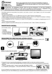
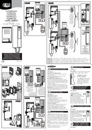
. Installation du poste de réponse<br />
1. Préparer les 3 fixations du poste de réponse 1<br />
« a, b et c ». « a et b » sont les 2 vis pour suspendre<br />
le poste et « c » l’équerre en bas au dos du poste<br />
de réponse, à démonter et à visser au mur.<br />
2. Raccorder les fils venant de la platine de rue en<br />
respectant le schéma de câblage 2<br />
3. Brancher la fiche de l’adaptateur au poste de<br />
réponse (sans le brancher sur secteur) 3<br />
4. Une fois le poste accroché au mur par « a et b »,<br />
la patte « c » à revisser sous le poste, maintiendra<br />
l’ensemble en place.<br />
5. Après s’être assuré de la finalisation de l’installation,<br />
brancher l’adaptateur sur secteur.<br />
Note : En cas de coupure du cordon d’alimentation, veillez à respecter la polarité.<br />
b. Installatie van de antwoordpost<br />
1. De 3 bevestigingen « a, b en c » van de antwoordpost 1 voorzien. « a en b » zijn de 2 schroeven<br />
om de antwoordpost op te hangen en de haak « c » onderaan aan de achterkant van de antwoordpost<br />
is te demonteren en vast te schroeven aan de muur.<br />
2. De draden afkomstig van de straatunit aansluiten volgens het draadschema 2 .<br />
3. De stekker van de adapter op de antwoordpost aansluiten (zonder aan te sluiten op het stroomnet) 3 .<br />
4. Wanneer de antwoordpost door « a en b » aan de muur is opgehangen, zal de pat « c » die onder de<br />
post zit vastgeschroefd het geheel goed op zijn plaats houden. 4. Wanneer de antwoordpost door « a<br />
en b » aan de muur is opgehangen, zal de pat « c » die onder de post zit vastgeschroefd het geheel<br />
goed op zijn plaats houden.<br />
5. Nadat de installatie volledig is uitgevoerd, de stekker van de adapter aansluiten op het stroomnet.<br />
Nota : in geval van stroomonderbreking, de polariteit in acht nemen.<br />
b. Installation der Innensprechanlage<br />
1. Die Befestigungen für Sprechstelle 1 vorbereiten „a, b, und c“. „a und b“ stellen die beiden Schrauben<br />
dar, um die Sprechstelle anzubringen und „c" den unteren Winkel auf der Rückseite der Sprechstelle, der<br />
abzubauen und an der Wand anzubringen ist.<br />
2. Die von der Außensprechanlage kommenden Drähte anschließen, dabei das Verdrahtungsschema<br />
respektieren 2 .<br />
3. Den Netzadapter mit der Innensprechanlage verbinden (noch nicht an das Stromnetz anschließen) 3<br />
4. Wenn die Sprechstelle an der Wand mit „a und b“ angebracht wurde, hält die Klammer „c“, die unter<br />
der Sprechstelle festzuschrauben ist, das Ensemble zusammen.<br />
5. Nachdem Sie sich über die Beendigung der Installation überzeugt haben, kann der Netzadapter<br />
mit dem Stromnetz verbunden werden.<br />
Anmerkung: Sollte das Stromkabel durchtrennt sein achten Sie bitte darauf, dass die Polarität respektiert wird.<br />
b. Installation of the response unit<br />
1. Prepare the three fasteners of the answering unit 1 “a, b and c”.<br />
“a and b” are the 2 screws to hang the unit and “c” the bracket at the bottom of the back of the answering<br />
unit, to be dismantled and fixed to the wall.<br />
2. Connect the wires coming from the street plate as shown in the connection plan .<br />
2<br />
3. Connect the adaptor plug to the response unit (without connecting it to the power supply) 3 .<br />
4. Once the unit is wall-mounted with “a and b”, the bracket “c” to be rescrewed under the unit will lock<br />
the assembly into place.<br />
5. After checking that installation is complete, connect the adaptor power supply plug.<br />
NB: if the power supply cable is cut, check the polarity.<br />
3 2<br />
a b<br />
1<br />
70 mm<br />
c<br />
122 mm<br />
1,60m<br />
13