Istruzioni per l'uso - Indesit.at
Istruzioni per l'uso - Indesit.at
Istruzioni per l'uso - Indesit.at

Create successful ePaper yourself
Turn your PDF publications into a flip-book with our unique Google optimized e-Paper software.
Electrical connections<br />
The cooker must be connected to the mains<br />
electricity supply. It is designed to o<strong>per</strong><strong>at</strong>e with<br />
altern<strong>at</strong>ing current <strong>at</strong> the voltage and frequency<br />
indic<strong>at</strong>ed on the d<strong>at</strong>a pl<strong>at</strong>e (see the following page).<br />
The hob is connected to the cooker using a special<br />
connector.<br />
BUILT-IN HOB<br />
Only on<br />
certain models<br />
3. Remove the wire contact screws L-N- , then<br />
fasten the wires under the screw heads, respecting<br />
the colour code: Blue (N), Brown (L) and Yellow-<br />
Green Verde ( ).<br />
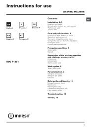
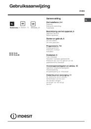
The terminal board is designed for a 400 V threephase<br />
connection (see diagrams below).<br />
N L1 L2 L3<br />
5<br />
3<br />
1<br />
400V 3N~H05RR-<br />
5x2.5 CEI-UNEL 35363<br />
GB<br />
2<br />
4<br />
P<br />
BLUE<br />
WHITE RED YELLOW<br />
GREEN<br />
N<br />
L1<br />
BUILT-IN COOKER<br />
Replace the metal protection after <strong>per</strong>forming all<br />
the necessary hob connections. If the hob is<br />
removed from its position, the red cap which was<br />
originally protecting the red connector must be<br />
replaced.<br />
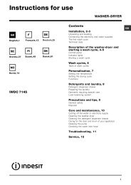
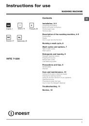
itting the power supply cable<br />
1. Open the terminal<br />
board by inserting a<br />
screwdriver into the<br />
side tabs of the cover.<br />
Use the screwdriver as<br />
a lever by pushing it<br />
down to open the cover<br />
(see diagram).<br />
If the electrical system has other characteristics (see<br />
diagrams below), carry out the electrical connection<br />
using the connection supports provided in the box<br />
P.<br />
230V ~H05RN- 3x4<br />
CEI-UNEL 35363<br />
N<br />
N<br />
5<br />
L<br />
4<br />
L2<br />
3<br />
L1 L2<br />
L3<br />
2<br />
1<br />
400V 2N~H05RR- 4x4<br />
CEI-UNEL 35363<br />
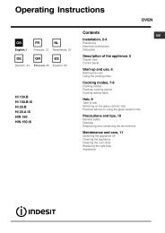
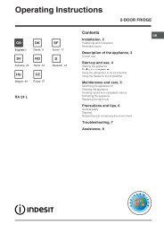
2. Loosen the cable<br />
clamp screw and<br />
remove it, using a<br />
screwdriver as a lever<br />
(see figure).<br />
5<br />
4<br />
3<br />
2<br />
1<br />
3. Secure the power supply cable by fastening the<br />
clamp screw.<br />
4. Close the cover of the terminal board.<br />
15