TD-000136-00 - QSC Audio Products
TD-000136-00 - QSC Audio Products
TD-000136-00 - QSC Audio Products

Create successful ePaper yourself
Turn your PDF publications into a flip-book with our unique Google optimized e-Paper software.
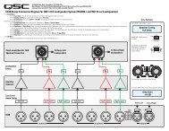
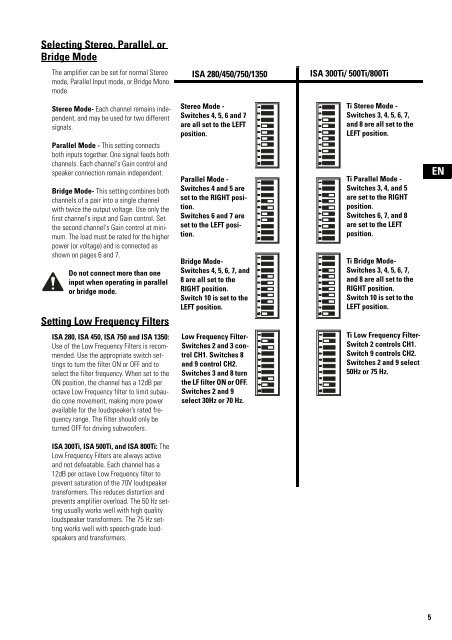
Selecting Stereo, Parallel, or<br />
Bridge Mode<br />
The amplifier can be set for normal Stereo<br />
mode, Parallel Input mode, or Bridge Mono<br />
mode.<br />
ISA 280/450/750/1350<br />
ISA 3<strong>00</strong>Ti/ 5<strong>00</strong>Ti/8<strong>00</strong>Ti<br />
Stereo Mode- Each channel remains independent,<br />
and may be used for two different<br />
signals.<br />
Parallel Mode - This setting connects<br />
both inputs together. One signal feeds both<br />
channels. Each channel's Gain control and<br />
speaker connection remain independent.<br />
Bridge Mode- This setting combines both<br />
channels of a pair into a single channel<br />
with twice the output voltage. Use only the<br />
first channel's input and Gain control. Set<br />
the second channel's Gain control at minimum.<br />
The load must be rated for the higher<br />
power (or voltage) and is connected as<br />
shown on pages 6 and 7.<br />
Do not connect more than one<br />
input when operating in parallel<br />
or bridge mode.<br />
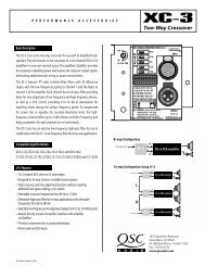
Setting Low Frequency Filters<br />
Stereo Mode -<br />
Switches 4, 5, 6 and 7<br />
are all set to the LEFT<br />
position.<br />
Parallel Mode -<br />
Switches 4 and 5 are<br />
set to the RIGHT position.<br />
Switches 6 and 7 are<br />
set to the LEFT position.<br />
Bridge Mode-<br />
Switches 4, 5, 6, 7, and<br />
8 are all set to the<br />
RIGHT position.<br />
Switch 10 is set to the<br />
LEFT position.<br />
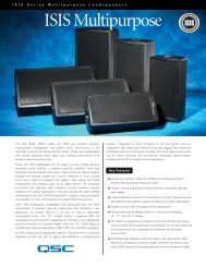
Ti Stereo Mode -<br />
Switches 3, 4, 5, 6, 7,<br />
and 8 are all set to the<br />
LEFT position.<br />
Ti Parallel Mode -<br />
Switches 3, 4, and 5<br />
are set to the RIGHT<br />
position.<br />
Switches 6, 7, and 8<br />
are set to the LEFT<br />
position.<br />
Ti Bridge Mode-<br />
Switches 3, 4, 5, 6, 7,<br />
and 8 are all set to the<br />
RIGHT position.<br />
Switch 10 is set to the<br />
LEFT position.<br />
EN<br />
ISA 280, ISA 450, ISA 750 and ISA 1350:<br />
Use of the Low Frequency Filters is recommended.<br />
Use the appropriate switch settings<br />
to turn the filter ON or OFF and to<br />
select the filter frequency. When set to the<br />
ON position, the channel has a 12dB per<br />
octave Low Frequency filter to limit subaudio<br />
cone movement, making more power<br />
available for the loudspeaker’s rated frequency<br />
range. The filter should only be<br />
turned OFF for driving subwoofers.<br />
Low Frequency Filter-<br />
Switches 2 and 3 control<br />
CH1. Switches 8<br />
and 9 control CH2.<br />
Switches 3 and 8 turn<br />
the LF filter ON or OFF.<br />
Switches 2 and 9<br />
select 30Hz or 70 Hz.<br />
Ti Low Frequency Filter-<br />
Switch 2 controls CH1.<br />
Switch 9 controls CH2.<br />
Switches 2 and 9 select<br />
50Hz or 75 Hz.<br />
ISA 3<strong>00</strong>Ti, ISA 5<strong>00</strong>Ti, and ISA 8<strong>00</strong>Ti: The<br />
Low Frequency Filters are always active<br />
and not defeatable. Each channel has a<br />
12dB per octave Low Frequency filter to<br />
prevent saturation of the 70V loudspeaker<br />
transformers. This reduces distortion and<br />
prevents amplifier overload. The 50 Hz setting<br />
usually works well with high quality<br />
loudspeaker transformers. The 75 Hz setting<br />
works well with speech-grade loudspeakers<br />
and transformers.<br />
5