TD-000136-00 - QSC Audio Products
TD-000136-00 - QSC Audio Products
TD-000136-00 - QSC Audio Products

Create successful ePaper yourself
Turn your PDF publications into a flip-book with our unique Google optimized e-Paper software.
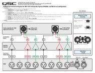
Isolated Distributed Line Outputs:<br />
ISA 3<strong>00</strong>Ti, ISA 5<strong>00</strong>Ti, and ISA 8<strong>00</strong>Ti<br />
Models Only<br />
Wiring connections are shown on the back of the chassis.<br />
STEREO and PARALLEL connections are shown on the right<br />
side of the terminals, and BRIDGE mode is shown on the<br />
left side. Carefully note the polarity marks, which are<br />
arranged to make Bridge Mode connections easier.<br />
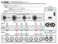
Stereo and Parallel Mode- Connect each 70V/1<strong>00</strong>V circuit<br />
to its own channel of the amplifier, as shown on the<br />
label, right of terminals. The mode configuration switches,<br />
page 6, must be set for Stereo or Parallel mode.<br />
EN<br />
Bridge Mode- Bridge mode configures the amplifier to<br />
drive a single 140V/2<strong>00</strong>V audio circuit. See page 6 to set<br />
the Bridge Mode switches. Connect a jumper wire<br />
between CH1 [0] and CH2 [0] terminals.<br />
Connect the load as shown on the label, left of the terminals.<br />
Connect only 140V/2<strong>00</strong>V distributed audio circuits in<br />
bridged mode. Use Stereo or Parallel mode channels to<br />
drive 70V loads.<br />
OUTPUT TERMINAL SAFETY WARNING! Do<br />
not touch output terminals while amplifier<br />
power is on. Make all connections with<br />
amplifier turned off. Risk of hazardous<br />
energy!<br />
WARNING! Class 2 wire shall be used. For<br />
isolated distributed 140V and 2<strong>00</strong>V, Class 3<br />
wire shall be used.<br />
70V/1<strong>00</strong>V Stereo or Parallel connection: Each 70V/<br />
1<strong>00</strong>V zone connects to its respective channel.<br />
Ensure that all speaker connections maintain<br />
proper polarity.<br />
140V/2<strong>00</strong>V Bridge connection: Wire each bridged<br />
pair to a 140V/2<strong>00</strong>V circuit as shown. Connect a<br />
jumper wire between CH1 [0] and CH2 [0] terminals.<br />
Check for proper polarity.<br />
ATTENTION! BRIDGE MODE CONNECTIONS:<br />
Connect a jumper wire between CH1 [0] and<br />
CH2 [0] terminals. The isolated output feature<br />
requires this jumper connection for bridge<br />
mode operation.<br />
DataPort<br />
The DataPort V2 connects to optional <strong>QSC</strong> accessories and<br />
processing devices. DataPort devices provide remote monitoring,<br />
DSP processing, filter and crossover functions.<br />
Amplifier Standby is not supported.<br />
If using the DataPort for input signals, do not use the Terminal<br />
Block or XLR inputs.<br />
If the amplifier is being used in a system monitored<br />
through a <strong>QSC</strong> cinema monitor (or other <strong>QSC</strong> DataPort V2<br />
supporting product) CH1 and CH2 output voltages and AC<br />
power status will be reported by the DataPort.<br />
DataPort V2 connector.<br />
NOTE! If using the DataPort<br />
V2 connection for signal<br />
input, the unused XLR or terminal<br />
block connectors may be used<br />
for daisy chaining the input signal to<br />
other amplifiers. However, note the<br />
signal will be 10 dB down from the<br />
signal applied to the DataPort.<br />
7