Bombas sumergibles de aguas fecales para servicio ... - Grundfos
Bombas sumergibles de aguas fecales para servicio ... - Grundfos
Bombas sumergibles de aguas fecales para servicio ... - Grundfos

Create successful ePaper yourself
Turn your PDF publications into a flip-book with our unique Google optimized e-Paper software.
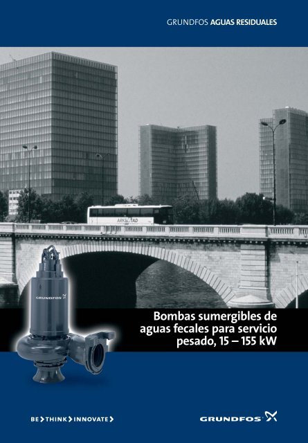
GRUNDFOS AGUAS RESIDUALES<br />
<strong>Bombas</strong> <strong>sumergibles</strong> <strong>de</strong><br />
<strong>aguas</strong> <strong>fecales</strong> <strong>para</strong> <strong>servicio</strong><br />
pesado, 15 – 155 kW
<strong>Grundfos</strong><br />
<strong>Bombas</strong> gran<strong>de</strong>s muy eficientes <strong>para</strong><br />
manejar <strong>aguas</strong> <strong>fecales</strong> sin tratar<br />
<strong>Grundfos</strong> ofrece una gama completa <strong>de</strong> bombas<br />
<strong>de</strong> <strong>aguas</strong> <strong>fecales</strong>, extremadamente seguras y muy<br />
eficientes, diseñadas <strong>para</strong> manejar <strong>aguas</strong> <strong>fecales</strong><br />
sin tratar. Tenemos más <strong>de</strong> 40 años <strong>de</strong> experiencia<br />
como proveedores <strong>de</strong> bombas y equipos <strong>de</strong><br />
bombeo, diseñados específicamente <strong>para</strong><br />
bombear todo tipo <strong>de</strong> <strong>aguas</strong> residuales y <strong>fecales</strong>,<br />
por lo que sabemos lo que nuestros clientes<br />
exigen <strong>de</strong> una bomba <strong>de</strong> <strong>aguas</strong> <strong>fecales</strong>:<br />
Beneficios excepcionales<br />
> Mayor rendimiento <strong>de</strong> la bomba durante<br />
toda su vida<br />
El diseño <strong>de</strong> tecnología punta consigue que las<br />
bombas <strong>Grundfos</strong> sean extremadamente seguras<br />
y muy eficientes. Características innovadoras,<br />
tales como el excepcional ajuste SmartTrim <strong>de</strong> la<br />
holgura <strong>de</strong>l impulsor, proporcionan unos bajos<br />
costes <strong>de</strong> propiedad.<br />
> Menos tiempo <strong>de</strong> inactividad<br />
La excelente capacidad <strong>de</strong> nuestras bombas <strong>de</strong><br />
impulsor <strong>de</strong> canal <strong>para</strong> manejar sólidos<br />
garantiza un tiempo máximo <strong>de</strong><br />
funcionamiento y reducciones sustanciales <strong>de</strong><br />
los costes <strong>de</strong> mantenimiento, ocasionados por<br />
atascos o agarrotamiento <strong>de</strong> las bombas.<br />
> Fiabilidad durante una larga vida <strong>de</strong><br />
bombeo<br />
Las robustas bombas <strong>de</strong> <strong>aguas</strong> <strong>fecales</strong> están<br />
diseñadas <strong>para</strong> bombeo continuo en<br />
condiciones <strong>de</strong> trabajo extremadamente<br />
<strong>de</strong>sfavorables. El diseño está basado en nuestra<br />
larga experiencia en el campo <strong>de</strong> <strong>aguas</strong><br />
residuales.<br />
En <strong>Grundfos</strong> siempre estamos en estrecho<br />
contacto con nuestros clientes, lo que nos<br />
permite mejorar constantemente el diseño y<br />
funcionamiento <strong>de</strong> las bombas. Sólo así<br />
po<strong>de</strong>mos establecer unas relaciones comerciales<br />
dura<strong>de</strong>ras, que son la base <strong>de</strong> nuestro negocio.<br />
2<br />
>
Opciones <strong>de</strong> instalación<br />
Instalación sumergida con autoacoplamiento, tipos 1 y 2<br />
La instalación sumergida con un sistema <strong>de</strong> autoacoplamiento requiere una base<br />
con codo <strong>de</strong> 90°, fijada en el fondo <strong>de</strong> la fosa. Después <strong>de</strong> bajar la bomba a la fosa<br />
mediante los tubos guía, ésta queda automáticamente conectada a la base. El<br />
flexible SmartSeal <strong>de</strong> neopreno garantiza una conexión hermética entre la bomba<br />
y el autoacoplamiento.<br />
Tipo 1:<br />
Para evitar sedimentación <strong>de</strong> lodos cuando el funcionamiento sea intermitente<br />
recomendamos un nivel <strong>de</strong> <strong>para</strong>da que corresponda al extremo superior <strong>de</strong>l cuerpo<br />
<strong>de</strong> la bomba. Con el fin <strong>de</strong> tener una refrigeración suficiente cuando el<br />
funcionamiento sea continuo, el nivel <strong>de</strong>l líquido <strong>de</strong>be estar siempre por encima <strong>de</strong><br />
la mitad <strong>de</strong>l motor.<br />
Tipo 2:<br />
La refrigeración <strong>de</strong>l motor es in<strong>de</strong>pendiente <strong>de</strong>l líquido <strong>de</strong> bombeo, gracias a su<br />
refrigeración interna (mediante camisa <strong>de</strong> refrigeración).<br />
Instalación vertical en seco, tipo 3<br />
Las bombas <strong>de</strong> <strong>aguas</strong> <strong>fecales</strong> <strong>Grundfos</strong> pue<strong>de</strong>n instalarse tanto en posición vertical<br />
como horizontal <strong>para</strong> ajustarse a aplicaciones específicas. Todas las bombas son<br />
estancas al 100 %, lo que permite instalación en seco con un espacio <strong>de</strong> trabajo<br />
limpio y seco alre<strong>de</strong>dor <strong>de</strong> la bomba. Las bombas están completamente a prueba<br />
<strong>de</strong> inundaciones inesperadas.<br />
La refrigeración <strong>de</strong>l motor se realiza mediante una camisa <strong>de</strong> refrigeración.<br />
Instalación sumergida portátil, tipos 4 y 5<br />
Algunas aplicaciones, tales como zonas <strong>de</strong> construcción, requieren bombas<br />
<strong>sumergibles</strong> portátiles. Don<strong>de</strong> se necesita una bomba sumergible portátil pue<strong>de</strong>n<br />
pedirse mangueras <strong>de</strong> distintas longitu<strong>de</strong>s y materiales.<br />
Tipo 4:<br />
Para evitar sedimentación <strong>de</strong> lodos cuando el funcionamiento sea intermitente<br />
recomendamos un nivel <strong>de</strong> <strong>para</strong>da que corresponda al extremo superior <strong>de</strong>l cuerpo<br />
<strong>de</strong> la bomba. Con el fin <strong>de</strong> tener una refrigeración suficiente cuando el<br />
funcionamiento sea continuo, el nivel <strong>de</strong>l líquido <strong>de</strong>be estar siempre por encima <strong>de</strong><br />
la mitad <strong>de</strong>l motor.<br />
Tipo 5:<br />
La refrigeración <strong>de</strong>l motor es in<strong>de</strong>pendiente <strong>de</strong>l líquido <strong>de</strong> bombeo, gracias a la<br />
refrigeración interna <strong>de</strong>l motor.<br />
Instalación horizontal en seco, tipo 6<br />
La instalación horizontal en seco aumenta el rendimiento total <strong>de</strong>l sistema, ya que<br />
se evitan componentes y codos innecesarios. La posibilidad <strong>de</strong> instalación<br />
horizontal en seco <strong>de</strong>pen<strong>de</strong> <strong>de</strong>l espacio <strong>de</strong> suelo disponible, ya que el sistema ocupa<br />
un poco más espacio que una bomba <strong>de</strong> instalación vertical.<br />
La refrigeración <strong>de</strong>l motor se realiza mediante una camisa <strong>de</strong> refrigeración.<br />
3<br />
>
<strong>Bombas</strong> resistentes y seguras...<br />
Las bombas <strong>sumergibles</strong> <strong>de</strong> <strong>aguas</strong> <strong>fecales</strong> <strong>Grundfos</strong> están diseñadas <strong>para</strong><br />
reducir el consumo <strong>de</strong> energía y mantener al mínimo los costes ocasionados<br />
por periodos <strong>de</strong> inactividad. Es <strong>de</strong> suma importancia mantener el<br />
rendimiento máximo a lo largo <strong>de</strong> toda la vida <strong>de</strong>l sistema:<br />
Motor encapsulado hermético,<br />
clase <strong>de</strong> aislamiento F (155° C),<br />
grado <strong>de</strong> protección IP 68, con tres<br />
sensores térmicos en los<br />
bobinados <strong>de</strong>l estator.<br />
Doble cojinete inferior. Algunos<br />
mo<strong>de</strong>los tienen un cojinete radial<br />
adicional.<br />
Control <strong>de</strong>l estado <strong>de</strong>l cierre. Una sonda <strong>de</strong><br />
control en la cámara <strong>de</strong> aceite da aviso<br />
inmediato <strong>de</strong> fugas <strong>de</strong>l cierre (opcional).<br />
El sistema <strong>de</strong> junta<br />
SmartSeal <strong>Grundfos</strong><br />
proporciona una conexión<br />
completamente hermética.<br />
Sistema <strong>de</strong> doble cierre mecánico en<br />
la cámara <strong>de</strong> aceite intermedia <strong>para</strong><br />
sellado seguro entre el líquido<br />
bombeado y el motor. Cierre primario<br />
con anillos SiC/SiC (Carburo <strong>de</strong> Silicio<br />
en ambas caras) y anillos SiC/carbono<br />
en el cierre secundario.<br />
4
– con muchas características excepcionales<br />
Entrada <strong>de</strong> cable estanca<br />
<strong>de</strong> poliamida resistente a<br />
la corrosión, o fundición<br />
con bor<strong>de</strong>s suaves <strong>para</strong><br />
evitar daños al cable<br />
eléctrico.<br />
<strong>Bombas</strong> <strong>Grundfos</strong><br />
instaladas en seco en<br />
posición horizontal o<br />
vertical llevan camisa <strong>de</strong><br />
refrigeración. (Ver la<br />
página 7 <strong>para</strong> más<br />
información.)<br />
Detector <strong>de</strong> humedad que<br />
controla <strong>de</strong> forma continua<br />
la protección <strong>de</strong>l motor y<br />
<strong>de</strong>sconecta<br />
automáticamente la<br />
corriente en el caso <strong>de</strong><br />
fugas.<br />
Eje <strong>de</strong> bomba en acero<br />
inoxidable equilibrado<br />
dinámicamente y<br />
completamente protegido<br />
contra contacto con el líquido<br />
bombeado. Extremo <strong>de</strong> eje<br />
cónico <strong>para</strong> una sujeción<br />
segura <strong>de</strong>l impulsor.<br />
Sistema SmartTrim que<br />
permite un ajuste fácil <strong>de</strong><br />
la holgura <strong>de</strong>l impulsor,<br />
ajustada en fábrica,<br />
manteniendo el<br />
rendimiento máximo <strong>de</strong> la<br />
bomba.<br />
5<br />
Detalles >
Avanzada tecnología <strong>de</strong> cierres mecánicos<br />
excavada en una sólida roca <strong>de</strong> granito, 30 metros<br />
bajo tierra. Es el punto <strong>de</strong> captación <strong>de</strong> las <strong>aguas</strong><br />
<strong>fecales</strong> <strong>de</strong>l centro <strong>de</strong> Helsinki y está diseñada <strong>para</strong><br />
manejar 93.000 m 3 /día. Incorpora cuatro bombas <strong>de</strong><br />
<strong>aguas</strong> <strong>fecales</strong> <strong>Grundfos</strong> <strong>de</strong> 130 kW, instaladas en seco<br />
en posición horizontal, con camisas <strong>de</strong> refrigeración.<br />
La instalación horizontal resulta ventajosa, ya que<br />
facilita la instalación <strong>de</strong> las tuberías. Esta instalación<br />
ofrece una fluidodinámica mejorada, lo que permite<br />
un funcionamiento más suave <strong>de</strong> la bomba, gracias a<br />
la aspiración uniforme <strong>de</strong>l impulsor.<br />
30 m <strong>de</strong> reflujo sin válvulas <strong>de</strong><br />
retención<br />
La estación <strong>de</strong> bombeo <strong>de</strong> Mäntymäki, Finlandia, está<br />
consi<strong>de</strong>rada el mayor paso hacia <strong>de</strong>lante en la<br />
mo<strong>de</strong>rnización <strong>de</strong>l tratamiento <strong>de</strong> <strong>aguas</strong> <strong>fecales</strong> <strong>de</strong> la<br />
ciudad. El proyecto está dirigido al gran crecimiento<br />
<strong>de</strong> la población <strong>de</strong> la ciudad y, por lo tanto, mayores<br />
<strong>de</strong>mandas en la infraestructura existente.<br />
La estación <strong>de</strong> bombeo <strong>de</strong> Mäntymäki ha sido<br />
Una característica interesante <strong>de</strong> esta aplicación es la<br />
falta <strong>de</strong> válvulas <strong>de</strong> retención. Cuando las bombas se<br />
<strong>para</strong>n, toda la columna <strong>de</strong> agua fluye <strong>de</strong> vuelta a<br />
través <strong>de</strong> las bombas, lo que sirve <strong>para</strong> limpiar las<br />
mismas, así como la cámara <strong>de</strong> aspiración. Se<br />
eliminan los atascos y la sedimentación, tanto en la<br />
superficie como en el fondo, sin ninguna intervención<br />
manual. Las cuatro bombas llevan el excepcional<br />
sistema SmartTrim <strong>de</strong> ajuste <strong>de</strong>l impulsor<br />
Limpieza automática <strong>de</strong> fosas húmedas<br />
Los cierres <strong>de</strong> las bombas <strong>Grundfos</strong> pue<strong>de</strong>n girar en<br />
cualquier sentido. Cuando se instalen con tuberías<br />
se<strong>para</strong>das pue<strong>de</strong> evitarse eficazmente la<br />
sedimentación <strong>de</strong> lodos, limpiando el sistema en<br />
sentido contrario a intervalos regulares.<br />
Vida más larga <strong>de</strong> la bomba<br />
Muelles situados <strong>de</strong>ntro <strong>de</strong> la cámara <strong>de</strong> aceite<br />
garantizan un funcionamiento ininterrumpido <strong>de</strong>l<br />
cierre. Los muelles están completamente aislados <strong>de</strong>l<br />
líquido <strong>de</strong> bombeo. La eliminación automática <strong>de</strong> aire<br />
y partículas <strong>de</strong>l área <strong>de</strong>l cierre, junto con caras <strong>de</strong>l<br />
cierre primario <strong>de</strong> carburo <strong>de</strong> silicio, es la mejor<br />
garantía <strong>de</strong> un funcionamiento ininterrumpido y una<br />
vida más larga <strong>de</strong> la bomba.<br />
Reducción <strong>de</strong> los costes <strong>de</strong> instalación <strong>para</strong><br />
fosas en seco<br />
En estaciones <strong>de</strong> bombeo con tuberías se<strong>para</strong>das<br />
<strong>para</strong> cada bomba no se necesitan costosas válvulas<br />
<strong>de</strong> retención.<br />
6<br />
Cierre >
Condiciones <strong>de</strong> funcionamiento<br />
Refrigeración eficaz <strong>de</strong> motores<br />
en instalaciones en seco<br />
Para aplicaciones en seco, una refrigeración<br />
eficaz <strong>de</strong>l motor es esencial. Esto se consigue<br />
mediante una camisa <strong>de</strong> refrigeración que cubre<br />
el alojamiento <strong>de</strong>l estator.<br />
El líquido <strong>de</strong> refrigeración es llevado a la camisa<br />
<strong>de</strong> refrigeración a través <strong>de</strong> un paso libre por<br />
<strong>de</strong>trás <strong>de</strong>l impulsor. Un sistema <strong>de</strong> filtrado<br />
integrado impi<strong>de</strong> que los sólidos entren en la<br />
camisa <strong>de</strong> refrigeración.<br />
En el arranque, la camisa <strong>de</strong> refrigeración se<br />
llena automáticamente con el líquido <strong>de</strong><br />
bombeo filtrado. Funciona como un circuito<br />
cerrado y <strong>de</strong>vuelve el exceso <strong>de</strong> calor <strong>de</strong>l motor<br />
al líquido bombeado.<br />
Condiciones <strong>de</strong> funcionamiento<br />
La utilización <strong>de</strong> las bombas está limitada como<br />
se indica a continuación:<br />
• Temperatura ambiente y temperatura <strong>de</strong>l<br />
líquido <strong>de</strong> bombeo máx.: +40°C<br />
• Temperatura <strong>de</strong> almacenaje –30°C a +60°C<br />
• Sumersión máx.: 20 m<br />
• Tolerancia <strong>de</strong> tensión <strong>para</strong> motores <strong>de</strong><br />
3 x 400 V<br />
50 Hz : ± 10 %<br />
Frecuencia máxima <strong>de</strong> arranques<br />
La frecuencia <strong>de</strong> arranques no <strong>de</strong>be superar los 15<br />
arranques a la hora. Durante breves periodos se<br />
permite una frecuencia <strong>de</strong> arranques <strong>de</strong> hasta el<br />
doble <strong>de</strong> la recomendada.<br />
<strong>Bombas</strong> <strong>de</strong> instalación horizontal con camisa <strong>de</strong><br />
refrigeración<br />
<strong>Bombas</strong> <strong>de</strong> instalación vertical con camisa <strong>de</strong><br />
refrigeración<br />
7<br />
Motor >
Diseño eficaz <strong>de</strong>l impulsor<br />
Amplio paso libre <strong>para</strong> mejor<br />
manejo <strong>de</strong> sólidos<br />
El comprometer la capacidad <strong>de</strong> manejar sólidos<br />
<strong>para</strong> conseguir un mayor rendimiento <strong>de</strong> bombeo<br />
aumenta consi<strong>de</strong>rablemente el riesgo <strong>de</strong> atascos.<br />
Más atascos significan más tiempo <strong>de</strong> inactividad<br />
y mayores costes <strong>de</strong> funcionamiento.<br />
Las bombas <strong>de</strong> impulsor <strong>de</strong> canal <strong>Grundfos</strong><br />
pue<strong>de</strong>n bombear sólidos <strong>de</strong> hasta Ø 145 mm. No<br />
obstante, el paso libre completo es mucho mayor,<br />
lo que significa menos atascos y menos tiempo<br />
<strong>de</strong> inactividad.<br />
Diseño <strong>de</strong> impulsor semiaxial con<br />
álabes largos<br />
La longitud <strong>de</strong> un álabe <strong>de</strong> impulsor es un factor<br />
clave a la hora <strong>de</strong> <strong>de</strong>terminar la longitud <strong>de</strong> las<br />
fibras que pue<strong>de</strong>n atravesar la bomba sin<br />
atascarse. Los impulsores <strong>de</strong> canal <strong>Grundfos</strong><br />
tienen un diseño semiaxial con álabes muy<br />
largos, lo que proporciona un rendimiento<br />
máximo y elimina los problemas con fibras<br />
atascadas en el impulsor.<br />
Diseño inatascable <strong>de</strong>l álabe <strong>de</strong><br />
impulsor<br />
Los impulsores convencionales <strong>de</strong> doble canal<br />
son susceptibles a atascos, ya que las partículas<br />
fibrosas tien<strong>de</strong>n a entrar en ambos canales y<br />
quedar atascadas en el bor<strong>de</strong> <strong>de</strong>lantero. Pero<br />
este problema está prácticamente eliminado<br />
gracias al diseño rebajado <strong>de</strong>l bor<strong>de</strong> <strong>de</strong>lantero<br />
<strong>de</strong>l impulsor <strong>de</strong> doble canal.<br />
Este diseño especial <strong>de</strong> los impulsores <strong>de</strong> doble<br />
canal, probado en condiciones reales, junto con<br />
un paso libre <strong>de</strong> mín. 100 mm, significa que los<br />
impulsores <strong>de</strong> doble canal <strong>Grundfos</strong> pue<strong>de</strong>n<br />
manejar <strong>aguas</strong> <strong>fecales</strong> sin tratar en aplicaciones<br />
<strong>de</strong> <strong>servicio</strong> pesado. El rendimiento máximo es<br />
<strong>de</strong>l 80-85%.<br />
8<br />
Impulsores <strong>de</strong> canal >
Impulsores SmartTrim <strong>Grundfos</strong><br />
Posición <strong>de</strong>l sistema SmartTrim <strong>para</strong> bombas <strong>de</strong> instalación<br />
horizontal en seco<br />
Posición <strong>de</strong>l sistema SmartTrim en bombas sumergidas en<br />
posición vertical<br />
Ajuste SmartTrim <strong>de</strong> la<br />
holgura <strong>de</strong>l impulsor<br />
Las bombas <strong>Grundfos</strong> <strong>de</strong> <strong>aguas</strong> <strong>fecales</strong> <strong>para</strong><br />
<strong>servicio</strong> pesado están diseñadas <strong>para</strong> reducir el<br />
consumo <strong>de</strong> energía y mantener los costes <strong>de</strong><br />
funcionamiento al mínimo. Por lo tanto, el<br />
mantenimiento <strong>de</strong>l rendimiento máximo <strong>de</strong><br />
bombeo a lo largo <strong>de</strong> toda la vida <strong>de</strong>l sistema es <strong>de</strong><br />
suma importancia.<br />
La arena, guijarros y otros abrasivos <strong>de</strong>sgastan el<br />
impulsor <strong>de</strong> cualquier bomba. A consecuencia, la<br />
holgura <strong>de</strong>l impulsor aumenta y se reduce el<br />
rendimiento <strong>de</strong> la bomba. Una mayor holgura <strong>de</strong>l<br />
impulsor significa más fugas <strong>de</strong> reflujo y mayor<br />
riesgo <strong>de</strong> atascos.<br />
Sistema SmartTrim<br />
– rápido, fácil y eficaz<br />
En las bombas convencionales el mantenimiento<br />
<strong>de</strong> la holgura <strong>de</strong>l impulsor, ajustada en fábrica, es<br />
una tarea laboriosa y costosa. Las bombas <strong>de</strong>ben<br />
<strong>de</strong>sconectarse <strong>de</strong> la tubería y <strong>de</strong>smontarse por<br />
completo, y hay que montar piezas nuevas <strong>para</strong><br />
mantener el rendimiento completo <strong>de</strong> bombeo.<br />
¡Esto no ocurre con el SmartTrim <strong>de</strong> <strong>Grundfos</strong>!<br />
Todas las bombas <strong>sumergibles</strong> <strong>de</strong> impulsor <strong>de</strong><br />
canal <strong>Grundfos</strong>, tanto <strong>para</strong> instalación sumergida<br />
como en seco, incorporan el sistema excepcional <strong>de</strong><br />
ajuste <strong>de</strong> la holgura <strong>de</strong>l impulsor SmartTrim. Este<br />
permite recuperar la holgura <strong>de</strong>l impulsor ajustada<br />
en fábrica y mantener el rendimiento máximo <strong>de</strong><br />
bombeo. Sólo hay que apretar los tornillos <strong>de</strong><br />
ajuste en la parte exterior <strong>de</strong>l alojamiento <strong>de</strong>l<br />
impulsor, lo que pue<strong>de</strong> hacerse fácil y rápidamente<br />
in situ, sin necesidad <strong>de</strong> herramientas especiales.<br />
Reducción <strong>de</strong>l<br />
rendimiento en %<br />
0<br />
3<br />
6<br />
9<br />
12<br />
15<br />
A<br />
B<br />
Años<br />
1<br />
Holgura <strong>de</strong>l impulsor ajustada en fábrica<br />
2 3 4 5<br />
Con sistema <strong>de</strong> ajuste <strong>de</strong> la hogura <strong>de</strong>l impulsor SmartTrim <strong>Grundfos</strong><br />
Sin sistema <strong>de</strong> ajuste <strong>de</strong> la holgura <strong>de</strong>l impusor<br />
A<br />
B<br />
9<br />
Impulsores SmartTrim >
Gama <strong>de</strong> trabajo y nomenclatura<br />
Gama <strong>de</strong> trabajo – gama <strong>de</strong> bombas <strong>sumergibles</strong> <strong>de</strong> <strong>aguas</strong> <strong>fecales</strong> <strong>Grundfos</strong><br />
H [m]<br />
100<br />
80<br />
60<br />
7<br />
50 Hz<br />
40<br />
30<br />
5<br />
4<br />
9<br />
20<br />
6<br />
10<br />
8<br />
1<br />
3<br />
8<br />
6<br />
4<br />
2<br />
3<br />
2<br />
5 10 20 30 40 60 80 100 200 300 400 60 0 1000 2000 3000<br />
Q [l/s]<br />
20 40 60 80 100 200 400 600 1000 2000 4000<br />
Q [m 3 /h]<br />
Área<br />
Descripción<br />
Nomenclatura<br />
1 Poca altura,<br />
gamas 58 y 62<br />
2 Poca altura, hidráulica E<br />
gamas 58 y 62<br />
3 Poca altura,<br />
gamas 66 y 70<br />
4 Poca altura y altura media,<br />
gamas 66 y 70<br />
5 Altura media y gran<strong>de</strong>,<br />
gamas 58 y 62<br />
6 Altura media y gran<strong>de</strong>,<br />
gamas 66 y 70<br />
7 Altura gran<strong>de</strong> y super gran<strong>de</strong>,<br />
gamas 66 y 70<br />
8 Impulsor SuperVortex y bombas <strong>de</strong> impulsor <strong>de</strong> canal,<br />
1.65 kW a 29 kW*<br />
9 <strong>Bombas</strong> <strong>de</strong> impulsor <strong>de</strong> canal, 160 kW a 520 kW*<br />
* Ver folleto se<strong>para</strong>do<br />
¡Nota!<br />
Los datos y las curvas en las páginas 11 – 14 sólo se refieren a bombas en el<br />
tipo <strong>de</strong> instalación 1 (instalación sumergida con base y codo). Los datos y<br />
curvas <strong>para</strong> otros tipos <strong>de</strong> instalación, así como <strong>para</strong> bombas<br />
anti<strong>de</strong>flagrantes, pue<strong>de</strong>n variar. Consultar con <strong>Grundfos</strong> <strong>para</strong> más<br />
información o visitar nuestra página web www.grundfos.com.<br />
Ejemplo S2 304 AL1 S 2 30 4 A L 1<br />
Bomba <strong>de</strong> <strong>aguas</strong> <strong>fecales</strong><br />
Tipo <strong>de</strong> impulsor<br />
1 = Monocanal<br />
2 = dos canales<br />
3 = Tres canales<br />
Versión<br />
Blanco = Motor no anti<strong>de</strong>flagrante<br />
X = Motor anti<strong>de</strong>flagrante<br />
Potencia nominal <strong>de</strong>l motor P N en kW<br />
Número <strong>de</strong> polos<br />
Generación <strong>de</strong> bomba<br />
Clasificación <strong>de</strong> altura<br />
E = Muy poca altura L = Poca altura M = Altura media<br />
H = Gran altura S = Super-gran altura<br />
Tipo <strong>de</strong> instalación<br />
1 =Instalación sumergida con autoacoplamiento<br />
2 =Instalación sumergida con autoacoplamiento<br />
Refrigeración <strong>de</strong>l motor in<strong>de</strong>pendiente <strong>de</strong>l nivel <strong>de</strong>l<br />
líquido <strong>de</strong> bombeo. Ver pág. 7<br />
3 =Instalación vertical en seco<br />
4 =Instalación sumergida, portátil<br />
5 =Instalación sumergida, portátil<br />
Refrigeración <strong>de</strong>l motor in<strong>de</strong>pendiente <strong>de</strong>l nivel <strong>de</strong>l<br />
líquido <strong>de</strong> bombeo. Ver pág. 7<br />
6 =Instalación horizontal en seco<br />
10<br />
Datos técnicos >
Datos técnicos<br />
Poca altura, gamas 58 y 62 Poca altura, hidráulica E, gamas 58 y 62<br />
H[m]<br />
34<br />
32<br />
30<br />
28<br />
8<br />
7<br />
S2, S3<br />
50 Hz<br />
ISO 9906 Anexo A<br />
H [m]<br />
20<br />
18<br />
S2<br />
50 Hz<br />
ISO 9906 Anexo A<br />
26<br />
16<br />
24<br />
22<br />
20<br />
18<br />
16<br />
14<br />
12<br />
10<br />
8<br />
6<br />
6<br />
5<br />
4<br />
3<br />
2<br />
1<br />
14<br />
12<br />
10<br />
8<br />
6<br />
4<br />
9 10 11 12 13<br />
4<br />
2<br />
2<br />
0<br />
0 40 80 120 160 200 240 280 320 360 400<br />
Q [l/s]<br />
0<br />
0 40 80 120 160 200 240 280 320 360<br />
Q [l/s]<br />
0 200 400 600 800 1000 1200 1400<br />
Q [m 3 /h]<br />
0 200 400 600 800 1000 1200<br />
Q [m 3 /h]<br />
Datos eléctricos y técnicos<br />
No.<br />
Tipo <strong>de</strong><br />
bomba<br />
Curva <strong>de</strong> bomba<br />
Gama Tamaño máx.<br />
bomba sólidos [mm]<br />
Instalación<br />
sumergida<br />
Salida<br />
[mm]<br />
Peso<br />
[kg]<br />
Instalación en seco<br />
Entrada<br />
DN<br />
Instalación<br />
sumergida, portátil<br />
1 S3 1512 62 Ø 120 Ø 300 860 400 Ø 300 860 - - 15.0 490<br />
2 S2 208 62 Ø 145 Ø 300 780 400 Ø 300 780 - - 20.0 740<br />
3 S2 288 62 Ø 145 Ø 300 900 400 Ø 300 900 - - 28.0 730<br />
4 S2 224 AL 58 Ø 100 Ø 200 510 250 Ø 200 510 Ø 200 510 22.0 1460<br />
5 S2 304 AL 62 Ø 100 Ø 200 650 250 Ø 200 650 - - 30.0 1480<br />
6 S2 264 AL 58 Ø 100 Ø 200 510 250 Ø 200 510 Ø 200 510 26.0(28.0) 1450<br />
7 S2 404 AL 62 Ø 100 Ø 200 695 250 Ø 200 695 - - 41.0(43.0) 1460<br />
8 S2 504 AL 62 Ø 100 Ø 200 720 250 Ø 200 720 - - 50.0 1470<br />
9 S2 156 E 58 Ø 100 Ø 300 600 250 Ø 300 600 Ø 300 600 16.0 970<br />
10 S2 226 E 58 Ø 100 Ø 300 590 250 Ø 300 590 Ø 300 590 22.5 960<br />
11 S2 304 E 62 Ø 100 Ø 300 660 250 Ø 300 660 - - 30.0 1480<br />
12 S2 404 E 62 Ø 100 Ø 300 725 250 Ø 300 725 - - 41.0(43.0) 1460<br />
13 S2 504 E 62 Ø 100 Ø 300 780 250 Ø 300 780 - - 50.0 1470<br />
(): Los datos <strong>de</strong>l motor entre paréntesis se refieren a instalaciones 2, 3, 5 y 6<br />
Salida<br />
DN<br />
Peso<br />
[kg]<br />
Manguera<br />
[mm]<br />
Peso<br />
[kg]<br />
P N<br />
[kW]<br />
nN<br />
[min -1 ]<br />
Motor<br />
I N 400 V<br />
[A]<br />
IS/I N<br />
37.0 4.0<br />
41.0 6.6<br />
55.0 4.9<br />
44.0 6.1<br />
67.0 6.9<br />
50.2(55.6) 5.2(4.7)<br />
84.7(87.0) 5.8(5.6)<br />
101.4 5.2<br />
38.2 5.5<br />
48.6 4.3<br />
67.0 6.9<br />
84.7(87.0) 5.8(5.6)<br />
101.4 5.2<br />
Gama <strong>de</strong> bomba, concepto modular<br />
Las bombas <strong>de</strong> <strong>aguas</strong> <strong>fecales</strong> <strong>para</strong> <strong>servicio</strong> pesado <strong>Grundfos</strong> tienen diseño modular, lo que significa que<br />
bombas que pertenecen a la misma gama comparten muchos repuestos comunes, por lo que pue<strong>de</strong>n<br />
intercambiarse impulsores y otros componentes hidráulicos.<br />
11<br />
Datos técnicos >
Datos técnicos<br />
Poca altura, gamas 66 y 70 Poca altura y altura media, gamas 66 y 70<br />
H [m]<br />
28<br />
26<br />
24<br />
22<br />
20<br />
18<br />
16<br />
14<br />
12<br />
10<br />
8<br />
6<br />
4<br />
2<br />
0<br />
7 8 9 10<br />
1 2 3 4 5 6<br />
0 100 200 300 400 500 600 700 800 900 Q [l/s]<br />
S3<br />
S3<br />
50 Hz50 Hz<br />
ISO 9906 Anexo A<br />
ISO 9906 Annex A<br />
H [m]<br />
75 S2<br />
50 Hz<br />
70<br />
ISO 9906 Anexo A<br />
65<br />
60<br />
55<br />
50<br />
45<br />
40<br />
35<br />
14 15 16 17<br />
30<br />
25<br />
20<br />
15<br />
10<br />
11 12 13<br />
5<br />
0<br />
0 50 100 150 200 250 300 350 400 450 Q [l/s]<br />
0 500 1000 1500 2000 2500 3000<br />
Q [m 3 /h]<br />
0 500 1000 1500<br />
Q [m 3 /h]<br />
Datos eléctricos y técnicos<br />
No.<br />
Tipo <strong>de</strong><br />
bomba<br />
Curva <strong>de</strong> bomba<br />
Gama Tamaño máx.<br />
bomba solidos [mm]<br />
Instalación<br />
sumergida<br />
Salida<br />
[mm]<br />
Peso<br />
[kg]<br />
Entrada<br />
DN<br />
Instalación en seco<br />
Instalación<br />
sumergida, portátil<br />
1 S3 2210 L 66 115x140 Ø 500 830 500 Ø 500 830 - - 22.0 590<br />
2 S3 3510 E 66 125x163 Ø 600 1000 500 Ø 600 1000 - - 35.0 590<br />
3 S3 3510 L 66 115x140 Ø 500 1000 500 Ø 500 1000 - - 35.0 580<br />
4 S3 508 L 66 115x140 Ø 500 1300 500 Ø 500 1300 - - 50.0 730<br />
5 S3 508 E 66 125x163 Ø 600 1400 500 Ø 600 1400 - - 50.0 730<br />
6 S3 658 E 70 125x163 Ø 600 1700 500 Ø 600 1700 - - 65.0 730<br />
7 S3 658 L 70 115x140 Ø 500 1590 500 Ø 500 1590 - - 65.0 730<br />
8 S3 1006 L 70 115x140 Ø 500 1870 500 Ø 500 1870 - - 100.0 980<br />
9 S3 1306 E 70 125x163 Ø 600 2000 500 Ø 600 2000 - - 130.0 980<br />
10 S3 1306 L 70 115x140 Ø 500 1830 500 Ø 500 1830 - - 130.0 980<br />
11 S2 554 BM 66 Ø 100 Ø 200 760 250 Ø 200 760 - - 58.0 1480<br />
12 S2 654 BM 66 Ø 100 Ø 200 840 250 Ø 200 840 - - 68.0 1480<br />
13 S2 654 AL 66 110x130 Ø 250 840 300 Ø 250 840 - - 68.0 1480<br />
14 S2 854 AM 70 Ø 100 Ø 200 1090 250 Ø 200 1090 - - 85.0 1480<br />
15 S2 1154 M 70 100x110 Ø 200 1480 250 Ø 200 1480 - - 115.0 1480<br />
16 S2 1604 M 70 100x110 Ø 200 1350 250 Ø 200 1350 - - 155.0 1480<br />
17 S2 1604 L 70 Ø 110 Ø 250 1430 300 Ø 250 1430 - - 155.0 1480<br />
Salida<br />
DN<br />
Peso<br />
[kg]<br />
manguera<br />
[mm]<br />
Peso<br />
[kg]<br />
PN<br />
[kW]<br />
nN<br />
[min -1 ]<br />
Motor<br />
I N 400 V<br />
[A]<br />
IS/IN<br />
55.0 5.1<br />
79.5 4.7<br />
79.5 4.7<br />
101.2 5.4<br />
101.2 5.4<br />
129.0 5.2<br />
121.0 6.1<br />
121.0 6.1<br />
249.3 7.9<br />
249.3 7.9<br />
116.4 7.2<br />
134.9 6.3<br />
134.9 6.3<br />
152.9 6.8<br />
210.0 6.8<br />
278.0 7.5<br />
278.0 7.5<br />
12<br />
Datos técnicos >
Altura media y gran<strong>de</strong>, gamas 58 y 62 Altura media y gran<strong>de</strong>, gamas 66 y 70<br />
H [m]<br />
H [m]<br />
70<br />
65<br />
60<br />
55<br />
50<br />
45<br />
5 8 9 10<br />
S1<br />
50 Hz<br />
ISO 9906 Anexo A<br />
48<br />
44<br />
40<br />
36<br />
32<br />
19 20 21<br />
S2, S3<br />
50 Hz<br />
ISO 9906 Anexo A<br />
40<br />
28<br />
35<br />
24<br />
30<br />
2 4<br />
3<br />
6<br />
7<br />
20<br />
25<br />
20<br />
15<br />
10<br />
1<br />
16<br />
12<br />
8<br />
17 18 14 15<br />
16<br />
11 12 13<br />
5<br />
4<br />
0<br />
0 10 20 30 40 50 60 70 80 90 100 110 120 130<br />
Q [l/s]<br />
0<br />
0 100 200 300 400 500 600 700 Q [l/s]<br />
0 100 200 300 400 500 Q [m 3 /h]<br />
0 500 1000 1500 2000<br />
Q [m 3 /h]<br />
Datos eléctricos y técnicos<br />
No.<br />
Tipo <strong>de</strong><br />
bomba<br />
Curva <strong>de</strong> bomba<br />
Gama Tamaño máx.<br />
bomba sólidos [mm]<br />
Instalación<br />
sumergida<br />
Salida<br />
[mm]<br />
Peso<br />
[kg]<br />
Instalación en seco<br />
Entrada<br />
DN<br />
Instalación<br />
sumergida, portátil<br />
1 S1 224 M 58 Ø 110 Ø 150 475 200 Ø 125 475 Ø 150 475 22.0 1458<br />
2 S1 264 M 58 Ø 110 Ø 150 460 200 Ø 125 460 Ø 150 460 26.0(28.0) 1446<br />
3 S1 304 M 62 100x120 Ø 150 650 200 Ø 125 650 - - 30.0 1482<br />
4 S1 224 H 58 Ø 80 Ø 150 470 150 Ø 125 470 Ø 150 470 22.0 1458<br />
5 S1 264 H 58 Ø 80 Ø 150 460 150 Ø 125 490 Ø 150 460 26.0(28.0) 1446<br />
6 S1 304 H 62 Ø 80 Ø 150 670 150 Ø 125 670 - - 30.0 1482<br />
7 S1 404 M 62 100x120 Ø 150 635 200 Ø 125 635 - - 41.0(43.0) 1464<br />
8 S1 504 M 62 100x120 Ø 150 640 200 Ø 125 650 - - 50.0 1470<br />
9 S1 404 H 62 Ø 80 Ø 150 650 150 Ø 125 650 - - 41.0(43.0) 1464<br />
10 S1 504 H 62 Ø 80 Ø 150 650 150 Ø 125 650 - - 50.0 1470<br />
11 S2 358 M 66 Ø 145 Ø 300 965 300 Ø 300 965 - - 35.0 732<br />
12 S3 508 M 66 120x140 Ø 300 1100 400 Ø 300 1100 - - 50.0 726<br />
13 S3 658 M 70 120x140 Ø 300 1520 400 Ø 300 1520 - - 65.0 732<br />
14 S3 806 M 70 120x140 Ø 300 1520 400 Ø 300 1520 - - 80.0 988<br />
15 S3 1006 M 70 120x140 Ø 300 1350 400 Ø 300 1350 - - 100.0 984<br />
16 S3 1306 M 70 120x140 Ø 300 1520 300 Ø 300 1520 - - 130.0 984<br />
17 S2 508 H 66 Ø 120 Ø 250 1110 300 Ø 250 1110 - - 50.0 726<br />
18 S2 658 H 70 Ø 120 Ø 250 1200 300 Ø 250 1200 - - 65.0 732<br />
19 S2 806 H 70 Ø 120 Ø 250 1370 300 Ø 250 1370 - - 80.0 988<br />
20 S2 1006 H 70 Ø 120 Ø 250 1320 300 Ø 250 1320 - - 100.0 984<br />
21 S2 1306 H 70 Ø 120 Ø 250 1320 300 Ø 250 1320 - - 130.0 984<br />
(): Los datos <strong>de</strong> motor entre paréntesis se refieren a instalaciones 2, 3, 5 y 6.<br />
Salida<br />
DN<br />
Peso<br />
[kg]<br />
Manguera<br />
[mm]<br />
Peso<br />
[kg]<br />
PN<br />
[kW]<br />
nN<br />
[min -1 ]<br />
Motor<br />
I N 400 V<br />
[A]<br />
I S/IN<br />
43.0 6.1<br />
50.2(56) 5.2(4.7)<br />
67.0 6.9<br />
43.0 6.1<br />
50.2(55.6) 5.2(4.7)<br />
67.0 6.9<br />
84.7(87.0) 5.8(5.6)<br />
101.0 5.2<br />
84.7(87.0) 5.8(5.6)<br />
101.0 5.2<br />
75.9 4.9<br />
101.2 5.4<br />
121.0 6.1<br />
154.2 8.1<br />
188.5 6.6<br />
249.3 7.9<br />
101.2 5.4<br />
121.0 6.1<br />
154.2 8.1<br />
188.5 6.6<br />
249.3 7.9<br />
13<br />
Datos técnicos >
Datos técnicos<br />
H [m]<br />
Altura gran<strong>de</strong> y super-gran<strong>de</strong>,<br />
gamas 66 y 70<br />
100<br />
90<br />
S1, S2<br />
50 Hz<br />
ISO 9906 Anexo A<br />
80<br />
5 6<br />
70<br />
60<br />
50<br />
1 2 3<br />
4<br />
40<br />
30<br />
20<br />
10<br />
0<br />
0 20 40 60 80 100 120 140 160 180 200 220 240 Q [l/s]<br />
0 100 200 300 400 500 600 700 800<br />
Q [m 3 /h]<br />
Datos eléctricos y técnicos<br />
No.<br />
Tipo <strong>de</strong><br />
bomba<br />
Curva <strong>de</strong> bomba<br />
Gama Tamaño máx.<br />
bomba sólidos [mm]<br />
Instalación<br />
sumergida<br />
Salida<br />
[mm]<br />
Peso<br />
[kg]<br />
Instalación en seco<br />
Entrada<br />
DN<br />
Instalación<br />
sumergida, portátil<br />
1 S1 654 AH 66 Ø 100 Ø 200 830 250 Ø 200 830 - - 68.0 1480<br />
2 S1 854 H 70 Ø 100 Ø 200 950 250 Ø 200 950 - - 85.0 1480<br />
3 S2 1154 H 70 Ø 100 Ø 200 950 250 Ø 200 950 - - 115.0 1480<br />
4 S2 1604 H 70 Ø 100 Ø 200 1350 250 Ø 200 1350 - - 155.0 1480<br />
5 S2 1154 S 70 Ø 90 Ø 200 950 250 Ø 200 950 - - 115.0 1480<br />
6 S2 1604 S 70 Ø 90 Ø 200 1350 250 Ø 200 1350 - - 155.0 1480<br />
Salida<br />
DN<br />
Peso<br />
[kg]<br />
Manguera<br />
[mm]<br />
Peso<br />
[kg]<br />
P N<br />
[kW]<br />
nN<br />
[min -1 ]<br />
Motor<br />
I N 400 V<br />
[A]<br />
I S/I N<br />
134.9 6.3<br />
152.9 6.8<br />
210.0 6.8<br />
278.0 7.5<br />
210.0 6.8<br />
278.0 7.5<br />
14<br />
Datos técnicos >
Especificación <strong>de</strong> materiales<br />
Pieza Material DIN/EN AISI<br />
Alojamiento estator Fundición EN-JL1040<br />
Cuerpo <strong>de</strong> bomba Fundición EN-JL1040<br />
Impulsor Fundición / acero dúctil EN-JL1040<br />
Eje <strong>de</strong> bomba, gamas 58 y 62 Acero inoxidable 1.4460 329<br />
Eje <strong>de</strong> bomba, gamas 66 y 70* Acero 1.7225<br />
Tuercas y tornillos Acero inoxidable 1.4436 316<br />
Camisa <strong>de</strong> refrigeración, gamas 58 y 62 Acero dúctil EN-JS1050 80-55-06<br />
Camisa <strong>de</strong> refrigeración, gamas 66 y 70 Acero galvanizado caliente Rst 37-2<br />
Juntas tóricas<br />
NBR<br />
Juntas tóricas, cierre mecánico<br />
FKM<br />
Cojinetes<br />
De bolas o rodillos prelubricados <strong>para</strong> <strong>servicio</strong> pesado<br />
Cierre primario<br />
SiC/SiC<br />
Cierre secundario<br />
SiC/carbono<br />
Soporte <strong>de</strong> elevación Acero galvanizado en caliente Rst 37-2<br />
Cables<br />
EPDM<br />
Entrada <strong>de</strong> cable<br />
PA/fundición<br />
Protección <strong>de</strong> superficie<br />
Revestimiento epoxi <strong>de</strong> dos componentes 150 my<br />
Aceite SAE 10 W 30<br />
* El eje no está en contacto con el líquido <strong>de</strong> bombeo<br />
15<br />
Datos técnicos >
Dimensiones e instalación<br />
Instalación sumergida con autoacoplamiento<br />
Gamas <strong>de</strong> bomba 58, 62, 66 y 70<br />
Gama /<br />
Tipo <strong>de</strong> bomba<br />
Dimensiones [mm]<br />
DN A B C D E F G H K L M N O ØP ØR ØS ØT U V X Y ØZ<br />
58<br />
S2 224 AL 200 1410 1195 215 1010 640 290 345 265 250 400 540 600<br />
S2 264 AL 200 1410 1195 215 1010 640 290 345 265 250 400 540 600<br />
S1 224 M 150 1365 1210 155 765 472 225 235 225 250 380 280 500<br />
S1 264 M 150 1365 1210 155 765 472 225 235 225 250 380 280 500<br />
S1 224 H 150 1355 1175 180 785 492 225 240 215 250 380 280 500<br />
S1 264 H 150 1355 1175 180 785 492 225 240 215 250 380 280 500<br />
S2 156 E 300 1385 1235 150 1230 740 410 470 360 400 400 620 700<br />
S2 226 E 300 1385 1235 150 1230 740 410 470 360 400 400 620 700<br />
62<br />
S2 208 300 1620 1445 175 1310 790 440 525 385 400 400 620 700<br />
S2 288 300 1620 1445 175 1310 790 440 525 385 400 400 620 700<br />
S3 1512 300 1620 1445 175 1310 790 440 525 355 400 400 620 700<br />
S2 304 E 300 1585 1455 130 1390 890 420 485 355 400 400 620 700<br />
S2 404 E 300 1585 1455 130 1390 890 420 485 355 400 400 620 700<br />
S2 504 E 300 1585 1455 130 1390 890 420 485 355 400 400 620 700<br />
S2 304 AL 200 1585 1425 160 1130 750 300 360 275 300 400 540 600<br />
S2 404 AL 200 1585 1425 160 1130 750 300 360 275 300 400 540 600<br />
S2 504 AL 200 1585 1425 160 1130 750 300 360 275 300 400 540 600<br />
S1 304 M 150 1555 1420 135 830 512 250 260 250 250 380 280 500<br />
S1 404 M 150 1555 1420 135 830 512 250 260 250 250 380 280 500<br />
S1 504 M 150 1555 1420 135 830 512 250 260 250 250 380 280 500<br />
S1 304 H 150 1540 1390 150 830 512 250 260 250 250 380 280 500<br />
S1 404 H 150 1540 1390 150 830 512 250 260 250 250 380 280 500<br />
S1 504 H 150 1540 1390 150 830 512 250 260 250 250 380 280 500<br />
66<br />
S3 508 E 600 2015 1765 250 2365 1455 765 885 620 700 700 1000 1100<br />
S3 3510 E 600 2015 1765 250 2365 1455 765 885 620 700 700 1000 1100<br />
S3 2210 L 500 2000 1680 320 2085 1305 630 715 550 600 700 900 1000<br />
S3 3510 L 500 2000 1680 320 2085 1305 630 715 550 600 700 900 1000<br />
S3 508 L 500 2000 1680 320 2085 1305 630 715 550 600 700 900 1000<br />
S2 358 M 300 1715 1540 175 1310 790 440 525 355 400 400 620 700<br />
S2 554 BM 200 1670 1485 185 975 550 350 380 290 300 400 540 600<br />
S2 654 BM 200 1670 1485 185 975 550 350 380 290 300 400 540 600<br />
100 285 285 22 28 460 265 140 20 88<br />
100 285 285 22 28 460 265 140 20 88<br />
100 240 285 22 24 320 265 115 165 77<br />
100 240 285 22 24 320 265 115 165 77<br />
100 240 285 22 24 320 265 115 165 77<br />
100 240 285 22 24 320 265 115 165 77<br />
150 400 445 23 28 500 420 205 270 88<br />
150 400 445 23 28 500 420 205 270 88<br />
150 400 445 23 28 500 420 205 270 88<br />
150 400 445 23 28 500 420 205 270 88<br />
150 400 445 23 28 500 420 205 270 88<br />
150 400 445 23 28 500 420 205 270 88<br />
150 400 445 23 28 500 420 205 270 88<br />
150 400 445 23 28 500 420 205 270 88<br />
150 295 340 22 28 460 320 140 20 88<br />
150 295 340 22 28 460 320 140 20 88<br />
150 295 340 22 28 460 320 140 20 88<br />
100 240 285 22 24 320 320 115 165 77<br />
100 240 285 22 24 320 320 115 165 77<br />
100 240 285 22 24 320 320 115 165 77<br />
100 240 285 22 24 320 265 115 165 77<br />
100 240 285 22 24 320 265 115 165 77<br />
100 240 285 22 24 320 265 115 165 77<br />
250 725 780 30 28 800 755 75 30 114<br />
250 725 780 30 28 800 755 75 30 114<br />
250 620 670 27 28 800 655 75 30 88<br />
250 620 670 27 28 800 655 75 30 88<br />
150 400 445 23 28 500 420 205 270 88<br />
150 295 340 22 28 460 320 140 20 88<br />
150 295 340 22 28 460 320 140 20 88<br />
150 295 340 22 28 460 320 140 20 88<br />
(Cont. página siguiente)<br />
16<br />
Datos técnicos >
Gamas <strong>de</strong> bomba 58, 62, 66 y 70<br />
Gama /<br />
Tipo <strong>de</strong> bomba<br />
Dimensiones [mm]<br />
DN A B C D E F G H K L M N O ØP ØR ØS ØT U V X Y ØZ<br />
66<br />
S3 508 M 300 1915 1765 150 1310 790 440 525 355 400 400 620 700 150 400 445 23 28 500 420 205 270 88<br />
S2 508 H 250 1700 1535 165 1365 840 445 480 400 350 400 620 700 150 350 395 23 28 500 370 205 270 88<br />
S2 654 AL 250 1685 1515 170 1240 840 320 395 320 350 400 620 700 150 350 395 23 28 500 370 205 270 88<br />
S1 654 AH 200 1675 1495 180 1050 690 285 305 290 300 400 540 600 150 295 340 22 28 460 320 140 20 88<br />
70<br />
S3 658 E 600 2015 1765 250 2365 1455 765 885 620 700 700 1000 1100 250 725 780 30 28 800 755 75 30 114<br />
S3 1306 E 600 2015 1765 250 2365 1455 765 885 620 700 700 1000 1100 250 725 780 30 28 800 755 75 30 114<br />
S3 658 L 500 2130 1810 320 2085 1305 630 715 550 600 700 900 1000 250 620 670 27 28 800 655 75 30 88<br />
S3 1006 L 500 2130 1810 320 2085 1305 630 715 550 600 700 900 1000 250 620 670 27 28 800 655 75 30 88<br />
Instalación sumergida, portátil Gama <strong>de</strong> bombas 58, 62, 66 y 70<br />
Gama /<br />
Dimensiones [mm]<br />
Tipo <strong>de</strong> bomba DN A B C D E F G H<br />
58<br />
S2 224 AL 200 1390 550 1265 345 275 620 815 380<br />
S2 264 AL 200 1390 550 1265 345 275 620 815 380<br />
S1 224 M 150 1345 550 955 235 225 550 640 360<br />
S1 264 M 150 1345 550 955 235 225 550 640 360<br />
S1 224 H 150 1315 550 975 240 215 550 620 340<br />
S1 264 H 150 1315 550 975 240 215 550 620 340<br />
S2 156 E 300 1350 700 1695 470 360 830 970 370<br />
S2 226 E 300 1350 700 1695 470 360 830 970 370<br />
62<br />
S2 304 AL 200 1555 700 1435 360 350 710 805 370<br />
S2 404 AL 200 1555 700 1435 360 350 710 805 370<br />
S2 504 AL 200 1555 700 1435 360 350 710 805 370<br />
S1 304 M 150 1540 700 1070 260 250 510 645 365<br />
S1 404 M 150 1540 700 1070 260 250 510 645 365<br />
S1 504 M 150 1540 700 1070 260 250 510 645 365<br />
S1 304 H 150 1530 700 1070 260 250 510 650 370<br />
S1 404 H 150 1530 700 1070 260 250 510 650 370<br />
S1 504 H 150 1530 700 1070 260 250 510 650 370<br />
66<br />
S2 358 M 300 1765 700 1775 525 355 880 1050 450<br />
S2 554 BM 200 1680 700 1235 290 290 580 825 405<br />
S2 654 BM 200 1680 700 1235 290 290 580 825 405<br />
S3 508 M 300 1765 700 1775 525 355 880 1050 450<br />
S2 508 H 250 1760 700 1720 480 390 870 980 460<br />
S2 654 AL 250 1700 700 1630 395 320 715 935 415<br />
S1 654 AH 200 1695 700 1375 305 290 595 850 415<br />
70<br />
S3 658 M 300 1890 700 1910 570 445 1015 1050 450<br />
S3 806 M 300 1890 700 1910 570 445 1015 1050 450<br />
S3 1006 M 300 1890 700 1910 570 445 1015 1050 450<br />
S3 1306 M 300 1890 700 1910 570 445 1015 1050 450<br />
S2 854 AM 200 1805 700 1235 285 285 730 840 405<br />
S2 1154 M 200 1830 700 1325 320 290 610 850 415<br />
S2 1604 M 200 1830 700 1325 320 290 610 850 415<br />
S2 658 H 250 1890 700 1720 480 390 870 980 460<br />
S2 806 H 250 1890 700 1720 480 390 870 980 460<br />
S2 1006 H 250 1890 700 1720 480 390 870 980 460<br />
S1 854 H 200 1820 700 1375 305 290 595 850 415<br />
S2 1154 H 200 1825 700 1375 305 290 595 855 420<br />
S2 1604 H 200 1825 700 1375 305 290 595 855 420<br />
S2 1154 S 200 1980 700 1525 350 310 660 855 420<br />
17 Datos técnicos >
Dimensiones e instalación<br />
Instalación vertical en seco<br />
Gama <strong>de</strong> bombas 58, 62, 66 y 70<br />
Gama /<br />
Dimensiones [mm]<br />
Tipo <strong>de</strong> bomba DN1 DN2 A B C D E F G H ØJ ØK ØL ØM ØN ØP<br />
58<br />
S2 224 AL 250 200 2112 1106 828 840 550 670 400 30° M20 350 340 295 28 24<br />
S2 264 AL 250 200 2112 1106 828 840 550 670 400 30° M20 350 340 295 28 24<br />
S1 224 M 200 125 1962 980 697 635 400 470 350 30° M20 295 250 210 24 19<br />
S1 264 M 200 125 1962 980 697 635 400 470 350 30° M20 295 250 210 24 19<br />
S1 224 H 150 125 1826 853 600 655 420 470 300 30° M20 240 250 210 24 19<br />
S1 264 H 150 125 1826 853 600 655 420 470 300 30° M20 240 250 210 24 19<br />
S2 156 E 250 300 2120 1140 825 1060 650 830 400 30° M20 350 470 400 28 24<br />
S2 226 E 250 300 2120 1140 825 1060 650 830 400 30° M20 350 470 400 28 24<br />
62<br />
S2 208 300 300 2170 1490 1152 1140 700 910 630 30° M24 515 470 400 28 24<br />
S2 288 300 300 2170 1490 1152 1140 700 910 630 30° M24 515 470 400 28 24<br />
S3 1512 300 300 2170 1490 1152 1140 700 910 630 30° M24 515 470 400 28 24<br />
S2 304 E 250 200 2350 1160 825 1220 800 870 400 30° M20 350 370 400 28 24<br />
S2 404 E 250 200 2350 1160 825 1220 800 870 400 30° M20 350 370 400 28 24<br />
S2 504 E 250 200 2350 1160 825 1220 800 870 400 30° M20 350 370 400 28 24<br />
S2 304 AL 250 125 2305 1120 825 960 660 670 400 30° M20 350 340 295 28 24<br />
S2 404 AL 250 125 2305 1120 825 960 660 670 400 30° M20 350 340 295 28 24<br />
S2 504 AL 250 125 2305 1120 825 960 660 670 400 30° M20 350 340 295 28 24<br />
S1 304 M 200 125 2140 968 697 690 440 552 350 30° M20 295 250 210 24 19<br />
S1 404 M 200 125 2140 968 697 690 440 552 350 30° M20 295 250 210 24 19<br />
S1 504 M 200 125 2140 968 697 690 440 552 350 30° M20 295 250 210 24 19<br />
S1 304 H 150 125 2055 895 600 690 440 513 300 30° M20 240 250 210 24 19<br />
S1 404 H 150 125 2055 895 600 690 440 513 300 30° M20 240 250 210 24 19<br />
S1 504 H 150 125 2055 895 600 690 440 513 300 30° M20 240 250 210 24 19<br />
66<br />
S2 358 M 300 300 2805 1490 1152 1140 700 880 630 30° M24 515 470 400 28 24<br />
S2 554 BM 250 200 2335 1065 825 810 460 700 400 30° M20 350 340 295 28 24<br />
S2 654 BM 250 200 2335 1065 825 810 460 700 400 30° M20 350 340 295 28 24<br />
S3 508 M 300 300 2805 1490 1152 1140 700 880 630 30° M24 515 470 400 28 24<br />
S2 508 H 300 250 2410 1110 855 1190 750 870 450 30° M20 400 395 350 28 24<br />
S2 654 AL 300 250 2395 1110 855 1070 750 715 450 30° M20 400 406 350 28 24<br />
S1 654 AH 250 200 2335 1075 825 890 600 595 400 30° M20 350 340 295 28 24<br />
(Cont. página siguiente)<br />
18<br />
Datos técnicos >
Gama <strong>de</strong> bombas 58, 62, 66 y 70<br />
Gama /<br />
Dimensiones [mm]<br />
Tipo <strong>de</strong> bomba DN1 DN2 A B C D E F G H ØJ ØK ØL ØM ØN ØP<br />
70<br />
S3 658 M 300 300 2930 1490 1152 1275 760 1015 630 30° M24 515 470 400 28 24<br />
S3 806 M 300 300 2930 1490 1152 1275 760 1015 630 30° M24 515 470 400 28 24<br />
S3 1006 M 300 300 2930 1490 1152 1275 760 1015 630 30° M24 515 470 400 28 24<br />
S3 1306 M 300 300 2930 1490 1152 1275 760 1015 630 30° M24 515 470 400 28 24<br />
S2 854 AM 250 200 2405 1065 825 810 460 700 400 30° M20 350 340 295 28 24<br />
Instalación vertical en seco<br />
Gamas <strong>de</strong> bomba 66 y 70<br />
Gama /<br />
Tipo <strong>de</strong> bomba<br />
Dimensiones [mm]<br />
DN1 DN2 A B C D E F G H K L M N ØO<br />
66<br />
S3 508 E 500 600 1550 534 550 2115 1350 1505 620 800 1100 1180 700 300 28<br />
S3 3510 E 500 600 1550 534 550 2115 1350 1505 620 800 1100 1180 700 300 28<br />
S3 2210 L 500 500 1300 479 495 1830 1200 1270 550 800 1100 1180 700 300 27<br />
S3 3510 L 500 500 1300 479 495 1830 1200 1270 550 800 1100 1180 700 300 27<br />
S3 508 L 500 500 1300 479 495 1830 1200 1270 550 800 1100 1180 700 300 27<br />
70<br />
S3 658 E 500 600 1600 534 550 2115 1350 1505 620 800 1100 1180 700 300 28<br />
S3 1306 E 500 600 1600 534 550 2115 1350 1505 620 800 1100 1180 700 300 28<br />
S3 658 L 500 500 1425 479 495 1830 1200 1270 550 800 1100 1180 700 300 28<br />
S3 1006 L 500 500 1425 479 495 1830 1200 1270 550 800 1100 1180 700 300 28<br />
S3 1306 L 500 500 1425 479 495 1830 1200 1270 550 800 1100 1180 700 300 28<br />
19 Datos técnicos >
Dimensiones e instalación<br />
Instalación horizontal en seco<br />
Gama <strong>de</strong> bombas 58, 62, 66 y 70<br />
Gama /<br />
Dimensiones [mm]<br />
Tipo <strong>de</strong> bomba DN1 DN2 A B C D E F G H K ØL M N O P<br />
58<br />
S2 224 AL 250 200 1273 1015 – 925 550 670 380 267 – 18 500 – 115<br />
S2 264 AL 250 200 1273 1015 – 925 550 670 380 267 – 18 500 – 115<br />
S1 224 M 200 125 1262 815 – 775 400 536 235 280 – 18 500 – 115<br />
S1 264 M 200 125 1262 815 – 775 400 536 235 280 – 18 500 – 115<br />
S1 224 H 150 125 1223 815 – 795 420 450 237 250 – 18 500 – 115<br />
S1 264 H 150 125 1235 815 – 795 420 450 237 250 – 18 500 – 115<br />
S2 156 E 250 300 1285 – – 1200 650 830 – 330 – – 500 – 115<br />
S2 226 E 250 300 1285 – – 1200 650 830 – 330 – – 500 – 115<br />
62<br />
S2 208 300 300 1550 820 – 1250 700 910 525 330 – 18 600 – 50<br />
S2 288 300 300 1550 820 – 1250 700 910 525 330 – 18 600 – 50<br />
S3 1512 400 300 1550 – – 1250 700 910 525 330 – 18 500 – –<br />
S2 304 E 250 300 1550 820 – 1250 800 840 485 330 – 18 500 – 100<br />
S2 404 E 250 300 1550 820 – 1250 800 840 485 330 – 18 500 – 100<br />
S2 504 E 250 300 1550 820 – 1250 800 840 485 330 – 18 500 – 100<br />
S2 304 AL 250 200 1465 820 – 1035 660 630 360 280 – 18 500 – 115<br />
S2 404 AL 250 200 1465 820 – 1035 660 630 360 280 – 18 500 – 115<br />
S2 504 AL 250 200 1465 820 – 1035 660 630 360 280 – 18 500 – 115<br />
S1 304 M 200 125 1440 820 – 815 440 510 260 265 – 20 500 – 115<br />
S1 404 M 200 125 1440 820 – 815 440 510 260 265 – 20 500 – 115<br />
S1 504 M 200 125 1440 820 – 815 440 510 260 265 – 20 500 – 115<br />
S1 304 H 200 150 1455 820 – 815 440 510 260 265 – 20 500 – 115<br />
S1 404 H 200 150 1455 820 – 815 440 510 260 265 – 20 500 – 115<br />
S1 504 H 200 150 1455 820 – 815 440 510 260 265 – 20 500 – 115<br />
66<br />
S3 508 E 500 600 2050 1400 750 2150 1350 1505 885 550 840 28 600 600 850<br />
S3 3510 E 500 600 2050 1400 750 2150 1350 1505 885 550 840 28 600 600 850<br />
S3 2210 L 400 500 1740 1400 500 1900 1200 1270 720 335 740 28 600 600 600<br />
S3 3510 L 400 500 1740 1400 500 1900 1200 1270 720 335 740 28 600 600 600<br />
S3 508 L 400 500 1740 1400 500 1900 1200 1270 720 335 740 28 600 600 600<br />
S2 358 M 300 300 1540 1000 – 1250 700 880 525 217 450 24 450 450 417<br />
S2 554 BM 250 200 1500 1000 – 860 460 700 290 210 400 28 450 450 453<br />
Q<br />
R<br />
375 390 450<br />
375 390 450<br />
375 390 450<br />
375 390 450<br />
375 390 450<br />
375 390 450<br />
550 390 –<br />
550 390 –<br />
500 600 760<br />
500 600 760<br />
550 600 660<br />
550 390 450<br />
550 390 450<br />
550 390 450<br />
375 390 450<br />
375 390 450<br />
375 390 450<br />
375 390 450<br />
375 390 450<br />
375 390 450<br />
375 390 450<br />
375 390 450<br />
375 390 450<br />
800 700 760<br />
800 700 760<br />
700 700 760<br />
700 700 760<br />
700 700 760<br />
550 700 760<br />
400 700 760<br />
(Cont. página siguiente)<br />
20<br />
Datos técnicos >
Gamas <strong>de</strong> bomba 58, 62, 66 y 70<br />
Gama /<br />
Dimensiones [mm]<br />
Tipo <strong>de</strong> bomba DN1 DN2 A B C D E F G H K ØL M N O P<br />
66<br />
S2 654 BM 250 200 1500 1000 – 860 460 700 290 210 400 28 450 450 453<br />
S3 508 M 300 300 1615 1000 – 1200 700 880 525 320 470 24 450 450 590<br />
S2 508 H 300 250 1600 1000 – 1250 750 870 480 290 470 24 450 450 554<br />
S2 654 AL 300 250 1550 1000 – 1300 750 730 410 227 470 28 450 450 559<br />
S1 654 AH 250 200 1525 1000 – 1000 600 595 305 225 400 24 450 450 463<br />
70<br />
S3 658 E 500 600 2050 1400 750 2150 1350 1505 885 550 840 28 600 600 850<br />
S3 1306 E 500 600 2050 1400 750 2150 1350 1505 885 550 840 28 600 600 850<br />
S3 658 L 400 500 1740 1400 500 1900 1200 1270 720 335 740 28 600 600 600<br />
S3 1006 L 400 500 1740 1400 500 1900 1200 1270 720 335 740 28 600 600 600<br />
S3 1306 L 400 500 1740 1400 500 1900 1200 1270 720 335 740 28 600 600 600<br />
S3 658 M 300 300 1700 1000 – 1200 700 880 525 280 730 28 450 450 555<br />
S3 806 M 300 300 1700 1000 – 1200 700 880 525 280 730 28 450 450 555<br />
S3 1006 M 300 300 1700 1000 – 1200 700 880 525 280 730 28 450 450 555<br />
S3 1306 M 300 300 1700 1000 – 1200 700 880 525 280 730 28 450 450 555<br />
S2 854 AM 250 200 1630 1000 – 860 460 700 285 210 440 28 450 450 486<br />
S2 1154 M 250 200 1800 1000 – 950 550 710 360 240 440 28 450 450 506<br />
S2 1604 M 250 200 1800 1000 – 950 550 710 360 240 440 28 450 450 506<br />
S2 1604 L 300 250 1800 1000 320 1300 750 730 410 227 440 28 450 450 603<br />
S2 658 H 300 250 1550 1000 – 1250 750 870 480 288 440 28 450 450 577<br />
S2 806 H 300 250 1550 1000 – 1250 750 870 480 288 440 28 450 450 577<br />
S2 1006 H 300 250 1550 1000 – 1250 750 870 480 288 440 28 450 450 577<br />
S2 1306 H 300 250 1550 1000 – 1250 750 870 480 288 440 28 450 450 577<br />
S1 854 H 250 200 1585 1000 – 1000 600 595 305 225 400 24 450 450 463<br />
S2 1154 H 250 200 1600 1000 – 1000 600 595 305 200 440 28 450 450 438<br />
S2 1604 H 250 200 1600 1000 – 1000 600 595 305 200 440 28 450 450 438<br />
S2 1154 S 250 200 1800 1000 – 1150 750 710 360 230 – 28 450 450 –<br />
S2 1604 S 250 200 1800 1000 – 1150 750 710 360 230 – 28 450 450 –<br />
Q<br />
R<br />
400 700 760<br />
500 700 760<br />
500 700 760<br />
550 700 760<br />
400 700 760<br />
800 700 760<br />
800 700 760<br />
700 700 760<br />
700 700 760<br />
700 700 760<br />
500 700 760<br />
500 700 760<br />
500 700 760<br />
500 700 760<br />
400 700 760<br />
400 700 760<br />
400 700 760<br />
400 700 760<br />
500 700 760<br />
500 700 760<br />
500 700 760<br />
500 700 760<br />
400 700 760<br />
400 700 760<br />
400 700 760<br />
400 700 760<br />
400 700 760<br />
21 Datos técnicos >
Accesorios<br />
Descripción<br />
Descarga <strong>de</strong><br />
la bomba<br />
[mm]<br />
Brida <strong>de</strong> <strong>de</strong>scarga <strong>de</strong> la base<br />
DN 150 DN 200 DN 250 DN 300 DN 350 DN 400 DN 500 DN 600<br />
Código<br />
Autoacoplamiento<br />
Base en fundición con codo<br />
Autoacoplamiento<br />
Base en acero sin codo,<br />
con tornillos y juntas.<br />
*200 mm más alto que<br />
código 96066479.<br />
Codo <strong>de</strong> 90° en fundición<br />
PN 10.<br />
Soporte <strong>para</strong> tubos guía<br />
Soporte superior en acero inoxidable<br />
<strong>para</strong> tubos guía.<br />
Válvula <strong>de</strong> retención<br />
Tipo <strong>de</strong> bola en fundición, PN 10.<br />
Ca<strong>de</strong>na <strong>de</strong> elevación<br />
Ca<strong>de</strong>na <strong>de</strong> elevación galvanizada con biela<br />
<strong>de</strong> elevación y gancho <strong>de</strong> seguridad<br />
longitud 6 m.<br />
150 • 96066466<br />
200 • 96066481<br />
150 • 96066467<br />
200 • 96066482<br />
250 • 96066493<br />
300 • 96066479<br />
300* • 96066478<br />
500 • 96465432<br />
600 • 96066503<br />
DN<br />
100/150 96060931<br />
150/150 96060934<br />
150/200 96060935<br />
200/200 96060938<br />
200/300 96060940<br />
250/250 96060942<br />
250/300 96060943<br />
250/350 96060944<br />
300/300 96060946<br />
300/400 96060947<br />
400/500 96060950<br />
500/500 96060951<br />
600/600 96060952<br />
150 96457261<br />
200 96067996<br />
250 96067999<br />
300 96067999<br />
500 96068001<br />
600 96459313<br />
DN 100 96060973<br />
DN 150 96060976<br />
DN 200 96060977<br />
DN 250 96004421<br />
DN 300 96004422<br />
Carga máxima 1100 kg<br />
Carga máxima 2000 kg<br />
Carga máxima 3200 kg<br />
Carga máxima 8000 kg<br />
Tipos<br />
96468285<br />
96468290<br />
96468295<br />
96468300<br />
Control <strong>de</strong> estado <strong>de</strong> alarma<br />
El módulo <strong>de</strong> estado <strong>de</strong> alarma ASM 3 está diseñado <strong>para</strong> controlar la temperatura <strong>de</strong>l motor<br />
y posibles fugas <strong>de</strong> humedad en los motores <strong>de</strong> las bombas <strong>sumergibles</strong>. El ASM 3 <strong>de</strong>codifica<br />
el circuito interno <strong>de</strong> protección P1-P2 <strong>de</strong> la bomba <strong>de</strong> forma que puedan se<strong>para</strong>rse la alarma<br />
térmica y la <strong>de</strong> humedad, normalmente conectadas en serie. El ASM 3 registra el estado <strong>de</strong>l<br />
circuito interno <strong>de</strong> protección <strong>de</strong> la bomba.<br />
Todas las gamas<br />
Todas las gamas<br />
ASM 3 110 V 96060434<br />
ASM 3 230 V 96069934<br />
Comprobación automática <strong>de</strong> la resistencia <strong>de</strong>l aislamiento <strong>de</strong>l motor<br />
El SARI 2 controla la resistencia <strong>de</strong>l aislamiento <strong>de</strong>l motor, así como el contenido <strong>de</strong> agua en<br />
la cámara <strong>de</strong> aceite entre los dos cierres mecánicos. En el caso <strong>de</strong> <strong>de</strong>terioro <strong>de</strong>l aislamiento<br />
<strong>de</strong>l motor, el SARI 2 dará aviso inmediato, <strong>para</strong> que se pueda hacer el mantenimiento<br />
preventivo antes <strong>de</strong> que se dañe el motor.<br />
Interruptor <strong>de</strong> nivel con cable <strong>de</strong> 10 m.<br />
Interruptor <strong>de</strong> nivel con cable <strong>de</strong> 20 m.<br />
Interruptor <strong>de</strong> nivel con cable <strong>de</strong> 10 m, versión Ex.<br />
Interruptor <strong>de</strong> nivel con cable <strong>de</strong> 20 m, versión Ex.<br />
Soporte <strong>para</strong> interruptor <strong>de</strong> nivel.<br />
Control <strong>de</strong> la condición <strong>de</strong>l cierre<br />
La sonda <strong>de</strong> control OCT se introduce en la cámara <strong>de</strong> aceite. Garantiza la indicación<br />
inmediata <strong>de</strong> cualquier fuga <strong>de</strong>l cierre.<br />
Todas las gamas<br />
Todas las gamas<br />
SARI 2 96061602<br />
OCT3460010<br />
OCT3460020<br />
OCT3460030<br />
96003332<br />
96003695<br />
96003421<br />
96003536<br />
96003338<br />
96476770<br />
96476771<br />
96476772<br />
22<br />
Accesorios >
Gama <strong>de</strong> <strong>aguas</strong> residuales <strong>Grundfos</strong><br />
<strong>Bombas</strong> trituradoras <strong>de</strong><br />
<strong>aguas</strong> <strong>fecales</strong><br />
El catálogo cubre la nueva gama<br />
<strong>Grundfos</strong> <strong>de</strong> bombas trituradoras <strong>de</strong><br />
<strong>aguas</strong> <strong>fecales</strong> (SEG) <strong>para</strong> bombear<br />
<strong>aguas</strong> residuales con <strong>de</strong>scarga <strong>de</strong><br />
inodoros.<br />
<strong>Bombas</strong> KP/AP en acero<br />
inoxidable<br />
El catálogo cubre una amplia gama<br />
<strong>de</strong> bombas en acero inoxidable <strong>de</strong><br />
gran calidad <strong>para</strong> numerosas<br />
aplicaciones domésticas y<br />
comerciales.<br />
<strong>Bombas</strong> <strong>sumergibles</strong> <strong>de</strong> <strong>aguas</strong><br />
<strong>fecales</strong> y <strong>aguas</strong> brutas <strong>para</strong><br />
<strong>servicio</strong> muy pesado<br />
El catálogo cubre la gama <strong>Grundfos</strong><br />
<strong>de</strong> bombas con impulsor <strong>de</strong> canal,<br />
bombas <strong>de</strong> caudal axial y bombas<br />
<strong>de</strong> hélice <strong>para</strong> <strong>servicio</strong> muy pesado<br />
<strong>de</strong>s<strong>de</strong> 7,5 hasta 520 kW.<br />
Controles<br />
El catálogo cubre la gama <strong>Grundfos</strong><br />
<strong>de</strong> controles <strong>para</strong> los sistemas <strong>de</strong><br />
bombeo <strong>de</strong> <strong>aguas</strong> residuales.<br />
<strong>Bombas</strong> <strong>sumergibles</strong> <strong>de</strong><br />
<strong>aguas</strong> <strong>fecales</strong> <strong>para</strong> <strong>servicio</strong><br />
pesado<br />
El catálogo cubre la gama <strong>Grundfos</strong><br />
<strong>de</strong> bombas <strong>sumergibles</strong> <strong>de</strong> impulsor<br />
<strong>de</strong> canal <strong>de</strong>s<strong>de</strong> 1,65 hasta 21 kW y<br />
bombas SuperVortex hasta 29 kW.<br />
Todas están diseñadas <strong>para</strong> manejar<br />
<strong>aguas</strong> <strong>fecales</strong> brutas sin tratar.<br />
Agitadores y aceleradores<br />
El catálogo cubre la nueva gama <strong>de</strong><br />
agitadores y aceleradores <strong>de</strong><br />
corriente <strong>para</strong> un control óptimo <strong>de</strong><br />
los líquidos y sólidos durante todo el<br />
proceso <strong>de</strong> tratamiento <strong>de</strong> <strong>aguas</strong><br />
residuales.<br />
<strong>Bombas</strong> <strong>sumergibles</strong> en acero<br />
inoxidable <strong>para</strong> <strong>servicio</strong><br />
pesado<br />
El catálogo cubre la gama <strong>Grundfos</strong><br />
<strong>de</strong> bombas en acero inoxidable <strong>para</strong><br />
<strong>servicio</strong> pesado (SEN) en entornos<br />
agresivos y corrosivos<br />
<strong>Bombas</strong> <strong>de</strong> achique portátiles<br />
El catálogo cubre la gama <strong>Grundfos</strong><br />
<strong>de</strong> bombas <strong>de</strong> achique portátiles<br />
(DW) <strong>de</strong> 0,8 a 20 kW <strong>para</strong> bombear<br />
<strong>aguas</strong> brutas con abrasivos.<br />
Estaciones elevadoras<br />
El catálogo cubre las estaciones<br />
elevadoras <strong>Grundfos</strong> <strong>para</strong><br />
aplicaciones con uno, así como<br />
muchos usuarios.<br />
23<br />
Gama >
Ser responsables es nuestra base<br />
Pensar en el futuro lo hace posible<br />
La innovación es la esencia<br />
Nuestra actitud empresarial<br />
Conocimientos El intercambio <strong>de</strong> conocimientos y<br />
experiencias por toda nuestra organización nos hará<br />
siempre progresar.<br />
Innovación Combinamos las mejores tecnologías con<br />
nuevas formas <strong>de</strong> pensar <strong>para</strong> seguir <strong>de</strong>sarrollando<br />
bombas, sistemas, <strong>servicio</strong>s y estándares nuevos.<br />
Solución Con una gama completa <strong>de</strong> productos que<br />
pue<strong>de</strong> proporcionar cualquier solución factible,<br />
nosotros somos el proveedor más completo <strong>de</strong>l<br />
mercado.<br />
96 49 55 25 12 02<br />
<strong>Bombas</strong> GRUNDFOS España, S.A.<br />
Camino <strong>de</strong> la Fuentecilla, s/n<br />
28110 Algete (Madrid)<br />
Teléf.: (+ 34) 918 488 800<br />
Fax: (+ 34) 916 280 465<br />
www. grundfos.com