INSTALLATION MANUAL/USER'S MANUAL - Dural Irrigation
INSTALLATION MANUAL/USER'S MANUAL - Dural Irrigation
INSTALLATION MANUAL/USER'S MANUAL - Dural Irrigation

You also want an ePaper? Increase the reach of your titles
YUMPU automatically turns print PDFs into web optimized ePapers that Google loves.
07WTM002887 57004-24 rJ.qxd 2/13/07 11:51 AM Page 14<br />
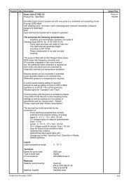
Station Delay<br />
This feature is commonly used by homeowners with cisterns or well<br />
water. The delay allows cisterns and wells adequate time to re-supply<br />
the reservoir.<br />
Note: Delays between stations can be programmed from 1 minute to 9 hours.<br />
TO PROGRAM STATION DELAY:<br />
1. Turn the rotary dial to •STATION DELAY [See Figure 22]<br />
2. To increase or decrease the time delay time between each station,<br />
press the + or – button.<br />
3. Press the ENTER button to save the time delay setting.<br />
4. Return the rotary dial to AUTO<br />
SET<br />
DELAY TIME<br />
0<br />
Figure 22: Display – Station Delay<br />
Section 7: Installation of Indoor Mount<br />
Sprinkler Timer<br />
3. Installing the Batteries<br />
4. Connecting the Power Supply<br />
5. Connecting Valve Wires to Sprinkler Timer<br />
Note: For installation of OUTDOOR models see Appendix A<br />
1. Selecting a Location<br />
Select a location with the following criteria:<br />
• Near an electrical outlet (Avoid using an outlet controlled by<br />
a switch)<br />
• An indoor, dry location, where operating temperatures are not<br />
below 32° or above 158° Fahrenheit (0 degrees or above 70<br />
degrees Celsius)<br />
• Avoid direct sunlight<br />
• Access to sprinkler wire (from valves)<br />
2. Mounting the Sprinkler Timer<br />
• Using the mounting template (included) mark the screw<br />
locations on the wall.<br />
• Insert a No. 8 screw (included) in the upper mark, leaving the<br />
screw head about 1/8th (3mm) out from the wall. (Use the<br />
expanding anchors in plaster or masonry if necessary.)<br />
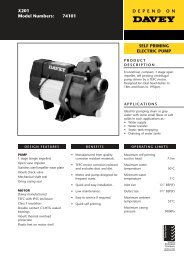
• Slip the keyhole slot in the back of the sprinkler timer over the<br />
extended screw. [See Figure 23]<br />
• Replace the battery cover<br />
Note: Batteries alone will not operate the valves in your sprinkling system.<br />
The 24-volt transformer must be plugged in and have power to operate<br />
your system normally.<br />
Keyhole<br />
Screw holes<br />
No. 8 Screw<br />
Wall<br />
Figure 23: Mounting the Sprinkler Timer<br />
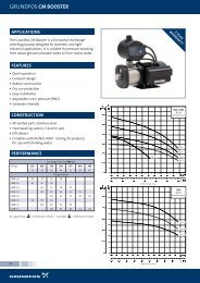
4. Connecting the Transformer<br />
• With the cover off, find the two terminal holes labeled<br />
“24VAC IN” [See Figure 25]<br />
• Insuring the transformer is not plugged in; insert one of two<br />
power leads (from the transformer) into each terminal.<br />
Note: It may be necessary to open the terminal to allow for wire insertion<br />
or removal. This is done by pressing upward on the tab located on top of<br />
the terminal.<br />
• Plug in the transformer.<br />
Warning: Do not link two or more sprinkler timers together with<br />
one transformer.<br />
24VAC-OUT SENSOR COMMON PUMP 1 2 3 4 5 6 24VAC-IN<br />
Figure 25: Connecting the Transformer<br />
Transformer<br />
ENGLISH<br />
Before installation please have the following items and tools.<br />
• 2 AA Batteries<br />
• Phillips Screwdriver<br />
• Wire Strippers<br />
Installing the sprinkler timer in 5 easy steps<br />
1. Selecting a Location<br />
2. Mounting the Sprinkler Timer<br />
• Screw a No. 8 screw through the two holes located behind the<br />
batteries in the battery compartment.<br />
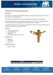
3. Install the Batteries<br />
Two AA alkaline batteries are required to retain the program in memory<br />
during power loss. Annual replacement is recommended.<br />
• Remove the battery cover by sliding it to the left. [See Figure 24]<br />
• Insert two AA alkaline batteries<br />
Figure 24: Battery Compartment<br />
Section 8: Wiring Valves, Sprinkler Timer,<br />
Pump Start and Master Valves<br />
1. Wiring the Electric Valves<br />
Note: If the distance between the sprinkler timer and valves is under 700'<br />
(210 m), use Orbit ® sprinkler wire or 20 gauge (AWG) plastic jacketed<br />
thermostat wire to connect the sprinkler timer to the valves. If the distance<br />
is over 700' (210 m), use 16 gauge (AWG) wire.<br />
14<br />
15