Manual de Instalación y Uso Instruction Manual - Fagor Electrónica
Manual de Instalación y Uso Instruction Manual - Fagor Electrónica
Manual de Instalación y Uso Instruction Manual - Fagor Electrónica

Create successful ePaper yourself
Turn your PDF publications into a flip-book with our unique Google optimized e-Paper software.
DETECTORES DE GAS MIXTO<br />
NATURAL GAS & CARBON MONOXIDE<br />
DUAL GAS ALARM<br />
<strong>Manual</strong> <strong>de</strong> <strong>Instalación</strong> y <strong>Uso</strong><br />
<strong>Instruction</strong> <strong>Manual</strong><br />
DGM 300 Series<br />
1
1. I N T R O D U C C I Ó N<br />
Este Detector <strong>de</strong> Gas Mixto está preparado para la <strong>de</strong>tección <strong>de</strong> Gas Natural y<br />
Monóxido <strong>de</strong> Carbono. No es operativo con Gases Licuados <strong>de</strong>l Petróleo (GLP).<br />
Ha sido diseñado para uso doméstico en un espacio ventilado. Está provisto <strong>de</strong><br />
señales <strong>de</strong> salida, permitiendo su uso como elemento autónomo, con una función<br />
simple <strong>de</strong> ejecución, o como parte <strong>de</strong> una Red <strong>de</strong> elementos Domóticos (sólo en<br />
los mo<strong>de</strong>los DGM 3XX-D).<br />
Este <strong>de</strong>tector está diseñado para advertir <strong>de</strong> una exposición severa al monóxido<br />
<strong>de</strong> carbono pero pue<strong>de</strong> no proteger a personas especialmente sensibles a la<br />
exposición constante por razones <strong>de</strong> edad, embarazo o salud. En caso <strong>de</strong> duda,<br />
consulte a su médico.<br />
Este Detector <strong>de</strong> Gas Natural y Monóxido <strong>de</strong> Carbono está pensado para su<br />
funcionamiento continuo y no <strong>de</strong>be utilizarse <strong>de</strong> forma intermitente. No es un<br />
sustituto <strong>de</strong> un <strong>de</strong>tector <strong>de</strong> humo, y no <strong>de</strong>be ser utilizado como un <strong>de</strong>tector portátil<br />
para fugas <strong>de</strong> productos <strong>de</strong> combustión. La correcta instalación y el a<strong>de</strong>cuado<br />
mantenimiento <strong>de</strong> los aparatos <strong>de</strong> combustión <strong>de</strong> gas y <strong>de</strong> sus conductos <strong>de</strong><br />
extracción <strong>de</strong> humos <strong>de</strong>be ser una prioridad <strong>de</strong> cara a mantener un elevado nivel<br />
seguridad en la vivienda.<br />
El <strong>de</strong>tector <strong>de</strong>be ser instalado por personal cualificado siguiendo las instrucciones<br />
suministradas. El manual <strong>de</strong> instrucciones <strong>de</strong>be ser contemplado como parte <strong>de</strong>l<br />
producto y <strong>de</strong>be ser guardado durante la vida <strong>de</strong>l mismo. Si el producto cambiara<br />
<strong>de</strong> propietario, el manual <strong>de</strong>bería traspasarse a su siguiente usuario. No manipule<br />
el interior <strong>de</strong> la caja ya que pue<strong>de</strong> causar un malfuncionamiento <strong>de</strong>l <strong>de</strong>tector o<br />
recibir una <strong>de</strong>scarga eléctrica.<br />
ES IMPORTANTE QUE LEA Y ENTIENDA ESTAS INSTRUCCIONES<br />
ANTES DE INSTALAR EL DETECTOR DE GAS MIXTO<br />
2
2 . D E S C R I P C I Ó N D E L P R O D U C T O<br />
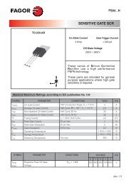
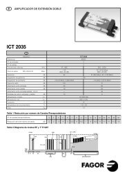
Figura 1. Vista General <strong>de</strong>l Detector <strong>de</strong> Gas Mixto.<br />
CO (led rojo):<br />
indicador luminoso<br />
<strong>de</strong> concentración<br />
peligrosa <strong>de</strong><br />
monóxido <strong>de</strong><br />
carbono.<br />
GAS (led rojo):<br />
indicador<br />
luminoso <strong>de</strong><br />
concentración<br />
peligrosa <strong>de</strong> gas<br />
natural.<br />
SENSOR<br />
POWER<br />
(led ver<strong>de</strong>):<br />
indicador<br />
luminoso <strong>de</strong><br />
correcto<br />
funcionamiento.<br />
ERROR<br />
(led amarillo):<br />
indicador<br />
luminoso <strong>de</strong> fallo<br />
<strong>de</strong> funcionamiento<br />
<strong>de</strong>l <strong>de</strong>tector.<br />
ZUMBADOR<br />
Botón TEST/RESET:<br />
• Función TEST:<br />
Chequea el funcionamiento<br />
<strong>de</strong>l <strong>de</strong>tector.<br />
• Función RESET:<br />
Permite silenciar el<br />
zumbador y/o restablecer<br />
la situación <strong>de</strong> reposo.<br />
3 . I N S T R U C C I O N E S D E I N S TA L A C I Ó N<br />
3.1. Dón<strong>de</strong> instalar el <strong>de</strong>tector<br />
El Detector <strong>de</strong> Gas <strong>de</strong>be <strong>de</strong> ser instalado en el interior <strong>de</strong> la vivienda. Para una<br />
correcta <strong>de</strong>tección <strong>de</strong> gas <strong>de</strong>be estar situado en una pared libre <strong>de</strong> obstáculos en<br />
el recinto don<strong>de</strong> existe un aparato <strong>de</strong> combustión <strong>de</strong> gas. En la mayoría <strong>de</strong> las<br />
instalaciones éste será una encimera <strong>de</strong> cocina a gas o una cal<strong>de</strong>ra <strong>de</strong> gas. Para<br />
el correcto funcionamiento <strong>de</strong>l Detector <strong>de</strong> Gas <strong>de</strong>be estar situado en posición<br />
vertical.<br />
3
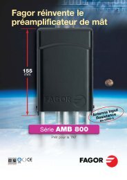
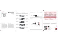
El gas natural (metano en su mayor parte) es menos pesado que el aire, por lo<br />
tanto el <strong>de</strong>tector conviene que esté situado por encima <strong>de</strong> la apertura más elevada<br />
<strong>de</strong>l recinto, normalmente no a más <strong>de</strong> 30cm <strong>de</strong>l techo y entre 1 a 3 metros <strong>de</strong>l<br />
aparato <strong>de</strong> combustión (Ver Figura 2). Esta ubicación <strong>de</strong>be dar buena protección<br />
ante el monóxido <strong>de</strong> carbono flotante (originada <strong>de</strong>s<strong>de</strong> una fuente caliente) en la<br />
misma habitación. Sin embargo, si no hay ningún aparato <strong>de</strong> combustión <strong>de</strong> gas<br />
en la misma habitación que el <strong>de</strong>tector, <strong>de</strong>be instalarse a unos 2 m <strong>de</strong>l suelo para<br />
una protección óptima.<br />
Figura 2.<br />
Ubicación <strong>de</strong>l Detector <strong>de</strong> Gas Mixto.<br />
3.2. Dón<strong>de</strong> no instalar el <strong>de</strong>tector<br />
· Fuera <strong>de</strong>l edificio.<br />
· En un recinto cerrado, p.e. <strong>de</strong>ntro <strong>de</strong> un armario o <strong>de</strong>trás <strong>de</strong> una cortina.<br />
· Directamente encima <strong>de</strong> un frega<strong>de</strong>ro o una cocina.<br />
· Cerca <strong>de</strong> una puerta, ventana o un extractor.<br />
· En un área don<strong>de</strong> la Tª pue<strong>de</strong> bajar por <strong>de</strong>bajo <strong>de</strong> –5ºC o subir por encima <strong>de</strong> +40ºC.<br />
· Don<strong>de</strong> la suciedad o el polvo puedan bloquear el sensor o parar el funcionamiento.<br />
· En areas húmedas.<br />
· Don<strong>de</strong> sea susceptible <strong>de</strong> ser golpeado o dañado.<br />
3.3. <strong>Instalación</strong> y Sujeción <strong>de</strong>l <strong>de</strong>tector<br />
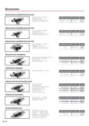
El Detector <strong>de</strong> Gas pue<strong>de</strong> ser sujetado a la superficie <strong>de</strong> la pared o a una caja<br />
eléctrica universal <strong>de</strong> 60 mm. El <strong>de</strong>tector está compuesto por una caja y un soporte<br />
<strong>de</strong> sujeción a la pared. El soporte se libera <strong>de</strong> la caja con la ayuda <strong>de</strong> un <strong>de</strong>stornillador<br />
ejerciendo presión sobre la pestaña inferior hacia abajo hasta que la caja queda<br />
libre. La caja pue<strong>de</strong> girar con libertad para acce<strong>de</strong>r a los terminales <strong>de</strong> conexión.<br />
(Ver Figura 3).<br />
4
Figura 3.<br />
Liberación <strong>de</strong> la caja sobre la base.<br />
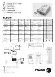
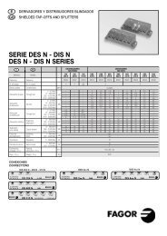
El <strong>de</strong>tector <strong>de</strong>be ser conectado directamente y <strong>de</strong> forma permanente a la red<br />
eléctrica <strong>de</strong> 230V conectando el cable <strong>de</strong> red en el borne <strong>de</strong> conexión situado en<br />
el soporte, en los 2 polos <strong>de</strong>l lado izquierdo <strong>de</strong>l conector marcados como “AC-<br />
INPUT 230V” (Ver Figura 4), <strong>de</strong>jando los 2 restantes marcados como ALARM<br />
OUTPUT” para la conexión <strong>de</strong> una válvula <strong>de</strong> corte a 230V.<br />
En caso <strong>de</strong> utilizar una caja universal empotrada en la pared siga los siguientes pasos:<br />
1. Coloque el soporte sobre la caja <strong>de</strong> empotrar con la pestaña en la parte inferior.<br />
2. Introduzca el cable <strong>de</strong> red <strong>de</strong> la caja empotrada a través <strong>de</strong> la ventana central<br />
por la parte trasera <strong>de</strong>l soporte.<br />
3. Conecte el cable <strong>de</strong> red al borne <strong>de</strong> conexión. Para facilitar la operación, el borne<br />
pue<strong>de</strong> extraerse <strong>de</strong>l soporte liberando las pestañas laterales con la ayuda <strong>de</strong><br />
un <strong>de</strong>stornillador.<br />
4. Atornille el soporte a la caja <strong>de</strong> empotrar mediante 2 tornillos.<br />
Si el <strong>de</strong>tector va instalado sobre la pared siga los siguientes pasos:<br />
1. Conecte el cable <strong>de</strong> alimentación en el borne <strong>de</strong> conexión. (Ver Figura 4)<br />
2. Coloque el soporte en una zona lisa <strong>de</strong> la pared con la pestaña en la parte<br />
inferior. Asegure que tiene suficiente longitud <strong>de</strong> cable <strong>de</strong>s<strong>de</strong> el soporte a la<br />
base <strong>de</strong> enchufe antes <strong>de</strong> fijarlo a la pared.<br />
3. Una vez seleccionada su ubicación realice 3 agujeros <strong>de</strong> Ø 5mm en las posiciones<br />
<strong>de</strong> los tornillos.<br />
4. Introduzca los tacos en los agujeros y atornille el soporte a la pared utilizando<br />
los tacos y tornillos <strong>de</strong> la bolsa accesorio.<br />
5<br />
Figura 4.<br />
Conexiones <strong>de</strong> cableado eléctrico.
Una vez que el soporte está sujeto a la pared<br />
coloque la caja <strong>de</strong>l <strong>de</strong>tector en la misma posición<br />
<strong>de</strong> origen. Primeramente inserte los ganchos<br />
superiores <strong>de</strong> la caja sobre el soporte y gire<br />
suavemente hacia la posición vertical hasta que<br />
la pestaña inferior que<strong>de</strong> encajada en el soporte,<br />
teniendo cuidado <strong>de</strong> la correcta conexión <strong>de</strong> los<br />
contactos traseros <strong>de</strong> la caja en el borne <strong>de</strong><br />
conexión (Ver Figura 5).<br />
Figura 5.<br />
Colocación <strong>de</strong> la caja sobre el soporte.<br />
4. PUESTA EN MARCHA Y FUNCIONAMIENTO<br />
Des<strong>de</strong> el momento en el que el Detector <strong>de</strong> Gas se conecta a la red eléctrica <strong>de</strong><br />
230V el indicador luminoso ver<strong>de</strong> (marcado como POWER) comienza a parpa<strong>de</strong>ar<br />
durante un periodo <strong>de</strong> calentamiento <strong>de</strong> unos 2 minutos. Una vez transcurridos,<br />
el indicador POWER permanece iluminado indicando su correcto funcionamiento.<br />
Durante el periodo <strong>de</strong> calentamiento el Detector no respon<strong>de</strong> al gas como<br />
consecuencia <strong>de</strong> la estabilización <strong>de</strong>l sensor.<br />
4.1. Situación <strong>de</strong> alarma<br />
Cuando la concentración <strong>de</strong> gas natural o monóxido <strong>de</strong> carbono alcanza el nivel<br />
<strong>de</strong> alarma, el Detector avisa mediante la iluminación <strong>de</strong> los indicadores rojos<br />
(marcados como GAS para Gas Natural y como CO para Monóxido <strong>de</strong> Carbono,<br />
Ver Figura 1) y una llamativa alarma sonora. La salida <strong>de</strong> relé será activada cerrando<br />
el contacto libre <strong>de</strong> tensión para señalización externa o para la activación <strong>de</strong> una<br />
válvula <strong>de</strong> corte.<br />
Es posible que se <strong>de</strong>tecte el olor característico <strong>de</strong>l gas natural a niveles inferiores<br />
a los niveles <strong>de</strong> alarma calibrados en el <strong>de</strong>tector. Esto no <strong>de</strong>be interpretarse como<br />
fallo <strong>de</strong>l <strong>de</strong>tector. En el caso <strong>de</strong>l CO, el indicador rojo pue<strong>de</strong> empezar a parpa<strong>de</strong>ar<br />
antes <strong>de</strong> alcanzar el tiempo <strong>de</strong> alarma (sin que se active la alarma audible) como<br />
aviso <strong>de</strong> que niveles pequeños <strong>de</strong> gas están presentes.<br />
6
EN CASO DE ALARMA, LAS SIGUIENTES ACCIONES DEBEN SER TOMADAS:<br />
- Mantenga la calma. Pulse TEST/RESET si el indicador <strong>de</strong> CO está iluminado.<br />
- Apague cualquier llama. No fume ni encienda ni apague ningún interruptor<br />
eléctrico.<br />
- Abra las puertas y ventanas para evacuar el gas.<br />
- Cierre la llave suministro <strong>de</strong> gas y todos los electrodomésticos <strong>de</strong><br />
combustión. No utilice ningún electrodoméstico hasta que haya sido<br />
inspeccionado por un experto.<br />
- Si alguien sufre <strong>de</strong> los posibles efectos <strong>de</strong> envenenamiento por CO (p.e.<br />
dolor <strong>de</strong> cabeza, mareos, nausea o vómitos) consiga ayuda médica y avise<br />
<strong>de</strong> la sospecha <strong>de</strong> envenenamiento por monóxido <strong>de</strong> carbono.<br />
- En caso <strong>de</strong> que la alarma persista, y la causa <strong>de</strong> la fuga no sea evi<strong>de</strong>nte o<br />
no pueda ser reparada, evacue el local o la vivienda INMEDIATAMENTE<br />
<strong>de</strong>jando las puertas y ventanas abiertas. Notifique el hecho al distribuidor<br />
o a un servicio <strong>de</strong> emergencia <strong>de</strong> gas.<br />
4.2. Desactivación <strong>de</strong> la alarma y restablecimiento <strong>de</strong><br />
la situación normal<br />
Una vez que el gas ha <strong>de</strong>saparecido, el Detector <strong>de</strong> Gas <strong>de</strong>tiene la alarma Sonora<br />
y los pilotos <strong>de</strong> alarma pasan a un estado <strong>de</strong> parpa<strong>de</strong>o en espera <strong>de</strong>l reconocimiento<br />
<strong>de</strong> la alarma por parte <strong>de</strong>l usuario. En este estado se mantiene activa la salida <strong>de</strong><br />
alarma. Para restablecer la situación <strong>de</strong> reposo pulse durante varios segundos el<br />
pulsador TEST/RESET hasta escuchar un pitido. En este momento el piloto rojo<br />
<strong>de</strong> alarma queda apagado y el relé <strong>de</strong> activación <strong>de</strong> la alarma se <strong>de</strong>sactiva. Si la<br />
salida <strong>de</strong> alarma está conectada a una electroválvula <strong>de</strong> rearme manual ésta <strong>de</strong>be<br />
abrirse manualmente.<br />
Atención: Antes <strong>de</strong> <strong>de</strong>sactivar la alarma y rearmar el sistema <strong>de</strong>berá<br />
eliminar la causa <strong>de</strong>l problema, o bien cerrar el paso general <strong>de</strong> gas<br />
mediante el cierre manual <strong>de</strong> la llave <strong>de</strong> paso, ya que en el momento que<br />
se <strong>de</strong>sactiva la alarma la electroválvula se abre y vuelve a haber gas en<br />
la vivienda.<br />
La función <strong>de</strong> RESET o puesta en reposo no será operativa mientras la concentración<br />
<strong>de</strong> gas supere el nivel <strong>de</strong> alarma.<br />
7
4.3. Función Autotest / Silenciamiento <strong>de</strong> la Alarma<br />
Mediante la pulsación <strong>de</strong> TEST/RESET durante el funcionamiento normal (<strong>de</strong>spués<br />
<strong>de</strong>l precalentamiento) se inicia el autotest. Los indicadores se iluminan<br />
secuencialmente y la alarma sonora es activada durante 1 segundo. Todos los<br />
indicadores permanecen encendidos hasta que se pulse una segunda vez, tras lo<br />
cual el piloto POWER permanece iluminado indicando el funcionamiento normal.<br />
Si se pulsa una segunda vez manteniendo pulsado TEST/RESET durante 10<br />
segundos se testea la activación <strong>de</strong>l relé. Los indicadores <strong>de</strong> alarma permanecen<br />
encendidos y el relé es activado. Una vez comprobado el funcionamiento <strong>de</strong>l test<br />
<strong>de</strong> alarma, el sistema pue<strong>de</strong> ponerse en reposo pulsando brevemente el pulsador<br />
TEST/RESET.<br />
Es recomendable realizar este autotest una vez a la semana para confirmar su<br />
correcto funcionamiento. Si la respuesta <strong>de</strong>l Detector es diferente <strong>de</strong> la <strong>de</strong>scrita<br />
anteriormente, no funciona correctamente. REEMPLACELO INMEDIATAMENTE.<br />
Pulsando el botón TEST/RESET durante una alarma <strong>de</strong> CO silencia el zumbador<br />
durante aproximadamente 6 minutos. El indicador rojo <strong>de</strong> CO permanece iluminado.<br />
Si el nivel alto <strong>de</strong> CO persiste, el zumbador se activará automáticamente y no<br />
podrá ser silenciado hasta que el CO haya <strong>de</strong>saparecido hasta niveles seguros.<br />
Esta función <strong>de</strong> silenciamiento no funciona durante alarmas <strong>de</strong> gas natural, ni<br />
cuando los niveles <strong>de</strong> CO sean altos, ya que esta situación pue<strong>de</strong> ser particularmente<br />
peligrosa.<br />
4.4. Sensor<br />
Un fiable y preciso sensor semiconductor monitoriza constantemente el nivel <strong>de</strong><br />
Gas Natural y Monóxido <strong>de</strong> Carbono en el aire. Este sistema <strong>de</strong> sensor informa a<br />
un microprocesador continuamente y con precisión <strong>de</strong> la presencia <strong>de</strong> tan sólo<br />
pocas partes por millón (ppm) <strong>de</strong> Gas Natural o Monóxido <strong>de</strong> Carbono. El<br />
microprocesador a<strong>de</strong>más <strong>de</strong> medir el nivel <strong>de</strong> gas en el aire, testea el correcto<br />
funcionamiento <strong>de</strong>l sensor, circuitos electrónicos y fuente <strong>de</strong> alimentación.<br />
Cuando el microprocesador diagnostica un problema durante su regular testeo, el<br />
indicador amarillo (marcado como ERROR) se ilumina y el <strong>de</strong>tector interrumpe su<br />
funcionamiento. Si esto ocurre su <strong>de</strong>tector no le está ofreciendo protección<br />
REEMPLACELO INMEDIATAMENTE.<br />
8
4.5. Mantenimiento<br />
Para limpiar la caja utilice un paño húmedo. No utilice productos <strong>de</strong> limpieza, lejía<br />
o ceras. Evite utilizar los siguientes productos cerca <strong>de</strong>l Detector <strong>de</strong> Gas. Pue<strong>de</strong>n<br />
afectar a la fiabilidad y estabilidad a corto y largo plazo <strong>de</strong>l sensor:<br />
· Sprays aerosoles.<br />
· Alcoholes<br />
· Agentes limpiadores y disolventes.<br />
· Gas proveniente <strong>de</strong> encen<strong>de</strong>dores <strong>de</strong> tabaco.<br />
· Cigarrillos y humo.<br />
4.6. Mo<strong>de</strong>los Domóticos DGM 3XX-D<br />
Los mo<strong>de</strong>los DGM 3XX-D son una versión domótica que permite al Detector <strong>de</strong><br />
gas Mixto comunicarse con otros elementos <strong>de</strong> un sistema en red. Cuando el<br />
Detector entra en estado <strong>de</strong> alarma un mensaje <strong>de</strong> ALARMA es enviado a través<br />
<strong>de</strong> la red Eléctrica a otro nodos remotos <strong>de</strong>l sistema domótico, y tras la <strong>de</strong>sactivación<br />
<strong>de</strong> la alarma, al actuar sobre el pulsador TEST/RESET para el rearme <strong>de</strong>l sistema,<br />
otro mensaje <strong>de</strong> FIN <strong>de</strong> ALARMA es enviado <strong>de</strong>l mismo modo. Estos mensajes<br />
están basados en un estándar <strong>de</strong> comunicación, especialmente <strong>de</strong>rivado para re<strong>de</strong>s<br />
domóticas, como el siguiente:<br />
· Modulación <strong>de</strong> Comunicación: FSK 132.45 KHz (Máx. 120 dBuV)<br />
· Protocolo <strong>de</strong> comunicación: BDF V4.0 (Bus Domótico <strong>Fagor</strong>)<br />
4.6.1. Configuración <strong>de</strong>l Sistema Domótico<br />
El Detector <strong>de</strong> Gas Domótico dispone <strong>de</strong> una lista <strong>de</strong> actuaciones en su memoria<br />
y permite enviar mensajes <strong>de</strong> alarma hasta un máximo <strong>de</strong> 8 dispositivos <strong>de</strong><br />
actuación (servidores). Los actuadores <strong>de</strong> corte <strong>de</strong> gas instalados en la misma<br />
instalación que el Detector son <strong>de</strong>tectados automáticamente por el Detector y<br />
guardados en su lista <strong>de</strong> actuación como un elemento servidor. A<strong>de</strong>más po<strong>de</strong>mos<br />
asociar otros elementos <strong>de</strong> actuación domóticos como luces, sirenas o extractores<br />
<strong>de</strong> aire hasta completar la lista <strong>de</strong> 8 servidores que pue<strong>de</strong> controlar cada Detector.<br />
9
Cada vez que el <strong>de</strong>tector active el proceso <strong>de</strong> alarmas enviará la or<strong>de</strong>n <strong>de</strong> cierre a<br />
los actuadores <strong>de</strong> corte <strong>de</strong> gas y <strong>de</strong> encendido o apagado a cada uno <strong>de</strong> los restantes<br />
actuadores según la función configurada. Una vez que haya <strong>de</strong>saparecido la alarma<br />
y el usuario haya actuado sobre el pulsador <strong>de</strong> reset, el Detector enviará la or<strong>de</strong>n<br />
<strong>de</strong> apertura <strong>de</strong> los actuadores <strong>de</strong> corte <strong>de</strong> gas. Sin embargo basta con que se<br />
cumpla una <strong>de</strong> las 2 condiciones anteriores, la <strong>de</strong>saparición <strong>de</strong> la alarma o la<br />
actuación <strong>de</strong>l pulsador <strong>de</strong> Reset, para que el <strong>de</strong>tector envíe la or<strong>de</strong>n inversa a la<br />
<strong>de</strong> alarma al resto <strong>de</strong> los actuadores.<br />
4.6.2. Enrolamientos Domóticos<br />
En modo normal pulsando el pulsador TEST/RESET durante 2 segundos el Detector<br />
entra en modo <strong>de</strong> configuración domótica. Los indicadores luminosos POWER y<br />
ERROR permanecen iluminados. Pulsando una segunda vez durante 2 segundos<br />
comienza el proceso <strong>de</strong> enrolamiento. El piloto POWER comienza a parpa<strong>de</strong>ar<br />
durante 2 minutos (1Hz) a la espera <strong>de</strong> la presentación <strong>de</strong> los actuadores. Durante<br />
este tiempo todos los actuadores <strong>de</strong>ben ser introducidos en proceso <strong>de</strong> enrolamiento<br />
<strong>de</strong>l mismo modo. Cada vez que un nuevo actuador es enrolado el <strong>de</strong>tector inicializará<br />
el contador <strong>de</strong> 2 minutos a la espera <strong>de</strong> la presentación <strong>de</strong> más actuadores.<br />
Cuando termina el enrolamiento, el <strong>de</strong>tector pasa a modo <strong>de</strong> funcionamiento<br />
normal pulsando el pulsador brevemente. El piloto ERROR <strong>de</strong> apaga y el piloto<br />
POWER permanece iluminado.<br />
Este proceso <strong>de</strong>be repetirse cada vez que un nuevo actuador es añadido al sistema.<br />
4.6.3. Cómo borrar la lista <strong>de</strong> enrolamientos Domóticos<br />
En modo normal pulsando el pulsador TEST/RESET durante 2 segundos el Detector<br />
entra en modo configuración domótica en el cual los indicadores luminosos POWER<br />
y ERROR permanecen iluminados. Pulsando una segunda vez y manteniendo<br />
pulsado TEST/RESET durante 10 segundos la lista <strong>de</strong> enrolamientos es borrada.<br />
El piloto POWER comenzará a parpa<strong>de</strong>ar durante varios segundos y pasa<br />
automáticamente modo <strong>de</strong> funcionamiento normal.<br />
10
5 . E S P E C I F I C A C I O N E S<br />
5.1. Características principales<br />
Los mo<strong>de</strong>los <strong>de</strong>l Detector <strong>de</strong> Gas Mixto <strong>de</strong> la serie DGM 300 tienes las mismas<br />
especificaciones <strong>de</strong> funcionamiento:<br />
· Rango <strong>de</strong> Tensión <strong>de</strong> Alimentación: 185 a 264 Vac<br />
· Frecuencia <strong>de</strong> Alimentación: 50-60 Hz<br />
· Máxima Potencia Consumida: 1,5W<br />
· Salida <strong>de</strong> alarma: Contacto libre <strong>de</strong> tensión<br />
(Normalmente abierto) (Max.277 V AC/ 3A)<br />
· Rango <strong>de</strong> Temperatura <strong>de</strong> funcionamiento: -5 a 40 ºC<br />
· Rango <strong>de</strong> Humedad <strong>de</strong> funcionamiento: 30 a 90 % RH<br />
· Nivel sonoro: 85 dB(A) a 3 m.<br />
· Dimensiones : 145mm(Al)x100mm(An)x55mm(Pr)<br />
· Peso: 200 gr.<br />
Cabe remarcar que la válvula <strong>de</strong> corte <strong>de</strong>be ser <strong>de</strong>l tipo normalmente abierta<br />
(cerrada cuando el alimentada eléctricamente) y que es esencial su reapertura<br />
manual, para cumplir con la directiva <strong>de</strong> aparatos <strong>de</strong> gas (90/396/EEC) y regulaciones<br />
<strong>de</strong> aparatos <strong>de</strong> gas (Seguridad) <strong>de</strong> 1992.<br />
11
5.2. Funcionamiento <strong>de</strong>l Detector <strong>de</strong> Gas<br />
El funcionamiento <strong>de</strong>l <strong>de</strong>tector está diseñado para cumplir las normas UNE EN<br />
50291:2001 para monóxido <strong>de</strong> carbono y UNE EN 50194:2000 para Gas Natural<br />
usando los criterios siguientes:<br />
· Alarma Gas Natural: 9% LIE (Límite Inferior <strong>de</strong> Explosividad) en 20 segs.<br />
· Alarma Monóxido <strong>de</strong> Carbono:<br />
Nivel CO Tiempo para Aviso Tiempo para Alarma<br />
(ppm)<br />
(minutos)<br />
(minutos)<br />
30<br />
50<br />
100<br />
300<br />
No Aviso<br />
15< 30<br />
2 < 10<br />
Ninguno<br />
No alarma<br />
60 < 90<br />
10 < 40<br />
< 3<br />
Este Detector <strong>de</strong> Gas Mixto está calibrado en fábrica y no necesita recalibración.<br />
Sin embargo, para optima fiabilidad, <strong>de</strong>be ser remplazado no más tar<strong>de</strong> <strong>de</strong><br />
transcurridos 5 años <strong>de</strong>s<strong>de</strong> <strong>de</strong> la fecha <strong>de</strong> instalación, como <strong>de</strong>be ser indicado en<br />
la etiqueta incluida en la caja.<br />
12
DETECTORES DE GAS MIXTO<br />
NATURAL GAS & CARBON MONOXIDE<br />
DUAL GAS ALARM<br />
<strong>Manual</strong> <strong>de</strong> <strong>Instalación</strong> y <strong>Uso</strong><br />
<strong>Instruction</strong> <strong>Manual</strong><br />
DGM 300 Series<br />
1
1. I N T R O D U C T I O N<br />
The Dual Gas Alarm is for use only with Natural Gas and Carbon Monoxi<strong>de</strong>. It<br />
will not operate with Liquid Petroleum Gas (LPG). It is <strong>de</strong>signed to operate insi<strong>de</strong><br />
the house in a location with free access to air in the room. Output signals are<br />
provi<strong>de</strong>d, allowing it to be used as a stand-alone unit, or with a simple executive<br />
function, or as part of a network of domestic appliances (mo<strong>de</strong>ls DGM 3XX-D<br />
only).<br />
This Gas Alarm is inten<strong>de</strong>d to warn of acute exposure to carbon monoxi<strong>de</strong>, but<br />
may not protect people who are at special risk from chronic exposure by reason<br />
of age, pregnancy or medical condition. If in doubt, consult your medical<br />
practitioner.<br />
This natural gas and carbon monoxi<strong>de</strong> Alarm is inten<strong>de</strong>d for continuous energisation,<br />
and should not be used on an intermittent basis. It is not a substitute for a smoke<br />
alarm, and must not be used as a portable <strong>de</strong>tector for the spillage of combustion<br />
products. Proper installation and servicing of gas burning appliances and their<br />
flues is still a priority for security in the home.<br />
The <strong>de</strong>tector should be installed by a competent person, using the instructions<br />
provi<strong>de</strong>d. The instruction manual should be regar<strong>de</strong>d as part of the product, and<br />
be retained for the life of the product. If the product changes ownership, then the<br />
manual should be passed to any subsequent user. Do not tamper with the insi<strong>de</strong><br />
of the casing, since this may stop the <strong>de</strong>tector working or cause an electric shock.<br />
READ AND UNDERSTAND THESE INSTRUCTIONS<br />
BEFORE INSTALLING THE DETECTOR<br />
2
2 . P R O D U C T D E S C R I P T I O N<br />
Figure 1: General View of the Dual Gas Alarm<br />
CO (red led):<br />
light indicating a<br />
dangerous<br />
concentration of<br />
carbon monoxi<strong>de</strong>.<br />
GAS (red led):<br />
light indicating a<br />
dangerous<br />
concentration of<br />
natural gas.<br />
SENSOR<br />
POWER<br />
(green led):<br />
light indicating<br />
correct operation.<br />
ERROR<br />
(yellow led):<br />
light indicating an<br />
error in the<br />
operation of the<br />
<strong>de</strong>tector.<br />
BUZZER<br />
3. I N S T A L L A T I O N I N S T R U C T I O N S<br />
3.1. Where to install the <strong>de</strong>tector<br />
TEST/RESET button:<br />
• TEST function: Checks<br />
that the <strong>de</strong>tector is working<br />
properly.<br />
• RESET function: Silences<br />
the buzzer and and/or resets<br />
the <strong>de</strong>vice.<br />
The Dual Gas Alarm must be installed insi<strong>de</strong> the house. For proper protection of<br />
the occupants, it should be placed on a suitable flat wall in a room containing a<br />
gas-burning appliance. In most cases, this will be a kitchen with a gas cooker. For<br />
proper operation of the <strong>de</strong>tector, it has to be installed in a vertical position.<br />
3
The major component of natural gas is methane, which is much lighter than air,<br />
so the <strong>de</strong>tector should be placed above the top of the highest opening in the room,<br />
usually not more than 30 cm (1’) from the ceiling. Horizontally, it should be<br />
positioned between 1 m (3’) and 3 m (10’) from the gas-burning appliance (see<br />
Figure 2). This location will also give good protection from buoyant carbon monoxi<strong>de</strong><br />
(i.e. arising from a hot source) within the same room. However, if there is no gasburning<br />
appliance in the same room as the <strong>de</strong>tector, it should be located about 2<br />
m (6’) above the floor, for optimum protection.<br />
Figure 2.<br />
Position of the Mixed Gas Detector.<br />
3.2. Where not to install the <strong>de</strong>tector<br />
· Outsi<strong>de</strong> the building<br />
· In an enclosed space (e.g. insi<strong>de</strong> a cupboard or behind a curtain)<br />
· Directly above a sink or a cooker<br />
· Next to a door, or a window, or an extractor fan<br />
· In an area where the temperature can drop below –5ºC or rise above +40ºC<br />
· Where dirt and dust can block the sensor and stop it working<br />
· Damp or humid areas<br />
· Where it is likely to be knocked or damaged<br />
3.3. Installation and fixing<br />
The <strong>de</strong>tector can be fixed directly to a wall surface, or screwed to a standard<br />
universal 60 mm electrical distribution pattress, if preferred. The <strong>de</strong>tector comprises<br />
a main casing, with a base for wall fixing. The base is released from the casing<br />
by pressing the bottom catch downwards until the casing comes loose. The casing<br />
can then be swung clear to expose the electrical terminals (see Figure 3).<br />
4
Figure 3.<br />
Releasing the Main Casing from the Base<br />
The <strong>de</strong>tector should be wired directly and permanently to the 220-240V mains<br />
supply. The electrical supply cable must be connected to the two left-hand screws<br />
of the terminal block in the base marked “AC-INPUT 230V” (see Figure 4) leaving<br />
the two right-hand screws marked “ALARM OUTPUT” for connection to a mainsoperated<br />
shut-off valve with manual reset, if <strong>de</strong>sired. Note that the installation<br />
of any such valve must comply with the requirements of BS EN 1775 for gas<br />
pipework in buildings.<br />
Locate the base on a smooth part of the wall with the catch downwards. Only use<br />
approved mains cable and plug meeting the national wiring co<strong>de</strong>s of the country<br />
of use. Ensure that there is sufficient length of cable from the base to the electrical<br />
outlet before attaching it to the wall, and then screw the base to the wall using<br />
the fixings provi<strong>de</strong>d. The <strong>de</strong>tector should be wired directly or plugged permanently<br />
into the mains supply via an un-switched, fused outlet to BS 5733.<br />
Figure 4.<br />
Electrical wiring connections.<br />
Figure 5.<br />
Replacing the<br />
Main Casing into<br />
the Base<br />
5<br />
Once the base is secured to<br />
the wall and connected to the<br />
mains, install the <strong>de</strong>tector<br />
main casing back in its original<br />
position. Insert the upper clips<br />
of the casing into the base,<br />
then swing it down vertically<br />
until the base catch clicks,<br />
taking care that the electrical<br />
connector pins enter into the<br />
terminal block correctly and<br />
smoothly (see Figure 5).
4 . O P E R A T I O N<br />
When the <strong>de</strong>tector is connected to the mains supply the green indicator light<br />
(marked POWER) starts blinking during a warm-up period of about 2 minutes.<br />
After that, it will remain illuminated as long as mains power is present. If the<br />
power supply is interrupted for any reason, the same warm-up procedure will<br />
apply when the power is re-established. Note that the <strong>de</strong>tector will not respond<br />
to gases during warm-up, as the sensor is stabilising.<br />
4.1. Alarm condition<br />
When natural gas or carbon monoxi<strong>de</strong> concentrations reach certain levels, the<br />
<strong>de</strong>tector will warn of the possible hazard, by illuminating the appropriate red alarm<br />
indicator lights (marked GAS and CO, see Figure 1) and the buzzer will make a<br />
loud bleeping noise. A relay output is also switched on closing a voltage free<br />
contact output for external signalling.<br />
It is sometimes possible to smell the characteristic odour of piped natural gas,<br />
at levels below that at which the <strong>de</strong>tector has been set to alarm. This should not<br />
be taken as a failure of the <strong>de</strong>tector. In the case of carbon monoxi<strong>de</strong> <strong>de</strong>tection,<br />
the red CO indicator may start blinking before the alarm time is reached (but<br />
without the audible alarm) as a warning that low levels of the gas are present.<br />
IN THE EVENT OF AN ALARM, THE FOLLOWING ACTIONS MUST BE TAKEN:<br />
- Keep calm. Press the Test/Hush button if the CO indicator light is<br />
illuminated.<br />
- Extinguish all naked flames. Do not smoke or turn electrical switches on<br />
or off.<br />
- Open doors and windows to get rid of the gas.<br />
- Turn off the gas supply at the meter and all gas appliances. Do not use<br />
the appliance again, until it has been checked by a CORGI registered<br />
installer.<br />
- Get medical help immediately for anyone suffering the possible effects<br />
of carbon monoxi<strong>de</strong> poisoning (e.g. headache, dizziness, nausea or<br />
vomiting) and advise that carbon monoxi<strong>de</strong> poisoning is suspected.<br />
- If the alarm continues to operate, and the source of the gas is not apparent,<br />
or cannot be corrected, evacuate the premises immediately, leaving the<br />
doors and windows open. Notify the Gas Emergency Service (telephone:<br />
0800 111 999) and do not re-enter the premises whilst the alarm continues<br />
to operate.<br />
6
4.2. Alarm <strong>de</strong>activation and normal condition reestablishment<br />
Once the gas has disappeared, the Detector stops sounding the audible alarm and<br />
the red alarm light will keep blinking until the user acknowledges the alarm. The<br />
alarm output will continue to be shut-off.<br />
To normal condition re-establishment, press the TEST/RESET button for a few<br />
seconds until you hear a beep. The red light indicators turn off and the alarm<br />
output relay and shutoff valve activation will be <strong>de</strong>activated. Note that the valve<br />
itself will need to be reset manually.<br />
Warning: before <strong>de</strong>activating the alarm and resetting the system you<br />
should eliminate the cause of the problem, or manually close the gas<br />
supply at the meter, as when the alarm is <strong>de</strong>activated the shut-off valve<br />
could be opened and the gas supply restored.<br />
The RESET function will not work while the concentration of gas exceeds the<br />
alarm level.<br />
4.3. Test and Hush Function<br />
Pressing the Test/Reset button briefly during normal operation (i.e. after warm<br />
up) initiates an alarm self-test. All indicator lights and the audible alarm are<br />
activated sequentially. The indicator lights then remain illuminated until the button<br />
is pressed briefly again, after which the green POWER light will remain illuminated,<br />
indicating normal operation. This test is recommen<strong>de</strong>d about once per week, to<br />
confirm that the <strong>de</strong>tector is functioning properly. If the response is different from<br />
that <strong>de</strong>scribed above, it is not functioning properly and must be replaced immediately.<br />
Activation of the relay output can be checked by initiating the alarm self-test as<br />
above, but then pressing and holding down the Test/Reset button for about ten<br />
seconds. Briefly pressing the button again afterwards will restore normal operation.<br />
7
Pressing the Test/Reset button for a few seconds during a CO alarm silences the<br />
buzzer for approximately 6 minutes. The red CO indicator light remains illuminated.<br />
If high carbon monoxi<strong>de</strong> levels persist, the buzzer automatically reactivates and<br />
cannot then be silenced, until the carbon monoxi<strong>de</strong> has reduced to safe levels<br />
again.<br />
The hush function will not work during natural gas alarms, nor when high carbon<br />
monoxi<strong>de</strong> levels are present, because these situations can be particularly hazardous.<br />
4.4. Sensor<br />
A reliable and accurate semiconductor sensor monitors the levels of natural gas<br />
and carbon monoxi<strong>de</strong> in the surrounding air. This sensor system continuously and<br />
accurately keeps a microcomputer informed of the presence of just a few parts<br />
per million (ppm) of natural gas or carbon monoxi<strong>de</strong>. The microcomputer, in<br />
addition to measuring the level of both gases in the air, also regularly tests to<br />
ensure that the sensor, internal circuits and power source are all functioning<br />
properly.<br />
If the microcomputer diagnoses a problem during its regular testing, the yellow<br />
indicator light (marked ERROR) is illuminated, and the <strong>de</strong>tector stops working.<br />
If this happens, the <strong>de</strong>tector is not providing protection, and must be replaced<br />
immediately.<br />
4.5. Maintenance<br />
To clean the casing, occasionally wipe it with a damp cloth. Do not use cleaning<br />
agents, bleach or polish. Avoid using the following near the gas <strong>de</strong>tector, since<br />
they might lead to false indications and affect the <strong>de</strong>tector reliability in the short<br />
or long term:<br />
· Aerosol sprays<br />
· Alcohol used in cooking<br />
· Tobacco smoke<br />
· Strong household cleaning agents, polishes or solvents<br />
· Gas from a cigarette lighter<br />
8
4.6. Home System Mo<strong>de</strong>ls DGM 3XX-D<br />
The DGM 3XX-D mo<strong>de</strong>ls enable the Dual Gas Alarm to communicate with other<br />
parts of a networked system. An ALARM message is sent via the power line to<br />
a remote system when the unit enters the alarm state, and an ALARM-END<br />
message is sent via the power line when the unit clears again. These messages<br />
are based on a standard communication method, specially <strong>de</strong>rived for domestic<br />
networking, as below:<br />
· Communication Modulation: FSK 132.45 KHz (Max 120 dBuV)<br />
· Communication Protocol: <strong>Fagor</strong> BDF (<strong>Fagor</strong> Domotic Bus) V4.0<br />
Correct operation of the communication messages can be checked in the same<br />
way as testing the relay output with the Test/Reset button, as <strong>de</strong>scribed previously.<br />
4.6.1. Home System Configuration<br />
The Home System Gas Detectors has a list of actions in its memory and allows<br />
alarm messages to be sent to up to a maximum of 8 actuation <strong>de</strong>vices (servers).<br />
The gas shut-off valve actuators installed in the same installation as the Detector<br />
are automatically <strong>de</strong>tected by the Detector and saved in its actuation list as a<br />
server element. In addition, you can also associate other Home System actuation<br />
elements like lights, sirens or air extractor fans up to a full list of 8 servers which<br />
each Detector can control.<br />
Each time the <strong>de</strong>tector activates the alarm process, it will send the or<strong>de</strong>r to close<br />
to the gas shut-off valve actuators and to switch on or off to each of the other<br />
actuators <strong>de</strong>pending on the configured function. Once the alarm has disappeared<br />
and the user has pressed the reset button, the Detector will send the or<strong>de</strong>r to<br />
open the gas shut-off valve actuators. However, you only have to meet one of the<br />
2 previous conditions, the alarm disappearing or the activation of the Reset button,<br />
for the <strong>de</strong>tector to send the reverse or<strong>de</strong>r to that of alarm to the rest of actuators.<br />
4.6.2. Home System Enrolments<br />
In normal operation pressing the TEST/RESET button for 2 seconds the <strong>de</strong>tector<br />
goes to Home System Configuration mo<strong>de</strong>. The POWER light and ERROR light<br />
indicator will remain illuminated. Pressing a second time for 2 seconds starts the<br />
Enrolment process. The POWER light will start blinking for about 2 minutes (1Hz)<br />
and will wait for actuators to be presented. During this time all the actuators<br />
should be set to enrolment process in the same way. After a new actuator has<br />
been enrolled the <strong>de</strong>tector will initialize the 2 minutes timer waiting for more<br />
actuators to be presented.<br />
9
When Enrolment finishes, the <strong>de</strong>tector will go to normal operating mo<strong>de</strong> pressing<br />
the button briefly. ERROR light will switch off and POWER light will remain<br />
illuminated.<br />
This process should be repeated each time a new actuator is ad<strong>de</strong>d to the system.<br />
4.6.3. How to Erase the House System Enrolment list<br />
In normal operation pressing the TEST/RESET button for 2 seconds the <strong>de</strong>tector<br />
goes to Home System Configuration mo<strong>de</strong> where the Power light and Error light<br />
indicator will remain illuminated. Pressing a second time and holding down the<br />
test/reset button for 10 seconds will erase the Enrolment list. The Power light<br />
indicator will start blinking quickly for few seconds and will go automatically to<br />
normal operating mo<strong>de</strong>.<br />
5 . S P E C I F I C A T I O N S<br />
5.1. Main characteristics<br />
Mo<strong>de</strong>ls DGM 300 Series Dual Gas Alarms have the same basic performance<br />
specification:<br />
· Supply Voltage Range: 185 to 264 Vac<br />
· Supply Voltage Frequency: 50-60 Hz<br />
· Maximum Power Consumption: 1,5W<br />
· Alarm Output: Contacto libre <strong>de</strong> tensión<br />
(Normally Opened) (Max.277 V AC/ 3A)<br />
· Operating Temperature Range: -5 to 40 ºC<br />
· Operating Humidity Range: 30 to 90 % RH<br />
· Buzzer Volume: 85 dB(A) at 3 m.<br />
· Dimensions : 145mm(H)x100mm(W)x55mm(D)<br />
· Weight: 200 gr.<br />
Note that to connect a shut-off valve to the Alarm output it must be a normally<br />
open type (i.e. closing when electrically energized) and that manual re-opening<br />
is essential, to comply with the EU Gas Appliances Directive (90/396/EEC) and<br />
the Gas Appliances (Safety) Regulations 1992.<br />
10
5.2. Gas Alarm Performance<br />
Alarm performance is <strong>de</strong>signed to comply with the BS EN 50291:2001 for carbon<br />
monoxi<strong>de</strong> and BS EN 50194:2000 for natural gas, using the following target<br />
criteria:<br />
· Natural Gas Alarm: 9% LEL (Lower Explosive Limit) within 20 seconds.<br />
· Carbon Monoxi<strong>de</strong> Alarm:<br />
CO Level<br />
(ppm)<br />
Time to WarningTime to Alarming<br />
(minutes)<br />
(minutes)<br />
30<br />
50<br />
100<br />
300<br />
No Warning<br />
15< 30<br />
2 < 10<br />
None<br />
No Warning<br />
60 < 90<br />
10 < 40<br />
< 3<br />
The Carbon Monoxi<strong>de</strong> and Natural Gas Detector is calibrated at the factory and<br />
does not need recalibration. However, for optimum reliability, it will need to be<br />
replaced no later than five years after the date of installation, as should be indicated<br />
on the label attached to the casing.<br />
11
Hogar Digital<br />
Serie<br />
ER - 073/1/93 CGM - 02/432<br />
ISO 9001<br />
ISO 14001<br />
<strong>Fagor</strong> <strong>Electrónica</strong>, S.Coop.<br />
Bº San Andrés, s/n<br />
E-20500 Mondragón (Guipúzcoa) Spain<br />
Tel: + 34 943 71 25 26<br />
Fax: + 34 943 71 28 93<br />
rf.sales@fagorelectronica.es<br />
www.fagorelectronica.com<br />
FAGOR / 7-07/ 2175073