Cable calefactor paralelo potencia/m constante para ... - Acr-asia.com
Cable calefactor paralelo potencia/m constante para ... - Acr-asia.com
Cable calefactor paralelo potencia/m constante para ... - Acr-asia.com

Create successful ePaper yourself
Turn your PDF publications into a flip-book with our unique Google optimized e-Paper software.
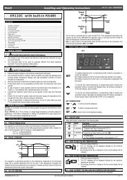
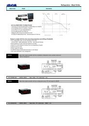
HOJA TÉCNICA 5231H000 Edición 05<br />
(01 de 06)<br />
<strong>Cable</strong> <strong>calefactor</strong> <strong><strong>para</strong>lelo</strong> <strong>potencia</strong>/m <strong>constante</strong><br />
<strong>para</strong> protección de suelos en cámaras frigoríficas.<br />
Constant wattage W/m <strong>para</strong>llel heating cable<br />
for "frost heave" protection in cold room stores<br />
www.ako.<strong>com</strong><br />
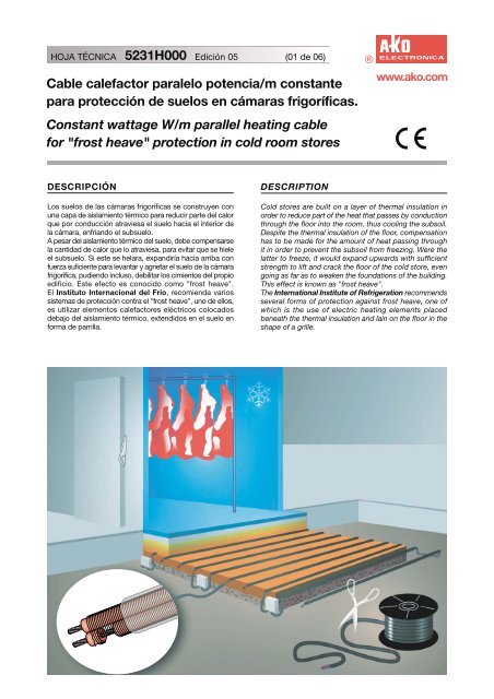
DESCRIPCIÓN<br />
Los suelos de las cámaras frigoríficas se construyen con<br />
una capa de aislamiento térmico <strong>para</strong> reducir parte del calor<br />
que por conducción atraviesa el suelo hacia el interior de<br />
la cámara, enfriando el subsuelo.<br />
A pesar del aislamiento térmico del suelo, debe <strong>com</strong>pensarse<br />
la cantidad de calor que lo atraviesa, <strong>para</strong> evitar que se hiele<br />
el subsuelo. Si este se helara, expandiría hacia arriba con<br />
fuerza suficiente <strong>para</strong> levantar y agrietar el suelo de la cámara<br />
frigorífica, pudiendo incluso, debilitar los cimientos del propio<br />
edificio. Este efecto es conocido <strong>com</strong>o "frost heave".<br />
El Instituto Internacional del Frío, re<strong>com</strong>ienda varios<br />
sistemas de protección contra el "frost heave", uno de ellos,<br />
es utilizar elementos <strong>calefactor</strong>es eléctricos colocados<br />
debajo del aislamiento térmico, extendidos en el suelo en<br />
forma de parrilla.<br />
DESCRIPTION<br />
Cold stores are built on a layer of thermal insulation in<br />
order to reduce part of the heat that passes by conduction<br />
through the floor into the room, thus cooling the subsoil.<br />
Despite the thermal insulation of the floor, <strong>com</strong>pensation<br />
has to be made for the amount of heat passing through<br />
it in order to prevent the subsoil from freezing. Were the<br />
latter to freeze, it would expand upwards with sufficient<br />
strength to lift and crack the floor of the cold store, even<br />
going as far as to weaken the foundations of the building.<br />
This effect is known as "frost heave".<br />
The International Institute of Refrigeration re<strong>com</strong>mends<br />
several forms of protection against frost heave, one of<br />
which is the use of electric heating elements placed<br />
beneath the thermal insulation and lain on the floor in the<br />
shape of a grille.
HOJA TÉCNICA 5231H000 Edición 05<br />
(02 de 06) www.ako.<strong>com</strong><br />
CABLE CALEFACTOR<br />
El cable <strong>calefactor</strong> AKO-5231, ha sido especialmente<br />
diseñado <strong>para</strong> este sistema de protección y proporciona<br />
ventajas <strong>com</strong>o:<br />
• Facilidad de instalación<br />
El cable proporciona unos vatios por metro <strong>constante</strong>s<br />
independientemente de su longitud. Ello permite cortarlo<br />
a medida en obra en el momento de su instalación.<br />
• Seguridad a bajo coste de instalación<br />
y mantenimiento<br />
Todo ello, hace que sea la mejor solución técnica y<br />
económica <strong>para</strong> evitar el problema expuesto en la<br />
descripción.<br />
CARACTERÍSTICAS<br />
El cable <strong>calefactor</strong> AKO-5231, es de tipo <strong><strong>para</strong>lelo</strong> y <strong>potencia</strong><br />
de entrega por metro lineal <strong>constante</strong>. Se caracteriza porque<br />
el conductor de calentamiento, está enrollado en espiral<br />
alrededor de los dos conductores aislados del cable, con<br />
los que hace contacto alternativamente en unos puntos<br />
determinados. El cable va formando internamente, un<br />
sistema de muchas resistencias en <strong><strong>para</strong>lelo</strong> alimentadas<br />
por los dos conductores.<br />
HEATING CABLE<br />
The AKO-5231 heating cable has been especially<br />
designed for this protection system and offers advantages<br />
such as:<br />
• Easy installation<br />
The cable ensures a constant wattage per metre, no matter<br />
what its length. This means that the cable can be cut-tolength<br />
on site at the moment of its installation.<br />
• Safety at a low installation and<br />
maintenance costs<br />
These advantages make this the best and cheapest<br />
technical solution for avoiding the problem explained in<br />
the section entitled "Description".<br />
CHARACTERISTICS<br />
The AKO-5231 heating cable is of the <strong>para</strong>llel type with<br />
constant wattage per linear metre. It is characterised by<br />
its heating conductor element that coils spirally around<br />
the two insulated cable conductors, with which it makes<br />
alternate contact at specific points. The cable forms an<br />
internal system consisting of several <strong>para</strong>llel resistances<br />
that are fed by the two conductors.<br />
Extremo frío final<br />
Cold end-seal<br />
Kit de conexión + final / End seal + connection kit<br />
Tramo <strong>calefactor</strong> / Heating lenght<br />
Extremo frío de conexión<br />
Connection end cold<br />
230 V<br />
A<br />
C<br />
230 V<br />
A<br />
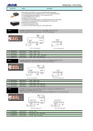
ESQUEMA INTERIOR<br />
INTERNAL DIAGRAM<br />
B<br />
Conductor de calentamiento<br />
Heating conductor element<br />
C<br />
Distancia entre contactos<br />
Heating zone lenght<br />
D<br />
Conductores<br />
Conductors<br />
230 V<br />
B<br />
D<br />
A<br />
C<br />
230 V<br />
CORTE A MEDIDA<br />
CUT-TO-LENGTH<br />
B<br />
D<br />
Al aplicar tensión entre los dos conductores del cable, el<br />
conductor de calentamiento recibe esta misma tensión<br />
entre los puntos de contacto A-B, B-C, C-D, etc. Ello<br />
hace que la <strong>potencia</strong> de entrega por metro lineal de cable<br />
sea <strong>constante</strong> e independiente de la longitud del mismo,<br />
o sea, a más longitud de cable mas <strong>potencia</strong> total, pero<br />
la <strong>potencia</strong> por metro lineal continua siendo la misma.<br />
Este tipo de cable, permite que pueda ser cortado y<br />
terminado a medida en obra, a cualquier longitud múltiple<br />
de la distancia entre contactos, y conectarse a 230 V.<br />
On applying voltage between the two cable conductors,<br />
the heating conductor element receives this same voltage<br />
between contact points A-B, B-C, C-D, etc. This means<br />
that the output power per linear metre of cable remains<br />
constant and independent of the cable length: the longer<br />
the cable, the greater the total power, but the power per<br />
linear metre is always the same. This kind of cable can<br />
be cut-to-length and finished on site, no matter what the<br />
multiple length of the heating zone and to be connected<br />
to 230 V supply.<br />
ESPECIFICACIONES TÉCNICAS / TECHNICAL SPECIFICATIONS<br />
Ref. de catálogo / Catalogue number<br />
Potencia de entrega a 230 V / Power output at 230 V:<br />
Temperatura máx. de exposición (desconectado):<br />
Max. exposure temperature (power off):<br />
Longitud máxima de circuito / Maximum circuit length:<br />
Distancia entre contactos / Heating zone length:<br />
Tensión de ensayo / Test voltage:<br />
Dimensiones exteriores nominales<br />
Nominal outer dimensions:<br />
Longitud bobina de suministro: / Standard reel length:<br />
Normas de referencia / Standard reference:<br />
Datos con más información en Hoja Técnica:<br />
Further information in Data Sheet:<br />
AKO-5231<br />
10 W/m<br />
70ºC<br />
70ºC<br />
150 m<br />
1000 mm<br />
1500 V<br />
7 x 9,5 mm<br />
7 x 9,5 mm<br />
100 m<br />
UNE 21155, CEI 800<br />
1212H001<br />
1212H001
HOJA TÉCNICA 5231H000 Edición 05<br />
(03 de 06) www.ako.<strong>com</strong><br />
METROS DE CABLE A INSTALAR<br />
La <strong>potencia</strong> necesaria <strong>para</strong> evitar la congelación del The wattage required in order to avoid frost heave in<br />
subsuelo de las cámaras frigoríficas no sobrepasa cold stores is normally no higher than 20 W/m 2 . Given<br />
habitualmente los 20 W/m 2 . Debido a que por las inercias that thermal inertia makes it inadvisable for the distance<br />
térmicas no es aconsejable que la distancia entre cables between heating cables to be over 500 mm, and that<br />
<strong>calefactor</strong>es sea superior a 500 mm y el cable es de 10 the cable is of 10 W/m, the following is normally<br />
W/m normalmente se instalan:<br />
installed:<br />
• 2 m de cable AKO-5231 por<br />
• 2 m of AKO-5231 cable per<br />
cada m 2 de superficie de suelo<br />
m 2 of floor surface<br />
COMPROBACIÓN DE PÉRDIDAS<br />
CHECKING FOR LOSSES<br />
A pesar de los metros indicados <strong>com</strong>o los habituales, Despite the standard length given above, a control<br />
deberá <strong>com</strong>probarse que las pérdidas a través del must be carried out to ensure that losses through the<br />
aislamiento térmico del suelo, no sean superiores a los thermal insulation of the floor are no higher than 20<br />
20 W/m 2 indicados. Para ello se utilizará la siguiente W/m 2 .<br />
fórmula:<br />
To do this, we will use the following formula:<br />
K x t<br />
Pérdidas en W/m 2 = Losses in W/m<br />
e<br />
2 K x t<br />
=<br />
e<br />
En donde:<br />
Where:<br />
K = Conductividad térmica del aislamiento en<br />
K = Thermal conductivity of the insulation in<br />
W/mºC a 0ºC<br />
W/mºC at 0ºC<br />
t = Diferencia de temperaturas entre la mínima<br />
t = Difference in temperature between the min.<br />
de la cámara y el subsuelo a 0ºC<br />
temperature of the room and the subsoil at 0ºC<br />
e = Espesor del aislamiento térmico del suelo de<br />
e = Thickness of the thermal insulation of the cold<br />
la cámara frigorífica en metros<br />
store floor in metres<br />
Al valor así obtenido, se le añadirá un coeficiente de We have to add a safety coefficient of 45% to the value<br />
seguridad del 45% <strong>para</strong> <strong>com</strong>pensar defectos en el obtained in this manner in order to <strong>com</strong>pensate for faults<br />
aislamiento térmico, variaciones en la tensión de in the thermal insulation, variations in the electric input<br />
alimentación eléctrica, tolerancias de la <strong>potencia</strong> de voltage, tolerances of the output power in the manufacture<br />
entrega en la fabricación del cable, etc.<br />
of the cable, etc.<br />
Ejemplo:<br />
Example:<br />
Supongamos una cámara frigorífica con las siguientes Let's take a cold store room with the following<br />
características:<br />
characteristics:<br />
K = Conductividad térmica del aislamiento a 0ºC<br />
K = Thermal conductivity of the insulation at 0ºC =<br />
de 0,043 W/mºC<br />
0.043 W/mºC<br />
t = Temperatura mínima de la cámara de -40ºC<br />
t = Minimum room temperature = -40ºC<br />
e = Espesor del aislamiento térmico del suelo de<br />
e = Thickness of the thermal insulation of the<br />
150 mm<br />
floor = 150 mm<br />
0,043 x 40<br />
Pérdidas en W/m 2 = x 1,45 =16,62 W/m 2 0,043 x 40<br />
Losses in W/m 2 = x 1,45 =16,62 W/m 2<br />
0,150<br />
El valor así obtenido, es inferior a los 20 W/m 2 , si fuera<br />
superior, debería reducirse la distancia entre los cables<br />
<strong>calefactor</strong>es, aumentando los metros de cable por metro<br />
de superficie de suelo de la cámara, <strong>para</strong> conseguir los<br />
W/m 2 necesarios.<br />
ACCESORIOS<br />
LENGTH OF CABLE TO BE INSTALLED<br />
0,150<br />
The value obtained in this manner is lower than 20 W/m 2 .<br />
If it were any higher than this, the distance between the<br />
heating cables would have to be reduced, and the length<br />
of cable per square metre of floor within the room<br />
increased, in order to achieve the required W/m 2 .<br />
ACCESSORIES<br />
Para conseguir una correcta instalación del cable <strong>calefactor</strong><br />
y un buen funcionamiento de la instalación, deberán<br />
utilizarse los accesorios adecuados, de los que, en sus<br />
Hojas Técnicas correspondientes, se detallan todas sus<br />
características.<br />
In order to ensure that the heating cable is correctly<br />
installed and that the installation is running properly, the<br />
appropriate accessories must be used. The characteristics<br />
of these accessories are described in the corresponding<br />
Data Sheet:<br />
AKO-12191<br />
Kit <strong>para</strong> extremos<br />
de conexión y final<br />
End-seal and<br />
connection kit<br />
M 20<br />
AKO-12192<br />
Kit de empalme<br />
Splice kit<br />
Hasta 70ºC<br />
Up to 70ºC<br />
<strong>Cable</strong> <strong>calefactor</strong><br />
Heating cable<br />
Hasta 70ºC<br />
Up to 70ºC<br />
<strong>Cable</strong> de alimentación<br />
Power supply cable<br />
Caja de conexión<br />
Junction box<br />
ref. AKO-71610<br />
Termostato electrónico<br />
Electronic thermostat<br />
ref. AKO-1520<br />
Caja de protección <strong>para</strong> termostato<br />
Protection box for the thermostat<br />
ref. AKO-15592A<br />
(AKO-1520) + (AKO-15592A)
HOJA TÉCNICA 5231H000 Edición 05<br />
(04 de 06) www.ako.<strong>com</strong><br />
Sonda PTC de longitud a escoger de entre las que se indican<br />
1,5 m ref. AKO-155801<br />
2,0 m ref. AKO-155802<br />
Las sondas deben instalarse de forma que sean<br />
recuperables y también pueden prolongarse mediante<br />
cable apantallado<br />
3,0 m ref. AKO-155803<br />
7,0 m ref. AKO-155807<br />
Length probe PTC to be selected from the following models:<br />
15 m ref. AKO-155815<br />
30 m ref. AKO-155830<br />
The probes must be installed in such a way that they can<br />
be recovered and, when required, extended by means of<br />
a shielded cable.<br />
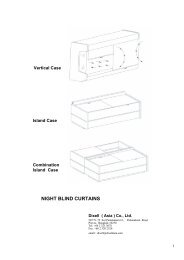
INSTRUCCIONES DE APLICACIÓN<br />
Los cables <strong>calefactor</strong>es se instalarán en tramos rectos<br />
formando una parrilla con una distancia máxima entre ellos<br />
de 500 mm. Como medida de seguridad, los cables se<br />
instalarán bajo tubo de plástico <strong>para</strong> protección, con un<br />
diámetro interior mínimo de 19 mm.<br />
Siempre que se tenga accesibilidad por dos lados opuestos<br />
del suelo de la cámara y <strong>para</strong> facilitar la instalación, ésta,<br />
se realizará de acuerdo al ejemplo que exponemos.<br />
APPLICATION INSTRUCTIONS<br />
The heating cables must be installed in straight lines<br />
forming a grille shape, and with a maximum distance of<br />
500 mm between each one. For security's sake, the cables<br />
will be installed in plastic protection tubing with a minimum<br />
interior diameter of 19 mm.<br />
The installation will be carried out according to the given<br />
example on the condition that it is possible to reach the<br />
two opposite sides of the cold store floor.<br />
Tubo de plástico Ø interior mínimo de 19 mm<br />
Plastic tubing with a minimum interior Ø of 19 mm<br />
Distancia máx. entre cables / Max. distance between cables<br />
500 mm. 500 mm. 500 mm.<br />
Enlosado / Tiles<br />
Hormigón / Concrete<br />
Capa aislante<br />
Insulating layer<br />
<strong>Cable</strong> <strong>calefactor</strong><br />
Heating cable<br />
Caja de conexión<br />
Junction box<br />
Inclinación <strong>para</strong> evitar entrada de agua en<br />
instalaciones intemperie<br />
Slope to prevent the entry of water in<br />
outdoor installations<br />
A<br />
= =<br />
Sensor termostato A / Thermostat sensor A<br />
B<br />
<strong>Cable</strong> <strong>calefactor</strong><br />
y barrera de vapor<br />
Heating cable<br />
and steam barrier<br />
Base / Hard core<br />
Subsuelo / Subsoil<br />
Sensor termostato B / Thermostat sensor B<br />
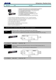
Si no se dispone de dos lados opuestos con accesibilidad,<br />
pueden adoptarse diversas soluciones, de las que<br />
exponemos algunas a título de ejemplo:<br />
A<br />
Instalar cajas de registro en el suelo <strong>para</strong> unir los tramos<br />
rectos de los tubos, que permitan una fácil instalación y<br />
mantenimiento.<br />
If the two opposite sides of the floor cannot be reached,<br />
different solutions can be adopted; some of which are<br />
given below by way of an example:<br />
Install manhole boxes in the floor through which to join<br />
the straight stretches of tubing, thereby permitting easy<br />
installation and maintenance.<br />
500<br />
mm<br />
500<br />
mm<br />
500<br />
mm<br />
B<br />
Instalar cajas de empalme situadas en la parte inferior de<br />
las paredes laterales. Se situarán en la parte exterior de<br />
la cámara ya que no deben estar expuestas a temperaturas<br />
inferiores a -15ºC.<br />
Install junction boxes to the lower part of the side walls.<br />
These will be placed outside the room since they must<br />
not be exposed to temperatures lower than -15ºC.<br />
500 mm<br />
500 mm<br />
500 mm
HOJA TÉCNICA 5231H000 Edición 05<br />
(05 de 06) www.ako.<strong>com</strong><br />
C<br />
Instalar cajas de empalme enterradas debajo del<br />
aislamiento térmico y a la misma altura que los tubos,<br />
situadas a 500 mm de las paredes laterales.<br />
Install junction boxes beneath the thermal insulation and<br />
at the same height as the tubes, at 500 mm from the side<br />
walls.<br />
500<br />
mm<br />
500<br />
mm<br />
500<br />
mm<br />
500<br />
mm<br />
D<br />
Instalar doble circuito de cable <strong>calefactor</strong> (uno de servicio<br />
y uno de reserva) enterrando directamente los cables sin<br />
tubo de protección. En este caso, el tipo de cable a utilizar<br />
debe ser con trenza metálica de protección más cubierta<br />
exterior de fluoropolímero. Debe consultarse a AKO el<br />
modelo más adecuado.<br />
• Los dos cables se instalarán juntos , quedando uno en<br />
servicio, regulado por los termostatos y el otro de reserva<br />
que se dejará inactivo. Los dos cables se instalarán con<br />
todos sus kits y hasta el interior de las cajas de conexión.<br />
• Los extremos finales deben quedar en el exterior y en el<br />
mismo lado que las cajas de conexión.<br />
• El circuito de reserva quedará sin alimentar hasta una<br />
eventual utilización en caso de que se produjera alguna<br />
anomalía debida a la instalación.<br />
• Instalado el cable con los kits correspondientes y<br />
conexionado a las cajas de alimentación, inmediatamente<br />
después de colocado el mortero de nivelación y antes de<br />
cubrirlo con el aislamiento, es necesario medir y <strong>com</strong>probar:<br />
- La resistencia de aislamiento, la cual será medida entre<br />
los dos conductores unidos y la trenza metálica. La<br />
medida se realizará mediante un megóhmetro a 500 Vcc,<br />
debiéndose obtener un valor superior a 20 M <strong>para</strong><br />
cables de longitud inferior a 75 m, o a [(1500 M .m) /<br />
longitud en m] <strong>para</strong> cables con longitudes superiores.<br />
- Dar tensión al cable <strong>para</strong> <strong>com</strong>probar que no saltan<br />
diferencial ni magnetotérmico.<br />
- Comprobar que la intensidad del cable corresponde a<br />
la cantidad de metros instalados.<br />
En el caso de que alguna medición no haya sido correcta,<br />
extraer el cable y revisarlo. Por este motivo es imprescindible<br />
que las mediciones se efectúen inmediatamente, ya que<br />
una vez el hormigón esté seco el cable <strong>calefactor</strong> ya no<br />
es recuperable.<br />
500<br />
mm<br />
Install heating cable with a double circuit (one in service<br />
and one as a standby), directly burying the cables without<br />
a protection tube. In this case, the cable to use must be<br />
with braided metal and fluoropolymer sheath. The suitable<br />
model must be request to AKO.<br />
• The two cables will be installed together. The cable in<br />
service will be controlled by the thermostats and the other<br />
standby cable will be left inactive. Both cables will be<br />
installed with all of their kits and must reach the inside of<br />
the junction boxes.<br />
• The end-seal must be in the outside at the same side<br />
as the input boxes.<br />
• The standby circuit will not be activated unless it is<br />
required for use due to a fault in the installation.<br />
• Once the cable with its corresponding kits has been<br />
connected to the input boxes, and immediately after having<br />
lain the levelling mortar, but before covering it with the<br />
insulating layer, the following must be gauged and checked:<br />
- The fault resistance, which will be measured between<br />
both united conductors and the metallic braid. Measurement<br />
shall be taken with a megger at 500 VDC, it shall<br />
have a fault resistance of at least 20 M for cables<br />
shorter than 75 m, or [(1500 M .m) / lenght in m] for<br />
cables over 75 m.<br />
- Energise the cable to ensure that neither the leakage<br />
detection nor the circuit breaker switches blow.<br />
- Check that the intensity of the cable corresponds to the<br />
number of metres installed.<br />
Should any of the measurements not have past the test<br />
correctly, remove the cable and check it. This is why the<br />
measurements must be taken immediately because, once<br />
the concrete has dried, it is no longer possible to remove<br />
the heating cable.<br />
500<br />
mm
HOJA TÉCNICA 5231H000 Edición 05<br />
(06 de 06) www.ako.<strong>com</strong><br />
CONTROL DE TEMPERATURA<br />
Es aconsejable la instalación de 2 termostatos electrónicos<br />
<strong>para</strong> controlar la temperatura.<br />
A/ Termostato AKO-1520 con una temperatura de ajuste<br />
(set point) entre 5ºC y 10ºC, con el sensor de la sonda<br />
situada en el punto más desfavorable y equidistante entre<br />
dos cables <strong>calefactor</strong>es, que permitirá controlar y visualizar<br />
la temperatura del suelo y ahorrar energía.<br />
B/ Termostato AKO-1520 con una temperatura de ajuste<br />
(set point) de 30ºC, con el sensor de la sonda situada<br />
tocando al cable <strong>calefactor</strong> y en el interior del tubo de<br />
protección, <strong>para</strong> controlar la temperatura del cable.<br />
Si el termostato que es <strong>para</strong> montar sobre raíl DIN, no se<br />
instala en el interior de un cuadro eléctrico, se hará dentro<br />
de una caja AKO-15592A de protección IP65.<br />
Ejemplo esquema conexión eléctrica<br />
TEMPERATURE CONTROL<br />
It is advisable to install 2 electric thermostats for controlling<br />
the temperature.<br />
A/ AKO-1520 thermostat with a temperature Set point of<br />
between 5ºC and 10ºC, placing the probe sensor at the<br />
most unfavourable point and at an equal distance between<br />
the two heating cables, in order to see and control the<br />
ground temperature and save energy.<br />
B/ AKO-1520 thermostat with a temperature Set point of<br />
30ºC, with the probe sensor touching the heating cable<br />
and placed inside the protection tube in order to control<br />
the cable temperature.<br />
If the thermostat, to be fitted to a DIN rail, is not installed<br />
inside an electrical panel board, it must be placed in an<br />
AKO-15592A box with IP65 protection.<br />
Example of the layout of an electric connection<br />
SONDA A PROBE<br />
SONDA B PROBE<br />
AKO-71610<br />
AKO-12191 AKO-71610 AKO-12191 AKO-71610 AKO-12191<br />
AKO-1520<br />
AKO-1520<br />
6 7<br />
6 7<br />
1 2 3<br />
10 11<br />
1 2 3<br />
10 11<br />
N R S T<br />
Tensión de maniobra<br />
Control voltage<br />
400 V ± 10%<br />
230 V ± 10%<br />
230 V ± 10%<br />
355231000 REV. 04 2003<br />
D.L.: B-7932-2003