dx_cat 06 monitoring system.pdf - Acr-asia.com
dx_cat 06 monitoring system.pdf - Acr-asia.com
dx_cat 06 monitoring system.pdf - Acr-asia.com

Create successful ePaper yourself
Turn your PDF publications into a flip-book with our unique Google optimized e-Paper software.
CONTROLLING & SUPERVISING SYSTEMSSECTION INDEXFUNCTIONSXJ500-XVIEW - CONTROLLING AND MONITORINGControlling and <strong>monitoring</strong> <strong>system</strong>XJ500 management softwareXWEB300 - ALARM MANAGEMENT AND CONTROLLING - WEB TECHNOLOGYAlarm and control Web ServerXWEB3000 - CONTROLLING, MONITORING AND SUPERVISING - WEB TECHNOLOGYControlling, <strong>monitoring</strong> and supervising Web ServerICOOLL - WIRELESS NETWORK MODULESTx/Rx modules for wireless networkXJA-XJP-XJR - RELAY AND ACQUISITION MODULESRelay moduleTemperature/humidity/pressure probe acquisition modulesAlarm acquisition modulesXJA-XJP-XJR series parametersMODELSXJ500XVIEWXWEB300XWEB3000XJ100 - XJ150XJR40DXJP30D - XJP40D - XJP60DXJA50D - XJA50SL132132134136136139139143143144145145145146131
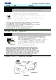
165x80mmXJ500 - XVIEW: CONTROLLING AND MONITORING SYSTEMAPPLICATIONS: extremely well suited for all the refrigerated installations, both small, such as mini-markets, petrol stations, small shops and for largersites such as food warehouses, supermarkets, hypermarkets with up to 225 controllers. XJ500 can also be used in all production and storage goodsprocesses such as fast-food, restaurants, <strong>cat</strong>ering, even for medical and pharmaceutical appli<strong>cat</strong>ions or conservation of old documents and works ofart. The <strong>monitoring</strong> <strong>system</strong> can work alone or with the XView software supplied and used on local PC or remote PC (via modem) connection.• Controlling and <strong>monitoring</strong> unit connectable to any Dixell controller equipped with a serial <strong>com</strong>muni<strong>cat</strong>ion output• Monitoring and checking of all temperature, humidity and pressure values <strong>com</strong>ing from the devices as far as their staus such as defrost, energysaving, continous cycle and On/Off• Alarms management via FAX, SMS or locally by means of alarm relay or a buzzer• Scheduled <strong>com</strong>mands via the network for defrost, ON/OFF, AUX, ...in real time by means of the XJ500’s internal RTC, either to a single controlleror a group of them• User friendly interface for stand alone usage of the unit even without a PC• Bright LCD display for a rapid viewing of status, actual and historical alarms and all recorded data• Local or remote connection to a PC by means of XView software, bundled with the unit, to allow the user to simply manage advanced featuressuch as layout or schematic view of the plant• 4 on board relays: 1 for modem reset, 1 for alarm and 2 for auxiliary loads• 2MB internal memory, expandable to 10MB to store 1 year of data with 15min sampling time (12 or 60 controllers)• Standard <strong>com</strong>muni<strong>cat</strong>ion protocol ModBUS-RTU• Desk or wall mounting• 10VA max power absorption• LCD back lit display with 4 lines x 20 characters per lineInputs: power supply: 24Vac or 110/230Vac ±10%serial line: RS485 for device (ModBUS–RTU) connectionbackup battery: 3,5 – 12V (external)Sampling time: programmable from 1 to 255 minutesOutputs: printer: 25 pin parallel connectorRS232: 9 pin serial connectoralarm relay: 8A/230Vacalarm relay 1 and 2: 8A/230VacInternal memory: 2MB standard, 10MB optionalHOW TO ORDERXJ500X J 5 0 0 - A 0 0 0 EAEPower supply Memory2 = 24Vac/dc6 = 110/230Vac01= 2MB (standard)= 10MB132 CONTROLLING & SUPERVISING SYSTEMS
XVIEW: XJ500 MANAGEMENT SOFTWAREBeing Windows based, XView PC software for the XJ500 is extremelysimple to use. It allows the XJ500 to be connected to a local PC(via cable) or to a remote PC (via modem). All data in the XJ500’smemory can then be downloaded and stored on the PC. The new”Run Time” function allows the user to view all data such as temperatures,pressures, alarms and controller status directly on the PC in”Real Time”. From the PC, the user can send a variety of <strong>com</strong>mandsto each individual controller, for example, to initiate a defrost cycle,to put a controller into standby or to activate it’s auxiliary relay(if available). Controller Set Points can also be adjusted from thePC. Service engineers can access the parameters of any controllerconnected to the <strong>system</strong> in order to make any modifi<strong>cat</strong>ions thatmay be necessary.SET UPSystem configuration of XJ500 is quickly achieved using the ”Set Up” section of the XView software, <strong>com</strong>posed of four easy to use windows.Window for configuration of passwords, data acquisition, alarms and localprinterWindow for configuration of modem, FAX and SMS dial outsWindow for configuration of <strong>system</strong> devices (controllers)Window for configuration of ”special function” timers134 CONTROLLING & SUPERVISING SYSTEMS
RUN TIMEThis function introduces a new window that allows the userto view in ”Real Time”, either on a local or a remote PC, datafrom every device connected to the <strong>system</strong>, such as temperatures,pressures, alarms andcontroller status.Main Real Timefunction windowReal Time function:instrument set pointprogrammingReal Time function:detailled alarms windowData archive:graph mode datavisualizationGRAPHICS, PARAMETER TABLEPROGRAMMING AND DATA EXPORTIt’s possible to download on a PC, all the data stored in XJ500memory and then show them either in graph or table format.The data can be also exported in a standard format that canbe used by Microsoft Excel.Instruments tableprogramming windowData archive: table modedata visualizationLAYOUTThanks to its powerful graphic tool, the new layout functionallows the user to acces advanced features in the supervisingand management of the refrigeration units simply witha single click of the mouse.Layout function:graphic editor andreal time windowCONTROLLING & SUPERVISING SYSTEMS 135
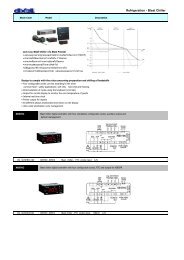
DIN RailXWEB300: ALARM AND CONTROLLING WEB SERVERAPPLICATIONS: it is extremely well suited for 12 or 24 device installations such as petrol stations, mini-market, small storage centres. The reduceddimensions (4 DIN) and the absence of local user interface make the XWEB300 the ideal solution for the remote connection / assistance (via modem) tothe plant. Local or remote connection from PC is made without the need for special software, only standard web browser (Microsoft Internet Explorer®or Netscape®) software is needed; the information is displayed as Web pages. The <strong>com</strong>petitive price lets you to use this Web Server in appli<strong>cat</strong>ions witha only a single regulator such as <strong>com</strong>pressor rack and medical close control.• Data capture and alarm <strong>monitoring</strong> WEB server connectable to Dixell’scontrollers with serial output or to others ModBUS-RTU <strong>com</strong>patible devices• Based on µc-Linux operative <strong>system</strong> with internal WEB pages• Data shown for all controller values, parameters programming and alarms• Powerful graphs showing and exporting functions in TXT or HTML format• Calendar function to filter alarm transmission to a particular service• Alarm sending via FAX, SMS (GSM modem needed) or e-mail• Local or remote connection to a PC via serial cable or modem, data display and<strong>monitoring</strong> with a standard browser (Microsoft Internet Explorer® o Netscape®)• Open collector output to transmit alarms• 4MB internal memory to store up to 1 year data recorded with 15 min samplingtime and 12 or 24 controllers with 1 analog input and 2 digital status each• Standard <strong>com</strong>muni<strong>cat</strong>ion protocol ModBUS-RTU• 3VA max power absorptionInputs: power supply: 24Vac or 110/230Vac ±10%serial line: RS485 for device (ModBUS–RTU) connectionSampling time: programmable from 1 to 60 minutesInternal memory: 4MB standardOutputs:RS232: for modem connectionRS232: for PC connectionopen collector: 12Vdc-50mAreset modem relay: 1A/230VacHOW TO ORDERXWEB300/12 X W E B 3 0 0 - A - 1 2 0XWEB300/24 X W E B 3 0 0 - A - 2 4 0APower supply2 = 24Vac4 = 110Vac5 = 230Vac136 CONTROLLING & SUPERVISING SYSTEMS
LOCAL CONNECTIONBy means of a local connection, the XWEB300 can be easilyupdated and configured prior to installation.During operation the User is allowed to be interfaced in realtime and to download all the data <strong>com</strong>ing from the connecteddevices, in order to analyse the database with thepowerful graph functions of the XWEB itself. The User cancheck alarm events or verify the efficiency of the machineryafter any kind of maintenance operations.RS485 NETWORKLOCAL PCSTANDARD BROWSERREMOTE CONNECTIONThe XWEB300 program can be easily updated and configured from a remote connection via modem. When there is a problem with the machinery theremote connection shows, in real time, the status of the malfunction. This helps the User take the right decision and to obtain easy and rapid resolutionof the problem (for example: alarm reset or change the setpoint value). It is possible to check the functioning of a prototype or overcharged unitsbecause of less than ideal operating conditions. In this way we can avoid the engagement of qualified and expensive personnel.RS485 NETWORKPROVIDERE-MAIL*SMSALARMPORTABLEPHONEFAX* only with GSM modemXWEB MODEMPORTABLE PHONESMARTPHONEPDAMONITORING & CONTROLLINGMODEMLOCAL PCSTANDARD BROWSERCONNECTION VIA POCKET PC (PDA)When the connection is made by means of a Pocket PC (PDA),XWEB300 automatically recognises this and makes severaldedi<strong>cat</strong>ed pages available.On them it is possible to display all the values of a device andsend it <strong>com</strong>mands.CONTROLLING & SUPERVISING SYSTEMS 137
MAIN WINDOWSThe status of the devices connected (also from different manufacturers)is displayed simply and clearly even if <strong>com</strong>prehensive informationfrom the instrument is being displayed.Thanks to the XWEB300, the user has an intuitive, powerful and atthe same time, very versatile way, that allows him/her to modify allthe various functioning parameters of the instruments.The alarm archive allows customers to see up to 100 alarms foreach instrument, giving users <strong>com</strong>plete information about the type,starting and stopping dates and times.The XWEB300 has lots of main features such as protection and security,this is why a special function can supply a <strong>com</strong>plete operationlist that users have done.The XWEB300 can supply powerful graphs, able to represent multipleanalogue variables on the same pictorial <strong>system</strong> and the courseof the status of the outputs and alarms.138 CONTROLLING & SUPERVISING SYSTEMS
350x235mmXWEB3000: CONTROLLING, MONITORING AND SUPERVISING WEB SERVERAPPLICATIONS: it is extremely well suited for larger installations with up to 247 devices such as supermarkets, hypermarkets or large storage anddistribution centres as well as production and storage goods processing such as fast-food, restaurants, <strong>cat</strong>ering up to medical and pharmaceuticalappli<strong>cat</strong>ions. This Web Server is very well know for its connection characteristics and is ideal for the large service centre needs (modem, ethernet andinternet connection); XWEB3000 can also work without a PC but only via monitor, keyboard and mouse connection. Local or remote connection fromPC is made without using a special software, standard web browser software (Microsoft Internet Explorer® or Netscape®) is all that’s required; Informationis displayed as Web pages.• Data capture and alarm <strong>monitoring</strong> WEB server connectable to Dixell’s controllers with serial output or to others ModBUS-RTU <strong>com</strong>patible devices• Based on Linux operative <strong>system</strong> with internal WEB pages• All controller values can be showed using a special “Single View” window or using “Run Time” window many controllers can be viewed at the sametime. It is even possible to use a “Layout” view of the plant with pictures and schematics drawings• Powerfull tool to view graphs and export in Microsoft Excel® format• Easy plant management by means of the “Scheduler” to send <strong>com</strong>mands according to a custom calendar• Parameter and alarm management with different levels of typology• Calendar function and internal RTC both for alarm transmission to the “in charge” service and <strong>com</strong>mand sending to the controllers• Possibility to divide the controllers set in different <strong>cat</strong>egories of products with their own sampling time• Alarm sending via FAX, SMS or e-mail• Local or remote connection to a PC or a PDA with a standard browser (Microsoft Internet Explorer® o Netscape®)• Standard <strong>com</strong>muni<strong>cat</strong>ion protocol ModBUS-RTU• 19” RACK or desk mounting• 50VA max power absorptionInputs: power supply: 110/230Vac ±10%serial line: RS485 for device (ModBUS–RTU) connectionSampling time: programmable from 1 to 255 minutesInternal memory: 128MBCPU:1GHzHard disk: 40GBHOW TO ORDEROutputs:RS232: serial port (COM port)AUX alarm relay: 2x 8A/230Vac<strong>system</strong> alarm relay: 8A/230VacRJ45: UTP <strong>cat</strong>. 5 cable connector (LAN port)RJ11: telephone line connector (line)printer: 25 pin parallel connectorPS/2: keyboard/mouse connectorVGA: video output connectorUSB: 2x modem and <strong>com</strong>patible peripheralXWEB3000X W E B 3 0 0 0 - 6 0 0 0 EEInternal modem0 = No1 = YesCONTROLLING & SUPERVISING SYSTEMS 139
REMOTE CONNECTIONSXWEB3000 Server, installed in the <strong>system</strong> to monitor, can be remotelylinked by several methods:• by direct Internet connection, if provided with a static IP address;• by link in local Ethernet network,by means of standard net connector RJ45;• by Modem withpoint to point connection.printerkeyboard / mouseUSBPower supplyRS485 linerelay outputsLANCOMportmonitorWORLD WIDE WEB CONNECTIONRS485 NETWORKROUTERPROVIDERPROVIDERROUTERREMOTE PCSTANDARD BROWSERPORTABLE PHONEPDAREMOTE PCSTANDARD BROWSERLOCAL ETHERNET CONNECTIONSMARTPHONERS485 NETWORKREMOTE PCSTANDARD BROWSERPOINT TO POINT CONNECTIONRS485 NETWORKPDAREMOTE PCSTANDARD BROWSER*MODEMREMOTE PCSTANDARD BROWSERXWEB MODEMPORTABLE PHONEPDA* or with internal modemSMARTPHONE140 CONTROLLING & SUPERVISING SYSTEMS
DEVICE CONFIGURATION & ALARM MANAGEMENTWith XWEB3000, the user is free to create a set of options and rules thatcan range from the configuration of a simple <strong>system</strong> to the association ofspecial options for any devices connected and manifold rules for alarms.VIEW OF DEVICESThe Run Time function displays many devices together in a unique window.This is dynamic page and the data showed is updated in real time.The status of the devices connected(also from different manufacturers)is displayed simply and clearly evenif <strong>com</strong>prehensive information fromthe instrument is being displayed.Thanks to the XWEB3000, the user has an intuitive, powerful and at thesame time, very versatile device, that allows him/her to modify the variousfunctioning parameters of the instruments.SCHEDULERThe scheduler is a powerful graphic tool to manage <strong>com</strong>mands sendingto the controllers. In a very fast way it is possible to have an overviewof all the daily activity. This means that energy savings projects ordefrost can be scheduled easier.SUPERVISINGXWEB3000 has the ability to send supervising <strong>com</strong>mands. For example it’s possible to broadcast to the devices selected, an Energy Saving <strong>com</strong>mandfollowing the activation of a digital input due to maximum permissible <strong>system</strong> power being exceeded. The programming of the events is achieved bymeans of a powerful and flexible user friendly interface.CONTROLLING & SUPERVISING SYSTEMS 141
SMS, FAX, e-mail SENDINGNew SMS sending technology through Internet. XWEB3000 uses aspecial mobile <strong>com</strong>pany to send SMS, this allows a service even morereliable than the standard GSM modem. The user can also have all thestatistics regarding the usage of the service. The alarm signalling to theassistance centre can be managed via FAX or e-mail.DATA EXPORTIt is possible to export all data information in a Microsoft Excel® file.The user can later use this information to build graphs or to collectdata. It is possible to select a data interval and filter between differentcontrollers.BACK-UPXWEB3000 is equipped with a new internal back-up tool to have datasafeprotection even in the wrost enviromental usage. The majorityof USB external device are supported. Beside of the recorded data it ispossible to save all the unit setup.LAYOUTA powerful graphic editor that doesn’t require the installation in your PCof any additional software, is what makes XWEB3000 layout the idealsolution. Using this function the user can access all the real time dataof the controllers and even send a <strong>com</strong>mand to a controller or to a setof them.GRAPHICSGraphs are given fundamental importance for the analysis and the diagnosisof appliances connected to the <strong>system</strong> and for the achieving<strong>com</strong>pliance with regulations, of the variables such as the food storagetemperature. To meet this important function, the XWEB3000 can supplypowerful graphs, able to represent multiple analogue variables onthe same pictorial <strong>system</strong> and the course of the status of the outputsand alarms. This allows the user to have a precise snapshot view ofimportant variables, for easy diagnosis of faults.142 CONTROLLING & SUPERVISING SYSTEMS
XJ100XJ10055x80mmXJ100XJ150XWEB3000XWEB300XJ500ICOOLL: MODULES FOR WIRELESS NETWORK• Radio <strong>com</strong>muni<strong>cat</strong>ion <strong>system</strong> for controlling and supervising units• Cover all appli<strong>cat</strong>ion fields, from single benches to cold rooms and <strong>com</strong>pressor racks• The information <strong>com</strong>ing from the controller are transmitted to an XJ100 module and directly sent to theXJ150 connected to the controlling and supervising unit• Possibility to connect many instruments to the same XJ100• XJ100 automatic “bridge” function to increase signal throughput between modules• Easy to use• Less installation time and costs• High flexibility• 0,25VA max power absorption• Operating frequency: 433,5<strong>06</strong>8MHz• Range: 80m (no obstacles)• Wall or panel mounting• Power supply: XJ100 (5Vdc directly from the controller); XJ150 (5Vdc from PWS150J module)Standard:EN61000-6-3 (2001) + EN 61000-6-1 (2001)ETSI EN 300 220-3 V1.1.1 (2000-09)ETSI EN 301 489-3 V1.2.1 (2000) + ETSI EN 301 489-1 V1.2.1 (2000)XJ100XJ150PWS150JRadio-frequency <strong>com</strong>muni<strong>cat</strong>ion module to use with controllersRadio-frequency <strong>com</strong>muni<strong>cat</strong>ion module to use with controlling<strong>system</strong>XJ150 power supplierMEANING OF LEDSXJ100XJ150DATAdata transmission/reception in progressDATAdata transmission/reception in progressFIELDthe module’s detect <strong>com</strong>muni<strong>cat</strong>ion signalTX/RXradio-frequency transmission/reception in progressPOWERthe module is on and operativePOWERthe module is on and operativeCONTROLLING & SUPERVISING SYSTEMS 143
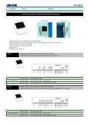
D: DIN RailXJA-XJP-XJR SERIES: RELAY AND ACQUISITION MODULES• 4 relay output modules, managed by <strong>monitoring</strong> <strong>system</strong> (XJR)• Digital inputs for local enable/disable of relays or alarm and status motoring (XJR)• Data acquisition modules suitable for collecting data from any kind of installation (XJP)• Up to 6 inputs for NTC, PTC, 4÷20mA and 0÷10V and 3 digital inputs or 4 Pt100 inputs and 4 digital inputs (XJP)• Up to 10 line voltage inputs (XJA)• Direct line power supply 230 (110)Vac. No external transformer required• Remote display option• Standard <strong>com</strong>muni<strong>cat</strong>ion protocol ModBUS-RTU• Hot Key or Prog tool kit connector for a quick and easy programming• 6VA max power absorptionHOW TO ORDERXJRX J R 4 0 D - A 0 C 0 0APower supplyBuzzerC2 = 24Vac4 = 110Vac5 = 230Vac01= No= YesXJA-XJP30/60XJP40X JD - A B C D EX J P 4 0 D - A B 0 R 4XJA50SL X J A 5 0 S L - A 0 0 0 0ABPower supply Alarm relay Probe inputsMeasurement unitCDDigital inputsE2 = 24Vac4 = 110Vac5 = 230VacC = °CF = °FN = No temperatureO = No1 = YesP = PTCN = NTCR = PT100 (only for XJP40D)A = 4÷20mAW = 0÷10V0 = No3456= 3 digital inputs= 4 digital inputs (only for XJP40D)= 5 digital inputs (only for XJA50D)= 6 digital inputs144 CONTROLLING & SUPERVISING SYSTEMS
XJA-XJP-XJRD: DIN RialRELAY MODULES and PROBE andALARM ACQUISITION MODULESXJA50DXJA50SLXJP30DXJP40DXJP60DXJR40DAlarms/status acquisition modules, without display, ableto read up to 5 + 5 independent inputs (master + slave)Probes and alarms data acquisition modules, withoutdisplay, able to read up to 9 different inputsRelay modules, without display, able to manage 4independent output relaysFEATURESXJA50D XJA50SL XJP30D XJP40D XJP60D XJR40DKeyboard: push buttonsAlimentazioneInputsAnalogueDigital inputs (power supply voltage)Digital inputs (free of voltage contacts)Relay outputsN° 4OtherHot Key/Prog Tool Kit outputRemote display/keyboard outputSerial outputSerial adderssBuzzer*: XJP60D has 3 analogue inputs that are configurable as free of voltage digital inputs24, 110, 230Vac 24, 110, 230Vac 24, 110, 230Vac 24, 110, 230Vac 24, 110, 230Vac5presX-REP/KB1PRGRS4855553x NTC/PTC/4÷20mA/0÷10V33 optpresX-REP/KB1PRGRS48534x Pt1004presX-REP/KB1PRGRS48546*x NTC/PTC/4÷20mA/0÷10V33*presX-REP/KB1PRGRS4856424, 110, 230Vac4no 8A / nc 5ApresKB1PRGRS4851optXJA50D XJA50SL XJP30DXJP40DXJP60DXJR40DKB1-PRG6 key programming keyboardfor XJA50D - XJP30D - XJP40DXJP60D - XJR40DDisplay: n° digits: ± 3 d.p.Keyboard: push buttons: 6The cable CAB/KB11 (1m)is designed to connect thekeyboard with the XJA-XJP-XJR modules100x64mmCONTROLLING & SUPERVISING SYSTEMS 145
PARAMETERSCODEXJA50DXJP30DXJP40DXJP60DXJR40DGENERALAlarm delay at start upAlarm delay after defrostProbe type selectionDecimal point on/offMeasurement unit (°C/°F)Relay 1 polarityPriority switching output 1Relay 2 polarityPriority switching output 2Relay 3 polarityPriority switching output 3Relay 4 polarityPriority switching output 4Polarity digital input 1Setup digital input 1Delay digital input 1Polarity digital input 2Setup digital input 2Delay digital input 2Polarity digital input 3Setup digital input 3Delay digital input 3Polarity digital input 4Setup digital input 4Delay digital input 4Serial address 1Priority sequenceParameters tableSoftware releaseSECTIONSet point2/3 wire probe configuration or n.p.Type of input (probe or D.I.)Maximum alarmMinimum alarmAlarm delayProbe calibrationDigital input 1 configurationDigital input 1 polarityDigital input 2 configurationDigital input 2 polarityDigital input 1 activation delayDigital input 2 activation delayPressure switch activation numberAlarm relay enablingSerial addressdAOEdAPbCrESCFr1Pi1cr2Pi2cr3Pi3cr4Pi4ci1Pi1Fdd1i2Pi2Fdd2i3Pi3Fdd3i4Pi4Fdd4Ad1SeqPtbrELSetPbctPbALUALLALdOtI1FI1PI2FI2Pdd1dd2nPSArEAdr●●●●●●●●●●●●●●●●●●●●●●●●●●●●●●●●●●●●●●●●●●●●●●●●●●●●●●●●●●●●●●●●●●●●●●●●●●●●●●●●●●●●●●●● Present146 CONTROLLING & SUPERVISING SYSTEMS