bomba de calor blp / bly - Ferromar
bomba de calor blp / bly - Ferromar
bomba de calor blp / bly - Ferromar

Create successful ePaper yourself
Turn your PDF publications into a flip-book with our unique Google optimized e-Paper software.
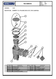
MODELS HPP040 HPP050 HPP090 HPP110 HPP140 HPP171 HPP173 HPP211 HPP213 HPP253<br />
MODELS HPHC004 HPHC005 HPHC009 HPHC011 HPHC013 HPHC017 HPHC017T HPHC021 HPHC021T HPHC025T<br />
HEAT PUMP<br />
Instruction manual<br />
BOMBA DE CALOR PARA PISCINA<br />
Manual <strong>de</strong> instrucciones<br />
POMPE À CHALEUR<br />
Manuel d´instructions<br />
WÄRMEPUMPE<br />
Bedienungsanleitung<br />
POMPA DI CALORE<br />
Manuale <strong>de</strong>lle instruzioni<br />
WARMTEPOMP<br />
Handleiding met instructies<br />
BOMBA DE CALOR<br />
Manual <strong>de</strong> instruções<br />
We reserve to change all of part of the articles or contents of this document, without prior notice.<br />
Nos reservamos el <strong>de</strong>recho <strong>de</strong> cambiar total o parcialmente las características <strong>de</strong> nuestros artículos o contenido <strong>de</strong> este documento sin previo aviso.<br />
Nous nous réservons le droit <strong>de</strong> modifier totalement oru en partie les caracteristiques <strong>de</strong> nos articles ou le contenu <strong>de</strong> ce document san pré avis.<br />
Wir behalten uns das recht vor die eigenschaften unserer produkte o<strong>de</strong>r <strong>de</strong>n inhalt diese prospektes teilweise o<strong>de</strong>r wollstanding, ohne vorherige benachichtigung su an<strong>de</strong>rn.<br />
Ci riservamo il diritto di cambiare totalemente o parzialmente le caratteristiche tecniche <strong>de</strong>i nostri prodotti ed il contenuto di questo documento senza nessum preavviso.<br />
Wij behou<strong>de</strong>n ons het recht voor geheel of ge<strong>de</strong>eltelijk <strong>de</strong> kenmerken van onze artikelen of <strong>de</strong> inhouk van <strong>de</strong>ze handleiding zon<strong>de</strong>r voorafgaand bericht te wijzigen.<br />
Reservamo-nos no <strong>de</strong>reito <strong>de</strong> alterar, total ou parcialmente as caracteristicas os nossos artigos ou o conteúdo <strong>de</strong>ste documento sem aviso prévio.<br />
V.2010-11-01 R407C R410A
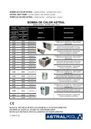
BOMBA DE CALOR BLP / BLY<br />
SERIES BLP / BLY SISTEMA AIRE/AGUA<br />
BLP / BLY HEAT PUMP - BLP / BLY SERIES AIR/WATER SYSTEM<br />
POMPE À CHALEUR BLP / BLY - SÉRIES BLP / BLY SYSTÈME AIR/EAU<br />
BLP / BLY WÄRMEPUMPE - BLP / BLY SERIE LUFT-WASSER-SYSTEM<br />
POMPA DI CALORE BLP / BLY - SERIE BLP / BLY SISTEMA ARIA/ACQUA<br />
BLP / BLY WARMETEPOMP BLP / BLY SERIES LUCHT/WATER-SYSTEEM<br />
BOMBA DE CALOR BLP / BLY - SÉRIES BLP / BLY SISTEMA AR/ÁGUAM<br />
TECHNICAL MANUAL. START-UP AND OPERATION<br />
MANUAL TÉCNICO. PUESTA EN MARCHA Y FUNCIONAMIENTO<br />
MANUEL TECHNIQUE. MISE EN ROUTE ET FONCTIONNEMENT<br />
TECHNISCHES HANDBUCH. INBETRIEBNAHME UND BETRIEBSWEISE<br />
MANUALE TECNICO. AVVIAMENTO E FUNZIONAMENTO<br />
TECHNISCHE HANDLEIDING. INGEBRUIKSTELLING EN WERKING<br />
MANUAL TÉCNICO. ARRANQUE E FUNCIONAMENTO
ENGLISH<br />
1. INTRODUCTION. . . . . . . . . . . . . . . . . . . . . . . . . . . . . . . . . . . . . . . . . . . . . . . . . . . . . . . . . . . . . . . . . . . . . . . . . .9<br />
2. ADDITIONAL RECOMMENDATIONS . . . . . . . . . . . . . . . . . . . . . . . . . . . . . . . . . . . . . . . . . . . . . . . . . . . . . . . . . 9<br />
A. Installation and maintenance . . . . . . . . . . . . . . . . . . . . . . . . . . . . . . . . . . . . . . . . . . . . . . . . . . . . . . . . . . 9<br />
B. Failures. . .. . . . . . . . . . . . . . . . . . . . . . . . . . . . . . . . . . . . . . . . . . . . . . . . . . . . . . . . . . . . . . . . . . . . . . . . . . . .10<br />
C. R407C / R410A gas. . . . . . . . . . . . . . . . . . . . . . . . . . . . . . . . . . . . . . . . . . . . . . . . . . . . . . . . . . . . . . . . . . . . .10<br />
D. Maintenance instructions . . . . . . . . . . . . . . . . . . . . . . . . . . . . . . . . . . . . . . . . . . . . . . . . . . . . . . . . . . . . . . 10<br />
3. PRECAUTIONS FOR USE AND USE CONDITIONS . . . . . . . . . . . . . . . . . . . . . . . . . . . . . . . . . . . . . . . . . . . . . 10<br />
A. Safety instructions . . . . . . . . . . . . . . . . . . . . . . . . . . . . . . . . . . . . . . . . . . . . . . . . . . . . . . . . . . . . . . . . . . .10<br />
B. Installation conditions. . . . . . . . . . . . . . . . . . . . . . . . . . . . . . . . . . . . . . . . . . . . . . . . . . . . . . . . . . . . . . . .12<br />
4. HEAT PUMP DESCRIPTION . . . . . . . . . . . . . . . . . . . . . . . . . . . . . . . . . . . . . . . . . . . . . . . . . . . . . . . . . . . . . . 12<br />
A. Technical characteristics . . . . . . . . . . . . . . . . . . . . . . . . . . . . . . . . . . . . . . . . . . . . . . . . . . . . . . . . . . . . . .12<br />
B. Description of its interior . . . . . . . . . . . . . . . . . . . . . . . . . . . . . . . . . . . . . . . . . . . . . . . . . . . . . . . . . . . . . . 13<br />
5. START-UP OF THE HEAT PUMP . . . . . . . . . . . . . . . . . . . . . . . . . . . . . . . . . . . . . . . . . . . . . . . . . . . . . . . . . . 14<br />
A. Installation rules . . . . . . . . . . . . . . . . . . . . . . . . . . . . . . . . . . . . . . . . . . . . . . . . . . . . . . . . . . . . . . . . . . . .14<br />
B. Hydraulic connections . . . . . . . . . . . . . . . . . . . . . . . . . . . . . . . . . . . . . . . . . . . . . . . . . . . . . . . . . . . . . . . .14<br />
C. Electrical connections. . . . . . . . . . . . . . . . . . . . . . . . . . . . . . . . . . . . . . . . . . . . . . . . . . . . . . . . . . . . . . . .14<br />
D. Wiring diagram of the heat pump . . . . . . . . . . . . . . . . . . . . . . . . . . . . . . . . . . . . . . . . . . . . . . . . . . . . . . . 15<br />
E. Description and operation of the controller . . . . . . . . . . . . . . . . . . . . . . . . . . . . . . . . . . . . . . . . . . . . . . . . . 16<br />
6. START-UP PROCEDURE FOR THE UNIT . . . . . . . . . . . . . . . . . . . . . . . . . . . . . . . . . . . . . . . . . . . . . . . . . . . .21<br />
7. HIBERNATION PROCEDURE . . . . . . . . . . . . . . . . . . . . . . . . . . . . . . . . . . . . . . . . . . . . . . . . . . . . . . . . . . . . .22<br />
8. GUARANTEES . . . . . . . . . . . . . . . . . . . . . . . . . . . . . . . . . . . . . . . . . . . . . . . . . . . . . . . . . . . . . . . . . . . . . . .22<br />
9. MAINTENANCE INSTRUCTIONS . . . . . . . . . . . . . . . . . . . . . . . . . . . . . . . . . . . . . . . . . . . . . . . . . . . . . . . . . . 23<br />
10. PRODUCT RECYCLING . . . . . . . . . . . . . . . . . . . . . . . . . . . . . . . . . . . . . . . . . . . . . . . . . . . . . . . . . . . . . . . .23<br />
11. WARRANTY . . . . . . . . . . . . . . . . . . . . . . . . . . . . . . . . . . . . . . . . . . . . . . . . . . . . . . . . . . . . . . . . . . . . . . . . .25<br />
ESPAÑOL<br />
1. INTRODUCCIÓN . . . . . . . . . . . . . . . . . . . . . . . . . . . . . . . . . . . . . . . . . . . . . . . . . . . . . . . . . . . . . . . . . . . . . .27<br />
2. RECOMENDACIONES COMPLEMENTARIAS . . . . . . . . . . . . . . . . . . . . . . . . . . . . . . . . . . . . . . . . . . . . . . . . . . 27<br />
A. Instalación y mantenimiento . . . . . . . . . . . . . . . . . . . . . . . . . . . . . . . . . . . . . . . . . . . . . . . . . . . . . . . . . . . 27<br />
B. Averías . . . . . . . . . . . . . . . . . . . . . . . . . . . . . . . . . . . . . . . . . . . . . . . . . . . . . . . . . . . . . . . . . . . . . . . . . . .28<br />
C. Gas R407C / R410A . . . . . . . . . . . . . . . . . . . . . . . . . . . . . . . . . . . . . . . . . . . . . . . . . . . . . . . . . . . . . . . . . . . . . .28<br />
D. Instrucciones <strong>de</strong> mantenimiento . . . . . . . . . . . . . . . . . . . . . . . . . . . . . . . . . . . . . . . . . . . . . . . . . . . . . . . . 28<br />
3. PRECAUCIONES DE EMPLEO Y CONDICIONES DE USO . . . . . . . . . . . . . . . . . . . . . . . . . . . . . . . . . . . . . . . . 28<br />
A. Instrucciones <strong>de</strong> seguridad . . . . . . . . . . . . . . . . . . . . . . . . . . . . . . . . . . . . . . . . . . . . . . . . . . . . . . . . . . . .28<br />
B. Condiciones <strong>de</strong> instalación . . . . . . . . . . . . . . . . . . . . . . . . . . . . . . . . . . . . . . . . . . . . . . . . . . . . . . . . . . . . 30<br />
4. DESCRIPCIÓN DE LA BC . . . . . . . . . . . . . . . . . . . . . . . . . . . . . . . . . . . . . . . . . . . . . . . . . . . . . . . . . . . . . . . .30<br />
A. Características técnicas . . . . . . . . . . . . . . . . . . . . . . . . . . . . . . . . . . . . . . . . . . . . . . . . . . . . . . . . . . . . . . 30<br />
B. A nivel <strong>de</strong>l interior. . . . . . . . . . . . . . . . . . . . . . . . . . . . . . . . . . . . . . . . . . . . . . . . . . . . . . . . . . . . . . . . . . . . . . . 31<br />
5. PUESTA EN MARCHA DE LA BC . . . . . . . . . . . . . . . . . . . . . . . . . . . . . . . . . . . . . . . . . . . . . . . . . . . . . . . . . .32<br />
A. Reglas <strong>de</strong> instalación . . . . . . . . . . . . . . . . . . . . . . . . . . . . . . . . . . . . . . . . . . . . . . . . . . . . . . . . . . . . . . . .32<br />
B. Conexiones hidráulicas . . . . . . . . . . . . . . . . . . . . . . . . . . . . . . . . . . . . . . . . . . . . . . . . . . . . . . . . . . . . . . .32<br />
C. Conexiones eléctricas . . . . . . . . . . . . . . . . . . . . . . . . . . . . . . . . . . . . . . . . . . . . . . . . . . . . . . . . . . . . . . . .32<br />
D. Esquema eléctrico <strong>de</strong> la BC . . . . . . . . . . . . . . . . . . . . . . . . . . . . . . . . . . . . . . . . . . . . . . . . . . . . . . . . . . . 33<br />
E. Descripción y funcionamiento <strong>de</strong>l regulador <strong>de</strong> control . . . . . . . . . . . . . . . . . . . . . . . . . . . . . . . . . . . . . . . 34<br />
6. PROCEDIMIENTO DE PUESTA EN MARCHA DE LA MÁQUINA . . . . . . . . . . . . . . . . . . . . . . . . . . . . . . . . . . . .39<br />
7. PROCEDIMIENTO DE HIBERNACIÓN . . . . . . . . . . . . . . . . . . . . . . . . . . . . . . . . . . . . . . . . . . . . . . . . . . . . . . .40<br />
8. GARANTÍAS . . . . . . . . . . . . . . . . . . . . . . . . . . . . . . . . . . . . . . . . . . . . . . . . . . . . . . . . . . . . . . . . . . . . . . . . .40<br />
9. INSTRUCCIONES DE MANTENIMIENTO . . . . . . . . . . . . . . . . . . . . . . . . . . . . . . . . . . . . . . . . . . . . . . . . . . . . 41<br />
10. RECICLAJE DEL PRODUCTO . . . . . . . . . . . . . . . . . . . . . . . . . . . . . . . . . . . . . . . . . . . . . . . . . . . . . . . . . . . . 41<br />
11. GARANTÍA . . . . . . . . . . . . . . . . . . . . . . . . . . . . . . . . . . . . . . . . . . . . . . . . . . . . . . . . . . . . . . . . . . . . . . . . . .43
FRANÇAIS<br />
1. INTRODUCTION . . . . . . . . . . . . . . . . . . . . . . . . . . . . . . . . . . . . . . . . . . . . . . . . . . . . . . . . . . . . . . . . . . . . . .45<br />
2. RECOMMANDATIONS SUPPLÉMENTAIRES . . . . . . . . . . . . . . . . . . . . . . . . . . . . . . . . . . . . . . . . . . . . . . . . . . 45<br />
A. Installation et entretien . . . . . . . . . . . . . . . . . . . . . . . . . . . . . . . . . . . . . . . . . . . . . . . . . . . . . . . . . . . . . . . 45<br />
B. Pannes . . . . . . . . . . . . . . . . . . . . . . . . . . . . . . . . . . . . . . . . . . . . . . . . . . . . . . . . . . . . . . . . . . . . . . . . . . .46<br />
C. Gaz R407C / R410A. . . . . . . . . . . . . . . . . . . . . . . . . . . . . . . . . . . . . . . . . . . . . . . . . . . . . . . . . . . . . . . . . . . .46<br />
D. Directives d’entretien .. . . . . . . . . . . . . . . . . . . . . . . . . . . . . . . . . . . . . . . . . . . . . . . . . . . . . . . . . . . . . . . 46<br />
3. PRÉCAUTIONS D’EMPLOI ET CONDITIONS D’UTILISATION . . . . . . . . . . . . . . . . . . . . . . . . . . . . . . . . . . . . . 46<br />
A. Instructions <strong>de</strong> sécurité . . . . . . . . . . . . . . . . . . . . . . . . . . . . . . . . . . . . . . . . . . . . . . . . . . . . . . . . . . . . . .46<br />
B. Conditions d’installation . . . . . . . . . . . . . . . . . . . . . . . . . . . . . . . . . . . . . . . . . . . . . . . . . . . . . . . . . . . . . 48<br />
4. DESCRIPTION DE LA POMPE À CHALEUR . . . . . . . . . . . . . . . . . . . . . . . . . . . . . . . . . . . . . . . . . . . . . . . . . . 48<br />
A. Caractéristiques techniques . . . . . . . . . . . . . . . . . . . . . . . . . . . . . . . . . . . . . . . . . . . . . . . . . . . . . . . . . . . 48<br />
B. Description <strong>de</strong>s composants internes . . . . . . . . . . . . . . . . . . . . . . . . . . . . . . . . . . . . . . . . . . . . . . . . . . . . 49<br />
5. MISE EN ROUTE DE LA POMPE À CHALEUR . . . . . . . . . . . . . . . . . . . . . . . . . . . . . . . . . . . . . . . . . . . . . . . . 50<br />
A. Normes d’installation . . . . . . . . . . . . . . . . . . . . . . . . . . . . . . . . . . . . . . . . . . . . . . . . . . . . . . . . . . . . . . . 50<br />
B. Connexions hydrauliques . . . . . . . . . . . . . . . . . . . . . . . . . . . . . . . . . . . . . . . . . . . . . . . . . . . . . . . . . . . . .50<br />
C. Connexions électriques . . . . . . . . . . . . . . . . . . . . . . . . . . . . . . . . . . . . . . . . . . . . . . . . . . . . . . . . . . . . . . .50<br />
D. Schéma <strong>de</strong> câblage <strong>de</strong> la pompe à chaleur . . . . . . . . . . . . . . . . . . . . . . . . . . . . . . . . . . . . . . . . . . . . . . . . 51<br />
E. Description et fonctionnement du régulateur . . . . . . . . . . . . . . . . . . . . . . . . . . . . . . . . . . . . . . . . . . . . . . . 52<br />
6. PROCESSUS DE MISE EN ROUTE DE LA MACHINE . . . . . . . . . . . . . . . . . . . . . . . . . . . . . . . . . . . . . . . . . . . .57<br />
7. PROCESSUS D’HIBERNATION . . . . . . . . . . . . . . . . . . . . . . . . . . . . . . . . . . . . . . . . . . . . . . . . . . . . . . . . . . . .58<br />
8. GARANTIES . . . . . . . . . . . . . . . . . . . . . . . . . . . . . . . . . . . . . . . . . . . . . . . . . . . . . . . . . . . . . . . . . . . . . . . . .58<br />
9. INSTRUCTIONS D’ENTRETIEN . . . . . . . . . . . . . . . . . . . . . . . . . . . . . . . . . . . . . . . . . . . . . . . . . . . . . . . . . . . 59<br />
10. RECYCLAGE DU PRODUIT . . . . . . . . . . . . . . . . . . . . . . . . . . . . . . . . . . . . . . . . . . . . . . . . . . . . . . . . . . . . .59<br />
11. GARANTIE . . . . . . . . . . . . . . . . . . . . . . . . . . . . . . . . . . . . . . . . . . . . . . . . . . . . . . . . . . . . . . . . . . . . . . . . . .61<br />
DEUTSCH<br />
1. EINLEITUNG . . . . . . . . . . . . . . . . . . . . . . . . . . . . . . . . . . . . . . . . . . . . . . . . . . . . . . . . . . . . . . . . . . . . . . . . .63<br />
2. ERGÄNZENDE EMPFEHLUNGEN . . . . . . . . . . . . . . . . . . . . . . . . . . . . . . . . . . . . . . . . . . . . . . . . . . . . . . . . .63<br />
A. Installation und Wartung . . . . . . . . . . . . . . . . . . . . . . . . . . . . . . . . . . . . . . . . . . . . . . . . . . . . . . . . . . . . . .63<br />
B. Störungen . . . . . . . . . . . . . . . . . . . . . . . . . . . . . . . . . . . . . . . . . . . . . . . . . . . . . . . . . . . . . . . . . . . . . . . . .64<br />
C. Gas R407C / R410A . . . . . . . . . . . . . . . . . . . . . . . . . . . . . . . . . . . . . . . . . . . . . . . . . . . . . . . . . . . . . . . . . . .64<br />
D. Wartungsanweisung . . . . . . . . . . . . . . . . . . . . . . . . . . . . . . . . . . . . . . . . . . . . . . . . . . . . . . . . . . . . . . . . .64<br />
3. EINSATZWARNUNGEN UND BETRIEBSBEDINGUNGEN . . . . . . . . . . . . . . . . . . . . . . . . . . . . . . . . . . . . . . . . 64<br />
A. Sicherheitsanweisungen . . . . . . . . . . . . . . . . . . . . . . . . . . . . . . . . . . . . . . . . . . . . . . . . . . . . . . . . . . . . . .64<br />
B. Installationsbedingungen . . . . . . . . . . . . . . . . . . . . . . . . . . . . . . . . . . . . . . . . . . . . . . . . . . . . . . . . . . . . .66<br />
4. BESCHREIBUNG DER WÄRMEPUMPE . . . . . . . . . . . . . . . . . . . . . . . . . . . . . . . . . . . . . . . . . . . . . . . . . . . . . 66<br />
A. Technische Daten . . . . . . . . . . . . . . . . . . . . . . . . . . . . . . . . . . . . . . . . . . . . . . . . . . . . . . . . . . . . . . . . . . .66<br />
B. Innenaufbau . . . . . . . . . . . . . . . . . . . . . . . . . . . . . . . . . . . . . . . . . . . . . . . . . . . . . . . . . . . . . . . . . . . . . . .67<br />
5. INBETRIEBNAHME DER WÄRMEPUMPE . . . . . . . . . . . . . . . . . . . . . . . . . . . . . . . . . . . . . . . . . . . . . . . . . . . 68<br />
A. Installationsregeln . . . . . . . . . . . . . . . . . . . . . . . . . . . . . . . . . . . . . . . . . . . . . . . . . . . . . . . . . . . . . . . . . . .68<br />
B. Hydraulische Anschlüsse . . . . . . . . . . . . . . . . . . . . . . . . . . . . . . . . . . . . . . . . . . . . . . . . . . . . . . . . . . . . .68<br />
C. Elektrische Anschlüsse . . . . . . . . . . . . . . . . . . . . . . . . . . . . . . . . . . . . . . . . . . . . . . . . . . . . . . . . . . . . . . .68<br />
D. Elektrisches Schaltbild <strong>de</strong>r Wärmepumpe . . . . . . . . . . . . . . . . . . . . . . . . . . . . . . . . . . . . . . . . . . . . . . . . . 69<br />
E. Beschreibung und Betriebsweise <strong>de</strong>s Reglers . . . . . . . . . . . . . . . . . . . . . . . . . . . . . . . . . . . . . . . . . . . . . . 70<br />
6. VERFAHREN ZUR INBETRIEBNAHME DES GERÄTS . . . . . . . . . . . . . . . . . . . . . . . . . . . . . . . . . . . . . . . . . . .75<br />
7. VERFAHREN ZUR ABSCHALTUNG UND VORBEREITUNG AUF DEN WINTER . . . . . . . . . . . . . . . . . . . . . . . .76<br />
8. GARANTIE . . . . . . . . . . . . . . . . . . . . . . . . . . . . . . . . . . . . . . . . . . . . . . . . . . . . . . . . . . . . . . . . . . . . . . . . . .76<br />
9. WARTUNGSANWEISUNGEN . . . . . . . . . . . . . . . . . . . . . . . . . . . . . . . . . . . . . . . . . . . . . . . . . . . . . . . . . . . . . 77<br />
10. PRODUKTENTSORGUNG . . . . . . . . . . . . . . . . . . . . . . . . . . . . . . . . . . . . . . . . . . . . . . . . . . . . . . . . . . . . . .77<br />
11. GARANTIE . . . . . . . . . . . . . . . . . . . . . . . . . . . . . . . . . . . . . . . . . . . . . . . . . . . . . . . . . . . . . . . . . . . . . . . . . .79
ITALIANO<br />
1. INTRODUZIONE . . . . . . . . . . . . . . . . . . . . . . . . . . . . . . . . . . . . . . . . . . . . . . . . . . . . . . . . . . . . . . . . . . . . . .81<br />
2. RACCOMANDAZIONI AGGIUNTIVE . . . . . . . . . . . . . . . . . . . . . . . . . . . . . . . . . . . . . . . . . . . . . . . . . . . . . . . . 81<br />
A. Installazione e manutenzione . . . . . . . . . . . . . . . . . . . . . . . . . . . . . . . . . . . . . . . . . . . . . . . . . . . . . . . . . 81<br />
B. Avarie . . . . . . . . . . . . . . . . . . . . . . . . . . . . . . . . . . . . . . . . . . . . . . . . . . . . . . . . . . . . . . . . . . . . . . . . . . . .82<br />
C. Gas R407C / R410A . . . . . . . . . . . . . . . . . . . . . . . . . . . . . . . . . . . . . . . . . . . . . . . . . . . . . . . . . . . . . . . . . . . .82<br />
D. Istruzioni di manutenzione . . . . . . . . . . . . . . . . . . . . . . . . . . . . . . . . . . . . . . . . . . . . . . . . . . . . . . . . . . . .82<br />
3. PRECAUZIONI DI IMPIEGO E CONDIZIONI DI USO . . . . . . . . . . . . . . . . . . . . . . . . . . . . . . . . . . . . . . . . . . . . 82<br />
A. Istruzioni di sicurezza . . . . . . . . . . . . . . . . . . . . . . . . . . . . . . . . . . . . . . . . . . . . . . . . . . . . . . . . . . . . . . . . 82<br />
B. Condizioni di installazione . . . . . . . . . . . . . . . . . . . . . . . . . . . . . . . . . . . . . . . . . . . . . . . . . . . . . . . . . . . . . 84<br />
4. DESCRIZIONE DELLA PC . . . . . . . . . . . . . . . . . . . . . . . . . . . . . . . . . . . . . . . . . . . . . . . . . . . . . . . . . . . . . . . .84<br />
A. Caratteristiche tecniche . . . . . . . . . . . . . . . . . . . . . . . . . . . . . . . . . . . . . . . . . . . . . . . . . . . . . . . . . . . . . . 84<br />
B. Parte interna . . . . . . . . . . . . . . . . . . . . . . . . . . . . . . . . . . . . . . . . . . . . . . . . . . . . . . . . . . . . . . . . . . . . . . .85<br />
5. AVVIAMENTO DELLA PC . . . . . . . . . . . . . . . . . . . . . . . . . . . . . . . . . . . . . . . . . . . . . . . . . . . . . . . . . . . . . . . .86<br />
A. Regole di installazione . . . . . . . . . . . . . . . . . . . . . . . . . . . . . . . . . . . . . . . . . . . . . . . . . . . . . . . . . . . . . . .86<br />
B. Connessioni idrauliche . . . . . . . . . . . . . . . . . . . . . . . . . . . . . . . . . . . . . . . . . . . . . . . . . . . . . . . . . . . . . . .86<br />
C. Connessioni elettriche . . . . . . . . . . . . . . . . . . . . . . . . . . . . . . . . . . . . . . . . . . . . . . . . . . . . . . . . . . . . . . . .86<br />
D. Schema elettrico <strong>de</strong>lla PC . . . . . . . . . . . . . . . . . . . . . . . . . . . . . . . . . . . . . . . . . . . . . . . . . . . . . . . . . . . . .87<br />
E. Descrizione e funzionamento <strong>de</strong>l regolatore di controllo . . . . . . . . . . . . . . . . . . . . . . . . . . . . . . . . . . . . . . . 88<br />
6. PROCEDURA DI AVVIAMENTO DELLA MACCHINA . . . . . . . . . . . . . . . . . . . . . . . . . . . . . . . . . . . . . . . . . . . . .93<br />
7. PROCEDURA DI SPEGNIMENTO . . . . . . . . . . . . . . . . . . . . . . . . . . . . . . . . . . . . . . . . . . . . . . . . . . . . . . . . . .94<br />
8. GARANZIE . . . . . . . . . . . . . . . . . . . . . . . . . . . . . . . . . . . . . . . . . . . . . . . . . . . . . . . . . . . . . . . . . . . . . . . . . .94<br />
9. ISTRUZIONI DI MANUTENZIONE . . . . . . . . . . . . . . . . . . . . . . . . . . . . . . . . . . . . . . . . . . . . . . . . . . . . . . . . . 95<br />
10. RICICLAGGIO DEL PRODOTTO . . . . . . . . . . . . . . . . . . . . . . . . . . . . . . . . . . . . . . . . . . . . . . . . . . . . . . . . . . 95<br />
11. GARANZIA . . . . . . . . . . . . . . . . . . . . . . . . . . . . . . . . . . . . . . . . . . . . . . . . . . . . . . . . . . . . . . . . . . . . . . . . . .97<br />
NEDERLANDS<br />
1. INLEIDING. . . . . . . . . . . . . . . . . . . . . . . . . . . . . . . . . . . . . . . . . . . . . . . . . . . . . . . . . . . . . . . . . . . . . . . . . . .99<br />
2. BIJKOMENDE AANBEVELINGEN . . . . . . . . . . . . . . . . . . . . . . . . . . . . . . . . . . . . . . . . . . . . . . . . . . . . . . . . . . 99<br />
A. Installatie en on<strong>de</strong>rhoud . . . . . . . . . . . . . . . . . . . . . . . . . . . . . . . . . . . . . . . . . . . . . . . . . . . . . . . . . . . . . .99<br />
B. Storingen . . . . . . . . . . . . . . . . . . . . . . . . . . . . . . . . . . . . . . . . . . . . . . . . . . . . . . . . . . . . . . . . . . . . . . . .100<br />
C. Gas R407C / R410A. . . . . . . . . . . . . . . . . . . . . . . . . . . . . . . . . . . . . . . . . . . . . . . . . . . . . . . . . . . . . . . . . .100<br />
D. Instructies voor het on<strong>de</strong>rhoud . . . . . . . . . . . . . . . . . . . . . . . . . . . . . . . . . . . . . . . . . . . . . . . . . . . . . . . .100<br />
3. VOORZORGEN BIJ HET GEBRUIK EN GEBRUIKSVOORWAARDEN . . . . . . . . . . . . . . . . . . . . . . . . . . . . . . . 100<br />
A. Veiligheidsinstructies . . . . . . . . . . . . . . . . . . . . . . . . . . . . . . . . . . . . . . . . . . . . . . . . . . . . . . . . . . . . . . . . 100<br />
B. Installatievoorwaar<strong>de</strong>n . . . . . . . . . . . . . . . . . . . . . . . . . . . . . . . . . . . . . . . . . . . . . . . . . . . . . . . . . . . . .102<br />
4. BESCHRIJVING VAN DE WP . . . . . . . . . . . . . . . . . . . . . . . . . . . . . . . . . . . . . . . . . . . . . . . . . . . . . . . . . . . .102<br />
A. Technische kenmerken . . . . . . . . . . . . . . . . . . . . . . . . . . . . . . . . . . . . . . . . . . . . . . . . . . . . . . . . . . . . . .102<br />
B. Binnenin . . . . . . . . . . . . . . . . . . . . . . . . . . . . . . . . . . . . . . . . . . . . . . . . . . . . . . . . . . . . . . . . . . . . . . . . .103<br />
5. INBEDRIJFSTELLING VAN DE WP . . . . . . . . . . . . . . . . . . . . . . . . . . . . . . . . . . . . . . . . . . . . . . . . . . . . . . . . 104<br />
A. Regels voor <strong>de</strong> installatie . . . .. . . . . . . . . . . . . . . . . . . . . . . . . . . . . . . . . . . . . . . . . . . . . . . . . . . . . . . . 104<br />
B. Hydraulische aansluitingen. . . . . . . . . . . . . . . . . . . . . . . . . . . . . . . . . . . . . . . . . . . . . . . . . . . . . . . . . . . . . .104<br />
C. Elektrische aansluitingen . . . . . . . . . . . . . . . . . . . . . . . . . . . . . . . . . . . . . . . . . . . . . . . . . . . . . . . . . . . . 104<br />
D. Elektrisch schema van <strong>de</strong> WP . . . . . . . . . . . . . . . . . . . . . . . . . . . . . . . . . . . . . . . . . . . . . . . . . . . . . . . . 105<br />
E. Beschrijving en werking van <strong>de</strong> controleregelaar . . . . . . . . . . . . . . . . . . . . . . . . . . . . . . . . . . . . . . . . . . . 106<br />
6. PROCEDURE VOOR DE INBEDRIJFSTELLING VAN DE MACHINE . . . . . . . . . . . . . . . . . . . . . . . . . . . . . . . . .111<br />
7. PROCEDURE VOOR HET WINTERONDERHOUD . . . . . . . . . . . . . . . . . . . . . . . . . . . . . . . . . . . . . . . . . . . . .112<br />
8. GARANTIES . . . . . . . . . . . . . . . . . . . . . . . . . . . . . . . . . . . . . . . . . . . . . . . . . . . . . . . . . . . . . . . . . . . . . . . .112<br />
9. INSTRUCTIES VOOR HET ONDERHOUD . . . . . . . . . . . . . . . . . . . . . . . . . . . . . . . . . . . . . . . . . . . . . . . . . . . 113<br />
10. RECYCLAGE VAN HET PRODUCT . . . . . . . . . . . . . . . . . . . . . . . . . . . . . . . . . . . . . . . . . . . . . . . . . . . . . . .113<br />
11. GARANTIE . . . . . . . . . . . . . . . . . . . . . . . . . . . . . . . . . . . . . . . . . . . . . . . . . . . . . . . . . . . . . . . . . . . . . . . .115
PORTUGUÊS<br />
1. INTRODUÇÃO. . . . . . . . . . . . . . . . . . . . . . . . . . . . . . . . . . . . . . . . . . . . . . . . . . . . . . . . . . . . . . . . . . . . . . .117<br />
2. RECOMENDAÇÕES COMPLEMENTARES . . . . . . . . . . . . . . . . . . . . . . . . . . . . . . . . . . . . . . . . . . . . . . . . . .117<br />
A. Instalação e manutenção . . . . . . . . . . . . . . . . . . . . . . . . . . . . . . . . . . . . . . . . . . . . . . . . . . . . . . . . . . . .117<br />
B. Avarias . . . . . . . . . . . . . . . . . . . . . . . . . . . . . . . . . . . . . . . . . . . . . . . . . . . . . . . . . . . . . . . . . . . . . . . . . .118<br />
C. Gás R407C / R410A. . . . . . . . . . . . . . . . . . . . . . . . . . . . . . . . . . . . . . . . . . . . . . . . . . . . . . . . . . . . . . . . . .118<br />
D. Instruções <strong>de</strong> manutenção . . . . . . . . . . . . . . . . . . . . . . . . . . . . . . . . . . . . . . . . . . . . . . . . . . . . . . . . . . .118<br />
3. PRECAUÇÕES DE EMPREGO E CONDIÇÕES DE USO . . . . . . . . . . . . . . . . . . . . . . . . . . . . . . . . . . . . . . . . . 118<br />
A. Instruções <strong>de</strong> segurança . . . . . . . . . . . . . . . . . . . . . . . . . . . . . . . . . . . . . . . . . . . . . . . . . . . . . . . . . . . . .118<br />
B. Condições <strong>de</strong> instalação . . . . . . . . . . . . . . . . . . . . . . . . . . . . . . . . . . . . . . . . . . . . . . . . . . . . . . . . . . . . .120<br />
4. DESCRIÇÃO DA BC . . . . . . . . . . . . . . . . . . . . . . . . . . . . . . . . . . . . . . . . . . . . . . . . . . . . . . . . . . . . . . . . . . .120<br />
A. Características técnicas . . . . . . . . . . . . . . . . . . . . . . . . . . . . . . . . . . . . . . . . . . . . . . . . . . . . . . . . . . . . .120<br />
B. A nível do interior . . . . . . . . . . . . . . . . . . . . . . . . . . . . . . . . . . . . . . . . . . . . . . . . . . . . . . . . . . . . . . . . . .121<br />
5. ARRANQUE DA BC . . . . . . . . . . . . . . . . . . . . . . . . . . . . . . . . . . . . . . . . . . . . . . . . . . . . . . . . . . . . . . . . . . .122<br />
A. Regras <strong>de</strong> instalação . . . . . . . . . . . . . . . . . . . . . . . . . . . . . . . . . . . . . . . . . . . . . . . . . . . . . . . . . . . . . . . .122<br />
B. Ligações hidráulicas . . . . . . . . . . . . . . . . . . . . . . . . . . . . . . . . . . . . . . . . . . . . . . . . . . . . . . . . . . . . . . . .122<br />
C. Ligações eléctricas . . . . . . . . . . . . . . . . . . . . . . . . . . . . . . . . . . . . . . . . . . . . . . . . . . . . . . . . . . . . . . . . .122<br />
D. Esquema eléctrico da BC . . . . . . . . . . . . . . . . . . . . . . . . . . . . . . . . . . . . . . . . . . . . . . . . . . . . . . . . . . . . 123<br />
E. Descrição e funcionamento do regulador <strong>de</strong> controlo . . . . . . . . . . . . . . . . . . . . . . . . . . . . . . . . . . . . . . . . 124<br />
6. PROCEDIMENTO DE ARRANQUE DA MÁQUINA . . . . . . . . . . . . . . . . . . . . . . . . . . . . . . . . . . . . . . . . . . . . .129<br />
7. PROCEDIMENTO DE HIBERNAÇÃO . . . . . . . . . . . . . . . . . . . . . . . . . . . . . . . . . . . . . . . . . . . . . . . . . . . . . . .130<br />
8. GARANTIA . . . . . . . . . . . . . . . . . . . . . . . . . . . . . . . . . . . . . . . . . . . . . . . . . . . . . . . . . . . . . . . . . . . . . . . . . .130<br />
9. INSTRUÇÕES DE MANUTENÇÃO . . . . . . . . . . . . . . . . . . . . . . . . . . . . . . . . . . . . . . . . . . . . . . . . . . . . . . . . 131<br />
10. RECICLAGEM DO PRODUTO . . . . . . . . . . . . . . . . . . . . . . . . . . . . . . . . . . . . . . . . . . . . . . . . . . . . . . . . . . .131<br />
11. GARANTIA . . . . . . . . . . . . . . . . . . . . . . . . . . . . . . . . . . . . . . . . . . . . . . . . . . . . . . . . . . . . . . . . . . . . . . . . .133
TECHNICAL MANUAL. START-UP AND OPERATION<br />
8 ESSENTIAL POINTS. (Read carefully before start-up)<br />
1.<br />
Check unit condition upon receipt. If the unit is damaged or if the shipment is not complete, make a note in<br />
the <strong>de</strong>livery note and send an immediate complaint to the company that forwar<strong>de</strong>d the shipment.<br />
2.<br />
It is essential that the installer receives the installation manual. Read the manual and follow the safety, use<br />
and handling instructions of the product carefully. Keep the manual for further reference.<br />
3.<br />
When washing the purification filter, the heat pump must be off. In the event of any maintenance or repair<br />
manipulation in the heat pump, it is obligatory to switch off the power supply. You should not try any kind of<br />
repair work in the heat pump. A qualified installer should be called. He will take it upon himself to return the<br />
faulty unit to the manufacturer. In or<strong>de</strong>r to guarantee the correct operation of the pump it is necessary to<br />
make a periodic maintenance of the pump, to make a good use of the pump and not to exceed the limits set<br />
by the manufacturer.<br />
4.<br />
The installation must be ma<strong>de</strong> by qualified technical personnel. These personnel commit themselves to<br />
observe the instructions of the manufacturer and the applicable regulations. They also must have available<br />
standard issue material and must guarantee their training in refrigeration facilities. The manufacturer should<br />
not be responsible for any damage in the installation that may cause damages to animals, objects or<br />
people. The manufacturer should not be responsible either for any wrong manipulations by the installer.<br />
5.<br />
This heat pump should be used for the purposes it has been built for. Any other use which does not conform<br />
will be consi<strong>de</strong>red dangerous. The safety in the operation of the heat pump could be compromised by the<br />
lack of observance of the previous points. The damages caused by errors in the installation, use or due to<br />
the lack of observance of the instructions or applicable regulations are exclu<strong>de</strong>d from any guarantee.<br />
6.<br />
In the case of sale to third parties, it is advisable to inclu<strong>de</strong> this manual with the heat pump, in case the new<br />
client or installer wishes to consult it.<br />
7.<br />
The machine can take of 2 to 3 days in warming up the water until the wished temperature <strong>de</strong>pending on<br />
the initial conditions.<br />
8.<br />
The machine must work with filter.
BLP / BLY HEAT PUMP<br />
english<br />
1. INTRODUCTION<br />
Thank you for acquiring the heat pump for heating outdoor swimming pools. The experience our company has gained during more<br />
than 20 years in the world of air conditioning of swimming pools has been put to your service in this product, in which we also incorporate<br />
the technical breakthroughs that turn this heat pump into the equipment that can solve once and for all the air conditioning<br />
of your swimming pool, extending thus the length of your bathing season.<br />
IMPORTANT<br />
We kindly request the client or installer to read this manual carefully in or<strong>de</strong>r to:<br />
Complete a correct installation and start-up.<br />
Be familiar with all the potentialities of the unit and to take into account all the necessary circumstances for<br />
its correct and lasting operation.<br />
Dealer’s stamp<br />
Installer’s stamp<br />
2. ADDITIONAL RECOMMENDATIONS. Pressure Equipment Directive (PED-97/23/EC)<br />
A. Installation and maintenance<br />
- In the event of any intervention in the unit, installation, start-up or maintenance, the personnel in charge of these operations must<br />
be familiar with both the instructions and recommendations contained in the installation manual and the elements of the project. -<br />
The personnel in charge of the receipt of the unit will perform a visual inspection in or<strong>de</strong>r to verify the possible damages suffered in<br />
the transport: refrigeration circuit, electrical cabinet, frame and housing.<br />
- It is prohibited to place the unit near:<br />
Heat sources Flammable materials Building air intakes<br />
- The unit must be installed, started-up, repaired and maintained by qualified personnel according to applicable regulations and<br />
laws.<br />
- During installation, repairs and maintenance piping should not be tread on or used as a support, otherwise the piping could break<br />
and the R407C/R410A gas could cause severe burns.<br />
- During maintenance of the unit, the composition and state of the gas will be revised as well as possible oil stains (leaks in the<br />
refrigeration circuit).<br />
- During the annual maintenance revision of circuit water tightness according to regulations, verify that the high-pressure and lowpressure<br />
controllers are properly connected to the refrigeration circuit and that they switch off the electrical circuit in case of failure.<br />
- In the event of any manipulation or intervention on the refrigeration circuit, it is obligatory to switch off the unit and wait several<br />
minutes before puncturing pressure gauges or measuring temperatures. Some elements such as the compressor and pipes can<br />
reach high temperatures and high pressures that can lead to important burns.<br />
9
TECHNICAL MANUAL. START-UP AND OPERATION<br />
B. Failures<br />
- Any intervention in the refrigeration circuit must be ma<strong>de</strong> following the applicable safety regulations: recovery of refrigeration fluids,<br />
nitrogen welds, etc.<br />
- Any welding intervention must be ma<strong>de</strong> by qualified wel<strong>de</strong>rs.<br />
- For units loa<strong>de</strong>d with R407C/R410A, refer to specific instructions in the user manual.<br />
- Piping can only be replaced by copper pipes according to standard NF EN 12735-I.<br />
- Search for leaks:<br />
a. Never use oxygen or dry air, danger of fire or explosion.<br />
b. Use dry nitrogen or the mixture of nitrogen and coolant indicated in the plate. - Any substitution of parts different<br />
to the ones consi<strong>de</strong>red by the manufacturer, any modifications in the refrigeration circuit, any substitution of refrigeration fluid by a<br />
fluid different to the one indicated in the plate or any use of the unit beyond the limits specified in the unit documentation<br />
would result in the cancellation of the guarantee. - All information must be registered in the unit manual that must be inclu<strong>de</strong>d<br />
in the installation project.<br />
C. R407C / R410A Gas<br />
- The R407C / R410A liquid, unlike the R22, is not a pure liquid, but a compound mixed. The compressors approved to work with<br />
this liquid are specific and are preloa<strong>de</strong>d with polyol ester oil.<br />
- This oil, unlike mineral oil, is very hygroscopic and it very quickly absorbs the ambient air humidity, something that can strongly<br />
alter its lubricating abilities and lead in due time to the <strong>de</strong>struction of the compressor.<br />
D. Maintenance instructions<br />
- Never add oil to the unit; the compressor is loa<strong>de</strong>d with specific oil, polyol ester (POE) that does not tolerate the presence of other<br />
types of oil.<br />
- The instruments used for the load, pressure measurement, creation of a vacuum and recovery of the liquid must be compatible<br />
and be only used for the R407C / R410A liquid.<br />
- The weight of the coolant contained in the storage <strong>de</strong>posit must be constantly verified. If the remaining weight is lower than 10%<br />
of the gross weight, do not use it.<br />
- In the event of a new charge:<br />
· Do not use the load cylin<strong>de</strong>r<br />
· Use a balance and a bottle of R407C / R410A with an immersion tube<br />
· Load the weight of R407C / R410A following the value indicated in the plate where the characteristics of the unit are<br />
specified. - The load must be done in liquid phase.<br />
- In case of leaks, do not complete the load: recover the remaining liquid for its recycling and carry out a full load again. The reco<br />
very, recycling or <strong>de</strong>struction of liquid should always be carried out in accordance with the applicable laws in each country.<br />
- If the refrigeration circuit is open, the following tasks must be carried out:<br />
· Minimize the entrance of ambient air in the circuit<br />
· Replace the <strong>de</strong>hydrator.<br />
· Carry out the creation of a vacuum to a minimum level of 0.3 mbar (static).<br />
3. PRECAUTIONS FOR USE AND CONDITIONS OF USE<br />
A. Safety instructions<br />
Read the safety instructions prior to any manipulation:<br />
ATTENTION<br />
Any incorrect manipulation may cause an important risk that could involve <strong>de</strong>adly injuries.<br />
WARNING<br />
Any incorrect manipulation may cause serious damages to the user and the unit.<br />
10
BLP / BLY HEAT PUMP<br />
english<br />
ATTENTION
TECHNICAL MANUAL. START-UP AND OPERATION<br />
B. Installation conditions<br />
Do not install the unit near a flammable gas source, since a gas leak may occur and cause an explosion.<br />
WARNING<br />
SPECIFIC INSTRUCTIONS: It is obligatory for users contact a specialized company that has experience installing and repairing<br />
heat pumps. Users should not install or repair the heat pump themselves nor should another person do it.<br />
The operating environment of the unit usually varies between 10 ºC and 35 ºC.<br />
4. DESCRIPTION OF THE HEAT PUMP<br />
A. Technical characteristics<br />
- The calculation of power has been done with an outdoor air temperature<br />
of 14 ºC, a water temperature of 24 ºC and 70% humidity.<br />
- Operational temperature limits:<br />
· Outdoor minimum air temperature: 5°C<br />
· Maximum temperature of pool water: 36°C<br />
·<br />
- Maximum inlet water pressure 3,5 bar.<br />
12
english<br />
BLP / BLY HEAT PUMP<br />
MODEL<br />
(1) HPP040 HPP050 HPP090 HPP110 HPP140 HPP171 HPP173 HPP211 HPP213 HPP253 HPP313<br />
(2) HPHC004 HPHC005 HPHC009 HPHC011 HPHC013 HPHC017 HPHC017T HPHC021 HPHC021T HPHC025T HPHC031T<br />
DATA CV 1/2HP 1HP 2HP 2,5HP 3HP 4HP 4HP 5HP 5HP 6HP 6HP<br />
POWER OUTPUT<br />
BTU/H 10200 14000 29000 34000 45000 58000 58000 72000 72000 85000 105000<br />
W 3000 4200 8500 11500 13500 17000 17000 21000 21000 25000 31000<br />
POWER INPUT W 600 850 1700 2300 2300 3500 3500 4500 4500 5500 6500<br />
EFFICIENCY COP 5,0 5,0 5,0 5,0 5,0 4,9 4,9 4,7 4,7 4,55 4,75<br />
NOMINAL CURRENT A 2,8 4,1 8,3 9,2 12,0 16,0 6,0 21 7,8 9,6 10,2<br />
VOLTAGE / FREQUENCY V/Ph/Hz 230/1/50 230/1/50 230/1/50 230/1/50 230/1/50 230/1/50 380/3/50 230/1/50 380/3/50 380/3/50 380/3/50<br />
COMPRESSOR TYPE 1 unit ROTARY ROTARY ROTARY ROTARY ROTARY SCROLL SCROLL SCROLL SCROLL SCROLL SCROLL<br />
HEAT EXCHANGER TITANIUM<br />
REFRIGERANT (kg)<br />
(1) R410A 0,45 0,70 1,25 1,4 1,55 2,2 2,2 2,75 2,75 3,25 3,45<br />
(2) R407C 0,5 0,75 1,3 1,45 1,6 2,25 2,25 2,8 2,8 3,3 3,5<br />
FAN POWER INPUT W 1x15 1x20 1x45 1X95 1x95 1x120 1x120 1x200 1x200 1x200 1x200<br />
FAN ROTATE SPEED RPM 850 850 850 850 850 850 850 850 850 850 850<br />
NOISE LEVEL dB 47 47 51 55 58 58 58 58 58 58 58<br />
WATER CONNECTION mm 50 50 50 50 50 50 50 50 50 50 50<br />
WATER FLOW m3/h 4,0 4,0 5,0 6,0 7,5 7,5 7,5 9,0 9,0 9,0 9,0<br />
WATER PRESSURE LOSS kPa 10 10 10 12 12 12 12 12 12 12 12<br />
MODEL<br />
(1) (2) (1) (2) (1) (2) (1) (2) (1) (2) (1) (2) (1) (2) (1) (2) (1) (2) (1) (2) (1) (2)<br />
NET DIMENSION<br />
LENGTH 91 73,5 91 73,5 91 91 91 91 91 91 110 110 110 110 110 110 110 110 110 110 110 110<br />
cm<br />
WIDTH 36 34,5 36 34,5 36 38 36 38 36 38 46 48 46 48 46 48 46 48 46 48 46 48<br />
HEIGHT 65 50 65 50 65 65 65 65 65 65 95 95 95 95 95 95 95 95 95 95 95 95<br />
WEIGHT NET Kg 34 38 70 75 75 97 97 110 110 115 118<br />
B. Description of its interior<br />
Evaporator<br />
Circuit board<br />
Fan engine<br />
Connection<br />
terminals<br />
Temperature<br />
probe<br />
Titanium<br />
con<strong>de</strong>nser<br />
Compressor<br />
13
TECHNICAL MANUAL. START-UP AND OPERATION<br />
5. START-UP OF THE HEAT PUMP<br />
A. Installation rules<br />
It is necessary to <strong>de</strong>termine the unit location according to certain criteria:<br />
· The unit must be secured on a hard base (concrete or hard steel frame type) and must be protected from flood risks.<br />
· The unit must be installed outsi<strong>de</strong>, far away from the sun’s direct rays and any other heat source.<br />
· A clear space around the unit of around 1 m at the front and a minimum of 0.5 m at the back and si<strong>de</strong>s of the unit must<br />
be left.<br />
· The air caused by the helix must be directed away from the limits of the work environment (windows, doors...).<br />
· The minimum distance between the heat pump and the rim of the swimming pool must be, at least, 3.5 m.<br />
(Electrotechnic Regulations for Low Voltage, Supplementary Technical Instructions, Low Voltage, 31, ITC-BT-31).<br />
· The electrical and hydraulic connections must be ma<strong>de</strong> according to the applicable regulations (NF C 15 100, EC 1364).<br />
The ducting for the connections must be fixed.<br />
B. Hydraulic connections<br />
Connect the PVC 50/38 piping water inlets and outlets of the swimming pool to the heat pump inlet and outlet. The connection will<br />
be performed through a by-pass over the filtering circuit of the swimming pool after the filter and before the water treatment.<br />
The unit is provi<strong>de</strong>d with two D-50 PVC unions, two 50-40x1 1/2” PVC adaptor nipples and two NPT 1 1/2”-38 hose couplings. For<br />
those setups fitted with D-50 pipes, it should be enough installing the unions (photo 1). For those setups fitted with D-38 pipes, the<br />
adaptor nipples and D-38 hose couplings must be installed (photos 2 and 3)<br />
PVC D-50 unions<br />
NPT D-1/2”-38 hose couplings<br />
50-40 x 1 1/2’ adaptor nipple<br />
photo 1 photo 2 photo 3<br />
Once the necessary fittings are installed, inlets and outlets are connected.<br />
C. Electrical connection<br />
14<br />
· The power supply for the heat pump must come, prefera<strong>bly</strong>, from a sole circuit provi<strong>de</strong>d with standard-issue protection<br />
components (see above: protection by a 30 mA differential) and a magnetic circuit breaker.<br />
· The electrical installation must be carried out by a qualified professional (an electrician, for example) according to the<br />
applicable laws and regulations of the target country.<br />
· The heat pump circuit must be linked to a safety earth circuit levelled to the terminal block .<br />
· The cables must be correctly installed so that they do not cause interferences (items in the lead boards).<br />
· The heat pump may be connected to an earthed general-purpose power supply.<br />
· Cable section: This section is indicative and must be verified and adapted according to the installation needs and
BLP / BLY HEAT PUMP<br />
english<br />
conditions.<br />
· The acceptable tolerance to voltage fluctuation is +/- 10% during operation.<br />
MODEL<br />
VOLTAGE / FREQUENCY<br />
(V/Ph/Hz)<br />
HPP040 HPP050 HPP090 HPP110 HPP140 HPP171 HPP173 HPP211 HPP213 HPP253 HPP313<br />
HPHC004 HPHC005 HPHC009 HPHC011 HPHC013 HPHC017 HPHC017T HPHC021 HPHC021T HPHC025T HPHC031T<br />
230/1/50 230/1/50 230/1/50 230/1/50 230/1/50 230/1/50 380/3/50 230/1/50 380/3/50 380/3/50 380/3/50<br />
SHORT CIRCUIT<br />
PROTECTION<br />
DEVICE<br />
NOMINAL<br />
CURRENT<br />
RESIDUAL<br />
CURRENT<br />
LIMIT<br />
2,5 A 3,8 A 8,3 A 9,2 A 12,0 A 16,0 A 6,0 A 21 A 7,8 A 9,6 A 10,2 A<br />
20mA 25mA 30mA 35mA 45 mA 60 mA 25 mA<br />
100<br />
mA<br />
35 mA 40 mA 45 mA<br />
FUSE GAUGE 16 A 16 A 20 A 32 A 32 A 40 A 20 A 60 A 20 A 20 A 25 A<br />
SUPPLY GAUGE 3 x 1,0 3 x 1,0 3 x 2,5 3 x 2,5 3 x 2,5 3 x 4 5 x 2,5 3 x 4 5 x 2,5 5 x 2,5 5 x 2,5<br />
15
TECHNICAL MANUAL. START-UP AND OPERATION<br />
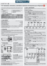
E. Description and operation of the controller<br />
NA6888 User Gui<strong>de</strong><br />
Main Function and Technique In<strong>de</strong>x<br />
Main Function: the controller is the special controller for heat pump water heater, it contains 2 temperature sensors (water temperature,<br />
outdoor temperature), 2 control outputs (compressor, <strong>de</strong>frost) and one alarm signal input (used for high and low pressure<br />
protection). Its main function is showing below<br />
Temperature Display and Controlling: it can display water tank temperature and outdoor temperature, and control the temperature<br />
in water tank between the temperature upper and lower limit.<br />
Auto Defrost Controlling: it has <strong>de</strong>frosting controlling logic of heat pump optimization <strong>de</strong>sign, and can <strong>de</strong>frost effectively in or<strong>de</strong>r<br />
to ensure that the outdoor machine can run normally at low temperature, you can set several kinds of <strong>de</strong>frost way: four-way valve<br />
<strong>de</strong>frost, bypass valve <strong>de</strong>frost or electric heat <strong>de</strong>frost.<br />
External alarm: one outsi<strong>de</strong> alarm input, it can be set to 5 mo<strong>de</strong>s: always open, always open locked, always closed, always closed<br />
locked or forbid<strong>de</strong>n.<br />
Others: temperature upper and lower limit can be set, direction of four-way valve can be set, compressor start <strong>de</strong>lay protection,<br />
temperature sensor error alarm and so on.<br />
Main Technique In<strong>de</strong>x:<br />
- Temperature display range: -50/150°C (the step is 0.1°C) - Temperature setting<br />
range: -45/145°C (the step is 0.1°C) - Power supply: AC 220V±10% or AC<br />
380V±10% 50Hz (refer to the wiring diagram)<br />
- Operating environment: temperature -20Cº/50Cº, humidity
The function of the LED on the panel is showing below:<br />
What’s the meaning of the in<strong>de</strong>x lights on the panel?<br />
BLP / BLY HEAT PUMP<br />
english<br />
In<strong>de</strong>x Light Name Light Flash<br />
Temp Setting In the state of temp setting -<br />
Refrigeration<br />
Refrigerating<br />
Ready to refrigerate, in the state of compressor start <strong>de</strong>lay<br />
protection<br />
Heat Heating Ready to heat, in the state of compressor start <strong>de</strong>lay protection<br />
Defrost Defrosting Ready to <strong>de</strong>frost, in the state of compressor start <strong>de</strong>lay protection<br />
Fan Fan running -<br />
Alarm - Alarm state<br />
The meaning of the LED display<br />
The LED usually shows temperature, if it shows “SHr”, it means the temperature sensor is short, and “OPE” means the temperature<br />
sensor is open. The temperature and the alarm co<strong>de</strong> (Axx) will show alternately when in the alarm state.<br />
The co<strong>de</strong> is showing below:<br />
Co<strong>de</strong> Signification Explanation<br />
A11 External alarm Alarm from external alarm signal, please refer to the internal parameter co<strong>de</strong> F50<br />
A21 Water temperature sensor error Open or short ( showing OPE or SHr )<br />
A22 Outdoor machine sensor error Open or short ( showing OPE or SHr when press the key )<br />
A99 Over probation time<br />
If you have set the probation time F87, the alarm occurs when the accumulative running<br />
time is over probation time, and the controller can not work.<br />
17
TECHNICAL MANUAL. START-UP AND OPERATION<br />
How to set the temperature?<br />
Press the key “set” for at least 2 seconds, then enter the state of temperature setting, here the LED displays the setting temperature,<br />
then using “5” key or “6” key can change the parameter (the key “5” adds 0.1°C, the key “6” minuses 0.1°C,<br />
press and hold it over 0.5 seconds can add or minus rapidly). After setting, press “set” again, then exit the state of parameter<br />
setting. (The setting temp range is limited by the parameters F13 and F14; please refer to the senior operation). Pressing the key<br />
“M” in the setting process means cancel and exit, but the setting value will not be saved.<br />
How to read the temperature of the evaporator sensor?<br />
When displaying current temperature, press “6” key, Controller will display <strong>de</strong>frosting temperature. Loose “6” key, then return to<br />
current temperature.<br />
Advanced Operation<br />
Press the key “M” and hold it for 5 seconds, and if you have set the password, the LED display the “PAS” to hint you to enter the<br />
password, you can use the key “5” and “6” to enter the password, if the password is correct, the LED will display the<br />
parameter co<strong>de</strong>, use “5” or “6” to select the parameter co<strong>de</strong>. Pressing the “set” key can make it to show the value of the<br />
parameter after select the parameter, here you use “5” or “6” to set the parameter (pressing the key and not release can add<br />
or minus rapidly), then press the “set” key to return to the state of showing parameter co<strong>de</strong> after finishing setting. Pressing the key<br />
“M” can exit the parameter setting state when display the parameter co<strong>de</strong>, pressing the key “M” means cancel when in the process of<br />
setting parameter, and the parameter will not be changed.<br />
Internal parameter co<strong>de</strong> is showing bellow:<br />
Sort Co<strong>de</strong> Parameter Name Range Factory setting Unit Remark<br />
F11 Setting temperature F14 F13 28 ℃/℉<br />
The setting range is limited<br />
by F13 and F14<br />
F12 Temperature difference 0.1 20 1.0 ℃/℉<br />
Control the temperature<br />
difference, please refer to the<br />
temperature controlling<br />
Temperature<br />
F13 Max setting temperature -58 - 302 35 ℃/℉<br />
F14 Min setting temperature -58 302 10 ℃/℉<br />
Notice: the controller will<br />
follow the rule of<br />
F14
mo<strong>de</strong> (temp controlling<br />
mo<strong>de</strong>)<br />
/C/H<br />
HEAT: Heat mo<strong>de</strong><br />
C/H :Auto mo<strong>de</strong><br />
F31 Defrost start temperature -20 80 -2 / -1 / 0 ℃/℉ Depends on the mo<strong>de</strong>l<br />
Depends on the mo<strong>de</strong>l<br />
Defrosting<br />
F32 Defrost end temperature 0 100 10 / 20 ℃/℉<br />
F33 Defrost start time 1 999 5 / 10 min Depends on the mo<strong>de</strong>l<br />
F34 Max <strong>de</strong>frost time Off, 1 99 10 min Off means no <strong>de</strong>frost<br />
F37 Defrost mo<strong>de</strong> 0 - 1 0 / 1 -<br />
0:air <strong>de</strong>frost<br />
1: 4 way valve <strong>de</strong>frost<br />
18
BLP / BLY HEAT PUMP<br />
english<br />
Water Pump<br />
Alarm<br />
RTC<br />
System<br />
setting<br />
Testing<br />
F40 Water Pump Select 0 1 1 -<br />
F41<br />
F42<br />
F43<br />
F44<br />
Water pump starts time<br />
before compressor starts<br />
Water pump stops time<br />
after compressor stops<br />
Water pump stop time<br />
Water pump run time<br />
1 10 3 min<br />
0 10 3 min<br />
OFF<br />
1 99<br />
OFF<br />
1 10<br />
60 min<br />
5 min<br />
F50 External alarm mo<strong>de</strong> 0 -- 4 3 -<br />
F59<br />
Buzzer alarm sound<br />
duration<br />
OFF,<br />
0.1 -- 10,<br />
On<br />
OFF<br />
F60 Set the RTC time 00:0023:59 - -<br />
F61 Period 1 start time<br />
00:0023:59<br />
OFF<br />
05:00 -<br />
F62 Period 1 end time<br />
00:0023:59<br />
OFF<br />
07:00 -<br />
F63 Period 2 start time<br />
00:0023:59<br />
OFF<br />
16:00 -<br />
F64 Period 2 end time<br />
00:0023:59<br />
OFF<br />
18:00 -<br />
F65 Period 3 start time<br />
00:0023:59<br />
OFF<br />
22:00 -<br />
F66 Period 3 end time<br />
00:0023:59<br />
OFF<br />
00:00 -<br />
F69 Run Mo<strong>de</strong> 0/1 0 -<br />
F80<br />
Password<br />
OFF<br />
0001 -- 9999<br />
min<br />
OFF -<br />
F81 Temperature unit C/F C -<br />
F85<br />
F86<br />
F87<br />
F98<br />
F99<br />
End<br />
Display accumulative<br />
running time<br />
Accumulative running<br />
time reset<br />
Probation time<br />
Reserved<br />
Test self<br />
Exit<br />
- - hour<br />
- - -<br />
OFF<br />
1 -- 9999<br />
OFF<br />
hour<br />
0: water pump is not enable<br />
1: water pump is enable<br />
0: without external alarm<br />
1: always open, unlocked<br />
2: always open, locked<br />
3: always closed, unlocked<br />
4: always closed, locked<br />
Off: No alarm sound<br />
On: Alarm sound is always<br />
on until pressing any key<br />
OFF means not using<br />
0:Automatic<br />
1:Economical<br />
OFF means no password<br />
0000 means clearing<br />
password<br />
C: Centigra<strong>de</strong><br />
F: Fahrenheit<br />
The controller will stop if the<br />
accumulative time is over<br />
probation time, and show the<br />
alarm co<strong>de</strong> A99.<br />
OFF means no probation<br />
time<br />
This function can attract all relays in turn, and please dont use it<br />
when the controller is running!<br />
19
TECHNICAL MANUAL. START-UP AND OPERATION<br />
Basic Operating Principle<br />
Temperature controlling<br />
The controller has 2 temperature controlling mo<strong>de</strong>: Refrigeration and Heat (F29).Temperature controlling point is controlled by “setting<br />
temperature (F11, or press the “set” key for some time to “set”) and “temp. difference (F12)”. In refrigeration mo<strong>de</strong>, the<br />
controller begins to refrigerate when the temperature of the temperature sensor is over “setting temperature + temperature difference”,<br />
and it stops refrigerating when the temperature is un<strong>de</strong>r “setting temperature - temperature difference”.<br />
In heat mo<strong>de</strong>, the controller begins to heat when the temperature of the temperature sensor is un<strong>de</strong>r “setting temperature - temperature<br />
difference”, and it stops heating when the temperature is over “setting temperature + temperature difference”<br />
Compressor <strong>de</strong>lay time<br />
The compressor <strong>de</strong>lay time is set by F21, for example, 3 minutes. The controller contains a “compressor halt calculagraph”, and<br />
it begins to time when compressor stops, the program first check the calculagraph before booting the compressor next time, the<br />
program will immediately boot the compressor if the calculagraph reach 3 minutes.<br />
If the calculagraph doesn’t reach 3 minutes, it will boot again when the calculagraph reaches 3 minutes. Thus you can ensure that<br />
the boot alternation is over 3 minutes after halt, so it can prevent to breaking the compressor as a result of frequent boot.<br />
In addition, the controller doesn’t boot the compressor within 3 minutes after turning on the power supply, thus the compressor can<br />
also be protected in the state of power cut and then power on.<br />
Auto <strong>de</strong>frosting principle<br />
The controller first <strong>de</strong>tects the temperature of outdoor machine when it begins to heat. If it is lower than “<strong>de</strong>frost start temperature”,<br />
the controller will first turn on <strong>de</strong>frosting, then turn on heating after <strong>de</strong>frosting ends. In addition, the controller will supervise<br />
the temperature of outdoor machine when heating normally, and <strong>de</strong>ci<strong>de</strong> whether need to <strong>de</strong>frost according to the time of the outdoor<br />
machine in the continuous low temperature state. In other words, the <strong>de</strong>frosting calculagraph begins to time when the outdoor<br />
machine temperature is lower than “<strong>de</strong>frost start temperature”, and turns on the <strong>de</strong>frosting when the value of time reaches<br />
“<strong>de</strong>frost start time”.<br />
The calculagraph will be cleared if the outdoor machine temperature is higher than “<strong>de</strong>frost start temperature” when timing, and it<br />
begins to time again when the outdoor machine temperature is lower than “<strong>de</strong>frost start temperature” next time. In other words,<br />
the value of <strong>de</strong>frosting calculagraph shows the continuous low temperature time of the outdoor machine.<br />
The controller will turn on the compressor and cross valve after <strong>de</strong>frosting, and the heat pump is used for <strong>de</strong>frosting.<br />
The controller can check the <strong>de</strong>frosting effect with the temperature of outdoor machine, if the temperature of outdoor machine goes<br />
up to the “<strong>de</strong>frost end temperature”, the controller will turn off the function of <strong>de</strong>frosting. If the <strong>de</strong>frosting time is above “max <strong>de</strong>frost<br />
time”, the controller will turn off <strong>de</strong>frosting forci<strong>bly</strong>.<br />
20
BLP / BLY HEAT PUMP<br />
english<br />
Water Pump Control<br />
The het pump controls the water pump if it is connected. The heat pump will start the water pump every 60 minutes during 5<br />
minutes to check the water temperature. This feature can be modified using parameters F43 and F44.<br />
External alarm<br />
The controller can connect a switching value as external alarm source (Pin 4, 5), when the external alarm occurs, the controller stops,<br />
displays the alarm co<strong>de</strong> “A11” and generates alarm output. External alarm signal has 5 mo<strong>de</strong>s (F50):<br />
· 0: without external alarm<br />
· 1: always open, unlocked<br />
· 2: always open, locked<br />
· 3: always closed, unlocked<br />
· 4: always closed, locked<br />
“Always open” means in normal state, external alarm signal is open, if closed, the controller will give an alarm; “Always closed”<br />
is on the contrary. “Locked” means that when external alarm signal becomes normal, the controller is still in the alarm state, and<br />
it needs to press any key to resume.<br />
Probation time<br />
A probation time can be set (F87), the controller can add up the running time after power is on, if the accumulative running<br />
time is over the probation time, the controller will stop and display the alarm co<strong>de</strong> A99, if you want to eliminate the limit of<br />
probation time, set the F87 to “OFF”, also you can use the F86 to clear the accumulative running time, and you can try to use it<br />
again. The parameter F85 can be used to examine the accumulative running time of the controller (hour).<br />
Password<br />
In or<strong>de</strong>r to prevent irrespective persons from changing the parameters, you can set a password (F80), and if you have set a password,<br />
the controller will hint you to enter the password after you press the key “M” for 5 seconds, you must enter the correct password,<br />
and then you can set the parameters. If you don’t need the password, you can set F80 to “OFF”. Notice that you must<br />
remember the password, and if you forget the password, you can not enter the set state.<br />
6. START-UP PROCEDURE FOR THE UNIT<br />
Operating requirements for the heat pump<br />
· The outdoor temperature must be higher than +5 ºC.<br />
· The heat pump is provi<strong>de</strong>d with a <strong>de</strong>frost thermostat that guarantees the compressor shutdown and the operation of the<br />
<strong>de</strong>frost system.<br />
· When washing the filter of the filtering pump, it is OBLIGATORY that the heat pump is turned off.<br />
21
TECHNICAL MANUAL. START-UP AND OPERATION<br />
Before any start-up, you should check:<br />
· The correct clamping of the hydraulic connections (exchanger inlet / outlet).<br />
· The correct fastening of the electrical cables to the connection terminals. Poorly secured terminals can cause the<br />
terminal block to heat up.<br />
· There are no hydraulic leaks on the exchanger connectors.<br />
· The insulation of electrical cables from any kind of plate or metallic piece that may damage it.<br />
· The earth connection of the heat pump.<br />
· The stability of the machine and its level (for the disposal of the con<strong>de</strong>nsed material).<br />
· There are no tools or foreign objects insi<strong>de</strong> the machine.<br />
Performing the heat pump adjustments in its initial operation<br />
1. Start filtering in or<strong>de</strong>r to circulate the swimming pool water insi<strong>de</strong> the heat pump exchanger. It is essential that the filtering equipment<br />
starts before the heat pump.<br />
2. Switch the heat pump on. Turn on the magnetic circuit breaker.<br />
3. Set the temperature you prefer (5.E. Description and operation of the controller).<br />
4. The installing technician must adjust the valves of the by-pass according to the pressures of the machine and must refrain from<br />
intervening anymore during the warming-up period.<br />
IMPORTANT<br />
The heat pump should always operate together with the purification pump. We must have the precaution never<br />
to interconnect timers or programmers which may stop the purification pump and leave the unit working<br />
alone.<br />
The heat pump will take several days to reach the requested temperature: this is completely normal.<br />
7. HIBERNATION PROCEDURE<br />
· Switch off the filtering pump.<br />
· Turn off valves 2 and 3 of the by-pass.<br />
· Open completely valve 1.<br />
· Drain the exchanger to protect it from ice, disassembling the inlet and outlet connectors of the heat pump.<br />
· Once drained part of the con<strong>de</strong>nser, assemble the connectors.<br />
· Check the connectors of the heat pump to restrict the entrance of foreign bodies to the exchanger.<br />
8. GUARANTEES<br />
There is a 2-year warranty for all the parts.<br />
In the event of warranty cancellation:<br />
· A failure or a mistake in the hibernation procedure leads to the cancellation of the warranty.<br />
The elimination, suppression or modification of one of the safety components involves the cancellation of the warranty.<br />
· A failure in the installation procedure which is related to the lack of observance of the instructions contained in this<br />
manual will mean the cancellation of the warranty.<br />
IMPORTANT<br />
The warranty will only have effect if the coupon is returned duly completed, sealed and signed by all<br />
interested parties.<br />
22
BLP / BLY HEAT PUMP<br />
english<br />
9. MAINTENANCE INSTRUCTIONS<br />
This operation must be obligatorily carried out by a professionally qualified<br />
person. It should be carried out at least once a year and inclu<strong>de</strong>s several<br />
elements:<br />
· Cleaning of the rear evaporator with the aid of a thin brush and a nondirty and nonchlorinated water spray.<br />
· Revision of instructions and operating issues of the unit.<br />
· Revision of the safety mechanisms.<br />
· Dusting the circuit board.<br />
· Checking the earth connections.<br />
· Checking the gas pressure.<br />
10. PRODUCT RECYCLING<br />
This unit has a refrigeration gas in liquid state and electrical components. When the heat pump reaches the end of its service<br />
life, it should be dismantled by an authorised company or may be transported to the place assigned by the corresponding local<br />
authorities.<br />
23
TECHNICAL MANUAL. START-UP AND OPERATION<br />
With the aim of reducing the amount of electrical and electronic equipment residues and the<br />
danger of their components, to promote the recycling of the equipment and the appreciation of<br />
their residues, and to <strong>de</strong>termine a suitable management that attempts to improve the<br />
effectiveness of the environmental pro-tection, a series of regulations applicable to the<br />
manufacturing of the product and others related to the correct environmental management when<br />
they become residues have been implemented.<br />
It is also envisaged to improve the environmental behaviour of all the agents involved in the<br />
service life of the electrical and electronic equipment, such as the producers, distributors, users<br />
and, specially, those agents directly involved in the management of the residues <strong>de</strong>rived from this<br />
equipment.<br />
As of 13 August 2005, when you wish to throw away this unit, you have two possible return systems:<br />
- if you acquire a new one that is of an equivalent type or it has the same functions as the one thrown away, you could<br />
hand it over<br />
at no cost to the distributor.<br />
- or you could take it to the place so selected by the local authorities.<br />
We shall cover waste treatment costs.<br />
The apparatus are labelled with a symbol of a crossed-out waste container. This symbol means that the apparatus is<br />
subject to selected waste collection, different from general waste collection.<br />
Our products are <strong>de</strong>signed and manufactured with top-quality, environmental-friendly materials and components, which<br />
can be reused and recycled. In spite of this, several parts of this product are not bio<strong>de</strong>gradable and therefore it should not<br />
be left in the environment.<br />
PVC<br />
The most used plastifying agent in the different PVC applications is the DEHP (di-2-ethyl hexyl phthalate). The tests<br />
conducted in different laboratories <strong>de</strong>monstrate that it does not present risks for human health in the concentration levels<br />
so used in finished arti-cles, according to the information from the German BUA (Advisory Body for the Relevant<br />
Environment of the Existing Substances) and the VGA (German Health Authority) among others. The results of these tests,<br />
together with the data collected in bio<strong>de</strong>grada-tion studies, confirm that the DEHP cannot be consi<strong>de</strong>red dangerous for the<br />
environment. All additives used in the PVC formula-tions and therefore in the food industry applications are perfectly<br />
regulated at both European and Spanish level.<br />
In Europe, the EC Directive 90/128/EU, later modified by the 95/3/EU. In Spain, we should mention the Royal Decrees<br />
1125/1982 of 30 April 1982, later confirmed by the 1042/1997 of 27 June 1982.<br />
Mo<strong>de</strong>rn technology applied for years in the PVC production plants allow us to state that they do not mean a danger for the<br />
environment. The service life analyses (SLA) <strong>de</strong>monstrate that the environmental impact of the PVC is equivalent or even<br />
more favourable than those corresponding to other materials.<br />
TITANIUM Health effects. Elemental titanium and titanium dioxi<strong>de</strong> are of a low or<strong>de</strong>r of toxicity. Humans overexposed<br />
to titanium dioxi<strong>de</strong> via inhalation can <strong>de</strong>velop slight changes in lungs.<br />
Effects of overexposure to titanium pow<strong>de</strong>r. Dust inhalation may cause tightness and pain in chest, coughing, and<br />
difficulty in bre-athing. Contact with skin or eyes may cause irritation. Routes of entry: Inhalation, skin contact, eye<br />
contact.<br />
Carcinogenicity. The International Agency for Research on Cancer (IARC) has listed titanium dioxi<strong>de</strong> within Group 3 (The<br />
agent is not classifiable as to its carcinogenicity to humans.)<br />
Eespeciallytal effects. Low toxicity. No negative environmental effects of titanium have been reported.<br />
24
BLP / BLY HEAT PUMP<br />
english<br />
WARRANTY CERTIFICATE<br />
1. WARRANTY COVERAGE<br />
1.1 In accordance with these provisions, the salesman guarantees that the product corresponding to this warranty (the<br />
product) does not present any non-conformance at the moment of its <strong>de</strong>livery.<br />
1.2 The warranty period of the product is of two (2) years and it will take effect as of the time of <strong>de</strong>livery to the buyer.<br />
1.3 If a Product non-conformance occurs and the buyer notifies it to the salesman during the Warranty Period, the salesman should<br />
repair or replace the Product at his own cost in the appropriate place, unless it is impossible or disproportionate.<br />
1.4 When the Product cannot be repaired nor be replaced, the buyer shall be able to ask for a proportional price reduction or, if the nonconformance<br />
is sufficiently important, the discharge of the sales contract.<br />
1.5 The replaced or repaired parts by virtue of this warranty will not extend the warranty term of the original Product, although they<br />
will have its own warranty.<br />
1.6 For the effectiveness of this warranty, the buyer will have to credit the acquisition date and <strong>de</strong>livery date of the Product.<br />
1.7 When the <strong>de</strong>livery of the Product to the buyer had been more than six months before and the buyer alleges non-conformance with the<br />
Product, the buyer will have to prove the origin and existence of the alleged fault.<br />
1.8 The present Warranty Certificate does not limit or prejudges the rights the consumers are entitled by virtue of local prevailing and<br />
applicable regulations.<br />
2. CONDITIONS TO WARRANTY<br />
2.1 This warranty covers the products referred to in this manual.<br />
2.2 This Warranty Certificate will be solely applicable in the countries of the European Union.<br />
2.3 For the effectiveness of this warranty, the buyer will have to strictly follow the manufacturer instructions inclu<strong>de</strong>d in the documentation<br />
enclosed with the Product, whenever this warranty is applicable according to the Product range and mo<strong>de</strong>l.<br />
2.4 When a calendar for the substitution, maintenance or cleaning of certain parts or components of the Product is specified, the<br />
Warranty will only be valid when the calendar has been observed.<br />
3. LIMITATIONS<br />
3.1 This warranty will be solely applicable to those sales to consumers, being un<strong>de</strong>rstood consumers as those people who acquire the<br />
Product with a purpose that does not fall within the scope of their professional activity.<br />
3.2 No warranty is granted referred to the wear and tear caused by the use of the Product. In relation to the parts, components and/or<br />
consumable materials such as batteries, light bulbs etc, it will refer to the provisions of the documentation enclosed with the Product, when<br />
applicable. 3.3 The warranty does not cover those cases where the Product: (I) has been incorrectly treated; (II) has been repaired,<br />
maintained or manipulated by a nonauthorized person, or (III) has been repaired or maintained with nonoriginal pieces.<br />
When the non-conformance of the Product is a consequence of an incorrect installation or start-up, this warranty will only cover those installations<br />
or start-ups inclu<strong>de</strong>d in the contract of sale of the Product and carried out by the salesman or un<strong>de</strong>r his/her responsibility.<br />
25
MANUAL TÉCNICO. PUESTA EN MARCHA Y FUNCIONAMIENTO<br />
LOS 8 PUNTOS ESENCIALES. (Leer atentamente antes <strong>de</strong> puesta en marcha)<br />
1.<br />
Verificar el estado <strong>de</strong> la maquina a su recepción. Si la unidad está dañada o si el envío no está completo,<br />
anotar en el albarán <strong>de</strong> entrega y enviar una reclamación inmediata a la compañía que realizó el envío.<br />
2.<br />
El manual <strong>de</strong> instalación es indispensable que se remita al instalador. Lea el manual y siga atentamente las<br />
instrucciones <strong>de</strong> seguridad, utilización y manipulación <strong>de</strong>l producto. Guar<strong>de</strong> el manual para posteriores<br />
consultas.<br />
3.<br />
Cuando se haga un lavado <strong>de</strong> filtro <strong>de</strong> <strong>de</strong>puración, la <strong>bomba</strong> <strong>de</strong> <strong>calor</strong> <strong>de</strong>be <strong>de</strong> estar parada. Ante cualquier<br />
manipulación <strong>de</strong> mantenimiento o reparación en la <strong>bomba</strong> <strong>de</strong> <strong>calor</strong>, es obligatorio cortar el suministro<br />
eléctrico. No intentar ningún tipo <strong>de</strong> reparación en la <strong>bomba</strong> <strong>de</strong> <strong>calor</strong>. Avisar al instalador cualificado. Este<br />
se compromete a <strong>de</strong>volver el elemento averiado al fabricante. Para garantizar el buen funcionamiento <strong>de</strong> la<br />
<strong>bomba</strong> es necesario realizar un mantenimiento periódico <strong>de</strong> la <strong>bomba</strong>, realizar un buen uso <strong>de</strong> ella y <strong>de</strong> no<br />
sobrepasar los límites marcados por el fabricante.<br />
4.<br />
La instalación <strong>de</strong>be realizarse por personal técnico cualificado. Este se compromete a respetar las<br />
instrucciones <strong>de</strong>l fabricante y normas en vigor. Debe <strong>de</strong> disponer <strong>de</strong> material reglamentario y garantizar la<br />
formación en instalaciones frigoríficas. Todo <strong>de</strong>sperfecto en la instalación, que cause daños a animales,<br />
objetos y personas no responsabiliza al fabricante. El fabricante no se hace responsable <strong>de</strong> los <strong>de</strong>fectos <strong>de</strong>l<br />
instalador.<br />
5.<br />
Esta <strong>bomba</strong> <strong>de</strong> <strong>calor</strong> <strong>de</strong>berá ser usada para lo que ha sido fabricada. Cualquier otra utilización no<br />
conforme será consi<strong>de</strong>rada como peligrosa. El no respetar los puntos anteriores pue<strong>de</strong> comprometer la<br />
seguridad en el funcionamiento <strong>de</strong> la <strong>bomba</strong> <strong>de</strong> <strong>calor</strong>. Están excluidos <strong>de</strong> toda garantía los daños<br />
causados por errores <strong>de</strong> la instalación, <strong>de</strong> utilización, por no respetar las instrucciones o normas <strong>de</strong><br />
instalación en vigor.<br />
6.<br />
En caso <strong>de</strong> venta a un tercero, es aconsejable que este manual sea incluido con la <strong>bomba</strong> <strong>de</strong> <strong>calor</strong>, por si<br />
el nuevo cliente o instalador <strong>de</strong>sea consultarlo.<br />
7.<br />
La máquina pue<strong>de</strong> tardar <strong>de</strong> 2 a 3 días en calentar el agua <strong>de</strong>pendiendo <strong>de</strong> las condiciones <strong>de</strong> partida.<br />
8.<br />
La máquina <strong>de</strong>be funcionar con filtro.<br />
26
BOMBA DE CALOR BLP / BLY<br />
español<br />
1. INTRODUCCIÓN<br />
Gracias por adquirir la <strong>bomba</strong> <strong>de</strong> <strong>calor</strong> para calentamiento <strong>de</strong> piscinas al aire libre. La experiencia acumulada por nuestra compañía<br />
durante más <strong>de</strong> 20 años en el mundo <strong>de</strong> la climatización <strong>de</strong> piscinas ha sido puesta a su servicio en este producto, en el que a<strong>de</strong>más<br />
incorporamos los avances técnicos que hacen <strong>de</strong> su <strong>bomba</strong> <strong>de</strong> <strong>calor</strong> el equipo que pue<strong>de</strong> solucionar <strong>de</strong> forma <strong>de</strong>finitiva la<br />
climatización <strong>de</strong> su piscina, y con ello la prolongación <strong>de</strong> su temporada anual <strong>de</strong> baño.<br />
IMPORTANTE<br />
Le rogamos al cliente o instalador lea <strong>de</strong>tenidamente este manual con el fin <strong>de</strong>:<br />
Realizar una correcta instalación y puesta en marcha.<br />
Conocer todas las potencialida<strong>de</strong>s <strong>de</strong> la máquina, y tener en cuenta todas las circunstancias necesarias para<br />
su correcto y dura<strong>de</strong>ro funcionamiento.<br />
Sello <strong>de</strong>l distribuidor<br />
Sello <strong>de</strong>l instalador<br />
2. RECOMENDACIONES COMPLEMENTARIAS. Directiva <strong>de</strong> equipos bajo presión (PED-97/23/CE)<br />
A. Instalación y mantenimiento<br />
- Ante toda intervención en el aparato, instalación, puesta en marcha, mantenimiento, el personal encargado <strong>de</strong> estas operaciones<br />
<strong>de</strong>be <strong>de</strong> estar al tanto <strong>de</strong> las instrucciones y recomendaciones que figuran en el manual <strong>de</strong> instalación <strong>de</strong>l equipo como <strong>de</strong> los<br />
elementos <strong>de</strong>l proyecto.<br />
- El personal encargado <strong>de</strong> la recepción <strong>de</strong>l aparato realizará un control visual para comprobar los posibles daños sufridos en el<br />
transporte: circuito frigorífico, armario eléctrico, chasis y carcasa.<br />
- Esta prohibido colocar el equipo cerca <strong>de</strong>:<br />
Fuentes <strong>de</strong> <strong>calor</strong> Materia inflamables Tomas <strong>de</strong> aire <strong>de</strong> edificios<br />
- El aparato <strong>de</strong>be <strong>de</strong> instalarse, puesta en marcha, reparación y mantenimiento por personal cualificado conforme a normativas y<br />
leyes en vigor.<br />
- Durante la instalación, reparación y mantenimiento no se <strong>de</strong>be <strong>de</strong> pisar las tuberías, utilizarlas como apoyo, etc; <strong>de</strong> lo contrario<br />
las tuberías podrían romperse y el R407C / R410A ocasionar quemaduras importantes.<br />
- Durante el mantenimiento <strong>de</strong>l aparato, la composición y el estado <strong>de</strong>l gas serán revisados así como posibles manchas <strong>de</strong> aceite<br />
(fugas <strong>de</strong>l circuito frigorífico).<br />
- Durante el mantenimiento anual <strong>de</strong> estanqueidad <strong>de</strong>l circuito conforme a normativas, verificar que los presostatos <strong>de</strong> alta y baja<br />
están <strong>de</strong>bidamente conectados al circuito frigorífico, cortan el circuito eléctrico en caso <strong>de</strong> avería.<br />
- Ante cualquier actuación o intervención sobre el circuito frigorífico, es obligatorio apagar el aparato y esperar unos minutos antes<br />
<strong>de</strong> pinchar manómetros o medir temperaturas. Ciertos elementos como el compresor y tuberías pue<strong>de</strong>n alcanzar altas temperaturas<br />
y altas presiones que pue<strong>de</strong>n <strong>de</strong>senca<strong>de</strong>nar en quemaduras importantes.<br />
27
MANUAL TÉCNICO. PUESTA EN MARCHA Y FUNCIONAMIENTO<br />
B. Averías<br />
- Cualquier intervención en el circuito frigorífico <strong>de</strong>be realizarse siguiendo las normas <strong>de</strong> seguridad en vigor: recuperación <strong>de</strong><br />
fluidos frigoríficos, soldaduras con nitrógeno, etc.<br />
- Cualquier intervención <strong>de</strong> soldadura <strong>de</strong>be <strong>de</strong> realizarse por soldadores cualificados.<br />
- Para aparatos cargados con R407C / R410A ver instrucciones específicas en el manual <strong>de</strong> utilización.<br />
- La sustitución <strong>de</strong> tubería solo se pue<strong>de</strong> sustituir por tubería <strong>de</strong> cobre conforme a la normativa NF EN 12735-I.<br />
- Busca <strong>de</strong> fugas:<br />
a. Nunca utilizar oxigeno o aire seco, peligro <strong>de</strong> incendio o explosión.<br />
b. Utilizar nitrógeno seco o una mezcla <strong>de</strong> nitrógeno y refrigerante indicada en la placa.<br />
- Toda sustitución <strong>de</strong> elementos por otros que no sean los contemplados por el fabricante, todas las modificaciones <strong>de</strong>l circuito<br />
frigorífico, toda sustitución <strong>de</strong> fluido frigorífico por uno diferente <strong>de</strong>l indicado en la placa, toda utilización <strong>de</strong>l aparato fuera <strong>de</strong> los<br />
límites indicados en la documentación <strong>de</strong> la maquina generaría la anulación <strong>de</strong> la garantía.<br />
- Todas las informaciones <strong>de</strong>ben <strong>de</strong> estar registradas en el manual <strong>de</strong>l aparato que <strong>de</strong>be figurar en el proyecto <strong>de</strong> instalación.<br />
C. Gas R407C / R410A<br />
- El líquido R407C / R410A, a diferencia <strong>de</strong>l R22, no es un líquido puro, sino un compuesto mezclado.<br />
- Los compresores aprobados para funcionar con este líquido son específicos y están precargados con aceite <strong>de</strong> poliolester.<br />
- Este aceite, a diferencia <strong>de</strong>l aceite mineral, es muy higroscópico y absorbe muy rápidamente la humedad <strong>de</strong>l aire ambiente, algo<br />
que pue<strong>de</strong> alterar fuertemente sus capacida<strong>de</strong>s lubrificantes y comportar, con el tiempo, la <strong>de</strong>strucción <strong>de</strong>l compresor.<br />
D. Instrucciones <strong>de</strong> mantenimiento<br />
- No añada nunca aceite en el aparato; el compresor está cargado con un aceite específico, poliolester (POE), que no tolera la<br />
presencia <strong>de</strong> otros tipos <strong>de</strong> aceite.<br />
- Los instrumentos utilizados para la carga, la medida <strong>de</strong> las presiones, la aplicación <strong>de</strong> vacío y la recuperación <strong>de</strong>l líquido, <strong>de</strong>ben<br />
ser compatibles y ser utilizados únicamente para el líquido R407C / R410A.<br />
- El peso <strong>de</strong>l refrigerante contenido en la botella <strong>de</strong> almacenado <strong>de</strong>be verificarse <strong>de</strong> manera continuada. Cuando el peso restante<br />
sea inferior a un 10% <strong>de</strong>l peso total, no lo utilice.<br />
- En el caso <strong>de</strong> una nueva carga:<br />
· No utilice el cilindro <strong>de</strong> carga.<br />
· Utilice una balanza y una botella <strong>de</strong> R407C / R410A con tubo <strong>de</strong> inmersión.<br />
· Cargue el peso <strong>de</strong> R407C / R410A siguiendo el valor indicado en la placa don<strong>de</strong> se señalan las características <strong>de</strong>l<br />
aparato.<br />
- La carga <strong>de</strong>be realizarse obligatoriamente en fase líquida.<br />
- En caso <strong>de</strong> fuga, no complete la carga: recupere el líquido restante para su reciclaje y vuelva a efectuar la carga total. La<br />
recuperación, el reciclaje o la <strong>de</strong>strucción <strong>de</strong> líquido <strong>de</strong>berán hacerse <strong>de</strong> acuerdo con las leyes en vigor en el país<br />
correspondiente.<br />
- En caso <strong>de</strong> apertura <strong>de</strong>l circuito frigorífico, es obligatorio:<br />
· Evitar al máximo la penetración <strong>de</strong>l aire ambiente en el circuito.<br />
· Reemplazar el <strong>de</strong>shidratador.<br />
· Realizar la aplicación <strong>de</strong> vacío a un nivel mínimo <strong>de</strong> 0,3 mbar (estático).<br />
3. PRECAUCIONES DE EMPLEO Y CONDICIONES DE USO<br />
A. Instrucciones <strong>de</strong> seguridad<br />
Lea las instrucciones <strong>de</strong> seguridad antes <strong>de</strong> cualquier uso:<br />
ATENCIÓN<br />
Cualquier manipulación incorrecta pue<strong>de</strong> causar un riesgo importante que pue<strong>de</strong> comportar la<br />
muerte.<br />
ADVERTENCIA<br />
Cualquier manipulación incorrecta pue<strong>de</strong> provocar serios daños al usuario y al aparato.<br />
28
ATENCIÓN<br />
BOMBA DE CALOR BLP / BLY<br />
español<br />
29
MANUAL TÉCNICO. PUESTA EN MARCHA Y FUNCIONAMIENTO<br />
B. Condiciones <strong>de</strong> instalación<br />
No instale la unidad cerca <strong>de</strong> una fuente <strong>de</strong> gas inflamable, ya que podría producirse una fuga <strong>de</strong> gas y provocar una explosión.<br />
ADVERTENCIA<br />
INDICACIONES ESPECÍFICAS: El usuario <strong>de</strong>be ponerse obligatoriamente en contacto con una empresa especializada y que cuente<br />
con experiencia para la instalación y reparación <strong>de</strong> <strong>bomba</strong>s <strong>de</strong> <strong>calor</strong>. El usuario no <strong>de</strong>be instalar o reparar él mismo la <strong>bomba</strong> <strong>de</strong><br />
<strong>calor</strong> ni realizarla a través <strong>de</strong> otra persona.<br />
El entorno <strong>de</strong> funcionamiento <strong>de</strong>l aparato oscila generalmente entre los 10°C y los 35°C.<br />
4. DESCRIPCIÓN DE LA BOMBA DE CALOR<br />
A. Características técnicas<br />
- El cálculo <strong>de</strong> potencias se ha realizado con Temperatura <strong>de</strong> aire exterior <strong>de</strong> 14°C, 24°C<br />
<strong>de</strong> Temperatura <strong>de</strong> agua y un 70% <strong>de</strong> Humedad.<br />
- Condiciones límites <strong>de</strong> funcionamiento:<br />
· Tª mínima aire exterior: 5°C<br />
· Tª máxima agua piscina: 36°C<br />
- Presión maxima <strong>de</strong> agua <strong>de</strong> entrada 3,5 bar.
español<br />
BOMBA DE CALOR BLP / BLY<br />
MODELO<br />
(1) HPP040 HPP050 HPP090 HPP110 HPP140 HPP171 HPP173 HPP211 HPP213 HPP253 HPP313<br />
(2) HPHC004 HPHC005 HPHC009 HPHC011 HPHC013 HPHC017 HPHC017T HPHC021 HPHC021T HPHC025T HPHC031T<br />
DATOS CV 1/2HP 1HP 2HP 2,5HP 3HP 4HP 4HP 5HP 5HP 6HP 6HP<br />
CAPACIDAD CALEFACTORA<br />
BTU/H 10200 14000 29000 34000 45000 58000 58000 72000 72000 85000 105000<br />
W 3000 4200 8500 11500 13500 17000 17000 21000 21000 25000 31000<br />
POTENCIA DE ENTRADA W 600 850 1700 2300 2300 3500 3500 4500 4500 5500 6500<br />
EFICIENCIA COP 5,0 5,0 5,0 5,0 5,0 4,9 4,9 4,7 4,7 4,55 4,75<br />
INTENSIDAD NOMINAL A 2,8 4,1 8,3 9,2 12,0 16,0 6,0 21 7,8 9,6 10,2<br />
VOLTAJE / FRECUENCIA V/Ph/Hz 230/1/50 230/1/50 230/1/50 230/1/50 230/1/50 230/1/50 380/3/50 230/1/50 380/3/50 380/3/50 380/3/50<br />
TIPO COMPRESOR 1 unit ROTARY ROTARY ROTARY ROTARY ROTARY SCROLL SCROLL SCROLL SCROLL SCROLL SCROLL<br />
INTERCAMBIADOR DE CALOR TITANIO<br />
REFRIGERANTE (kg)<br />
(1) R410A 0,45 0,70 1,25 1,4 1,55 2,2 2,2 2,75 2,75 3,25 3,45<br />
(2) R407C 0,5 0,75 1,3 1,45 1,6 2,25 2,25 2,8 2,8 3,3 3,5<br />
POTENCIA DE ENTRADA DEL<br />
VENTILADOR W 1x15 1x20 1x45 1X95 1x95 1x120 1x120 1x200 1x200 1x200 1x200<br />
VELOCIDAD DE ROTACIÓN DEL<br />
VENTILADOR RPM 850 850 850 850 850 850 850 850 850 850 850<br />
NIVEL DE RUIDO dB 47 47 51 55 58 58 58 58 58 58 58<br />
CONEXION HIDRÁULICA mm 50 50 50 50 50 50 50 50 50 50 50<br />
FLUJO DE AGUA m3/h 4,0 4,0 5,0 6,0 7,5 7,5 7,5 9,0 9,0 9,0 9,0<br />
PÉRDIDA DE PRESIÓN DE AGUA kPa 10 10 10 12 12 12 12 12 12 12 12<br />
MODELO<br />
(1) (2) (1) (2) (1) (2) (1) (2) (1) (2) (1) (2) (1) (2) (1) (2) (1) (2) (1) (2) (1) (2)<br />
DIMENSIONES<br />
NETAS<br />
LARGO 91 73,5 91 73,5 91 91 91 91 91 91 110 110 110 110 110 110 110 110 110 110 110 110<br />
cm<br />
ANCHO 36 34,5 36 34,5 36 38 36 38 36 38 46 48 46 48 46 48 46 48 46 48 46 48<br />
ALTO 65 50 65 50 65 65 65 65 65 65 95 95 95 95 95 95 95 95 95 95 95 95<br />
PESO NETO Kg 34 38 70 75 75 97 97 110 110 115 118<br />
B. A nivel <strong>de</strong>l interior<br />
Cuadro eléctrico<br />
Evaporador<br />
Motor<br />
ventilador<br />
Bornas <strong>de</strong><br />
conexión<br />
Sonda <strong>de</strong> Tª<br />
Con<strong>de</strong>nsador<br />
Titanium<br />
Compresor<br />
31
MANUAL TÉCNICO. PUESTA EN MARCHA Y FUNCIONAMIENTO<br />
5. PUESTA EN MARCHA DE LA BC<br />
A. Reglas <strong>de</strong> instalación<br />
Es necesario <strong>de</strong>terminar el emplazamiento <strong>de</strong>l aparato según <strong>de</strong>terminados criterios:<br />
· El aparato <strong>de</strong>be fijarse sobre una base dura (<strong>de</strong> tipo <strong>de</strong> hormigón o <strong>de</strong> chasis <strong>de</strong> acero duro) y <strong>de</strong>be estar protegida <strong>de</strong><br />
los riesgos <strong>de</strong> inundación.<br />
· El aparato <strong>de</strong>be estar instalado en el exterior, alejado <strong>de</strong> los rayos directos <strong>de</strong>l sol y <strong>de</strong> cualquier otra fuente <strong>de</strong> <strong>calor</strong>.<br />
· Debe <strong>de</strong>jarse un espacio libre alre<strong>de</strong>dor <strong>de</strong>l aparato <strong>de</strong>l or<strong>de</strong>n <strong>de</strong> 1 m en la parte frontal y <strong>de</strong> 0,5 m como mínimo en la<br />
parte posterior y en los laterales <strong>de</strong>l aparato.<br />
· El aire provocado por la hélice <strong>de</strong>be dirigirse fuera <strong>de</strong>l alcance <strong>de</strong> los entornos <strong>de</strong> trabajo (ventanas, puertas...)<br />
· La distancia mínima entre la <strong>bomba</strong> <strong>de</strong> <strong>calor</strong> y el brocal <strong>de</strong> la piscina <strong>de</strong>be ser como mínimo 3,5 m.<br />
(Reglamento electrotécnico para baja tensión ITC-BT-31).<br />
· Las conexiones eléctricas e hidráulicas <strong>de</strong>ben efectuarse según la normas en vigor (NF C 15 100, CE 1 364).<br />
Las canalizaciones <strong>de</strong> las conexiones <strong>de</strong>ben ser fijas.<br />
B. Conexiones hidráulicas<br />
Conectar las entradas y las salidas <strong>de</strong> agua <strong>de</strong> la piscina <strong>de</strong> tubería <strong>de</strong> PVC 50/38 a la entrada y a la salida <strong>de</strong> la <strong>bomba</strong> <strong>de</strong> <strong>calor</strong>. La<br />
conexión se ejecutará a partir <strong>de</strong> un by-pass sobre el circuito <strong>de</strong> filtración <strong>de</strong> la piscina <strong>de</strong>spués <strong>de</strong>l filtro y antes <strong>de</strong>l tratamiento <strong>de</strong>l agua.<br />
La maquina viene provista <strong>de</strong> dos enlaces tres piezas D-50 PVC, dos adaptadores mixtos 50-40x1 1/2” PVC y dos conexiones man-<br />
guera NPT 1 1/2”-38. En las instalaciones don<strong>de</strong> la tubería sea <strong>de</strong> D-50 basta con instalar los enlaces tres piezas (foto 1). Para instalaciones<br />
en don<strong>de</strong> la tubería sea D-38 se <strong>de</strong>ben <strong>de</strong> instalar los adaptadores mixtos y las conexiones manguera D-38 (fotos 2 y 3)<br />
Enlace tres piezas PVC D-50<br />
Conexiones manguera<br />
NPT D-1/2”-38<br />
foto 1 foto 2 foto 3<br />
Una vez instaladas las piezas necesarias, se conectan las entradas y las salidas.........................<br />
C. Conexión eléctrica<br />
Adaptador mixto<br />
50-40 x 11/2’<br />
· El suministro eléctrico para la <strong>bomba</strong> <strong>de</strong> <strong>calor</strong> <strong>de</strong>be proce<strong>de</strong>r, preferentemente, <strong>de</strong> un circuito exclusivo que disponga<br />
<strong>de</strong> componentes <strong>de</strong> protección reglamentaria (en la parte superior: protección por diferencial 30 mA) y un interruptor<br />
magnetotérmico.<br />
· La instalación eléctrica <strong>de</strong>be ser efectuada por un profesional cualificado (tipo electricista) según las reglas y normas en<br />
vigor en el país <strong>de</strong> instalación.<br />
· El circuito <strong>de</strong> la <strong>bomba</strong> <strong>de</strong> <strong>calor</strong> <strong>de</strong>be ir unido a un circuito <strong>de</strong> toma a tierra <strong>de</strong> seguridad a nivel <strong>de</strong>l bloque terminal<br />
· Los cables <strong>de</strong>ben estar instalados correctamente <strong>de</strong> manera que no provoquen interferencias (pasos en los pasahilos).<br />
32
BOMBA DE CALOR BLP / BLY<br />
español<br />
· La <strong>bomba</strong> <strong>de</strong> <strong>calor</strong> está prevista para su conexión a una alimentación general con toma tierra.<br />
· Sección <strong>de</strong>l cable: Esta sección es indicativa y <strong>de</strong>be ser verificada y adaptada según las necesida<strong>de</strong>s<br />
y condiciones <strong>de</strong> instalación.<br />
· La tolerancia <strong>de</strong> variación <strong>de</strong> tensión aceptable es <strong>de</strong> +/- 10% durante el funcionamiento.<br />
MODELO<br />
HPP040 HPP050 HPP090 HPP110 HPP140 HPP171 HPP173 HPP211 HPP213 HPP253 HPP313<br />
HPHC004 HPHC005 HPHC009 HPHC011 HPHC013 HPHC017 HPHC017T HPHC021 HPHC021T HPHC025T HPHC031T<br />
VOLTAJE / FRECUENCIA (V/Ph/Hz) 230/1/50 230/1/50 230/1/50 230/1/50 230/1/50 230/1/50 380/3/50 230/1/50 380/3/50 380/3/50 380/3/50<br />
DISPOSITIVO DE<br />
PROTECCION CONTRA<br />
CORTOCIRCUITOS<br />
INTENSIDAD<br />
NOMINAL<br />
LIMITE DE<br />
CORRIENTE<br />
RESIDUAL<br />
2,5 A 3,8 A 8,3 A 9,2 A 12,0 A 16,0 A 6,0 A 21 A 7,8 A 9,6 A 10,2 A<br />
20mA 25mA 30mA 35mA 45 mA 60 mA 25 mA 100 mA 35 mA 40 mA 45 mA<br />
CALIBRE DEL FUSIBLE 16 A 16 A 20 A 32 A 32 A 40 A 20 A 60 A 20 A 20 A 25 A<br />
CALIBRE DE ALIMENTACION 3 x 1,0 3 x 1,0 3 x 2,5 3 x 2,5 3 x 2,5 3 x 4 5 x 2,5 3 x 4 5 x 2,5 5 x 2,5 5 x 2,5<br />
D. Esquema eléctrico <strong>de</strong> la BC<br />
33
MANUAL TÉCNICO. PUESTA EN MARCHA Y FUNCIONAMIENTO<br />
E. Descripción y funcionamiento <strong>de</strong>l regulador <strong>de</strong> control<br />
NA6888 Manual Usuario<br />
Índice <strong>de</strong> las principales funciones y características técnicas<br />
Principales funciones: el regulador es el dispositivo <strong>de</strong> control especial <strong>de</strong>l calefactor <strong>de</strong> la <strong>bomba</strong> <strong>de</strong> <strong>calor</strong> y contiene dos sensores<br />
<strong>de</strong> temperatura (temperatura <strong>de</strong>l agua y temperatura exterior), dos salidas <strong>de</strong> control (compresor y <strong>de</strong>sescarche) y una entrada<br />
para la señal <strong>de</strong> alarma (utilizada para la protección frente a altas y bajas presiones). Sus principales funciones se muestran a<br />
continuación.<br />
Control y visualización <strong>de</strong> la temperatura: pue<strong>de</strong> mostrar la temperatura <strong>de</strong>l tanque <strong>de</strong> agua y la temperatura exterior y controlar<br />
la temperatura <strong>de</strong>l tanque <strong>de</strong> agua entre los límites <strong>de</strong> temperatura máximo y mínimo.<br />
Control <strong>de</strong>l <strong>de</strong>sescarche automático: cuenta con un control lógico <strong>de</strong>l <strong>de</strong>sescarche para un diseño optimizado <strong>de</strong> la <strong>bomba</strong> <strong>de</strong><br />
<strong>calor</strong> y pue<strong>de</strong> <strong>de</strong>scongelar con gran eficacia para garantizar así que la maquinaria externa pueda funcionar con toda normalidad a<br />
bajas temperaturas. Se pue<strong>de</strong>n <strong>de</strong>terminar varias formas <strong>de</strong> <strong>de</strong>sescarche: mediante válvula <strong>de</strong> cuatro vías, mediante válvula <strong>de</strong><br />
<strong>de</strong>rivación o mediante <strong>de</strong>sescarche por <strong>calor</strong> eléctrico.<br />
Alarma externa: una entrada para alarma externa, que admite cinco modos diferentes: siempre activada; siempre activada y fija;<br />
siempre <strong>de</strong>sactivada; siempre <strong>de</strong>sactivada y fija, y acceso <strong>de</strong>negado.<br />
Otros: se pue<strong>de</strong> <strong>de</strong>terminar las temperaturas máxima y mínima, la dirección <strong>de</strong> la válvula <strong>de</strong> cuatro vías, el arranque diferido <strong>de</strong><br />
protección <strong>de</strong>l compresor, la señal <strong>de</strong> alarma por un error en el sensor <strong>de</strong> temperatura, etc.<br />
Principales características técnicas:<br />
- Rango <strong>de</strong> visualización <strong>de</strong> temperaturas: -50/150 °C (el intervalo es <strong>de</strong> 0,1 °C)<br />
- Rango <strong>de</strong> ajuste <strong>de</strong> temperatura: -45/145 °C (el intervalo es <strong>de</strong> 0,1 °C)<br />
- Tensión <strong>de</strong> alimentación: AC 220 V ± 10% o AC 380 V ± 10% 50 Hz (véase el esquema <strong>de</strong> conexiones) -<br />
Ambiente <strong>de</strong> trabajo: temperatura, -20 °C / 50 °C; humedad,
español<br />
Cuál es el significado <strong>de</strong> los símbolos <strong>de</strong>l panel<br />
A continuación se muestra la función <strong>de</strong> los LED <strong>de</strong>l panel:<br />
Símbolo Denominación Luz Parpa<strong>de</strong>o<br />
Ajuste Temp. En modo Ajuste Temp -<br />
Enfriando<br />
Enfriando<br />
Preparado para enfriar, en modo <strong>de</strong> protección (arranque<br />
retardado <strong>de</strong>l compresor)<br />
Calentando Calentando Preparado para calentar, en modo <strong>de</strong> protección (arranque<br />
retardado <strong>de</strong>l compresor)<br />
Desescarche Desescarche<br />
Preparado para <strong>de</strong>sescarchar, en modo <strong>de</strong> protección (arranque<br />
retardado <strong>de</strong>l compresor)<br />
Ventilador Ventilador Funcionando -<br />
Alarma - En modo <strong>de</strong> Alarma<br />
Significado <strong>de</strong> l a pantalla LED<br />
La pantalla LED normalmente muestra la temperatura. Si muestra “SHr”, quiere <strong>de</strong>cir que el sensor <strong>de</strong> temperatura está corto,<br />
mientras que “OPE” quiere <strong>de</strong>cir que el sensor <strong>de</strong> temperatura está abierto. En modo <strong>de</strong> alarma aparecerán <strong>de</strong> forma alternativa<br />
la temperatura y el código <strong>de</strong> alarma (Axx).<br />
A continuación se muestran los códigos:<br />
35
MANUAL TÉCNICO. PUESTA EN MARCHA Y FUNCIONAMIENTO<br />
Cómo ajustar la temperatura<br />
Pulse la tecla “set” durante al menos 2 segundos y luego introduzca el modo <strong>de</strong> ajuste <strong>de</strong> temperatura. La pantalla LED<br />
mostrará la temperatura <strong>de</strong> ajuste. Después podrá cambiar el parámetro mediante las teclas “5” o “6” (la tecla “5”<br />
aña<strong>de</strong> 0,1 °C y la tecla “6” resta 0,1 °C; si la pulsa y la mantiene pulsada más allá <strong>de</strong> 0,5 segundos podrá añadir o<br />
restar rápidamente). Después <strong>de</strong>l ajuste, pulse <strong>de</strong> nuevo “set” y luego salga <strong>de</strong>l modo <strong>de</strong> ajuste <strong>de</strong> parámetros (el rango<br />
<strong>de</strong> ajuste <strong>de</strong> temperatura está <strong>de</strong>limitado por los parámetros F13 y F14, por favor, véase la sección <strong>de</strong> Funcionamiento<br />
avanzado). Si pulsa la tecla “M” durante el proceso <strong>de</strong> ajuste se cancelará la operación y saldrá <strong>de</strong> ella, pero el valor <strong>de</strong><br />
ajuste no será guardado.<br />
Cómo leer la temperatura <strong>de</strong>l sensor <strong>de</strong>l evaporador<br />
Cuando visualice la temperatura actual, pulse la tecla “6” y el regulador mostrará la temperatura <strong>de</strong> <strong>de</strong>sescarche. Suelte<br />
la tecla “6” y vuelva a la temperatura actual.<br />
Funcionamiento avanzado<br />
Pulse la tecla “M” y manténgala pulsada durante 5 segundos y, si ya ha establecido la contraseña, aparecerá la palabra<br />
“PAS” en la pantalla LED para pedirle que introduzca la contraseña. Pue<strong>de</strong> utilizar las teclas “5” y “6” para introducir la<br />
contraseña. Si la contraseña es correcta, la pantalla LED mostrará el código <strong>de</strong> parámetro. Use las teclas “5” o “6” para<br />
seleccionar el código <strong>de</strong> parámetro. Si pulsa la tecla “set” pue<strong>de</strong> hacer que muestre el valor <strong>de</strong>l parámetro <strong>de</strong>spués <strong>de</strong><br />
haberlo seleccionado. Aquí utilice las teclas “5” o “6” para ajustar el parámetro (si pulsa la tecla y no la suelta podrá<br />
añadir o restar rápidamente) y luego pulse la tecla “set” para volver al modo <strong>de</strong> visualización <strong>de</strong> códigos <strong>de</strong> parámetros<br />
tras dar por terminado el ajuste. Si pulsa la tecla “M” podrá salir <strong>de</strong>l modo <strong>de</strong> ajuste <strong>de</strong> parámetros cuando se visualice el<br />
código <strong>de</strong> parámetro y si pulsa la tecla “M” quiere <strong>de</strong>cir que se cancela cuando esté en el proceso <strong>de</strong> ajuste <strong>de</strong><br />
parámetros y que el parámetro no sufrirá cambio alguno.<br />
A continuación se muestran los códigos <strong>de</strong> los parámetros:<br />
Propiedad Código Parámetro Rango Valor Defecto Unida<strong>de</strong>s Notas<br />
F11 Ajuste Temperatura F14 F13 28 ℃/℉<br />
El rango <strong>de</strong> ajusteestá<br />
limitado por F13 y F14<br />
F12 Diferencia <strong>de</strong> Temperatura 0.1 20 1.0 ℃/℉<br />
Control <strong>de</strong> la diferencia <strong>de</strong><br />
temperature. Véase Control<br />
<strong>de</strong> Temperatura.<br />
Temperatura<br />
F13 Ajuste Max. Temperatura -58 - 302 35 ℃/℉<br />
F14 Ajuste Min. Temperatura -58 302 10 ℃/℉<br />
El regulador seguirá la regla<br />
F14
F29<br />
F31<br />
Control modo<br />
funcionamiento compresor<br />
Temperatura comienzo<br />
<strong>de</strong>sescarche<br />
COOL / HEAT<br />
/C/H<br />
HEAT -<br />
COOL: Enfriar<br />
HEAT: Calentar<br />
C/H : Auto<br />
-20 80 -2 / -1 / 0 ℃/℉ Depen<strong>de</strong> <strong>de</strong>l mo<strong>de</strong>lo<br />
español<br />
Defrosting<br />
F32<br />
Temperatura final<br />
<strong>de</strong>sescarche<br />
0 100 10 / 20 ℃/℉ Depen<strong>de</strong> <strong>de</strong>l mo<strong>de</strong>lo<br />
F33<br />
F34<br />
Tiempo <strong>de</strong> comienzo <strong>de</strong><br />
<strong>de</strong>sescarche<br />
Máximo tiempo d<br />
<strong>de</strong>sescarche<br />
1 999 5 / 10 min Depen<strong>de</strong> <strong>de</strong>l mo<strong>de</strong>lo<br />
Off, 1 99 10 min Off significa sin <strong>de</strong>sescarche<br />
F37 Tipo <strong>de</strong> <strong>de</strong>sescarche 0 1 0 / 1 -<br />
0: Ventilación forzada<br />
1: Válvula 4 vías<br />
BOMBA DE CALOR BLP / BLY<br />
Bomba <strong>de</strong><br />
agua<br />
Alarma<br />
Reloj RTC<br />
F40 Bomba <strong>de</strong> Agua 0 1 1 -<br />
F41<br />
F42<br />
F43<br />
F44<br />
Tiempo (antelación) <strong>de</strong><br />
inicio <strong>de</strong> la <strong>bomba</strong> <strong>de</strong> agua<br />
Tiempo retardo <strong>de</strong> parada<br />
<strong>de</strong> la <strong>bomba</strong> <strong>de</strong> agua<br />
Tiempo entre<br />
comprobaciones <strong>de</strong> la<br />
<strong>bomba</strong> <strong>de</strong> agua<br />
Tiempo <strong>de</strong> funcionamiento<br />
<strong>de</strong> la <strong>bomba</strong> <strong>de</strong> agua en el<br />
modo comprobación<br />
1 10 3 min<br />
0 10 3 min<br />
OFF<br />
1 99<br />
OFF<br />
1 10<br />
60 min<br />
5 min<br />
F50 Alarma Externa 0 -- 4 3 -<br />
F59<br />
Tiempo duración alarma<br />
sonora<br />
OFF,<br />
0.1 -- 10,<br />
On<br />
OFF<br />
F60 Ajuste reloj RTC 00:0023:59 - -<br />
F61 Hora comienzo periodo 1<br />
F62 Hora final periodo 1<br />
F63 Hora comienzo periodo 2<br />
F64 Hora final periodo 2<br />
F65 Hora comienzo periodo 3<br />
F66 Hora final periodo 3<br />
00:0023:59<br />
OFF<br />
00:0023:59<br />
OFF<br />
00:0023:59<br />
OFF<br />
00:0023:59<br />
OFF<br />
00:0023:59<br />
OFF<br />
00:0023:59<br />
OFF<br />
min<br />
05:00 -<br />
07:00 -<br />
16:00 -<br />
18:00 -<br />
22:00 -<br />
00:00 -<br />
F69 Modo funcionamiento 0/1 0 -<br />
0: No Habilitada<br />
1: Habilitada<br />
0: sin alarma externa<br />
1: activada, no fija<br />
2: activada, fija<br />
3: <strong>de</strong>sactivada no fija<br />
4: <strong>de</strong>sactivada, fija<br />
Off: Sin sonido<br />
On: Con sonido hasta que se<br />
presione una tecla<br />
OFF sin programación<br />
0:Automatico<br />
1:Economico
Ajustes <strong>de</strong><br />
Sistema<br />
Test<br />
F80<br />
Contraseña<br />
OFF<br />
0001 -- 9999<br />
OFF -<br />
F81 Unida<strong>de</strong>s temperatura C/F C -<br />
F85<br />
F86<br />
F87<br />
F98<br />
F99<br />
End<br />
Mostrar horas <strong>de</strong><br />
funcionamiento<br />
Borrado tiempo acumulado<br />
<strong>de</strong> funcionamiento<br />
Tiempo <strong>de</strong> prueba<br />
Reservado<br />
Autotest<br />
Salida<br />
- - horas<br />
- - -<br />
OFF<br />
1 -- 9999<br />
OFF<br />
horas<br />
OFF Sin contraseña<br />
0000 Borrado <strong>de</strong> contraseña<br />
C: Centígrado<br />
F: Fahrenheit<br />
La máquina se parará si el<br />
tiempo acumulado es mayor<br />
al tiempo <strong>de</strong> prueba, y se<br />
mostrará A99.<br />
OFF sin tiempo <strong>de</strong> prueba<br />
Esta función pue<strong>de</strong> atraer todos los relés uno tras otro, no utilizar<br />
cuando el regulador está en marcha!<br />
37
MANUAL TÉCNICO. PUESTA EN MARCHA Y FUNCIONAMIENTO<br />
Principios básicos <strong>de</strong> funcionamiento<br />
Control <strong>de</strong> temperatura<br />
El regulador posee dos modos <strong>de</strong> control <strong>de</strong> temperatura: Refrigeración y Calefacción (F29). El punto <strong>de</strong> control <strong>de</strong> la temperatura<br />
se controla mediante el “ajuste <strong>de</strong> temperatura” (F11, o pulsando la tecla “set” durante un momento para ajustarla) y la “diferencia<br />
<strong>de</strong> temperatura” (F12). En el modo <strong>de</strong> refrigeración, el regulador comienza a refrigerar cuando la temperatura <strong>de</strong>l sensor <strong>de</strong><br />
temperatura supera el “ajuste <strong>de</strong> temperatura + diferencia <strong>de</strong> temperatura” y <strong>de</strong>ja <strong>de</strong> refrigerar cuando la temperatura es menor<br />
que el “ajuste <strong>de</strong> temperatura - diferencia <strong>de</strong> temperatura”.<br />
En el modo <strong>de</strong> calefacción, el regulador comienza a calentar cuando la temperatura <strong>de</strong>l sensor <strong>de</strong> temperatura es menor que el<br />
“ajuste <strong>de</strong> temperatura - diferencia <strong>de</strong> temperatura”, y <strong>de</strong>ja <strong>de</strong> calentar cuando la temperatura supera el “ajuste <strong>de</strong> temperatura +<br />
diferencia <strong>de</strong> temperatura”.<br />
Tiempo <strong>de</strong> retraso <strong>de</strong>l compresor<br />
El tiempo <strong>de</strong> retraso <strong>de</strong>l compresor viene <strong>de</strong>terminado por F21, por ejemplo, 3 minutos. El regulador contiene un “cronómetro <strong>de</strong><br />
parada <strong>de</strong>l compresor”, que comienza a medir el tiempo cuando el compresor se <strong>de</strong>tiene. Lo primero que hace el programa es<br />
comprobar el cronómetro antes <strong>de</strong> iniciar <strong>de</strong> nuevo el compresor.<br />
El programa arrancará el compresor <strong>de</strong> forma inmediata si el cronómetro alcanza los 3 minutos. Si el cronómetro no llega a 3 minutos,<br />
comenzará <strong>de</strong> nuevo cuando el cronómetro alcance los 3 minutos. De este modo se pue<strong>de</strong> garantizar que la secuencia <strong>de</strong><br />
arranque tras parada es <strong>de</strong> más <strong>de</strong> 3 minutos, <strong>de</strong> forma que se pueda impedir que el compresor sufra una avería como consecuencia<br />
<strong>de</strong> una alta frecuencia <strong>de</strong> arranques.<br />
A<strong>de</strong>más, el regulador no arranca el compresor hasta que pasen 3 minutos tras conectar la corriente eléctrica, <strong>de</strong> forma que el compresor<br />
también que<strong>de</strong> protegido en caso <strong>de</strong> que haya un apagón y luego vuelva el suministro eléctrico.<br />
Principios <strong>de</strong> funcionamiento <strong>de</strong>l <strong>de</strong>sescarche automático<br />
Lo primero que hace el regulador es <strong>de</strong>tectar la temperatura <strong>de</strong>l aparato exterior cuando comienza a calentar. Si es inferior a la<br />
“temperatura <strong>de</strong> inicio <strong>de</strong>l <strong>de</strong>sescarche”, el regulador comenzará activando el <strong>de</strong>sescarche, y luego conectará la calefacción una<br />
vez haya terminado el <strong>de</strong>sescarche. A<strong>de</strong>más, el regulador supervisará la temperatura <strong>de</strong>l aparato exterior cuando caliente <strong>de</strong> forma<br />
normal, y <strong>de</strong>cidirá si es necesario <strong>de</strong>scongelar según el tiempo que haya estado el aparato exterior en el modo <strong>de</strong> temperatura mínima<br />
continuada. En otras palabras, el cronómetro <strong>de</strong> <strong>de</strong>sescarche comienza a correr cuando la temperatura <strong>de</strong>l aparato exterior es<br />
inferior a la “temperatura <strong>de</strong> inicio <strong>de</strong>l <strong>de</strong>sescarche” y activa el <strong>de</strong>sescarche cuando el valor temporal alcanza el “tiempo <strong>de</strong> inicio<br />
<strong>de</strong>l <strong>de</strong>sescarche”.<br />
El cronómetro se pondrá a cero si la temperatura <strong>de</strong>l aparato exterior es superior a la “temperatura <strong>de</strong> inicio <strong>de</strong>l <strong>de</strong>sescarche” y<br />
comenzará a medir el tiempo <strong>de</strong> nuevo cuando la temperatura <strong>de</strong>l aparato exterior vuelva a ser inferior a la “temperatura <strong>de</strong> inicio<br />
<strong>de</strong>l <strong>de</strong>sescarche”. En otras palabras, el valor <strong>de</strong>l cronómetro <strong>de</strong> <strong>de</strong>sescarche muestra el tiempo <strong>de</strong> temperatura mínima continuada<br />
<strong>de</strong>l aparato exterior.<br />
El regulador activará el compresor y la válvula <strong>de</strong> <strong>de</strong>svío <strong>de</strong>spués <strong>de</strong>l <strong>de</strong>sescarche, y la <strong>bomba</strong> <strong>de</strong> <strong>calor</strong> se utiliza para <strong>de</strong>sescarche.<br />
El regulador pue<strong>de</strong> comprobar el efecto <strong>de</strong>l <strong>de</strong>sescarche con la temperatura <strong>de</strong>l aparato exterior. Si la temperatura <strong>de</strong>l aparato<br />
exterior alcanza la “temperatura <strong>de</strong> finalización <strong>de</strong>l <strong>de</strong>sescarche”, el regulador <strong>de</strong>sconectará la función <strong>de</strong> <strong>de</strong>sescarche. Si el tiempo<br />
<strong>de</strong> <strong>de</strong>sescarche exce<strong>de</strong> la “duración máxima <strong>de</strong>l <strong>de</strong>sescarche”, el regulador forzará la <strong>de</strong>sconexión <strong>de</strong>l <strong>de</strong>sescarche.<br />
38
BOMBA DE CALOR BLP / BLY<br />
español<br />
Control Bomba <strong>de</strong> Agua<br />
La BC controla el funcionamiento <strong>de</strong> la <strong>bomba</strong> <strong>de</strong> agua si ésta está conectada a la citada BC. La BC pondrá en marcha la <strong>bomba</strong><br />
<strong>de</strong> agua cada 60 minutos durante 5 minutos para comprobar la temperatura <strong>de</strong>l agua. Esta prestación pue<strong>de</strong> ser modificada<br />
usando los parámetros F43 y F44.<br />
Alarma externa<br />
El regulador pue<strong>de</strong> conectar un valor <strong>de</strong> conmutación como fuente <strong>de</strong> alarma externa (Pin 4, 5). Cuando se activa la alarma externa, el regulador<br />
se <strong>de</strong>tiene, muestra el código <strong>de</strong> alarma “A1 1” y genera una señal <strong>de</strong> alarma. La señal <strong>de</strong> alarma externa tiene cinco modos (F50):<br />
· 0: sin alarma externa<br />
· 1: siempre activada, no fija<br />
· 2: siempre activada, fija<br />
· 3: siempre <strong>de</strong>sactivada, no fija<br />
· 4: siempre <strong>de</strong>sactivada, fija<br />
“Siempre activada” quiere <strong>de</strong>cir en estado normal. La señal <strong>de</strong> la alarma externa está conectada; si se <strong>de</strong>sconecta, el regulador<br />
activará la alarma. “Siempre <strong>de</strong>sactivada” quiere <strong>de</strong>cir lo contrario. “Fija” quiere <strong>de</strong>cir que cuando la señal <strong>de</strong> alarma se normaliza,<br />
el regulador continuará en modo <strong>de</strong> alarma y que es necesario pulsar cualquier tecla para continuar.<br />
Tiempo <strong>de</strong> prueba<br />
Se pue<strong>de</strong> establecer un tiempo <strong>de</strong> prueba (F87). El regulador pue<strong>de</strong> añadir el tiempo <strong>de</strong> funcionamiento <strong>de</strong>spués <strong>de</strong> se conecte<br />
el aparato. Si el tiempo acumulado <strong>de</strong> funcionamiento supera el tiempo <strong>de</strong> prueba, el regulador se <strong>de</strong>tendrá y mostrará el código<br />
<strong>de</strong> alarma A99. Si <strong>de</strong>sea eliminar el límite <strong>de</strong>l tiempo <strong>de</strong> prueba, fije el F87 en “OFF”. También pue<strong>de</strong> utilizar el F86 para borrar<br />
el tiempo acumulado <strong>de</strong> funcionamiento e intentar usarlo otra vez. El parámetro F85 pue<strong>de</strong> utilizarse para examinar el tiempo acumulado<br />
<strong>de</strong> funcionamiento <strong>de</strong>l regulador (hora).<br />
Contraseña<br />
Para impedir que cualquier persona pueda cambiar los parámetros, pue<strong>de</strong> establecer una contraseña (F80). Si ya ha establecido<br />
una contraseña, el regulador le pedirá que introduzca la contraseña. Después <strong>de</strong> pulsar la tecla “M” durante 5 segundos, <strong>de</strong>be<br />
introducir la contraseña correcta, y ya <strong>de</strong>spués pue<strong>de</strong> ajustar los parámetros. Si no necesita la contraseña, pue<strong>de</strong> fijar el F80 en<br />
“OFF”. Tenga en cuenta que <strong>de</strong>be recordar la contraseña y que si olvida la contraseña, no podrá entrar en el modo <strong>de</strong> ajuste.<br />
6. PROCEDIMIENTO DE PUESTA EN MARCHA DE LA MÁQUINA<br />
Condición <strong>de</strong> funcionamiento <strong>de</strong> la <strong>bomba</strong> <strong>de</strong> <strong>calor</strong><br />
· La temperatura exterior <strong>de</strong>be ser superior a +5 ºC.<br />
· La <strong>bomba</strong> <strong>de</strong> <strong>calor</strong> está equipada con un termostato <strong>de</strong> <strong>de</strong>sescarche que asegura la parada <strong>de</strong>l compresor y el<br />
funcionamiento <strong>de</strong>l sistema <strong>de</strong> <strong>de</strong>sescarche.<br />
· En el momento <strong>de</strong> lavado <strong>de</strong>l filtro <strong>de</strong> la <strong>bomba</strong> <strong>de</strong> filtración, la Bomba <strong>de</strong> Calor <strong>de</strong>be OBLIGATORIAMENTE estar parada.<br />
39
MANUAL TÉCNICO. PUESTA EN MARCHA Y FUNCIONAMIENTO<br />
Antes <strong>de</strong> cualquier puesta en marcha, hay que verificar:<br />
· La sujeción correcta <strong>de</strong> las conexiones hidráulicas (entrada / salida <strong>de</strong>l intercambiador).<br />
· La buena fijación <strong>de</strong> los cables eléctricos en los bornes <strong>de</strong> conexión. Los bornes con mala fijación pue<strong>de</strong>n provocar un<br />
calentamiento <strong>de</strong>l bloque terminal.<br />
· Que no haya fugas hidráulicas a nivel <strong>de</strong> los conectores <strong>de</strong>l intercambiador.<br />
· El aislamiento <strong>de</strong> los cables eléctricos <strong>de</strong> toda clase <strong>de</strong> chapa o parte metálica que pueda dañarla.<br />
· La conexión a tierra <strong>de</strong> la <strong>bomba</strong> <strong>de</strong> <strong>calor</strong>.<br />
· La estabilidad <strong>de</strong> la máquina y su nivel (para evacuación <strong>de</strong> con<strong>de</strong>nsados).<br />
· Que no haya herramientas ni objetos extraños <strong>de</strong>ntro <strong>de</strong> la máquina.<br />
Para efectuar los ajustes <strong>de</strong> la BC en su primera utilización<br />
1. Ponga la filtración en marcha para hacer circular el agua <strong>de</strong> la piscina en el interior <strong>de</strong>l intercambiador <strong>de</strong> la <strong>bomba</strong><br />
<strong>de</strong> <strong>calor</strong>. Es fundamental que el equipo <strong>de</strong> filtración arranque antes que la <strong>bomba</strong> <strong>de</strong> <strong>calor</strong>.<br />
2. Ponga la BC en tensión. Active el interruptor magnetotérmico.<br />
3. Ajuste la temperatura que usted <strong>de</strong>sea (5.E. Descripción y funcionamiento <strong>de</strong>l regulador <strong>de</strong> control).<br />
4. El técnico instalador <strong>de</strong>be ajustar las válvulas <strong>de</strong>l by-pass en función <strong>de</strong> las presiones <strong>de</strong> la máquina y luego no intervenir más<br />
durante el período <strong>de</strong> calentamiento.<br />
IMPORTANTE<br />
Nunca <strong>de</strong>berá funcionar la <strong>bomba</strong> <strong>de</strong> <strong>calor</strong> sin que lo haga la <strong>bomba</strong> <strong>de</strong>puradora. Deberemos tener la<br />
precaución <strong>de</strong> no interconectar temporizadores ni programadores que parando la <strong>bomba</strong> <strong>de</strong> <strong>de</strong>puración puedan<br />
<strong>de</strong>jar en funcionamiento el equipo.<br />
La <strong>bomba</strong> <strong>de</strong> <strong>calor</strong> tardará varios días en alcanzar la temperatura solicitada: esto es completamente normal<br />
7. PROCEDIMIENTO DE HIBERNACIÓN<br />
· Apague la <strong>bomba</strong> <strong>de</strong> filtración.<br />
· Cierre las válvulas 2 y 3 <strong>de</strong>l by-pass.<br />
· Abra completamente la válvula 1.<br />
· Vacíe el intercambiador para preservarlo <strong>de</strong>l hielo, <strong>de</strong>smontando los conectores <strong>de</strong> entrada y salida <strong>de</strong> la <strong>bomba</strong> <strong>de</strong> <strong>calor</strong>.<br />
· Una vez vaciado parte <strong>de</strong>l con<strong>de</strong>nsador, monte los conectores.<br />
· Revise los conectores <strong>de</strong> la <strong>bomba</strong> <strong>de</strong> <strong>calor</strong> para limitar la entrada <strong>de</strong> cuerpos extraños en el intercambiador.<br />
8. GARANTÍAS<br />
La garantía es <strong>de</strong> 2 años para el conjunto <strong>de</strong> las piezas.<br />
En caso <strong>de</strong> anulación <strong>de</strong> la garantía:<br />
· Un fallo <strong>de</strong> hibernación o un error <strong>de</strong> hibernación comportan la supresión <strong>de</strong> la garantía. La eliminación, supresión o<br />
modificación <strong>de</strong> uno <strong>de</strong> los componentes <strong>de</strong> seguridad comporta la supresión <strong>de</strong> la garantía.<br />
· Un fallo <strong>de</strong> instalación vinculado a no haber respetado las consignas <strong>de</strong>signadas en este manual provoca el cese <strong>de</strong> la<br />
garantía.<br />
IMPORTANTE<br />
La garantía solo surtirá efecto si el cupón es <strong>de</strong>vuelto <strong>de</strong>bidamente completado, sellado y firmado por todos<br />
los interesados.<br />
40
BOMBA DE CALOR BLP / BLY<br />
español<br />
9. INSTRUCCIONES DE MANTENIMIENTO<br />
Esta operación <strong>de</strong>be ser realizada obligatoriamente por una persona profesionalmente cualificada.<br />
Se realizará como mínimo una vez al año y comporta varios elementos:<br />
· Limpieza <strong>de</strong>l evaporador posterior con la ayuda <strong>de</strong> un pincel <strong>de</strong>licado y <strong>de</strong> un chorro <strong>de</strong> agua no sucia y no clorada.<br />
· Control <strong>de</strong> consignas y puntos <strong>de</strong> funcionamiento <strong>de</strong>l aparato<br />
· Control <strong>de</strong> los mecanismos <strong>de</strong> seguridad<br />
· Eliminación <strong>de</strong>l polvo <strong>de</strong>l cuadro eléctrico.<br />
· Verificación <strong>de</strong> la conexión <strong>de</strong> masas a tierra.<br />
· Verificación <strong>de</strong> la presión <strong>de</strong> gas.<br />
10. RECICLAJE DEL PRODUCTO<br />
Esta máquina dispone <strong>de</strong> un gas frigorífico <strong>de</strong> estado líquido y <strong>de</strong> componentes eléctricos. Cuando la <strong>bomba</strong> <strong>de</strong> <strong>calor</strong> finalice su<br />
vida útil, <strong>de</strong>berá ser <strong>de</strong>smantelada por una empresa habilitada para ello o podrá llevarlo al sitio que <strong>de</strong>stinan las diferentes entida<strong>de</strong>s<br />
locales.<br />
41
MANUAL TÉCNICO. PUESTA EN MARCHA Y FUNCIONAMIENTO<br />
Con objeto <strong>de</strong> reducir la cantidad <strong>de</strong> residuos <strong>de</strong> aparatos eléctricos y electrónicos, la<br />
peligrosidad <strong>de</strong> los componentes, fomentar la reutilización <strong>de</strong> los aparatos, la valorización <strong>de</strong> sus<br />
residuos y <strong>de</strong>terminar una gestión a<strong>de</strong>cuada tratando <strong>de</strong> mejorar la eficacia <strong>de</strong> la protección<br />
ambiental, se establecen una serie <strong>de</strong> normas aplicables a la fabricación <strong>de</strong>l producto y otras<br />
relativas a la correcta gestión ambiental cuando se conviertan en residuo.<br />
Así mismo, se preten<strong>de</strong> mejorar el comportamiento ambiental <strong>de</strong> todos los agentes que<br />
intervienen en el ciclo <strong>de</strong> vida <strong>de</strong> los aparatos eléctricos y electrónicos, como son los<br />
productores, los distribuidores, los usuarios y en particular, el <strong>de</strong> aquellos agentes directamente<br />
implicados en la gestión <strong>de</strong> los residuos <strong>de</strong>rivados <strong>de</strong> estos aparatos.<br />
A partir <strong>de</strong>l 13 <strong>de</strong> Agosto <strong>de</strong> 2005 cuando usted quiera <strong>de</strong>sechar este aparato, tiene dos posibles sistemas <strong>de</strong> <strong>de</strong>volución:<br />
- Si adquiere uno nuevo que sea <strong>de</strong> tipo equivalente o realice las mismas funciones que el que <strong>de</strong>secha, podrá entregarlo,<br />
sin coste, en el acto <strong>de</strong> la compra al distribuidor.<br />
-O podrá llevarlo al sitio que <strong>de</strong>stinen las diferentes entida<strong>de</strong>s locales.<br />
Nosotros nos haremos cargo <strong>de</strong> los costes <strong>de</strong> gestión.<br />
Los aparatos van etiquetados con el símbolo <strong>de</strong> un contenedor <strong>de</strong> basura con ruedas tachado, este símbolo es indicativo<br />
<strong>de</strong> la necesaria recogida selectiva y diferenciada <strong>de</strong>l resto <strong>de</strong> las basuras urbanas.<br />
Nuestros productos están diseñados y fabricados con materiales y componentes <strong>de</strong> alta calidad, respetuosos con el medio<br />
ambiente, que pue<strong>de</strong>n ser reutilizables y reciclados. Aun así, las diferentes partes que componen este producto no son<br />
bio<strong>de</strong>gradables, por lo que no se <strong>de</strong>ben abandonar en el medio ambiente.<br />
PVC<br />
El plastificante más usado en las aplicaciones <strong>de</strong> PVC es el DEHP (dietil-hexil-ftalato). Los ensayos realizados en diversos<br />
labora-torios <strong>de</strong>muestran que no presenta riesgo alguno para la salud humana en los niveles <strong>de</strong> concentración utilizados<br />
en los artículos acabados, según informes <strong>de</strong> la BUA en Alemania (Cuerpo Asesor <strong>de</strong>l Medio Ambiente Relevante <strong>de</strong> las<br />
sustancias Existentes) y <strong>de</strong> la BGA (Autoridad Alemana <strong>de</strong> la Salud) entre otros. Los resultados <strong>de</strong> dichos ensayos,<br />
unidos a los datos obtenidos en los estu-dios <strong>de</strong> bio<strong>de</strong>gradación, confirman que el DEHP no pue<strong>de</strong> ser consi<strong>de</strong>rado<br />
peligroso para el medio ambiente. Todos los aditivos utilizados en las formulaciones <strong>de</strong>l PVC y por lo tanto en las<br />
aplicaciones alimentarias, están perfectamente reguladas tanto a nivel europeo como español.<br />
En Europa la Directiva Comunitaria 90/128/UE modificada posteriormente por la 95/3/UE. A nivel español citemos los<br />
Reales Decretos 1125/1982 <strong>de</strong>l 30 <strong>de</strong> Abril, el cual fue confirmado por el 1042/1997 <strong>de</strong>l 27 <strong>de</strong> Junio <strong>de</strong> ese mismo año.<br />
La mo<strong>de</strong>rna tecnología aplicada <strong>de</strong>s<strong>de</strong> hace años en las plantas <strong>de</strong> producción <strong>de</strong>l PVC, permiteafirmar que éstas no<br />
presentan ningún peligro para el medio ambiente, los análisis <strong>de</strong> ciclo <strong>de</strong> vida (ACV) <strong>de</strong>muestran que el impacto<br />
medioambiental <strong>de</strong>l PVC es equivalente o incluso más favorable que el <strong>de</strong> otros materiales.<br />
TITANIO Efectos sobre la salud. El titanio elemental y el dióxido <strong>de</strong> titanio tienen un nivel bajo <strong>de</strong> toxicidad. Una<br />
exposición excesiva en los humanos al dióxido <strong>de</strong> titanio por inhalación pue<strong>de</strong> resultar en ligeros cambios en los<br />
pulmones.<br />
Efectos <strong>de</strong> la sobreexposición al polvo <strong>de</strong> titanio. La inhalación <strong>de</strong>l polvo pue<strong>de</strong> causar tirantez y dolor en el pecho,<br />
tos, y dificul-tad para respirar. El contacto con la piel y los ojos pue<strong>de</strong> provocar irritación. Vías <strong>de</strong> entrada: inhalación,<br />
contacto con la piel, con-tacto con los ojos.<br />
Carcinogenicidad. La agencia internacional para la investigación <strong>de</strong>l cáncer (IARC) ha incluido el dióxido <strong>de</strong> titanio en el<br />
grupo 3 (el agente no es clasificable con respecto a su carcinogenicidad en humanos).<br />
Efectos ambientales. Baja toxicidad. No se han documentado efectos ambientales negativos <strong>de</strong>l titanio.<br />
42
CERTIFICADO DE GARANTÍA<br />
BOMBA DE CALOR BLP / BLY<br />
español<br />
1. ASPECTOS GENERALES<br />
1.1 De acuerdo con estas disposiciones, el ven<strong>de</strong>dor garantiza que el producto correspondiente a esta garantía (el producto) no<br />
presenta ninguna falta <strong>de</strong> conformidad en el momento <strong>de</strong> su entrega.<br />
1.2 El período <strong>de</strong> garantía para el producto es <strong>de</strong> dos (2) años, y se calculará <strong>de</strong>s<strong>de</strong> el momento <strong>de</strong> entrega al comprador.<br />
1.3 Si se produjera una falta <strong>de</strong> conformidad <strong>de</strong>l Producto y el comprador lo notificase al ven<strong>de</strong>dor durante el Período <strong>de</strong> Garantía, el ven<strong>de</strong>dor<br />
<strong>de</strong>berá reparar o sustituir el Producto a su propio coste en el lugar don<strong>de</strong> consi<strong>de</strong>re oportuno, salvo que ello sea imposible o <strong>de</strong>sproporcionado.<br />
1.4 Cuando no se pueda reparar ni sustituir el Producto, el comprador podrá solicitar una reducción proporcional <strong>de</strong>l precio o, si la<br />
falta <strong>de</strong> conformidad es suficientemente importante, la resolución <strong>de</strong>l contrato <strong>de</strong> venta.<br />
1.5 Las partes sustituidas o reparadas en virtud <strong>de</strong> esta garantía no ampliarán el plazo <strong>de</strong> la garantía <strong>de</strong>l Poducto original, si bien dispondrán<br />
<strong>de</strong> su propia garantía.<br />
1.6 Para la efectividad <strong>de</strong> la presente garantía, el comprador <strong>de</strong>berá acreditar la fecha <strong>de</strong> adquisición y entrega <strong>de</strong>l Producto.<br />
1.7 Cuando hayan transcurrido más <strong>de</strong> seis meses <strong>de</strong>s<strong>de</strong> la entrega <strong>de</strong>l Producto al comprador y éste alegue falta <strong>de</strong> conformidad <strong>de</strong><br />
aquél, el comprador <strong>de</strong>berá acreditar el origen y la existencia <strong>de</strong>l <strong>de</strong>fecto alegado.<br />
1.8 El presente Certificado <strong>de</strong> Garantía no limita o prejuzga los <strong>de</strong>rechos que correspondan a los consumidores en virtud <strong>de</strong> normas nacionales<br />
<strong>de</strong> carácter imperativo.<br />
2. CONDICIONES PARTICULARES<br />
2.1 La presente garantía cubre los productos a que hace referencia este manual.<br />
2.2 El presente Certificado <strong>de</strong> Garantía será <strong>de</strong> aplicación únicamente en los paises <strong>de</strong> la Unión Europea.<br />
2.3 Para la eficacia <strong>de</strong> esta garantía, el comprador <strong>de</strong>berá seguir estrictamente las indicaciones <strong>de</strong>l fabricante incluidas en la documentación<br />
que acompaña al Producto, cuando ésta resulte aplicable según la gama y mo<strong>de</strong>lo <strong>de</strong>l Producto.<br />
2.4 Cuando se especifique un calendario para la sustitución, mantenimiento o limpieza <strong>de</strong> ciertas piezas o componentes <strong>de</strong>l Producto, la<br />
Garantía sólo será válida, cuando se haya seguido dicho calendario correctamente.<br />
3. LIMITACIONES<br />
3.1 La presente garantía únicamente será <strong>de</strong> aplicación en aquellas ventas realizadas a consumidores, entendiéndose consumidor,<br />
aquella persona que adquiere el Producto con fines que no entran en el ámbito <strong>de</strong> su actividad profesional.<br />
3.2 No se otorga ninguna garantía respecto <strong>de</strong>l normal <strong>de</strong>sgaste por uso <strong>de</strong>l Producto. En relación con las piezas, componentes y/o materiales<br />
fungibles o consumibles como pilas, bombillas etc, se estará a lo dispuesto en la documentación que acompañe al Producto, en su caso.<br />
3.3 La garantía no cubre aquellos casos en que el Producto: (I) haya sido objeto <strong>de</strong> un trato incorrecto; (II) haya sido reparado, mantenido<br />
o manipulado por persona no autorizada o (III) haya sido reparado o mantenido con piezas no originales.<br />
Cuando la falta <strong>de</strong> conformidad <strong>de</strong>l Producto sea consecuencia <strong>de</strong> una incorrecta instalación o puesta en marcha, la presente garantía<br />
sólo respon<strong>de</strong>rá cuando dicha instalación o puesta en marcha esté incluida en el contrato <strong>de</strong> compra-venta <strong>de</strong>l Producto y haya sido realizada<br />
por el ven<strong>de</strong>dor o bajo su responsabilidad.<br />
43
MANUEL TECHNIQUE. MISE EN ROUTE ET FONCTIONNEMENT<br />
LES 8 POINTS ESSENTIELS. (Lire attentivement avant la mise en route)<br />
1.<br />
Vérifier létat <strong>de</strong> lappareil lors <strong>de</strong> sa réception. Si lunité est endommagée ou si la livraison nest pas<br />
complète, veuillez lindiquer sur le bulletin <strong>de</strong> livraison et effectuer immédiatement une réclamation à<br />
lentreprise qui a géré le transport.<br />
2.<br />
Linstallateur doit obligatoirement recevoir un manuel dinstallation. Lire le manuel et suivre attentivement les<br />
instructions <strong>de</strong> sécurité, dutilisation et <strong>de</strong> manipulation du produit. Conserver ce manuel pour <strong>de</strong>s<br />
consultations ultérieures.<br />
3.<br />
Lors du lavage du filtre dépuration, la pompe à chaleur doit nécessairement être à larrêt. Pour toute<br />
manipulation <strong>de</strong>ntretien ou <strong>de</strong> réparation <strong>de</strong> la pompe à chaleur, il est obligatoire <strong>de</strong> la mettre hors tension.<br />
Ne pas réaliser <strong>de</strong> réparation <strong>de</strong> la pompe à chaleur. Aviser un installateur qualifié. Il se chargera <strong>de</strong><br />
retourner lélément endommagé au fabricant. Pour assurer le bon fonctionnement <strong>de</strong> la pompe, un<br />
entretien périodique <strong>de</strong> la pompe est nécessaire, il faut également en faire un bon usage et ne pas<br />
dépasser les limites indiquées par le fabricant.<br />
4.<br />
Linstallation doit être réalisée par un technicien qualifié. Ce <strong>de</strong>rnier doit sengager à respecter les<br />
instructions du fabricant et la réglementation en vigueur. Il doit disposer du matériel réglementaire et<br />
prendre en charge la formation du personnel en matière dinstallations frigorifiques. Le fabricant nest pas<br />
responsable <strong>de</strong>s dommages <strong>de</strong> linstallation, qui peut porter préjudice aux animaux, objets et personnes. Il<br />
ne sera pas non plus responsable <strong>de</strong>s erreurs <strong>de</strong> manuvre <strong>de</strong> linstallateur.<br />
5.<br />
Cette pompe à chaleur ne doit pas être utilisée à <strong>de</strong>s fins autres que celles qui sont à lorigine <strong>de</strong> sa<br />
fabrication. Toute autre utilisation non conforme sera comme dangereuse. Le non-respect <strong>de</strong>s points<br />
précé<strong>de</strong>nts peut mettre en danger la sécurité du fonctionnement <strong>de</strong> la pompe à chaleur. Tous les dommages<br />
découlant <strong>de</strong>rreurs dinstallation, dune utilisation ou du non respect <strong>de</strong>s instructions ou <strong>de</strong>s réglementations<br />
en vigueur sont exclus <strong>de</strong> toute garantie.<br />
6.<br />
En cas <strong>de</strong> vente à un tiers, il est conseillé <strong>de</strong> fournir ce manuel avec la pompe à chaleur, pour toute<br />
consultation du nouveau client ou <strong>de</strong> linstallateur.<br />
7.<br />
La machine peut prendre <strong>de</strong> 2 à 3 jours pour réchauffer l'eau jusqu á la température souhaitée selon les<br />
conditions initiales.<br />
8.<br />
La machine doit toujours fonctionner avec le filtre.<br />
44
POMPE Á CHALEUR BLP / BLY<br />
français<br />
1. INTRODUCTION<br />
Nous vous remercions d’avoir fait l’acquisition <strong>de</strong> la pompe à chaleur pour le chauffage <strong>de</strong> piscines plein air. L’expérience acquise<br />
par notre compagnie pendant plus <strong>de</strong> 20 ans, dans le secteur <strong>de</strong> la climatisation <strong>de</strong> piscine a été mise à votre service pour ce produit,<br />
pour lequel nous avons également incorporé les progrès techniques qui font <strong>de</strong> cette pompe à chaleur, l’équipement qui peut apporter<br />
une solution définitive à la climatisation <strong>de</strong> votre piscine, et par la même occasion, prolonger la saison annuelle <strong>de</strong> baigna<strong>de</strong>.<br />
IMPORTANT<br />
Nous prions le client et l’installateur <strong>de</strong> lire attentivement ce manuel pour :<br />
Réaliser une installation et une mise en route adéquate.<br />
Connaître toutes les prestations <strong>de</strong> la machine et tenir compte <strong>de</strong> toutes les circonstances nécessaires pour<br />
son fonctionnement correct et durable.<br />
Cachet du distributeur<br />
Cachet <strong>de</strong> l’installateur<br />
2. RECOMMANDATIONS SUPPLÉMENTAIRES.<br />
Directive en matière d’équipements basse pression (PED-97/23/CE)<br />
A. Installation et entretien<br />
- Pour toutes interventions effectuées sur votre appareil, installation, mise en route, entretien, le personnel chargé <strong>de</strong> ces<br />
opérations doit prendre connaissance <strong>de</strong>s instructions et <strong>de</strong>s recommandations qui figurent dans le manuel d’installation <strong>de</strong><br />
l’équipement ainsi que <strong>de</strong>s éléments du projet.<br />
- Le personnel en charge <strong>de</strong> la réception <strong>de</strong> l’appareil réalisera un contrôle visuel pour s’assurer <strong>de</strong>s dommages éventuels pendant<br />
le transport: circuit <strong>de</strong> réfrigération, armoire électrique, châssis et carcasse.<br />
- Il est interdit <strong>de</strong> placer l’équipement en proximité <strong>de</strong>:<br />
Sources <strong>de</strong> chaleur Matériaux inflammables Admission dair <strong>de</strong>s édifices<br />
- L’appareil doit être installé, mis en route, réparé et entretenu par un personnel qualifié, conformément aux réglementations et aux lois en<br />
vigueur.<br />
- Pendant l’installation, les réparations et l’entretien, il ne faut pas marcher sur les canalisations, les utiliser comme support, etc.;<br />
car les canalisations risquent <strong>de</strong> se casser et le gaz R407C / R410A peut être à l’origine <strong>de</strong> blessures importantes.<br />
- Pendant l’entretien <strong>de</strong> l’appareil, la composition et l’état du gaz doivent être révisés ainsi que les éventuelles taches d’huile<br />
(fuites du circuit <strong>de</strong> réfrigération).<br />
- Lors <strong>de</strong> l’entretien annuel d’étanchéité du circuit, conformément aux réglementations en vigueur, s’assurer que les pressostats <strong>de</strong><br />
haute et basse pression sont connectés <strong>de</strong> façon adéquate au circuit frigorifique. Couper le circuit électrique, en cas <strong>de</strong> panne.<br />
- En cas <strong>de</strong> manœuvre quelconque sur le circuit <strong>de</strong> réfrigération, il faut obligatoirement mettre l’appareil hors tension et attendre<br />
quelques minutes avant d’analyser la pression ou <strong>de</strong> mesurer <strong>de</strong>s températures. Certains éléments, tels que le compresseur o<br />
les tuyauteries peuvent atteindre <strong>de</strong> hautes et <strong>de</strong> basses températures qui peuvent être à l’origine <strong>de</strong> brûlures importantes.<br />
45
MANUEL TECHNIQUE. MISE EN ROUTE ET FONCTIONNEMENT<br />
B. Pannes<br />
- Toute intervention sur le circuit frigorifique doit être réalisée conformément aux mesures <strong>de</strong> sécurité en vigueur : récupération <strong>de</strong><br />
flui<strong>de</strong>s <strong>de</strong> réfrigération, soudures au nitrogène, etc.<br />
- Toute intervention <strong>de</strong> soudure doit être réalisée par <strong>de</strong>s sou<strong>de</strong>urs qualifiés.<br />
- Pour <strong>de</strong>s appareils remplis <strong>de</strong> gaz R407C / R410A voir les instructions spécifiques dans le manuel d’utilisation.<br />
- La canalisation ne peut être remplacée que par l’équivalent en cuivre, conformément à la réglementation NF EN 12735-I<br />
- Recherche <strong>de</strong> fuites:<br />
a. Ne jamais utiliser d’oxygène ou d’air sec, danger d’incendie ou d’explosion.<br />
b. Utiliser le nitrogène sec ou un mélange <strong>de</strong> nitrogène et d’agent réfrigérant indiqués sur la plaque.<br />
- Tout remplacement d’élément par un autre élément non recommandé par le fabricant, toutes modifications du circuit <strong>de</strong> réfrigération,<br />
tout changement <strong>de</strong> flui<strong>de</strong> réfrigérant par un autre différent <strong>de</strong> celui indiqué sur la plaque, toute utilisation <strong>de</strong> l’appareil hors <strong>de</strong>s<br />
limites indiquées dans la documentation <strong>de</strong> l’appareil entraîneront l’annulation <strong>de</strong> la garantie.<br />
- Toutes les informations doivent être notées dans le manuel <strong>de</strong> l’appareil qui doit être fourni avec le projet d’installation.<br />
C. Gaz R407C / R410A<br />
- Le liqui<strong>de</strong> R 407 C, contrairement au liqui<strong>de</strong> R22, n’est pas un liqui<strong>de</strong> pur, il s’agit d’un composé comprenant un mélange.<br />
- Les compresseurs approuvés pour fonctionner avec ce liqui<strong>de</strong> sont <strong>de</strong>s compresseurs spécifiques et ils sont préalablement remplis<br />
d’huile d’éther à base <strong>de</strong> polyol.<br />
- Contrairement à l’huile minérale, cette huile est très hygroscopique et elle absorbe rapi<strong>de</strong>ment l’humidité <strong>de</strong> l’air ambiant, ce qui<br />
peut modifier fortement ses capacités lubrifiantes et supposer, avec le temps, la <strong>de</strong>struction du compresseur.<br />
D. Directives d’entretien<br />
- Ne jamais ajouter d’huile dans l’appareil. Le compresseur contient une huile spéciale, un éther à base <strong>de</strong> polyol (POE), qui ne<br />
tolère pas d’autres types d’huile.<br />
- Les instruments utilisés pour la charge, mesure <strong>de</strong> pression, application <strong>de</strong> vi<strong>de</strong> et récupération du liqui<strong>de</strong>, doivent être<br />
compatibles et être utilisés uniquement pour le liqui<strong>de</strong> R407C / R410A.<br />
- Le point <strong>de</strong> l’agent réfrigérant contenu dans la bouteille doit être continuellement vérifié. Ne pas l’utiliser lorsque le poids <strong>de</strong> l’agent<br />
restant est inférieur à 10% du poids total.<br />
- Lors d’une nouvelle charge:<br />
· Ne pas utiliser le cylindre <strong>de</strong> charge<br />
· Utiliser une balance et une bouteille <strong>de</strong> R407C / R410A avec un tube dimmersion<br />
· Charger le poids <strong>de</strong> R40 7C / R410A en respectant la valeur indiquée sur la plaque où sont indiquées les caractéristiques <strong>de</strong><br />
lappareil. - La charge doit être réalisée obligatoirement en phase liqui<strong>de</strong>.<br />
- En cas <strong>de</strong> fuites, ne pas compléter la charge : récupérer le liqui<strong>de</strong> restant pour son recyclage et effectuer à nouveau la charge<br />
totale. La récupération, le recyclage ou la <strong>de</strong>struction <strong>de</strong> liqui<strong>de</strong> <strong>de</strong>vront toujours être effectués en conformité avec les lois en<br />
vigueur dans le pays correspondant.<br />
- En cas d’ouverture du circuit réfrigérant, il est obligatoire:<br />
· Déviter le plus possible la pénétration <strong>de</strong> lair ambiant dans le circuit<br />
· Remplacer le déshydrateur-filtre.<br />
· Réaliser l application sous vi<strong>de</strong> à un niveau minimal <strong>de</strong> 0,3 mbar (statique).<br />
3. PRÉCAUTIONS D’EMPLOI ET CONDITIONS D’UTILISATION<br />
A. Instructions <strong>de</strong> sécurité<br />
Lire les instructions <strong>de</strong> sécurité avant toute utilisation:<br />
ATTENTION<br />
Toute manipulation incorrecte peut représenter un danger important- même la mort.<br />
AVERTISSEMENT<br />
Toute manipulation incorrecte peut représenter un risque important pour l’utilisateur et pour l’appareil.<br />
46
ATTENTION<br />
POMPE Á CHALEUR BLP / BLY<br />
français<br />
47
MANUEL TECHNIQUE. MISE EN ROUTE ET FONCTIONNEMENT<br />
B. Conditions d’installation<br />
Ne pas installer l’appareil près d’une source <strong>de</strong> chaleur car une fuite pourrait se produire provoquant une explosion.<br />
AVERTISSEMENT<br />
INDICATIONS SPÉCIFIQUES: L’utilisateur doit obligatoirement contacter une entreprise spécialisée et ayant <strong>de</strong> l’expérience dans<br />
l’installation et la réparation <strong>de</strong> pompes à chaleur. L’utilisateur ne doit pas installer ou réparer lui-même la pompe à chaleur<br />
ni charger une autre personne non spécialisée <strong>de</strong> le faire.<br />
La température du lieu <strong>de</strong> fonctionnement doit se situer normalement entre 10 et 35 °C.<br />
4. DESCRIPTION DE LA POMPE À CHALEUR A.<br />
Caractéristiques techniques<br />
- Le calcul <strong>de</strong> puissance a été réalisé à une température <strong>de</strong> l’air extérieur <strong>de</strong> 14 ° C, 24°C<br />
pour la température <strong>de</strong> l’eau et 70 % d’humidité.<br />
- Conditions limites <strong>de</strong> fonctionnement:<br />
· Temp. minimale <strong>de</strong> lair extérieur: 5°C<br />
· Temp. maximale <strong>de</strong> leau <strong>de</strong> la piscine: 36°C<br />
- Maximum pression <strong>de</strong> l'eau <strong>de</strong>ntrée 3,5 bar:
français<br />
POMPE A CHALEUR BLP / BLY<br />
MODÉLE<br />
(1) HPP040 HPP050 HPP090 HPP110 HPP140 HPP171 HPP173 HPP211 HPP213 HPP253 HPP313<br />
(2) HPHC004 HPHC005 HPHC009 HPHC011 HPHC013 HPHC017 HPHC017T HPHC021 HPHC021T HPHC025T HPHC031T<br />
DONNÉES CV 1/2HP 1HP 2HP 2,5HP 3HP 4HP 4HP 5HP 5HP 6HP 6HP<br />
PUISSANCE DE CHAUFFAGE<br />
BTU/H 10200 14000 29000 34000 45000 58000 58000 72000 72000 85000 105000<br />
W 3000 4200 8500 11500 13500 17000 17000 21000 21000 25000 31000<br />
PUISSANCE ABSORBÉE W 600 850 1700 2300 2300 3500 3500 4500 4500 5500 6500<br />
COEFF. DE PERFORMANCES COP 5,0 5,0 5,0 5,0 5,0 4,9 4,9 4,7 4,7 4,55 4,75<br />
INTENSITÉ NOMINALE A 2,8 4,1 8,3 9,2 12,0 16,0 6,0 21 7,8 9,6 10,2<br />
VOLTAGE / FRÉQUENCE V/Ph/Hz 230/1/50 230/1/50 230/1/50 230/1/50 230/1/50 230/1/50 380/3/50 230/1/50 380/3/50 380/3/50 380/3/50<br />
TYPE DE COMPRESSEUR 1 unité ROTARY ROTARY ROTARY ROTARY ROTARY SCROLL SCROLL SCROLL SCROLL SCROLL SCROLL<br />
ÉCHANGEUR THERMIQUE TITANIUM<br />
AGENT REFRIGERANT (kg)<br />
(1) R410A 0,45 0,70 1,25 1,4 1,55 2,2 2,2 2,75 2,75 3,25 3,45<br />
(2) R407C 0,5 0,75 1,3 1,45 1,6 2,25 2,25 2,8 2,8 3,3 3,5<br />
PUISSANCE ABSORBÉE W 1x15 1x20 1x45 1X95 1x95 1x120 1x120 1x200 1x200 1x200 1x200<br />
VITESSE DE ROTATION DU<br />
VENTILATEUR RPM 850 850 850 850 850 850 850 850 850 850 850<br />
NIVEAU DE BRUIT dB 47 47 51 55 58 58 58 58 58 58 58<br />
PRISE D EAU mm 50 50 50 50 50 50 50 50 50 50 50<br />
DÉBIT DEAU m3/h 4,0 4,0 5,0 6,0 7,5 7,5 7,5 9,0 9,0 9,0 9,0<br />
PERTE DE PRESSION DEAU kPa 10 10 10 12 12 12 12 12 12 12 12<br />
MODÈLE<br />
(1) (2) (1) (2) (1) (2) (1) (2) (1) (2) (1) (2) (1) (2) (1) (2) (1) (2) (1) (2) (1) (2)<br />
DIMENSIONS<br />
NETTES<br />
LONG 91 73,5 91 73,5 91 91 91 91 91 91 110 110 110 110 110 110 110 110 110 110 110 110<br />
cm<br />
LARGEUR 36 34,5 36 34,5 36 38 36 38 36 38 46 48 46 48 46 48 46 48 46 48 46 48<br />
HAUTE 65 50 65 50 65 65 65 65 65 65 95 95 95 95 95 95 95 95 95 95 95 95<br />
POIDS NET Kg 34 38 70 75 75 97 97 110 110 115 118<br />
B. Description <strong>de</strong>s composants<br />
internes<br />
Evaporateur<br />
Circuit imprimé<br />
Moteur <strong>de</strong><br />
ventilateur<br />
Bornes <strong>de</strong><br />
connexion<br />
Son<strong>de</strong> <strong>de</strong><br />
température<br />
Con<strong>de</strong>nsateur Titane<br />
Compresseur<br />
49
MANUEL TECHNIQUE. MISE EN ROUTE ET FONCTIONNEMENT<br />
5. MISE EN ROUTE DE LA POMPE À CHALEUR<br />
A. Normes d’installation<br />
Il est essentiel <strong>de</strong> déterminer l’emplacement <strong>de</strong> l’appareil selon les critères spécifiques suivants:<br />
· L’appareil doit être installé sur une base rigi<strong>de</strong> (<strong>de</strong> type béton ou châssis en acier robuste) et il <strong>de</strong>vra être protégé<br />
<strong>de</strong>s risques d’inondation.<br />
· L’appareil doit être installé à l’extérieur, en un endroit éloigné du rayonnement direct du soleil et <strong>de</strong> toutes autres sources <strong>de</strong><br />
chaleur.<br />
· Il ne doit pas être installé dans un espace fermé. Il ne doit y avoir aucun obstacle autour du matériel, dégageant 1<br />
m en face <strong>de</strong> l’appareil et 0,5 m au moins à l’arrière et sur les parties latérales.<br />
· L’air provoqué par l’hélice doit être orienté hors <strong>de</strong> la porté <strong>de</strong>s zones <strong>de</strong> travail (fenêtres, portes...)<br />
· La distance minimale entre la pompe à chaleur et le bord <strong>de</strong> la piscine doit être d’au moins 3,5 mètres.<br />
(Réglementation électrotechnique pour basse tension ITC-BT-31).<br />
· Les prises électriques et hydrauliques doivent être fabriquées selon la réglementation en vigueur (NF C 15 100, CE<br />
1 364). Les gaines <strong>de</strong>s connexions doivent être fixes.<br />
B. Raccor<strong>de</strong>ments hydrauliques<br />
Raccor<strong>de</strong>r les arrivées et les sorties d’eau <strong>de</strong> la piscine au tube en PVC 50/38 à l’entrée et à la sortie <strong>de</strong> la pompe <strong>de</strong> chaleur. Le<br />
branchement sera réalisé à partir d’un by-pass sur le circuit <strong>de</strong> filtration <strong>de</strong> la piscine après le filtre et avant le traitement <strong>de</strong><br />
l’eau.<br />
L'appareil présente <strong>de</strong>ux jonctions trois pièces D-50 PVC, <strong>de</strong>ux embouts filetés 50-40x1 1/2” PVC et <strong>de</strong>ux connexions tuyau<br />
NPT 1 1/2”-38. Dans les installations où la conduite soit <strong>de</strong> D-50, il suffit d'installer les jonctions trois pièces (photo 1). Dans<br />
les installations où la conduite soit D-38, installer les embouts filetés et les connexions tuyau D-38 (photos 2 et 3)<br />
Jonctions trois pièces PVC D-50<br />
Connexions tuyau NPT-D 1 1/2’– 38<br />
Embouts filetés 50-40 x 1 1/2’<br />
photo 1 photo 2 photo 3<br />
Une fois installées les pièces nécessaires, connecter les arrivées et les sorties.<br />
C. Raccor<strong>de</strong>ment électrique<br />
· L’alimentation électrique pour la pompe à chaleur doit provenir, préférablement, d’un circuit exclusif avec<br />
composants <strong>de</strong> protection réglementaires (voir ci-<strong>de</strong>ssus : protection par différentiel 30 mA) et un interrupteur<br />
magnétothermique.<br />
· L’installation électrique doit être réalisée par un professionnel spécialisé (électricien) conformément aux normes et<br />
réglementation en vigueur dans le pays d’installation.<br />
· Le circuit <strong>de</strong> la pompe à chaleur doit être uni à un circuit <strong>de</strong> prise <strong>de</strong> terre <strong>de</strong> sécurité, au niveau du bloc terminal .<br />
· Les câbles doivent être installés correctement, <strong>de</strong> façon à prévenir les interférences (composants d’éléments<br />
d’entrée).<br />
50
POMPE Á CHALEUR BLP / BLY<br />
français<br />
· La pompe à chaleur est prévue pour son raccor<strong>de</strong>ment à une alimentation générale avec prise <strong>de</strong> terre.<br />
· Section du câble . Cette section est indicative et doit être vérifiée et adaptée selon les besoins et les<br />
conditions d’installation.<br />
· La tolérance <strong>de</strong> variation <strong>de</strong> tension acceptable est <strong>de</strong> +/- 10 % lors du fonctionnement.<br />
MODÈLE<br />
HPP040 HPP050 HPP090 HPP110 HPP140 HPP171 HPP173 HPP211 HPP213 HPP253 HPP313<br />
HPHC004 HPHC005 HPHC009 HPHC011 HPHC013 HPHC017 HPHC017T HPHC021 HPHC021T HPHC025T HPHC031T<br />
VOLTAGE / FRÉQUENCE (V/Ph/Hz) 230/1/50 230/1/50 230/1/50 230/1/50 230/1/50 230/1/50 380/3/50 230/1/50 380/3/50 380/3/50 380/3/50<br />
DISPOSITIF DE<br />
PROTECTION<br />
CONTRE LES<br />
COURTS-<br />
CIRCUITS<br />
INTENSITÉ<br />
NOMINALE<br />
LIMITE DE<br />
COURRANT<br />
RÉSIDUEL<br />
2,5 A 3,8 A 8,3 A 9,2 A 12,0 A 16,0 A 6,0 A 21 A 7,8 A 9,6 A 10,2 A<br />
20mA 25mA 30mA 35mA 45 mA 60 mA 25 mA 100 mA 35 mA 40 mA 45 mA<br />
CALIBRE DE FUSIBLE 16 A 16 A 20 A 32 A 32 A 40 A 20 A 60 A 20 A 20 A 25 A<br />
CALIBRE D ALIMENTATION 3 x 1,0 3 x 1,0 3 x 2,5 3 x 2,5 3 x 2,5 3 x 4 5 x 2,5 3 x 4 5 x 2,5 5 x 2,5 5 x 2,5<br />
D. Schéma électrique <strong>de</strong> la pompe à chaleur<br />
51
MANUEL TECHNIQUE. MISE EN ROUTE ET FONCTIONNEMENT<br />
E. Description et fonctionnement du régulateur <strong>de</strong> contrôle<br />
Manuel du NA6888<br />
Sommaire <strong>de</strong>s principales fonctions et caractéristiques techniques<br />
Principales fonctions: le régulateur est un dispositif <strong>de</strong> contrôle spécial pour le chauffage <strong>de</strong> la pompe à chaleur qui contient <strong>de</strong>ux<br />
son<strong>de</strong>s <strong>de</strong> température (température <strong>de</strong> l’eau et température extérieure), <strong>de</strong>ux sorties <strong>de</strong> contrôle (compresseur et dégivreur) et<br />
une entrée pour le signal d’alarme (utilisée comme protection face aux hautes et basses températures). Ses principales fonctions<br />
sont décrites ci-<strong>de</strong>ssous.<br />
Contrôle et visualisation <strong>de</strong> la température: peut afficher la température du réservoir d’eau et la température extérieure et contrôler<br />
la température du réservoir d’eau entre les limites <strong>de</strong> température maximale et minimale.<br />
Contrôle <strong>de</strong> dégivrage automatique: comprend un contrôle logique <strong>de</strong> dégivrage grâce à un modèle d’optimisation <strong>de</strong> la pompe à<br />
chaleur qui peut décongeler très efficacement garantissant ainsi que la machinerie externe peut fonctionner normalement à basse<br />
température. Il existe plusieurs mo<strong>de</strong>s <strong>de</strong> dégivrage : au moyen d’une vanne à quatre voies, au moyen d’une vanne <strong>de</strong> dérivation<br />
ou au moyen d’un dégivrage par chaleur électrique.<br />
Alarme externe: une entrée pour alarme externe, qui admet cinq différents mo<strong>de</strong>s: toujours active; toujours active et fixe; toujours<br />
désactivée; toujours désactivée et fixe, et accès interdit.<br />
Autres: les températures maximale et minimale peuvent être établies ainsi que la direction <strong>de</strong> la vanne à quatre voies, le démarrage<br />
différé <strong>de</strong> protection du compresseur, le signal d’alarme pour une erreur du capteur <strong>de</strong> température, etc.<br />
Principales caractéristiques techniques:<br />
- Limite <strong>de</strong> visualisation <strong>de</strong> températures : -50/150 °C (l’intervalle est <strong>de</strong> 0,1 °C)<br />
- Limite <strong>de</strong> réglage <strong>de</strong> température : -45/145 °C (l’intervalle est <strong>de</strong> 0,1 °C)<br />
- Tension <strong>de</strong> l’alimentation : AC 220 V ± 10% o AC 380 V ± 10% 50 Hz (voir le schéma <strong>de</strong> câblage)<br />
- Ambiance <strong>de</strong> travail : température, -20 Cº / 50 Cº; humidité,
Signification <strong>de</strong>s symboles du panneau <strong>de</strong> contrôle<br />
La fonction <strong>de</strong>s LEDS du panneau <strong>de</strong> contrôle est indiquée ci-<strong>de</strong>ssous:<br />
POMPE Á CHALEUR BLP / BLY<br />
français<br />
Symbole Dénomination Lumière Scintillement<br />
Réglage Temp En mo<strong>de</strong> réglage <strong>de</strong> Temp -<br />
Refroidir<br />
Refroidir<br />
Prêt pour refroidir, en mo<strong>de</strong> démarrage différé <strong>de</strong> protection<br />
du compresseur<br />
Chauffage Chauffage Prêt pour chauffer, en mo<strong>de</strong> démarrage différé <strong>de</strong><br />
protection du compresseur<br />
Dégrivage Dégrivage<br />
Egouttoir ou en mo<strong>de</strong> démarrage différé <strong>de</strong> protection du<br />
compresseur)<br />
Ventilateur Ventilateur Fonctionnement -<br />
Alarme - En mo<strong>de</strong> <strong>de</strong> Alarme<br />
Signification <strong>de</strong> l’écran LED<br />
L’écran LED affiche normalement <strong>de</strong> la température. Si “SHr” apparaît, cela signifie que la son<strong>de</strong> <strong>de</strong> température est courte,<br />
alors que “OPE” signifie que la son<strong>de</strong> <strong>de</strong> température est ouverte. En mo<strong>de</strong> d’alarme, apparaîtra alternativement la<br />
température et le co<strong>de</strong> d’alarme (Axx).<br />
Les différents co<strong>de</strong>s sont indiqués ci-<strong>de</strong>ssous :<br />
53
MANUEL TECHNIQUE. MISE EN ROUTE ET FONCTIONNEMENT<br />
Réglage <strong>de</strong> la température<br />
Appuyez sur la touche “set” pendant au moins 2 secon<strong>de</strong>s et introduisez par la suite le mo<strong>de</strong> <strong>de</strong> réglage <strong>de</strong> température. L’écran<br />
LED affichera la température <strong>de</strong> réglage. Le paramètre pourra alors être modifié au moyen <strong>de</strong>s touches “5” ou “6” (la<br />
touche “5” ajoute 0,1 °C et la touche “6” retranche 0,1 °C; maintenez la pression plus <strong>de</strong> 0,5 secon<strong>de</strong>s pour ajoutez ou<br />
soustrayez rapi<strong>de</strong>ment). Suite au réglage, appuyez à nouveau sur “set” et sortez du mo<strong>de</strong> <strong>de</strong> réglage <strong>de</strong> paramètres (la limite <strong>de</strong><br />
réglage <strong>de</strong> température est délimitée par les paramètres F13 F14. Veuillez consulter la section <strong>de</strong> fonctionnement avancé). Si<br />
vous appuyez sur et la touche “M” pendant le processus <strong>de</strong> réglage, l’opération sera annulée et vous sortirez <strong>de</strong> l’opération, mais<br />
la valeur <strong>de</strong> réglage ne sera pas conservée.<br />
Lecture <strong>de</strong> la température du capteur d’évaporation<br />
Lorsque vous visualisez la température actuelle, appuyez sur la touche “6” et le régulateur affichera la température <strong>de</strong> dégivrage.<br />
Relâchez la touche “6” et revenez à la température actuelle.<br />
Fonctionnement avancé<br />
Appuyez sur la touche “M” et maintenir la pression pendant 5 secon<strong>de</strong>s et, s’il existe un mot <strong>de</strong> passe, le mot “PAS” apparaîtra à<br />
l’écran LED pour vous <strong>de</strong>man<strong>de</strong>r d’introduire le mot <strong>de</strong> passe. Vous pouvez utiliser les touches “5” et “6” pour introduire le<br />
mot <strong>de</strong> passe. Si le mot <strong>de</strong> passe est correct, l’écran LED affichera le co<strong>de</strong> <strong>de</strong> paramètre. Utilisez les touches “5” ou “6” pour<br />
sélectionner le co<strong>de</strong> <strong>de</strong> paramètre. Si vous appuyez sur la touche “set” vous pouvez visualiser la valeur du paramètre après l’avoir<br />
sélectionné. Utilisez ici les touches “5” ou “6” pour ajuster le paramètre (si vous appuyez sur la touche en maintenant la pression<br />
vous pourrez ajouter ou soustraire rapi<strong>de</strong>ment) et si vous appuyez par la suite sur la touche “set” pour revenir au mo<strong>de</strong> <strong>de</strong><br />
visualisation <strong>de</strong> co<strong>de</strong>s <strong>de</strong> paramètre, après avoir terminé le réglage. Si vous appuyez sur la touche “M” vous pourrez sortir du mo<strong>de</strong><br />
<strong>de</strong> réglage <strong>de</strong> paramètres lorsque vous visualisez le co<strong>de</strong> <strong>de</strong> paramètre et si vous appuyez du la touche “M” cela signifie dire que<br />
vous annulez lors du processus <strong>de</strong> réglage <strong>de</strong> paramètres et que le paramètre ne changera pas.<br />
Les co<strong>de</strong>s <strong>de</strong> paramètre sont affichés ci-<strong>de</strong>ssous:<br />
Classifaction Co<strong>de</strong> Paramétre Limites<br />
Réglages en<br />
Usine<br />
Inité<br />
Observations<br />
F11 Réglage <strong>de</strong> la temperatura F14 F13 28 ℃/℉<br />
La limite <strong>de</strong> réglage est<br />
délimitée par F13 et F14<br />
F12 Différence <strong>de</strong> température 0.1 20 1.0 ℃/℉<br />
Contróle <strong>de</strong> la différence <strong>de</strong><br />
température. Voir le contróle<br />
<strong>de</strong> température<br />
Temperature<br />
F13<br />
F14<br />
Réglage max. <strong>de</strong><br />
température<br />
Réglage min. <strong>de</strong><br />
température<br />
-58 - 302 35 ℃/℉<br />
-58 302 10 ℃/℉<br />
Le régulateur suivra la<br />
norme F14
C/H : Auto<br />
F31<br />
Tª commencement du<br />
dégivrage<br />
-20 80 -2 / -1 / 0 ℃/℉ Selon <strong>de</strong> modèle<br />
Selon <strong>de</strong> modèle<br />
Defrosting<br />
F32 Tª fint du dégivrage 0 100 10 / 20 ℃/℉<br />
F33<br />
Temps <strong>de</strong> commencement<br />
du <strong>de</strong>givrage<br />
1 999 5 / 10 min<br />
Selon <strong>de</strong> modèle<br />
F34 Temps <strong>de</strong>gouttage Off, 1 99 10 min Off pas <strong>de</strong>givrage<br />
F37 Mo<strong>de</strong> <strong>de</strong> <strong>de</strong>givrage 0 1 0 / 1 -<br />
0: Ventilation forcée<br />
1: vanne à 4 voies<br />
54
POMPE Á CHALEUR BLP / BLY<br />
français<br />
Pompe à eau<br />
Alarme<br />
Horloge<br />
RTC<br />
Réglage du<br />
systéme<br />
Essai<br />
F40 Pompe à eau 0 1 1 -<br />
F41<br />
F42<br />
F43<br />
F44<br />
Pompe à eau commence<br />
à temps avant le début du<br />
compresseur<br />
Pompe à eau s'arrête <strong>de</strong><br />
temps après l'arrêt du<br />
compresseur<br />
Temps entre les contrôles<br />
<strong>de</strong> la pompe à eau<br />
Temps du fonctionnement<br />
du mo<strong>de</strong> d'essai <strong>de</strong> pompe<br />
à eau<br />
1 10 3 min<br />
0 10 3 min<br />
OFF<br />
1 99<br />
OFF<br />
1 10<br />
60 min<br />
5 min<br />
F50 Externe alarme mo<strong>de</strong> 0 -- 4 3 -<br />
F59<br />
Temps la durée d'alarme<br />
son<br />
OFF,<br />
0.1 -- 10,<br />
On<br />
OFF<br />
F60 Régler l'horloge RTC 00:0023:59 - -<br />
F61 Pério<strong>de</strong> <strong>de</strong> démarrage 1<br />
F62 Pério<strong>de</strong> finale 1<br />
F63 Pério<strong>de</strong> <strong>de</strong> démarrage 2<br />
F64 Pério<strong>de</strong> finale 2<br />
F65 Pério<strong>de</strong> <strong>de</strong> démarrage 3<br />
F66 Pério<strong>de</strong> finale 3<br />
00:0023:59<br />
OFF<br />
00:0023:59<br />
OFF<br />
00:0023:59<br />
OFF<br />
00:0023:59<br />
OFF<br />
00:0023:59<br />
OFF<br />
00:0023:59<br />
OFF<br />
min<br />
05:00 -<br />
07:00 -<br />
16:00 -<br />
18:00 -<br />
22:00 -<br />
00:00 -<br />
F69 Mo<strong>de</strong> <strong>de</strong> fonctionnement 0/1 0 -<br />
F80<br />
Mot <strong>de</strong> passe<br />
OFF<br />
0001 -- 9999<br />
OFF -<br />
F81 Tª unite C/F C -<br />
F85<br />
F86<br />
F87<br />
F98<br />
F99<br />
End<br />
Mostrar horas <strong>de</strong><br />
funcionamiento<br />
Retablir le temps<br />
accumulé <strong>de</strong><br />
fonctionnament<br />
Temps <strong>de</strong>ssai<br />
Réservé<br />
Auto - Test<br />
Sortie<br />
- - heures<br />
- - -<br />
OFF<br />
1 -- 9999<br />
OFF<br />
heures<br />
0: pompe à eau non activer<br />
1: pompe à eau activer<br />
0: sans alarme externe<br />
1: tojours active, non fixe<br />
2: tojours active, fixe<br />
3: tojours désactivee, non<br />
fixe<br />
4: tojours désactivee, fixe<br />
Off: pas son<br />
On: Avec son jusqu'à ce que<br />
vous appuyez sur une touche<br />
OFF means not using<br />
0:Automatique<br />
1:Économique<br />
OFF no mot <strong>de</strong> passe<br />
0000 en train dêtre<br />
eliminé<br />
C: Centigra<strong>de</strong><br />
F: Fahrenheit<br />
Le contrôleur d'arrêt, si le<br />
temps d'accumulation au<br />
fil du temps <strong>de</strong> probation,<br />
et <strong>de</strong> montrer le co<strong>de</strong><br />
d'alarme "A99".<br />
OFF signifie pas le temps<br />
<strong>de</strong> probation<br />
Cette fonction peut attirer tous les relais à leur tour, et s'il vous plaît<br />
ne pas l'utiliser lorsque le contrôleur est en cours d'exécution!<br />
55
MANUEL TECHNIQUE. MISE EN ROUTE ET FONCTIONNEMENT<br />
Principes <strong>de</strong> base du fonctionnement<br />
Contrôle <strong>de</strong> température<br />
Le régulateur dispose <strong>de</strong> <strong>de</strong>ux mo<strong>de</strong>s <strong>de</strong> contrôle <strong>de</strong> température : Réfrigération et Chauffage (F29). Le point <strong>de</strong> contrôle <strong>de</strong> la température<br />
est réglé au moyen du “réglage <strong>de</strong> température” (F11, ou en appuyant sur la touche “set” pendant quelques secon<strong>de</strong>s<br />
pour le réglage) et la “différence <strong>de</strong> température” (F12). En mo<strong>de</strong> réfrigération, le régulateur commence à réfrigérer lorsque la température<br />
<strong>de</strong> la son<strong>de</strong> <strong>de</strong> température est supérieure à “réglage <strong>de</strong> température + différence <strong>de</strong> température” et arrête <strong>de</strong> réfrigérer<br />
lorsque la température est inférieure à “réglage <strong>de</strong> température - différence <strong>de</strong> température”.<br />
En mo<strong>de</strong> chauffage, le régulateur commence à chauffer lorsque la température <strong>de</strong> la son<strong>de</strong> <strong>de</strong> température est inférieure au “réglage<br />
<strong>de</strong> température - différence <strong>de</strong> température ”, et arrête <strong>de</strong> chauffer lorsque la température est supérieure au “réglage <strong>de</strong> température<br />
+ différence <strong>de</strong> température”.<br />
Temps d’attente du compresseur<br />
Le temps d’attente du compresseur est établi par F21, par exemple, 3 minutes. Le régulateur comprend un “chronomètre d’arrêt<br />
du compresseur”, qui commence à mesurer le temps lorsque le compresseur s’arrête. En premier lieu, le programme vérifie le<br />
chronomètre avant <strong>de</strong> redémarrer le compresseur.<br />
Le programme démarre immédiatement le compresseur si le chronomètre atteint 3 minutes. Si le chronomètre n’atteint pas 3 minutes,<br />
il recommencera lorsque le chronomètre atteint 3 minutes. De cette façon, on peut assurer que la séquence <strong>de</strong> démarrage<br />
suite à un arrêt est <strong>de</strong> plus <strong>de</strong> 3 minutes, <strong>de</strong> sorte que l’on peut empêcher que le compresseur soit en panne à conséquence d’une<br />
haute fréquence <strong>de</strong> démarrages.<br />
De plus, le régulateur ne démarre le compresseur que 3 minutes après avoir mis en tension le courant électrique, <strong>de</strong> sorte que le<br />
compresseur est également protégé s’il y a une panne <strong>de</strong> courant et que l’alimentation électrique est rétablie par la suite.<br />
Principes <strong>de</strong> fonctionnement du dégivrage automatique<br />
La première action du régulateur est <strong>de</strong> détecter la température <strong>de</strong> l’appareil externe lorsqu’il commence à chauffer. Si celle-ci est<br />
inférieure à la “température <strong>de</strong> démarrage du dégivrage”, le régulateur commencera à activer le dégivrage, et il activera par la suite<br />
le chauffage lorsque le dégivrage sera terminé. De plus, le régulateur contrôlera la température <strong>de</strong> l’appareil externe lorsque le<br />
chauffage est normal et déci<strong>de</strong>ra s’il est nécessaire <strong>de</strong> décongeler en fonction du temps que l’appareil externe a été en mo<strong>de</strong> <strong>de</strong><br />
température minimale continue. En d’autres termes, le chronomètre <strong>de</strong> dégivrage commence à calculer lorsque la température <strong>de</strong><br />
l’appareil externe est inférieure à la “température <strong>de</strong> démarrage du dégivrage” et il active le dégivrage lorsque la durée atteint le<br />
“temps <strong>de</strong> démarrage du dégivrage”.<br />
Le chronomètre reviendra à zéro si la température <strong>de</strong> l’appareil externe est supérieure à la “température <strong>de</strong> démarrage du dégivrage”<br />
et recommencera à mesurer le temps lorsque la température <strong>de</strong> l’appareil externe re<strong>de</strong>vient inférieure à la “température <strong>de</strong><br />
démarrage du dégivrage”. En d’autres termes, la valeur du chronomètre <strong>de</strong> dégivrage indique le temps <strong>de</strong> la température minimale<br />
continue <strong>de</strong> l’appareil externe.<br />
Le régulateur activera le compresseur et la vanne <strong>de</strong> déviation après le dégivrage, et la pompe à chaleur sera utilisée pour le dégivrage.<br />
Le régulateur peut vérifier l’effet du dégivrage avec la température <strong>de</strong> l’appareil externe. Si la température <strong>de</strong> l’appareil externe<br />
atteint la “température <strong>de</strong> fin <strong>de</strong> dégivrage”, le régulateur désactivera la fonction <strong>de</strong> dégivrage. Si le temps <strong>de</strong> dégivrage est supérieur<br />
à la “durée maximale <strong>de</strong> dégivrage”, le régulateur forcera la désactivation du dégivrage.<br />
56
POMPE Á CHALEUR BLP / BLY<br />
français<br />
Comman<strong>de</strong> <strong>de</strong> la pompe <strong>de</strong> l'eau<br />
Le pompe à chaleur contrôle <strong>de</strong> l'exploitation <strong>de</strong> la pompe à eau quand il est connecté à ce qui précè<strong>de</strong> la Colombie-Britannique. La Colombie-Britannique va<br />
commencer la pompe à eau toutes les 60 minutes pendant 5 minutes pour vérifier la température <strong>de</strong> l'eau. Cette fonctionnalité peut être modifié à l'ai<strong>de</strong> <strong>de</strong> la<br />
F43, F44 paramètres.<br />
Alarme externe<br />
Le régulateur peut connecter une valeur <strong>de</strong> commutation comme source d’alarme externe (Pin 4, 5). Lorsque l’alarme externe est<br />
activée, le régulateur s’arrête, affiche le co<strong>de</strong> d’alarme “A1 1” et génère un signal d’alarme. Le signal d’alarme externe possè<strong>de</strong> cinq<br />
mo<strong>de</strong>s (F50):<br />
· 0: sans alarme externe<br />
· 1: toujours activé, non fixe<br />
· 2: toujours activé, fixe<br />
· 3: toujours désactivé, non fixe<br />
· 4: toujours désactivé, fixe<br />
“Toujours activé” signifie à l’état normal. Le signal d’alarme externe est connecté ; s’il est déconnecté, le régulateur activera l’alarme.<br />
“Toujours désactivé” signifie le contraire. “Fixe” signifie que lorsque le signal d’alarme est rétabli, le régulateur continuera en<br />
mo<strong>de</strong> d’alarme et qu’il faut appuyer sur la touche pour continuer.<br />
Pério<strong>de</strong> d’essai<br />
Une pério<strong>de</strong> d’essai peut être établie (F87). Le régulateur peut ajouter la durée <strong>de</strong> fonctionnement après avoir branché l’appareil.<br />
Si la durée <strong>de</strong> fonctionnement accumulée est supérieure à la pério<strong>de</strong> d’essai, le régulateur s’arrêtera et affichera le co<strong>de</strong> d’alarme<br />
A99. Pour éliminer la limite <strong>de</strong> pério<strong>de</strong> d’essai, mettre F87 à “OFF”. Vous pouvez également utiliser F86 pour effacer la durée <strong>de</strong><br />
fonctionnement et essayer <strong>de</strong> l’utiliser une autre fois. Le paramètre F85 peut être utilisé pour visualiser la durée <strong>de</strong> fonctionnement<br />
accumulée du régulateur (heure).<br />
Mot <strong>de</strong> passe<br />
Pour s’assurer qu’on ne change pas les paramètres établis, un mot <strong>de</strong> passe peut être utilisé (F80). Si vous avez choisi un mot <strong>de</strong> passe, le<br />
régulateur vous <strong>de</strong>man<strong>de</strong>ra d’introduire ce mot <strong>de</strong> passe. Après avoir appuyé sur la touche “M” pendant 5 secon<strong>de</strong>s, vous <strong>de</strong>vez<br />
introduire le mot <strong>de</strong> passe choisi, et vous pourrez régler les paramètres. Si vous n’avez pas besoin <strong>de</strong> mot <strong>de</strong> passe, vous pouvez mettre<br />
F80 à “OFF”. Tenir compte qu’il faut se rappeler du mot <strong>de</strong> passe et que si vous oubliez le mot <strong>de</strong> passe, vous n’aurez pas accès au mo<strong>de</strong><br />
<strong>de</strong> réglage.<br />
6. PROCESSUS DE MISE EN ROUTE DE LA MACHINE<br />
Processus <strong>de</strong> fonctionnement <strong>de</strong> la pompe à chaleur<br />
· La température extérieure doit être supérieure à +5 ºC.<br />
· La pompe à chaleur est équipée d’un thermostat <strong>de</strong> dégivrage qui assure l’arrêt du compresseur et le fonctionnement<br />
du système <strong>de</strong> dégivrage.<br />
· Lors du lavage du filtre <strong>de</strong> la pompe <strong>de</strong> filtrage, la Pompe à Chaleur doit OBLIGATOIREMENT être arrêtée.<br />
57
MANUEL TECHNIQUE. MISE EN ROUTE ET FONCTIONNEMENT<br />
Avant toute mise en marche, il faudra vérifier:<br />
· Le serrage <strong>de</strong>s connexions hydrauliques (entrée / sortie <strong>de</strong> l’échangeur).<br />
· La fixation adéquate <strong>de</strong>s câbles électriques sur les bornes <strong>de</strong> connexion. Les bornes qui ne sont pas bien fixés peuvent<br />
provoquer un réchauffement du bloc terminal.<br />
· S’assurer qu’il n’y a pas <strong>de</strong> fuites hydrauliques au niveau <strong>de</strong>s connecteurs <strong>de</strong> l’échangeur.<br />
· L’isolation <strong>de</strong>s câbles électriques <strong>de</strong> tout type <strong>de</strong> tôle ou partie métallique pouvant causer <strong>de</strong>s dommages.<br />
· La mise à terre <strong>de</strong> la pompe à chaleur.<br />
· La stabilité <strong>de</strong> la machine et son niveau (pour évacuation <strong>de</strong> con<strong>de</strong>nsât).<br />
· S’assurer qu’il n’y a pas d’outils ou d’objets étrangers à l’intérieur <strong>de</strong> la machine.<br />
Pour effectuer les réglages <strong>de</strong> la pompe à chaleur, lors <strong>de</strong> la première utilisation<br />
1. Mettre en marche le filtrage pour faire circuler l’eau <strong>de</strong> la piscine à l’intérieur <strong>de</strong> l’échangeur <strong>de</strong> la pompe à chaleur. Il est essentiel<br />
que l’appareil <strong>de</strong> filtrage démarre avant la pompe à chaleur.<br />
2. Mettre la pompe à chaleur en tension. Activer l’interrupteur <strong>de</strong> circuit magnétique.<br />
3. Régler la température désirée (5.E. Description et fonctionnement du régulateur <strong>de</strong> contrôle).<br />
4. Le technicien d’installation doit ajuster les vannes du by-pass en fonction <strong>de</strong>s pressions <strong>de</strong> la machine et il ne doit pas intervenir<br />
pendant la pério<strong>de</strong> <strong>de</strong> réchauffement.<br />
IMPORTANT<br />
La pompe à chaleur et la pompe d’épuration doivent toujours fonctionner en même temps, la pompe à chaleur<br />
ne doit jamais fonctionner seule. Il faut prendre soin <strong>de</strong> ne jamais raccor<strong>de</strong>r <strong>de</strong>s programmeurs ou <strong>de</strong>s<br />
temporisateurs car ceux-ci pourraient arrêter la pompe d’épuration et l’appareil fonctionnerait alors seul.<br />
La pompe à chaleur mettra quelques minutes avant d’atteindre la température <strong>de</strong>mandée, ce qui est tout à<br />
fait normal<br />
7. PROCÉDURE D’HIVERNAGE<br />
· Éteindre la pompe <strong>de</strong> filtrage.<br />
· Fermer les vannes 2 et 3 du by-pass.<br />
· Ouvrir complètement la vanne 1.<br />
· Vidanger l’échangeur pour éviter le gel, démonter les connecteurs d’entrée et <strong>de</strong> sortie <strong>de</strong> la pompe à chaleur.<br />
· Suite à la vidange du con<strong>de</strong>nsateur, monter les connecteurs.<br />
· Réviser les connecteurs <strong>de</strong> la pompe <strong>de</strong> chaleur pour limiter l’introduction <strong>de</strong> corps étrangers dans l’échangeur.<br />
8. GARANTIES<br />
La garantie est <strong>de</strong> 2 ans pour l’ensemble <strong>de</strong>s pièces.<br />
En cas d’annulation <strong>de</strong> la garantie:<br />
· Une panne d’hibernation ou une erreur d’hibernation entraîne l’annulation <strong>de</strong> la garantie. L’élimination, la suppression<br />
ou la modification d’un <strong>de</strong>s composants <strong>de</strong> sécurité entraîne l’annulation <strong>de</strong> la garantie.<br />
· Un manque au niveau <strong>de</strong> l’installation dû au non-respect <strong>de</strong>s consignes établies dans ce manuel entraîne l’annulation <strong>de</strong><br />
la garantie.<br />
IMPORTANT<br />
La garantie ne prendra effet que si le coupon est retourné dûment rempli, cacheté et signé par toutes les<br />
parties intéressées.<br />
58
POMPE Á CHALEUR BLP / BLY<br />
français<br />
9. INSTRUCTIONS D’ENTRETIEN<br />
Cette opération doit être obligatoirement réalisée par un professionnel qualifié.<br />
L’entretien sera réalisé au moins une fois par année et elle comprend les éléments suivants :<br />
· Nettoyage <strong>de</strong> l’évaporateur postérieur à l’ai<strong>de</strong> d’un pinceau délicat et d’une pulvérisation d’eau non chlorée.<br />
· Contrôle <strong>de</strong> consignes et points <strong>de</strong> fonctionnement <strong>de</strong> l’appareil<br />
· Contrôle <strong>de</strong>s mécanismes <strong>de</strong> sécurité<br />
· Elimination <strong>de</strong> la poussière du tableau électrique.<br />
· Vérification <strong>de</strong> la connexion <strong>de</strong> prises <strong>de</strong> terre.<br />
· Vérification <strong>de</strong> la pression <strong>de</strong> gaz.<br />
10. RECYCLAGE DU PRODUIT<br />
Cette machine dispose d’un gaz frigorifié à l’état liqui<strong>de</strong> et <strong>de</strong> composants électriques. Lorsque la pompe à chaleur termine sa vie<br />
utile, elle doit être démantelée par une entreprise habilitée dans ce domaine ou pourra être transportée vers les locaux <strong>de</strong>stinés par<br />
les différentes entités locales.<br />
59
MANUEL TECHNIQUE. MISE EN ROUTE ET FONCTIONNEMENT<br />
Une série <strong>de</strong> normes ont été établies, pour la fabrication du produit, la gestion environnementale<br />
suite à la transformation en résidus, dans le but <strong>de</strong> réduire la quantité <strong>de</strong> résidus dappareils<br />
électriques et électroniques et déviter tout danger <strong>de</strong> ses composants, favoriser la réutilisation<br />
<strong>de</strong>s appareils, lévaluation <strong>de</strong>s résidus et établir une gestion adéquate dune efficacité optimale<br />
<strong>de</strong> la protection <strong>de</strong> lenvironnement.<br />
De même, nous prévoyons améliorer le comportement environnemental <strong>de</strong> tous les agents qui<br />
interviennent dans le cycle <strong>de</strong> vie <strong>de</strong>s appareils électriques et électroniques, tels que les<br />
fabricants, les distributeurs, les utilisations et en particulier les agents directement impliqués<br />
dans la gestion <strong>de</strong>s résidus dérivés <strong>de</strong> ces appareils.<br />
Depuis le 13 août 2005, si vous voulez vous défaire <strong>de</strong> cet appareil, vous avez <strong>de</strong>ux possibilités:<br />
- Si vous faites lacquisition dun nouvel appareil <strong>de</strong> même type, vous pourrez le remettre, sans frais, au distributeur, lors<br />
<strong>de</strong> votre achat.<br />
- Ou vous pourrez vous rendre aux différents endroits <strong>de</strong> recyclage prévus à cette fin.<br />
Les frais <strong>de</strong> gestion seront à notre charge.<br />
Les appareils portent une étiquette sur laquelle figure le symbole dune poubelle à ordures sur roulettes barrée. Ce<br />
symbole indique la nécessité dune collecte sélective et triée du reste <strong>de</strong>s déchets urbains.<br />
Nos produits sont conçus et fabriqués avec <strong>de</strong>s matériaux et <strong>de</strong>s composants <strong>de</strong> haute qualité, respectueux <strong>de</strong><br />
lenvironnement, qui sont réutilisables et recyclables. Malgré tout, les différentes<br />
PVC<br />
La matière plastique la plus utilisée dans les applications <strong>de</strong> PVC est le DEHP (phtalate <strong>de</strong> dihexyle). Les essais réalisés<br />
dans différents laboratoires démontent quils ne présentent aucun risque pour la santé humaine dans <strong>de</strong>s concentrations<br />
utilisées pour les articles finis, selon les rapports <strong>de</strong> la BUA en Allemagne (Organisme consultatif pour <strong>de</strong>s environnements<br />
contenant les substances mentionnées) et <strong>de</strong> la BGA (autorité alleman<strong>de</strong> en matière <strong>de</strong> santé) entre autres. Les résultats<br />
<strong>de</strong> ces essais, ainsi que les données obtenues dans les étu<strong>de</strong>s <strong>de</strong> biodégradations confirment que le DEHP ne peut être<br />
considéré dangereux pour lenvironnement. Tous les additifs utilisés dans les composants du PVC et par conséquent<br />
dans les applications alimentaires, sont parfaitement contrôlés au niveau européen comme espagnol.<br />
En Europe, la Directive communautaire 90/128/UE modifiée postérieurement par la 95/3/UE. En Espagne, citons les<br />
décrets royaux 1125/1982 du 30 avril, qui furent confirmés par le 1042/1997 du 27 juin <strong>de</strong> cette même année.<br />
La technologie mo<strong>de</strong>rne appliquée <strong>de</strong>puis <strong>de</strong>s années dans les usines <strong>de</strong> production du PVC, permet daffirmer quil ne<br />
présente aucun danger pour lenvironnement, les analyses <strong>de</strong> cycle <strong>de</strong> vie (ACV) démontrent que limpact environnemental<br />
du PVC est équivalent aux autres matériaux.<br />
TITANE Effets sur la santé. Le titane élémentaire et le dioxy<strong>de</strong> <strong>de</strong> titane ont un très bas niveau <strong>de</strong> toxicité. Chez les<br />
humains, une exposition excessive au dioxy<strong>de</strong> <strong>de</strong> titane par inhalation peut produire <strong>de</strong> légers changements au niveau<br />
<strong>de</strong>s poumons.<br />
Effets <strong>de</strong> la surexposition à la poudre <strong>de</strong> titane. Linhalation <strong>de</strong> la poudre peut causer une légère douleur au niveau <strong>de</strong>s<br />
poumons, <strong>de</strong> la toux, et <strong>de</strong> la difficulté à respirer. Le contact avec la peau et les yeux peut provoquer une certaine irritation.<br />
Voies <strong>de</strong>ntrée : inhalation, contact avec la peau, contact avec les yeux.<br />
Carcinogène. Lagence internationale pour le recherche sur le cancer (IARC) a inclus le dioxy<strong>de</strong> <strong>de</strong> titane dans le groupe 3<br />
(chez les humains, lagent nest pas classé).<br />
Effets environnementaux. Basse toxicité. Aucun effet environnemental négatif classé.<br />
60
CERTIFICAT DE GARANTIE<br />
POMPE Á CHALEUR BLP / BLY<br />
français<br />
1. GÉNÉRALITÉS<br />
1.1 En accord avec ces dispositions, le ven<strong>de</strong>ur garantit que le produit correspond à cette garantie (le produit), ne présente aucun<br />
défaut au moment <strong>de</strong> sa livraison.<br />
1.2 La pério<strong>de</strong> <strong>de</strong> garantie pour le produit est <strong>de</strong> <strong>de</strong>ux (2) ans, et cette pério<strong>de</strong> est calculée à partir du moment <strong>de</strong> la livraison à lacheteur.<br />
1.3 Pour toute non-conformité du produit notifiée au ven<strong>de</strong>ur pendant la pério<strong>de</strong> <strong>de</strong> garantie, le ven<strong>de</strong>ur <strong>de</strong>vra réparer ou remplacer le<br />
produit à ses propres frais, à lendroit quil jugera opportun, sauf si cela est impossible.<br />
1.4 Si le produit ne peut être réparé ou remplacé, lacheteur pourra exiger une réduction proportionnelle du prix ou si la non-conformité<br />
est suffisamment importante, il pourra <strong>de</strong>man<strong>de</strong>r lannulation du contrat <strong>de</strong> vente.<br />
1.5 Las parties remplacées ou réparées en vertu <strong>de</strong> cette garantie ne prolongeront pas la durée <strong>de</strong> la garantie du produit originale.<br />
1.6 Pour profiter <strong>de</strong> cette garantie, lacheteur <strong>de</strong>vra présenter la date dacquisition et <strong>de</strong> la remise du produit.<br />
1.7 Six mois après la remise du produit à lacheteur, si celui-ci allègue un manque <strong>de</strong> conformité <strong>de</strong> celui-ci, lacheteur <strong>de</strong>vra accréditer<br />
lorigine et lexistence du défaut du produit.<br />
1.8 Ce certificat <strong>de</strong> garantie ne limite pas les droits du consommateur, en vertu <strong>de</strong>s normes nationales applicables<br />
2. CONDITIONS PARTICULIÈRES<br />
2.1 La présente garantie couvre tous les produits mentionnés dans ce manuel.<br />
2.2 Ce certificat <strong>de</strong> garantie sera en vigueur uniquement dans les pays <strong>de</strong> la Communauté européenne.<br />
2.3 Pour lefficacité <strong>de</strong> cette garantie, lacheteur <strong>de</strong>vra suivre strictement les indications du fabricant incluses dans la documentation qui<br />
accompagne ce produit, applicable selon la gamme et le modèle du produit.<br />
2.4 Lorsquun délai est établi pour le remplacement, lentretien ou le nettoyage <strong>de</strong> certaines pièces ou composant du produit, la garantie<br />
sera uniquement vali<strong>de</strong> si ce délai est correctement suivi.<br />
3. LIMITACIONES<br />
3.1 La présente garantie est en vigueur uniquement lorsque les ventes sont réalisées à <strong>de</strong>s consommateurs, le terme consommateur ,<br />
désigne ici la personne qui acquiert le produit à <strong>de</strong>s fins qui ne sont pas comprise dans le cadre <strong>de</strong> son activité professionnelle.<br />
3.2 Aucune garantie ne couvre lusure normale du produit, due à son utilisation. Quant aux pièces, composants et/ou matière consommable<br />
tel que les piles, les ampoules, etc., il faudra sen tenir à ce qui est établi dans la documentation qui accompagne le produit, le cas échéant.<br />
3.3 La garantie ne couvre pas les situations suivantes: le produit (I) a fait lobjet dun traitement incorrect ; (II) a été réparé, entretenu ou<br />
manipulé par <strong>de</strong>s personnes non autorisées ou (III) a été réparé ou entretenu avec <strong>de</strong>s pièces non originales.<br />
Lorsque la non-conformité du produit découle dune installation ou dune mise en route incorrecte, la présente garantie sera valable uniquement<br />
si cette installation ou mise en route est incluse dans le contrat <strong>de</strong> vente du produit et lorsque quelles ont été réalisées par le<br />
ven<strong>de</strong>ur ou sous sa responsabilité.<br />
61
TECHNISCHES HANDBUCH. INBETRIEBNAHME UND BETRIEBSWEISE<br />
8 GRUNDSÄTZLICHE PUNKTE. (Vor Inbetriebnahme aufmerksam lesen)<br />
1.<br />
Zustand <strong>de</strong>s Geräts bei Erhalt überprüfen. Ist die Einheit beschädigt o<strong>de</strong>r nicht vollständig zugestellt, im<br />
Lieferschein vermerken und sofort eine Reklamation an die Versandfirma sen<strong>de</strong>n.<br />
2.<br />
Das Installationshandbuch muss unbedingt <strong>de</strong>m Installateur übergeben wer<strong>de</strong>n. Handbuch aufmerksam<br />
lesen und Anweisungen zu Sicherheit, Einsatz und Handling <strong>de</strong>s Produkts genau befolgen. Handbuch für<br />
spätere Fragen aufbewahren.<br />
3.<br />
Beim Reinigen <strong>de</strong>s Reinigungsfilters darf die Wärmepumpe nicht laufen. Bevor die Wärmepumpe aus<br />
Wartungs o<strong>de</strong>r Reparaturgrün<strong>de</strong>n manipuliert wird, muss die Stromzufuhr unterbrochen wer<strong>de</strong>n. Keinerlei<br />
Reparaturversuche an <strong>de</strong>r Wärmepumpe unternehmen. Qualifizierten Installateur benachrichtigen. Dieser<br />
verpflichtet sich, das beschädigte Element <strong>de</strong>m Hersteller zurückzugeben. Um <strong>de</strong>n fehlerfreien Betrieb <strong>de</strong>r<br />
Pumpe sicherzustellen, muss diese regelmäßig gewartet, vorschriftsgemäß eingesetzt und die angegebenen<br />
Grenzwerte dürfen nicht überschritten wer<strong>de</strong>n.<br />
4.<br />
Die Installation muss von qualifiziertem technischen Personal durchgeführt wer<strong>de</strong>n. Dieses verpflichtet sich,<br />
die Herstelleranweisungen und gültigen Normen zu berücksichtigen. Es muss über das Regelwerk verfügen<br />
und garantieren, dass es in Kühlanlagen geschult ist. Der Hersteller haftet nicht für Schä<strong>de</strong>n an Tieren,<br />
Eigentum und Personen, die durch fehlerhafte Installation entstan<strong>de</strong>n sind. Der Hersteller haftet nicht für<br />
Fehler, die <strong>de</strong>m Installateur unterlaufen sind.<br />
5.<br />
Diese Wärmepumpe muss entsprechend ihres Herstellungszwecks verwen<strong>de</strong>t wer<strong>de</strong>n. Je<strong>de</strong>r an<strong>de</strong>re, nicht<br />
zweckgemäße Einsatz ist gefährlich. Ein Nichtbeachten <strong>de</strong>r vorab genannten Punkte kann die Sicherheit<br />
beim Betrieb <strong>de</strong>r Wärmepumpe gefähr<strong>de</strong>n. Schä<strong>de</strong>n, die durch Fehler bei <strong>de</strong>r Installation entstan<strong>de</strong>n sind,<br />
durch nicht sachgemäßen Betrieb o<strong>de</strong>r durch Nichtbefolgen <strong>de</strong>r Installationsanweisungen o<strong>de</strong>r gültigen<br />
normen sind von <strong>de</strong>r Garantie ausgeschlossen.<br />
6.<br />
Beim Verkauf an Dritte empfiehlt sich, das Handbuch <strong>de</strong>r Wärmepumpe beizulegen für <strong>de</strong>n Fall, dass <strong>de</strong>r<br />
neue Kun<strong>de</strong> o<strong>de</strong>r Installateur dieses einsehen möchte.<br />
7.<br />
Die Maschine kann von 2 bis 3 Tagen nehmen, wenn sie das Wasser bis die gewünschte Temperatur<br />
abhängig von <strong>de</strong>n Ausgangsbedingungen aufwärmt.<br />
8.<br />
Die Maschine muß mit Filter arbeiten.<br />
62
BLP / BLY WÀRMEPUMPE<br />
<strong>de</strong>utsch<br />
1. EINLEITUNG<br />
Wir danken Ihnen für <strong>de</strong>n Kauf <strong>de</strong>r Wärmepumpe zum Heizen von Außenschwimmbecken. Mit diesem Produkt stellen wir Ihnen<br />
20 Jahre Erfahrung zur Verfügung, die unser Unternehmen im Bereich von Schwimmbadklimatisierung gesammelt hat. Darüber<br />
hinaus sind darin technische Fortschritte integriert, mit <strong>de</strong>nen Ihre Wärmepumpe die <strong>de</strong>finitive Lösung zur Klimatisierung Ihres<br />
Schwimmbeckens bietet und somit Ihre jährliche Ba<strong>de</strong>saison verlängert.<br />
WICHTIG<br />
Wir bitten <strong>de</strong>n Kun<strong>de</strong>n o<strong>de</strong>r Installateur dieses Handbuch aufmerksam zu lesen, um:<br />
eine korrekte Installation und Inbetriebnahme zu gewährleisten.<br />
alle Leistungsmerkmale <strong>de</strong>s Geräts kennen zu lernen und alle nötigen Voraussetzungen für <strong>de</strong>n korrekten<br />
Betrieb und eine lange Lebensdauer zu berücksichtigen.<br />
Stempel <strong>de</strong>s Händlers<br />
Stempel <strong>de</strong>s Installateurs<br />
2. ERGÄNZENDE EMPFEHL UNGEN. Druckgeräterichtlinie (PED-97/23/CE)<br />
A. Installation und Wartung<br />
- Bevor das Gerät installiert, in Betrieb genommen o<strong>de</strong>r gewartet wird, muss sicher gestellt sein, dass das dafür zuständige Personal<br />
die Anweisungen und Empfehlungen, die in <strong>de</strong>m Installationshandbuch <strong>de</strong>s Geräts stehen, sowie die Elemente <strong>de</strong>s Projekts kennt. -<br />
Das Personal, das das Gerät entgegen nimmt, überprüft dieses auf mögliche Transportschä<strong>de</strong>n. Kühlkreislauf, Schaltschrank,<br />
Chassis und Gehäuse.<br />
- Es ist untersagt, das Gerät in <strong>de</strong>r Nähe von folgen<strong>de</strong>n Objekten aufzustellen:<br />
Wärmequellen brennbarem Material Gebäu<strong>de</strong>belüftungen<br />
- Das Gerät muss von qualifiziertem Personal gemäß <strong>de</strong>n gültigen Normen und Gesetzen installiert, in Betrieb genommen und<br />
gewartet wer<strong>de</strong>n.<br />
- Während <strong>de</strong>r Installation, Reparatur und Wartung darf nicht auf die Schläuche getreten, bzw. dürfen diese nicht als Stütze usw.<br />
verwen<strong>de</strong>t wer<strong>de</strong>n; an<strong>de</strong>rnfalls können die Schläuche beschädigt wer<strong>de</strong>n und das R407C / R410A schwerwiegen<strong>de</strong> Verbrennungen<br />
bewirken. - Während <strong>de</strong>n Wartungsarbeiten am Gerät wird die Zusammensetzung und <strong>de</strong>r Zustand <strong>de</strong>s Gases überprüft sowie das<br />
Gerät auf mögliche Ölflecken (Lecks im Kühlkreislauf) untersucht.<br />
- Während <strong>de</strong>n jährlich anfallen<strong>de</strong>n Wartungsarbeiten hinsichtlich <strong>de</strong>r Kreislaufdichte gemäß <strong>de</strong>n Normen überprüfen, ob die<br />
Druckregler für Hoch- und Nie<strong>de</strong>rdruck korrekt an <strong>de</strong>n Kühlkreislauf angeschlossen sind und <strong>de</strong>n Stromkreis im Störungsfall<br />
unterbrechen.<br />
- Vor jeglicher Betätigung o<strong>de</strong>r Eingriff am Kühlkreislauf muss das Gerät unbedingt abgeschaltet und einige Minuten gewartet wer<br />
<strong>de</strong>n, bevor Manometer angebracht o<strong>de</strong>r Temperaturen gemessen wer<strong>de</strong>n. Bestimmte Elemente, wie Kompressor und Schläuche,<br />
können hohe Temperaturen und Drucke erreichen, die zu schwerwiegen<strong>de</strong>n Verbrennungen führen können.<br />
63
TECHNISCHES HANDBUCH. INBETRIEBNAHME UND BETRIEBSWEISE<br />
B. Störungen<br />
- Jeglicher Eingriff am Kühlkreislauf muss gemäß <strong>de</strong>n gültigen Sicherheitsnormen erfolgen: Auffangen von Kühlflüssigkeiten,<br />
Schweißungen mit Stickstoff, usw.<br />
- Jeglicher Schweißeingriff muss von qualifizierten Schweißern durchgeführt wer<strong>de</strong>n.<br />
- Für Geräte, die mit R407C / R410A befüllt sind, siehe spezifische Anweisungen in <strong>de</strong>r Betriebsanleitung.<br />
- Schläuche dürfen nur durch Kupferschläuche ersetzt wer<strong>de</strong>n, die <strong>de</strong>r Norm NF EN 12735-I entsprechen.<br />
- Lecksuche:<br />
a. Niemals Sauerstoff o<strong>de</strong>r Trockenluft verwen<strong>de</strong>n, Brand- o<strong>de</strong>r Explosionsgefahr.<br />
b. Trockenstickstoff o<strong>de</strong>r eine Mischung aus Stickstoff und auf <strong>de</strong>r Kennplatte angegebenem Kühlmittel verwen<strong>de</strong>n. -<br />
Jeglicher Austausch von Elementen gegen solche, die nicht vom Hersteller vorgegeben sind, sämtliche Än<strong>de</strong>rungen am Kühlkreislauf,<br />
je<strong>de</strong>r Ersatz von Kühlmittel gegen eines, das nicht auf <strong>de</strong>r Kennplatte steht sowie jegliche Verwendung <strong>de</strong>s Geräts, die gegen die<br />
Einschränkungen aus <strong>de</strong>r Gerätedokumentation verstößt, führen zum Erlöschen <strong>de</strong>r Garantie.<br />
- Alle Informationen müssen im Handbuch <strong>de</strong>s Geräts aufgeführt sein, das während <strong>de</strong>r Installation vorliegen muss.<br />
C. Gas R407C / R410A<br />
- Die Flüssigkeit R407C / R410A ist im Gegensatz zur R22 keine reine Flüssigkeit, son<strong>de</strong>rn eine Zusammensetzung.<br />
- Bei <strong>de</strong>n Kompressoren, die für diese Flüssigkeit zugelassen sind, han<strong>de</strong>lt es sich um spezifische und vorab mit Polyolester-Öl<br />
befüllte Geräte.<br />
- Dieses Öl ist im Gegensatz zu Mineralöl sehr hygroskopisch und saugt die Feuchtigkeit <strong>de</strong>r Umgebungsluft sehr schnell auf. Dieser<br />
Effekt kann die Schmierleistungen sehr stark beeinträchtigen und mit <strong>de</strong>r Zeit zur Zerstörung <strong>de</strong>s Kompressors führen.<br />
D. Wartungsanweisungen<br />
- Niemals Öl im Gerät nachfüllen; <strong>de</strong>r Kompressor ist mit einem speziellen Öl befüllt, Polyolester (POE), das keine an<strong>de</strong>ren Öltypen<br />
verträgt.<br />
- Die Geräte, die zum Befüllen, zum Messen von Drucken, zur Vakuumbildung und zum Auffangen <strong>de</strong>r Flüssigkeit verwen<strong>de</strong>t wer<strong>de</strong>n<br />
müssen kompatibel sein und dürfen nur für die Flüssigkeit R407C / R410A verwen<strong>de</strong>t wer<strong>de</strong>n.<br />
- Das Gewicht <strong>de</strong>s Kühlmittels in <strong>de</strong>r Vorratsflasche muss kontinuierlich überprüft wer<strong>de</strong>n. Wenn das Restgewicht weniger als 10%<br />
<strong>de</strong>s Gesamtgewichts beträgt, nicht verwen<strong>de</strong>n.<br />
- Beim Neubefüllen:<br />
· nicht <strong>de</strong>n Auffüllzylin<strong>de</strong>r verwen<strong>de</strong>n<br />
· eine Waage und eine Flasche mit R-407-C mit Eintauchrohr verwen<strong>de</strong>n<br />
· soviel R-407-C nachfüllen, wie auf <strong>de</strong>r Kennplatte, auf <strong>de</strong>r die Kenndaten <strong>de</strong>s Geräts stehen, angegeben<br />
- Das Befüllen muss unbedingt im flüssigen Zustand geschehen.<br />
- Im Falle eines Lecks Befüllung abbrechen: restliche Flüssigkeit zum Rycicling auffangen und erneut vollständig befüllen. Das<br />
Auffangen, Recycling o<strong>de</strong>r Zerstören von Flüssigkeiten muss gemäß <strong>de</strong>n gültigen Gesetzen <strong>de</strong>s jeweiligen Lan<strong>de</strong>s erfolgen.<br />
- Falls <strong>de</strong>r Kühlkreislauf geöffnet wird, muss unbedingt:<br />
· so gut wie möglich vermie<strong>de</strong>n wer<strong>de</strong>n, dass Umgebungsluft in <strong>de</strong>n Kreislauf dringt.<br />
· <strong>de</strong>r Trockner ausgetauscht wer<strong>de</strong>n.<br />
· die Vakuumanwendung auf ein Minimum von 0,3 mbar (statisch) eingestellt wer<strong>de</strong>n.<br />
3. EINSATZWARNUNGEN UND BETRIEBSBEDINGUNGEN<br />
A. Sicherheitsanweisungen<br />
Vor jeglichem Einsatz Sicherheitsanweisungen lesen:<br />
ACHTUNG<br />
Jegliche, nicht korrekte Manipulation kann zu schweren, u. U. tötlichen Risiken führen.<br />
WARNUNG<br />
Jegliche, nicht korrekte Manipulation kann zu schweren Verletzungen <strong>de</strong>s Betreibers o<strong>de</strong>r Schä<strong>de</strong>n am Gerät<br />
führen.<br />
64
<strong>de</strong>utsch<br />
ACHTUNG<br />
65
TECHNISCHES HANDBUCH. INBETRIEBNAHME UND BETRIEBSWEISE<br />
B. Installationsbedingungen<br />
Einheit nicht in <strong>de</strong>r Nähe einer entzündlichen Gasquelle installieren; es könnte es zu einem Gasleck kommen und das<br />
wie<strong>de</strong>rum zu einer Explosion führen.<br />
WARNUNG<br />
SPEZIFISCHE ANGABEN: Der Betreiber ist verpflichtet, sich mit einer spezialisierten Firma in Verbindung zu setzen, die über<br />
Erfahrung im Bereich von Installation und Reparatur von Wärmepumpen verfügt. Der Betreiber darf die Wärmepumpe auf keinen<br />
Fall selbst installieren o<strong>de</strong>r reparieren o<strong>de</strong>r es eine an<strong>de</strong>re Person machen lassen.<br />
Die gewöhnliche Betriebstemperatur <strong>de</strong>s Geräts schwankt im Allgemeinen zwischen 10°C und 35°C.<br />
4. BESCHREIBUNG DER WÄRMEPUMPE A.<br />
Technische Daten<br />
- Die Leistungsberechnungen wur<strong>de</strong>n bei einer Außenlufttemperatur von<br />
14 ° C, 24°C Wassertemperatur und 70% Feuchtigkeit erstellt.<br />
- Grenzbedingungen für <strong>de</strong>n Betrieb:<br />
· Min. Außenlufttemperatur: 5°C<br />
· Maximale Wassertemperatur: 36°C<br />
- Maximale Wasser-Meeresarm Druck 3,5 bar.<br />
66
<strong>de</strong>utsch<br />
BLP / BLY WÄRME PUMPE<br />
MODELL<br />
(1) HPP040 HPP050 HPP090 HPP110 HPP140 HPP171 HPP173 HPP211 HPP213 HPP253 HPP313<br />
(2) HPHC004 HPHC005 HPHC009 HPHC011 HPHC013 HPHC017 HPHC017T HPHC021 HPHC021T HPHC025T HPHC031T<br />
WERT CV 1/2HP 1HP 2HP 2,5HP 3HP 4HP 4HP 5HP 5HP 6HP 6HP<br />
HEIZLEISTUNG<br />
BTU/H 10200 14000 29000 34000 45000 58000 58000 72000 72000 85000 105000<br />
W 3000 4200 8500 11500 13500 17000 17000 21000 21000 25000 31000<br />
ANSCHLUSSLEISTUNG W 600 850 1700 2300 2300 3500 3500 4500 4500 5500 6500<br />
EFFIZIENZ COP 5,0 5,0 5,0 5,0 5,0 4,9 4,9 4,7 4,7 4,55 4,75<br />
MAXIMALER VERBRAUCH A 2,8 4,1 8,3 9,2 12,0 16,0 6,0 21 7,8 9,6 10,2<br />
SPANNUNG / FREQUENZ V/Ph/Hz 230/1/50 230/1/50 230/1/50 230/1/50 230/1/50 230/1/50 380/3/50 230/1/50 380/3/50 380/3/50 380/3/50<br />
KOMPRESSOREN 1 Einheit ROTARY ROTARY ROTARY ROTARY ROTARY SCROLL SCROLL SCROLL SCROLL SCROLL SCROLL<br />
WÄRMETAUSCHER TITANIUM<br />
KÜHLMITTEL (kg)<br />
(1) R410A 0,45 0,70 1,25 1,4 1,55 2,2 2,2 2,75 2,75 3,25 3,45<br />
(2) R407C 0,5 0,75 1,3 1,45 1,6 2,25 2,25 2,8 2,8 3,3 3,5<br />
LÜFTER POWER INPUT W 1x15 1x20 1x45 1X95 1x95 1x120 1x120 1x200 1x200 1x200 1x200<br />
DREHZAHL RPM 850 850 850 850 850 850 850 850 850 850 850<br />
SCHALLPEGEL dB 47 47 51 55 58 58 58 58 58 58 58<br />
GRÖBE DES DREITTELIGEN<br />
PASSSTÜCKS mm 50 50 50 50 50 50 50 50 50 50 50<br />
WASSERDURCHFLUSSMENGE m3/h 4,0 4,0 5,0 6,0 7,5 7,5 7,5 9,0 9,0 9,0 9,0<br />
DRUCKVERLUST kPa 10 10 10 12 12 12 12 12 12 12 12<br />
MODELL<br />
(1) (2) (1) (2) (1) (2) (1) (2) (1) (2) (1) (2) (1) (2) (1) (2) (1) (2) (1) (2) (1) (2)<br />
NET TO<br />
MESSUNGEN<br />
LÄNGE 91 73,5 91 73,5 91 91 91 91 91 91 110 110 110 110 110 110 110 110 110 110 110 110<br />
cm<br />
WEITE 36 34,5 36 34,5 36 38 36 38 36 38 46 48 46 48 46 48 46 48 46 48 46 48<br />
HÖHE 65 50 65 50 65 65 65 65 65 65 95 95 95 95 95 95 95 95 95 95 95 95<br />
GEWITCH Kg 34 38 70 75 75 97 97 110 110 115 118<br />
B. Innenaufbau<br />
elektrischer Schaltkasten<br />
Verdunster<br />
Anschlussklemmen<br />
Motor<br />
Ventilator<br />
Temperaturson<strong>de</strong><br />
Titanium<br />
Kon<strong>de</strong>nsator<br />
Kompressor 67
TECHNISCHES HANDBUCH. INBETRIEBNAHME UND BETRIEBSWEISE<br />
5. INBETRIEBNAHME DER WÄRMEPUMPE<br />
A. Installationsregeln<br />
Der Aufstellungsort <strong>de</strong>s Geräts muss bestimmten Kriterien entsprechen:<br />
· Das Gerät muss auf eine feste Unterlage befestigt wer<strong>de</strong>n (aus Beton o<strong>de</strong>r Fahrgestell aus Hartstahl) und vor<br />
Überschwemmungsgefahren geschützt sein.<br />
· Das Gerät muss außen installiert wer<strong>de</strong>n und darf nicht direkter Sonnenstrahlung sowie an<strong>de</strong>ren Hitzequellen ausgesetzt<br />
wer<strong>de</strong>n.<br />
· Um das Gerät muss Freiraum gelassen wer<strong>de</strong>n, min<strong>de</strong>stens 1 m im vor<strong>de</strong>ren Bereich und min<strong>de</strong>stens 0,5 m im hinteren<br />
und seitlichen Bereich.<br />
· Der durch <strong>de</strong>n Propeller erzeugte Luftstrom darf nicht in Richtung Arbeitsbereiche (Fenster, Türen,...) zielen.<br />
· Der minimale Abstand zwischen Wärmepumpe und Schwimmbeckenrand muss min<strong>de</strong>stens 3,5 m betragen.<br />
(Elektrotechnische Bestimmungen für Nie<strong>de</strong>rspannung ITC-BT-31).<br />
· Die elektrischen und hydraulischen Anschlüsse müssen gemäß <strong>de</strong>n gültigen Normen (NF C 15 100, CE 1 364) realisiert<br />
wer<strong>de</strong>n. Die Anschlusskanäle müssen starr sein.<br />
B. Hydraulische Anschlüsse<br />
Wasserein- und -ausgänge <strong>de</strong>s Schwimmbeckens mit PVC 50/38 Rohrleitungen am Ein- und Ausgang <strong>de</strong>r Wärmepumpe anschließen.<br />
Der Anschluss wird mit über eine Umleitung am Filterkreislauf <strong>de</strong>s Schwimmbeckens realsiert, nach <strong>de</strong>m Filter und vor<br />
<strong>de</strong>r Wasserpflege.<br />
Das Gerät ist mit zwei dreiteiligen Verbindungsstücken, D-50 PVC, zwei Mischadaptern, 50-40x1 1/2" PVC, und zwei<br />
Schlauchadaptern, NPT 1 1/2"-38, ausgestattet. Bei Anlagen mit D-50 Rohrleitungen genügt die Montage <strong>de</strong>r dreiteiligen<br />
Verbindungsstücke (Foto 1). Bei Anlagen mit D-38 Rohrleitungen müssen darüber hinaus die Mischadapter und die D-38<br />
Schlauchadapter angebracht wer<strong>de</strong>n (Fotos 2 und 3).<br />
Cireiteiliges verbindungsstück<br />
PVC D-50<br />
Schlauchadapter NPT D-1 1/2’– 38<br />
Mischadapter 50-40 x 1 1/2’<br />
foto 1 foto 2 foto 3<br />
Sobald die erfor<strong>de</strong>rlichen Teile montiert sind, wer<strong>de</strong>n die Ein- und Ausgänge angeschlossen.<br />
C. Elektrischer Anschluss<br />
68<br />
· Die Stromversorgung <strong>de</strong>r Wärmepumpe sollte vorzugsweise aus einem eigenen Kreislauf stammen, <strong>de</strong>r über regeln<strong>de</strong><br />
Schutzkomponenten verfügt (im oberen Bereich: Schutz durch 30 mA Differentialunterbrecher) und einen<br />
Thermoschalter.<br />
· Die elektrische Installation muss von einem qualifizierten Fachmann (Elektriker) durchgeführt wer<strong>de</strong>n gemäß <strong>de</strong>n im<br />
Installationsland gültigen Besti mmungen und Normen.<br />
· Der Kreislauf <strong>de</strong>r Wärmepumpe muss an einen Sicherheitserdungskreislauf gekoppelt sein im Bereich <strong>de</strong>s<br />
Anschlussblocks .
BLP / BLY WÀRMEPUMPE<br />
<strong>de</strong>utsch<br />
· Die Kabel müssen korrekt installiert wer<strong>de</strong>n, so dass sie keine Interferenzen bewirken (Schritte in <strong>de</strong>n Kabelkanälen).<br />
· Die Wärmepumpe ist für einen allgemeinen Versorgungsanschluss von mit Erdung ausgelegt.<br />
· Kabelquerschnitt. Dieser Querschnitt ist indikativ und muss entsprechend <strong>de</strong>n Erfor<strong>de</strong>rnissen und Bedingungen <strong>de</strong>r<br />
Installation angepasst wer<strong>de</strong>n.<br />
· Der erlaubte Toleranzwert für Spannungsschwankungen liegt in Betrieb bei +/- 10%.<br />
MODELL<br />
HPP040 HPP050 HPP090 HPP110 HPP140 HPP171 HPP173 HPP211 HPP213 HPP253 HPP313<br />
HPHC004 HPHC005 HPHC009 HPHC011 HPHC013 HPHC017 HPHC017T HPHC021 HPHC021T HPHC025T HPHC031T<br />
SPANNUNG / FREQUENZ (V/Ph/Hz) 230/1/50 230/1/50 230/1/50 230/1/50 230/1/50 230/1/50 380/3/50 230/1/50 380/3/50 380/3/50 380/3/50<br />
VORRICHTUNG ZUM<br />
SCHUTZ VOR<br />
KURZSCHLÜSSEN<br />
NOMINALE<br />
STROMSTÄRKE<br />
GRENZWERT<br />
FÜR<br />
RESTSTROM<br />
2,5 A 3,8 A 8,3 A 9,2 A 12,0 A 16,0 A 6,0 A 21 A 7,8 A 9,6 A 10,2 A<br />
20mA 25mA 30mA 35mA 45 mA 60 mA 25 mA 100 mA 35 mA 40 mA 45 mA<br />
STÄRKE SICHERUNG 16 A 16 A 20 A 32 A 32 A 40 A 20 A 60 A 20 A 20 A 25 A<br />
VERSORGUNG 3 x 1,0 3 x 1,0 3 x 2,5 3 x 2,5 3 x 2,5 3 x 4 5 x 2,5 3 x 4 5 x 2,5 5 x 2,5 5 x 2,5<br />
D. Elektrisches Schaltbild <strong>de</strong>r Wärmepumpe<br />
69
TECHNISCHES HANDBUCH. INBETRIEBNAHME UND BETRIEBSWEISE<br />
E. Beschreibung und Funktion <strong>de</strong>s Reglers<br />
Handbuch <strong>de</strong>s NA6888<br />
Zusammenfassung <strong>de</strong>r Hauptfunktionen und technischen Daten<br />
Hauptfunktionen: Der Regler ist die spezielle Kontrollvorrichtung <strong>de</strong>s Wärmepumpenheizung und enthält 2 Temperatursensoren<br />
(Wasser- und Außentemperatur), zwei Steuerausgänge (Kompressor und Abtauvorrichtung) und einen Eingang für das Alarmsignal<br />
(zum Schutz vor hohen bzw. niedrigen Drucken). Nachfolgend sind die Hauptfunktionen aufgezählt.<br />
Steuerung und Anzeige <strong>de</strong>r Temperatur: Kann die Temperatur <strong>de</strong>s Wassertanks sowie die Außentemperatur anzeigen und die<br />
Temperatur <strong>de</strong>s Wassertanks innerhalb <strong>de</strong>r maximalen und minimalen Grenzwerte steuern.<br />
Contrôle <strong>de</strong> dégivrage automatique: comprend un contrôle logique <strong>de</strong> dégivrage grâce à un modèle d’optimisation <strong>de</strong> la pompe à<br />
chaleur qui peut décongeler très efficacement garantissant ainsi que la machinerie externe peut fonctionner normalement à basse<br />
température. Il existe plusieurs mo<strong>de</strong>s <strong>de</strong> dégivrage : au moyen d’une vanne à quatre voies, au moyen d’une vanne <strong>de</strong> dérivation<br />
ou au moyen d’un dégivrage par chaleur électrique.<br />
Außenalarm: Ein Eingang für einen Außenalarm, <strong>de</strong>r fünf verschie<strong>de</strong>ne Betriebsarten zulässt: immer aktiviert; immer aktiviert und<br />
fest; immer inaktiv; immer inaktiv und fest und Zutritt verweigert.<br />
An<strong>de</strong>res: Es können die minimalen und maximalen Temperaturen festgelegt wer<strong>de</strong>n, die Richtung <strong>de</strong>s 4-Wege-Ventils, <strong>de</strong>r verzögerte<br />
Start zum Schutz <strong>de</strong>s Kompressors, das Alarmsignal durch Fehler am Temperatursensor, usw.<br />
Wichtigste technische Daten:<br />
- Anzeigbare Temperaturspanne: -50/150 °C (das Intervall beträgt 0,1 °C)<br />
- Einstellbare Temperaturspanne: -45/145 °C (das Intervall beträgt 0,1 °C)<br />
- Anschlussspannung: AC 220 V ± 10% o<strong>de</strong>r AC 380 V ± 10% 50 Hz (siehe Anschlussplan)<br />
- Arbeitsumgebung: Temperatur, -20 Cº / 50 Cº; Feuchtigkeit,
Be<strong>de</strong>utung <strong>de</strong>r Symbole auf <strong>de</strong>m Bedienfeld<br />
BLP / BLY WÀRMEPUMPE<br />
<strong>de</strong>utsch<br />
Nachfolgend sind die Funktionen <strong>de</strong>r LED <strong>de</strong>s Bedienfelds dargestellt:<br />
Symbol Bennenung Licht Blinken<br />
Temp In modus Temp<br />
-<br />
Einstellung Einstellung<br />
Kühlen<br />
Heizen<br />
Abtauen<br />
Kühlen<br />
Heizen<br />
Abtauen<br />
Bereit zum Kühlen im Modus verzögerter Start zum Schutz <strong>de</strong>s<br />
Kompressors<br />
Bereit zum Heizen im Modus verzögerter Start zum Schutz <strong>de</strong>s<br />
Kompressors<br />
Trpfen o<strong>de</strong>r im Modus verzögerter Start zum Schutz <strong>de</strong>s<br />
Kompressors<br />
Ventilator Ventilator auf -<br />
Alarm - Im Alarmmodus<br />
Be<strong>de</strong>utung <strong>de</strong>r LED Bildschirmanzeigen<br />
Der LED Bildschirm zeigt normalerweise die Temperatur an. Wird “SHr” angezeigt, be<strong>de</strong>utet das, dass <strong>de</strong>r Temperatursensor kurz<br />
ist, während “OPE” be<strong>de</strong>utet, dass <strong>de</strong>r Temperatursensor offen ist. Im Alarmmodus erscheinen abwechselnd die Temperatur und<br />
<strong>de</strong>r Alarmco<strong>de</strong> (Axx).<br />
Nachfolgend sind die Co<strong>de</strong>s dargestellt:<br />
71
TECHNISCHES HANDBUCH. INBETRIEBNAHME UND BETRIEBSWEISE<br />
Temperatureinstellung<br />
“Set” Taste min<strong>de</strong>stens 2 Sekun<strong>de</strong>n gedrückt halten und danach Temperatureinstellmodus wählen. Der LED Bildschirm zeigt die<br />
Einstelltemperatur an. Danach kann <strong>de</strong>r Parameter anhand <strong>de</strong>r Tasten “ 5” o<strong>de</strong>r “ 6” geän<strong>de</strong>rt wer<strong>de</strong>n. (“5” ergänzt 0,1<br />
C° und die Taste “ 6” nimmt 0,1 °C weg; hält man die Tasten länger als 0,5 Sekun<strong>de</strong>n gedrückt kann die Temperatur in<br />
schnelleren Schritten erhöht bzw. gesenkt wer<strong>de</strong>n). Nach <strong>de</strong>r Einstellung erneut “Set” drücken und danach Parametereinstellmodus<br />
verlassen (Die Reichweite <strong>de</strong>r Temperatureinstellung ist durch die Parameter F13 und F14 begrenzt. Siehe Abschnitt erweiterte<br />
Funktionen) Beim Drücken <strong>de</strong>r Taste “M” während <strong>de</strong>s Einstellvorgangs wird die Operation abgebrochen und das Programm<br />
verlassen, ohne dass <strong>de</strong>r eingestellte Wert gespeichert wur<strong>de</strong>.<br />
Ablesen <strong>de</strong>r Temperatur am Verdunstersensor<br />
Bei Anzeige <strong>de</strong>r aktuellen Temperatur Taste “ 6” drücken und <strong>de</strong>r Regler zeigt die Abtautemperatur an. Taste “ 6” loslassen<br />
und es erscheint wie<strong>de</strong>r die aktuelle Temperatur.<br />
Erweiterte Funktionen<br />
Taste 'M' 5 Sekun<strong>de</strong>n lang gedrückt halten. Wur<strong>de</strong> ein Passwort festgelegt erscheint das Wort „PAS“ auf <strong>de</strong>m LED Bildschirm und<br />
for<strong>de</strong>rt zur Passworteingabe auf. Es können die Tasten “ 5” und “ 6” zur Passworteingabe verwen<strong>de</strong>t wer<strong>de</strong>n. Ist das<br />
Passwort korrekt, erscheint auf <strong>de</strong>m LED Bildschirm <strong>de</strong>r Parameterco<strong>de</strong>. Taste “ 5” o<strong>de</strong>r “ 6” zur Auswahl <strong>de</strong>s Parameterco<strong>de</strong>s<br />
verwen<strong>de</strong>n. Durch Drücken <strong>de</strong>r Taste “Set” kann <strong>de</strong>r Parameterwert nach <strong>de</strong>r Auswahl angezeigt wer<strong>de</strong>n. Hier Tasten “ 5” o<strong>de</strong>r<br />
“ 6” verwen<strong>de</strong>n, um Parameter einzustellen (wird die Taste gedrückt gehalten sinkt o<strong>de</strong>r steigt <strong>de</strong>r Wert schneller) und dann<br />
Taste „Set“ drücken, um zum Parameteranzeigemodus zurückzukehren, nach<strong>de</strong>m die Einstellung been<strong>de</strong>t ist. Durch Drücken <strong>de</strong>r<br />
Taste „M“ kann man <strong>de</strong>n Parametereinstellmodus verlassen wer<strong>de</strong>n, wenn <strong>de</strong>r Parameterco<strong>de</strong> angezeigt wird und das Drücken <strong>de</strong>r<br />
Taste 'M“ be<strong>de</strong>utet, dass die Aktion gelöscht wird wenn man sich im Parametereinstellmodus befin<strong>de</strong>t und <strong>de</strong>r Parameter wird nicht<br />
geän<strong>de</strong>rt.<br />
Nachfolgend sind die Parameterco<strong>de</strong>s abgebil<strong>de</strong>t:<br />
Klassification Co<strong>de</strong> Parameters Reichweite<br />
Fabrik-<br />
Einstellwerte<br />
Einheit<br />
Beobachtungen<br />
F11 Temperatureinstellung F14 F13 28 ℃/℉<br />
Der Einstellbereich liegt bei<br />
F13 und F14 begrenzt<br />
Temperatur<br />
F12 Temperaturunterschied 0.1 20 1.0 ℃/℉<br />
F13 Max.Temperatureinstellung -58 - 302 35 ℃/℉<br />
F14 Min.Temperatureinstellung -58 302 10 ℃/℉<br />
Die Steuerung <strong>de</strong>r<br />
Unterschied in <strong>de</strong>r<br />
Temperatur. Siehe<br />
Temperaturregelung<br />
Der Regler verfolg zwinged<br />
die Regel F14
Kompresseur<br />
F21 Kompressorverzögerungszeit 0 -- 10 3 min<br />
F29<br />
Kompressormodus<br />
COOL / HEAT<br />
/C/H<br />
HEAT -<br />
F31 Starttemperature Abtauen -20 80 -2 / -1 / 0 ℃/℉<br />
COOL: Külhlen<br />
HEAT: Heizen<br />
C/H : Auto<br />
Je nach Mo<strong>de</strong>ll<br />
Abtauen<br />
F32 Endtemperatur Abtauen 0 100 10 / 20 ℃/℉<br />
Je nach Mo<strong>de</strong>ll<br />
72<br />
F33 Endzeit beim Abtauen 1 999 5 / 10 min Je nach Mo<strong>de</strong>ll<br />
F34 Troftzeit Off, 1 99 10 min Off significa sin <strong>de</strong>sescarche<br />
F37 Abtauungsart 0 1 0 / 1 -<br />
0: Erzwungene Ventilzación<br />
1: 4-Wege-Ventil
<strong>de</strong>utsch<br />
BLP / BLY WÀRMEPUMP<br />
Wasserpumpe<br />
Alarm<br />
Uhr RTC<br />
System<br />
Einstellung<br />
Test<br />
F40 Wasserpumpe 0 1 1 -<br />
F41<br />
F42<br />
F43<br />
F44<br />
Wasserpumpe beginnt<br />
rechtzeitig vor <strong>de</strong>m<br />
Kompressor<br />
Wasserpumpe hält die Zeit<br />
nach <strong>de</strong>m Kompressor<br />
Zeit zwischen <strong>de</strong>n<br />
Kontrollen <strong>de</strong>r<br />
Wasserpumpe<br />
Zeit Betrieb <strong>de</strong>r<br />
Wasserpumpe Testmodus<br />
1 10 3 min<br />
0 10 3 min<br />
OFF<br />
1 99<br />
OFF<br />
1 10<br />
60 min<br />
5 min<br />
F50 Externe Alarm 0 -- 4 3 -<br />
F59 Audio Alarmdauer<br />
OFF,<br />
0.1 -- 10,<br />
On<br />
OFF min<br />
F60 RTC-Uhrzeiteinstellung 00:0023:59 - -<br />
F61 Start Zeitraum 1<br />
00:0023:59<br />
OFF<br />
00:0023:59<br />
F62 Final Zeitraum 1<br />
OFF<br />
F63 Start Zeitraum 2<br />
00:0023:59<br />
OFF<br />
F64 Final Zeitraum 2<br />
00:0023:59<br />
OFF<br />
F65 Start Zeitraum 3<br />
00:0023:59<br />
OFF<br />
F66 Final Zeitraum 3<br />
00:0023:59<br />
OFF<br />
05:00 -<br />
07:00 -<br />
16:00 -<br />
18:00 -<br />
22:00 -<br />
00:00 -<br />
F69 Betriebsart 0/1 0 -<br />
F80<br />
Passwort<br />
OFF<br />
0001 -- 9999<br />
OFF -<br />
F81 Tª Einheit C/F C -<br />
F85<br />
F86<br />
F87<br />
F98<br />
F99<br />
End<br />
Anzeige <strong>de</strong>r verstrichenen<br />
Betribszeit<br />
verstrichenen Betribszeit<br />
wie<strong>de</strong>r herstellen<br />
Testzeit<br />
Reserviert<br />
Autotest<br />
Verlassen<br />
- - Stun<strong>de</strong>n<br />
- - -<br />
OFF<br />
1 -- 9999<br />
OFF<br />
Stun<strong>de</strong>n<br />
0: Aus Wasserpumpe<br />
1: Auf Wasserpumpe<br />
0: ohne externe alarm<br />
1: aus alarm, nicht<br />
festgelegt<br />
2: aus alarm, festgelegt<br />
3: auf alarm, nicht<br />
festgelegt<br />
4: auf alarm, festgelegt<br />
Off: kein Ton<br />
On: Mit Ton, bis Sie eine<br />
Taste drücken<br />
OFF ohne Programmierung<br />
0: Automatische<br />
1: Wirtschaftliche<br />
OFF Kein Passwort<br />
0000 Löschen Passwort<br />
C: Centigra<strong>de</strong><br />
F: Fahrenheit<br />
Die Maschine wird, wenn<br />
<strong>de</strong>r Anschlag<br />
akkumulierte Zeit ist größer<br />
die Zeit <strong>de</strong>r Prüfung und<br />
für "A99".<br />
OFF zeitlos Test<br />
Mit dieser Funktion können alle Relais wie<strong>de</strong>r anziehen, und<br />
nutzen Sie bitte nicht, wenn die Steuerung läuft!<br />
73
TECHNISCHES HANDBUCH. INBETRIEBNAHME UND BETRIEBSWEISE<br />
Grundlegen<strong>de</strong> Funktionsprinzipien<br />
Temperatursteuerung<br />
Der Regler verfügt über zwei Temperatursteuerungsmodi: Kühlen und Heizen (F29). Der Temperaturkontrollpunkt wird mit Hilfe <strong>de</strong>r<br />
“Temperatureinstellung” (F11 o<strong>de</strong>r kurzfristiges Drücken <strong>de</strong>r Taste “Set” zum Einstellen) und <strong>de</strong>r “Differenztemperatur” gesteuert<br />
(F12). Im Kühlmodus, beginnt <strong>de</strong>r Regler zu kühlen, wenn die Temperatur an <strong>de</strong>r Temperaturanzeige höher ist als die<br />
“Temperatureinstellung + Temperaturdifferenz” und hört auf zu Kühlen, wenn die Temperatur niedriger ist, als die<br />
“Temperatureinstellung - Temperaturdifferenz”.<br />
Im Heizmodus, beginnt <strong>de</strong>r Regler zu heizen, wenn die Temperatur an <strong>de</strong>r Temperaturanzeige niedriger ist als die<br />
“Temperatureinstellung - Temperaturdifferenz” und hört auf zu heizen, wenn die Temperatur höher ist, als die<br />
“Temperatureinstellung + Temperaturdifferenz”.<br />
Kompressorverzögerungszeit<br />
Die Kompressorverzögerungszeit wird durch F21 festgelegt, zum Beispiel 3 Minuten. Der Regler beinhaltet einen „Zeitmesser zum<br />
Stoppen <strong>de</strong>s Kompressors” <strong>de</strong>r beginnt die Zeit zu messen, wenn <strong>de</strong>r Kompressor anhält. Zuerst überprüft das Programm <strong>de</strong>n<br />
Zeitmesser bevor es <strong>de</strong>n Kompressor wie<strong>de</strong>r startet.<br />
Das Programm startet <strong>de</strong>n Kompressor sofort, wenn <strong>de</strong>r Zeitmesser 3 Minuten erreicht. Erreicht <strong>de</strong>r Zeitmesser die 3 Minuten nicht,<br />
beginnt es erneut wenn <strong>de</strong>r Zeitmesser die 3 Minuten erreicht hat. So kann gewährleistet wer<strong>de</strong>n, dass die Startsequenz nach Halt<br />
mehr als 3 Minuten beträgt und verhin<strong>de</strong>rt wer<strong>de</strong>n, dass <strong>de</strong>r Kompressor durch häufiges Neustarten beschädigt wird.<br />
Darüber hinaus startet <strong>de</strong>r Regler <strong>de</strong>n Kompressor erst 3 Minuten nach Einschalten <strong>de</strong>s Stroms. So ist <strong>de</strong>r Kompressor auch geschützt,<br />
falls es einen Stromausfall gibt und danach wie<strong>de</strong>r Strom fließt.<br />
Funktionsprinzipien <strong>de</strong>r automatischen Abtauvorrichtung<br />
Zuerst misst <strong>de</strong>r Regler die Temperatur <strong>de</strong>s Außengeräts, wenn es zu heizen beginnt. Ist sie niedriger als die<br />
“Abtaustarttemperatur”, beginnt <strong>de</strong>r Regler die Abtauautomatik zu aktivieren und sobald das Abtauen abgeschlossen ist, startet<br />
er die Heizung. Darüber hinaus überwacht <strong>de</strong>r Regler die Temperatur <strong>de</strong>s Außengeräts, wenn es normal heizt und entschei<strong>de</strong>t, ob<br />
es notwendig ist abzutauen, je nach Zeit, die das Außengerät durchgehend im Modus Minimaltemperatur war. An<strong>de</strong>rs ausgedrückt,<br />
<strong>de</strong>r Zeitmesser <strong>de</strong>r Abtauautimatik beginnt zu zählen, wenn die Temperatur <strong>de</strong>s Außengeräts niedriger ist, als die<br />
“Abtaustarttemperatur” und aktiviert das Abtauen, wenn <strong>de</strong>r Zeitwert die “Abtaustartzeit” erreicht.<br />
Der Zeitmesser kehrt auf Null zurück, wenn die Temperatur <strong>de</strong>s Außengeräts höher ist, als die “Abtaustarttemperatur” und beginnt<br />
die Zeit erneut zu zählen, wenn die Temperatur <strong>de</strong>s Außengeräts wie<strong>de</strong>r niedriger ist als die “Abtaustarttemperatur”. An<strong>de</strong>rs ausgedrückt,<br />
<strong>de</strong>r Wert <strong>de</strong>s Abtau-Zeitmessers zeigt die Zeit an, die das Außengerät durchgehend Minimaltemperatur hatte.<br />
Der Regler aktiviert <strong>de</strong>n Kompressor und das Umleitventil nach <strong>de</strong>m Abtauen und die Wärmepumpe wird zum Abtauen eingesetzt.<br />
Der Regler kann <strong>de</strong>n Abtaueffekt anhand <strong>de</strong>r Temperatur <strong>de</strong>s Außengeräts überprüfen. Erreicht die Temperatur <strong>de</strong>s Außengeräts<br />
die “Abtauabbruchtemperatur” unterbricht <strong>de</strong>r Regler die Abtaufunktion. Übersteigt die Abtauzeit die “maximale Abtaudauer”, erzwingt<br />
<strong>de</strong>r Regler einen Abtaustopp.<br />
74
BLP / BLY WÀRMEPUMPE<br />
<strong>de</strong>utsch<br />
Wasserpumpe Control<br />
Die Wärmepumpe steuert <strong>de</strong>n Betrieb <strong>de</strong>r Wasserpumpe, wenn es verbun<strong>de</strong>n ist, sagte Wärmepumpe. Die Wärmepumpe pumpt das<br />
Wasser alle 60 Minuten für 5 Minuten, um die Wassertemperatur zu prüfen. Diese Funktion kann mit Hilfe <strong>de</strong>r Parameter F43 und F44<br />
wer<strong>de</strong>n.<br />
Außenalarm<br />
Der Regler kann einen Schaltwert anschließen als externe Alarmquelle (Pin 4, 5). Wir <strong>de</strong>r externe Alarm aktiviert, stoppt <strong>de</strong>r Regler, zeigt<br />
<strong>de</strong>n Alarmco<strong>de</strong> “A11” und gibt ein Alarmsignal aus. Das externe Alarmsignal beinhaltet fünf Modi (F50):<br />
· 0: ohne Außenalarm<br />
· 1: immer aktiviert, nicht fest<br />
· 2: immer aktiviert, fest<br />
· 3: immer inaktiv, nicht fest<br />
· 4: immer inaktiv, fest<br />
“immer aktiviert” be<strong>de</strong>utet im Normalzustand. Das externe Alarmsignal ist angeschaltet; wird es abgeschaltet, aktiviert <strong>de</strong>r Regler<br />
<strong>de</strong>n Alarm. “Immer inaktiv” be<strong>de</strong>utet das Gegenteil. “Fest” be<strong>de</strong>utet, dass wenn das Alarmsignal aufhört, <strong>de</strong>r Regler im<br />
Alarmmodus verharrt und erst eine beliebige Taste gedrückt wer<strong>de</strong>n muss, bevor fortgefahren wer<strong>de</strong>n kann.<br />
Testzeit<br />
Es ist möglich, eine Testzeit festzulegen (F87). Der Regler kann eine Funktionszeit ergänzen, nach<strong>de</strong>m das Gerät abgeschaltet hat.<br />
Wenn die angesammelte Zeit die Testzeit überschreitet, stoppt <strong>de</strong>r Regler und zeigt <strong>de</strong>n Alarmco<strong>de</strong> “A99”. Wenn keine Testzeit<br />
erwünscht ist, F87 auf “OFF” stellen. Es kann auch die Taste F86 verwen<strong>de</strong>t wer<strong>de</strong>n, um die verstrichene Betriebszeit zu löschen<br />
und versucht wer<strong>de</strong>n, es erneut zu benutzen. Der Parameter F85 kann verwen<strong>de</strong>t wer<strong>de</strong>n, um die verstrichene Betriebszeit <strong>de</strong>s<br />
Reglers (Stun<strong>de</strong>) zu ermitteln.<br />
Passwort<br />
Es ist möglich ein Passwort festzulegen, wenn vermie<strong>de</strong>n wer<strong>de</strong>n möchte, dass an<strong>de</strong>re Personen die Parameter än<strong>de</strong>rn. Wenn bereits<br />
ein Passwort festgelegt wur<strong>de</strong>, for<strong>de</strong>rt <strong>de</strong>r Regler zur Passworteingabe auf. Nach 5 Sekun<strong>de</strong>n langem Drücken <strong>de</strong>r “M” Taste muss<br />
das korrekte Passwort eingegeben wer<strong>de</strong>n und im Anschluss können die Parameter eingestellt wer<strong>de</strong>n. Ist kein Passwort nötig, kann<br />
F80 auf “OFF” gestellt wer<strong>de</strong>n. Sorgfältig sein und Passwort nicht vergessen, ansonsten ist kein Zutritt zum Einstellmodus möglich.<br />
6. VERFAHREN ZUR INBETRIEBNAHME DES GERÄTS<br />
Betriebsbedingungen <strong>de</strong>r Wärmepumpe<br />
· Die Außentemperatur muss höher als +5°C sein.<br />
· Die Wärmepumpe ist mit einem Abtau-Wärmeregler ausgestattet, <strong>de</strong>r sicherstellt, dass <strong>de</strong>r Kompressor stoppt und das<br />
Abtausystem funktioniert.<br />
· Während <strong>de</strong>r Reinigung <strong>de</strong>s Wärmepumpenfilters muss die Pumpe UNBEDINGT abgeschaltet sein.<br />
75
TECHNISCHES HANDBUCH. INBETRIEBNAHME UND BETRIEBSWEISE<br />
Vor jeglicher Inbetriebnahme ist folgen<strong>de</strong>s zu überprüfen:<br />
· die korrekte Befestigung <strong>de</strong>r hydraulischen Anschlüsse (Eingang / Ausgang <strong>de</strong>s Austauschers)<br />
· die korrekte Befestigung <strong>de</strong>r elektrischen Kabel an die Anschlussklemmen. Schlecht verbun<strong>de</strong>ne Klemmanschlüsse<br />
können zum Erhitzen <strong>de</strong>s Anschlussblocks führen.<br />
· dass es im Bereich <strong>de</strong>r Austauscher-Anschlüsse keine Wasserlecks gibt.<br />
· die Isolierung aller elektrischen Kabel vor Blech o<strong>de</strong>r Metall, das diese beschädigen könnte.<br />
· die Erdung <strong>de</strong>r Wärmepume.<br />
· die Stabilität und <strong>de</strong>r Stand <strong>de</strong>s Geräts (zur Entsorgung von Kon<strong>de</strong>nswasser).<br />
· dass sich keine Werkzeuge o<strong>de</strong>r komischen Objekte im Gerät befin<strong>de</strong>n.<br />
Einstellarbeiten an <strong>de</strong>r Wärmepumpe bei Erstbetrieb<br />
1. Filtration starten, damit das Wasser aus <strong>de</strong>m Schwimmbecken ins Innere <strong>de</strong>s Austauschers <strong>de</strong>r Wärmepumpe zirkuliert. Es ist<br />
äußerst wichtig, dass die Filteranlage vor <strong>de</strong>r Wärmepumpe startet.<br />
2. Spannung an Wärmepumpe anlegen. Thermoschalter aktivieren.<br />
3. Gewünschte Temperatur einstellen (5.E. Beschreibung und Funktion <strong>de</strong>s Reglers).<br />
4. Der Installateur muss die Umleitungsventile entsprechend <strong>de</strong>n Drucken <strong>de</strong>s Geräts einstellen und dann während <strong>de</strong>r Aufheizphase<br />
nichts unternehmen.<br />
WICHTIG<br />
Die Wärmepumpe darf nur in Betrieb sein, wenn die Reinigungspumpe läuft. Es dürfen also keine Timer o<strong>de</strong>r<br />
Programme zwischen geschaltet wer<strong>de</strong>n, die die Reinigungspumpe abschalten, während die Anlage<br />
möglicherweise in Betrieb bleibt.<br />
Die Wärmepumpe benötigt mehrere Tage bis die gewünschte Temperatur erreicht ist: Das ist absolut normal.<br />
7. ABSCHALTVERFAHREN FÜR WINTERSAISON<br />
· Filterpumpe abschalten<br />
· Ventile 2 und 3 <strong>de</strong>r Umleitung schließen<br />
· Ventil 1 vollständig öffnen<br />
· Austauscher entleeren, damit er nicht durch Eisbildung beschädigt wird; hierzu Ein- und Ausgangsanschlüsse <strong>de</strong>r<br />
Wärmepumpe abmontieren.<br />
· Sobald die Kon<strong>de</strong>nsatorseite entleert ist, Anschlüsse montieren.<br />
· Anschlüsse <strong>de</strong>r Wärmepumpe überprüfen, um das Eindringen von Fremdkörpern von zu unterbin<strong>de</strong>n.<br />
8. GARANTIE<br />
Die Garantie für die gesamten Bauteile beträgt 2 Jahre.<br />
Garantieeinschränkungen:<br />
· Für Fehler bei <strong>de</strong>r Vorbereitung auf die Winterzeit gibt es keine Garantie. Bei Entfernen, Unterdrücken o<strong>de</strong>r Verän<strong>de</strong>rn<br />
einer <strong>de</strong>r Sicherheitskomponenten erlischt die Garantie.<br />
· Ein Installationsfehler aufgrund <strong>de</strong>r Tatsache, dass die Angaben dieses Handbuchs nicht berücksichtigt wur<strong>de</strong>n, führt<br />
zum Erlöschen <strong>de</strong>r Garantie.<br />
WICHTIG<br />
Die Garantie tritt nur in Kraft, wenn <strong>de</strong>r Kupon von <strong>de</strong>n Interessenten vollständig und korrekt ausgefüllt,<br />
gestempelt und unterschrieben ist.<br />
76
BLP / BLY WÀRMEPUMPE<br />
<strong>de</strong>utsch<br />
9. WARTUNGSANWEISUNGEN<br />
Dieses Verfahren muss zwingend von einer qualifizierten Fachkraft durchgeführt wer<strong>de</strong>n.<br />
Es wird min<strong>de</strong>stens ein Mal im Jahr durchgeführt und beinhaltet verschie<strong>de</strong>ne Tätigkeiten:<br />
· Reinigung <strong>de</strong>s hinteren Verdunsters mit Hilfe eines dünnen Pinsels und einem Schuss sauberen und chlorfreien Wassers<br />
· Überprüfen <strong>de</strong>r Sollwerte und Betriebspunkte <strong>de</strong>s Geräts<br />
· Überprüfung von Sicherheitsmechanismen<br />
· Staubentfernung am elektrischen Schaltkasten<br />
· Überprüfung <strong>de</strong>r Erdungsanschlüsse<br />
· Gasdrucküberprüfung<br />
10. RYCICLING DES PRODUKTS<br />
Dieses Gerät beinhaltet ein Kühlgas in Flüssigzustand und elektrische Komponenten. Wenn die Wärmepumpe ausgedient hat,<br />
muss sie von einer dafür zugelassenen Firma abgebaut o<strong>de</strong>r kann an <strong>de</strong>r von <strong>de</strong>n örtlichen Behör<strong>de</strong>n bestimmten Stelle abgegeben<br />
wer<strong>de</strong>n<br />
77
TECHNISCHES HANDBUCH. INBETRIEBNAHME UND BETRIEBSWEISE<br />
In Bezug auf die Herstellung <strong>de</strong>s Produkts und <strong>de</strong>n korrekten, umweltfreundlichen Umgang bei<br />
<strong>de</strong>r Produktentsorgung wur<strong>de</strong>n eine Reihe Normen festgelegt, die zu beachten sind und die<br />
darauf abzielen die Abfallmenge an elektrischen und elektronischen Geräten und die Gefahren<br />
<strong>de</strong>r Komponenten zu redu-zieren; die zur Wie<strong>de</strong>rverwertung <strong>de</strong>r Geräte anregen; in <strong>de</strong>nen die<br />
Abfälle bewertet sind und eine geeig-nete Verwertung festgelegt ist, die versucht die Wirksamkeit<br />
<strong>de</strong>s Umweltschutzes zu verbessern.<br />
Darüber hinaus zielen diese Normen darauf ab, das Umweltverhalten aller Personen und Firmen,<br />
die mit <strong>de</strong>m Gerät zu tun haben, zu verbessern, wie Hersteller, Händler, Betreiber,<br />
Einzelpersonen und Unternehmen, die direkt mit <strong>de</strong>r Müllverwertung dieser Geräte zu tun haben.<br />
Seit 13. August 2005 gibt es zwei Rückgabemöglichkeiten, wenn dieses Gerät entsorgt wer<strong>de</strong>n soll:<br />
- Wenn ein gleichwertiges Gerät o<strong>de</strong>r eines mit <strong>de</strong>n gleichen Funktionen gekauft wird, kann das alte Gerät, ohne<br />
Aufkosten, während <strong>de</strong>s Kaufs beim Händler zurückgegeben wer<strong>de</strong>n.<br />
-Ansonsten Abgabe bei <strong>de</strong>r von <strong>de</strong>n Behör<strong>de</strong>n vor Ort bestimmten Stellen.<br />
Wir übernehmen die Kosten <strong>de</strong>r Entsorgung.<br />
Die Apparate sind mit einem Etikett mit <strong>de</strong>m Symbol eines durchgestrichenen Abfallcontainers mit Rä<strong>de</strong>rn versehen.<br />
Dieses Symbol gibt an, dass es sich um Son<strong>de</strong>rmüll han<strong>de</strong>lt, und nicht um gewöhnlichen städtischen Müll.<br />
Unsere Produkte bestehen aus Materialien und Komponenten hoher Qualität, die umweltfreundlich sind und wie<strong>de</strong>r benutzt<br />
o<strong>de</strong>r recycelt wer<strong>de</strong>n können. Dennoch sind die verschie<strong>de</strong>nen Teile, aus <strong>de</strong>nen dieses Produkt besteht, nicht biologisch<br />
abbaubar, <strong>de</strong>shalb können sie nicht einfach weggeworfen wer<strong>de</strong>n.<br />
PVC<br />
Der meist verwen<strong>de</strong>te Weichmacher bei <strong>de</strong>n PVC Anwendungen ist DEHP (Diethylhexylphthalat). Verschie<strong>de</strong>ne Labors<br />
haben Untersuchungen durchgeführt, die bestätigen, dass dieser Stoff absolut keine Gesundheitsrisiken birgt in <strong>de</strong>n<br />
Konzentrationen <strong>de</strong>r Fertigprodukte (siehe u. a. Berichte von BUA und BGA, Deutschland). Die Untersuchungsergebnisse<br />
gemeinsam mit <strong>de</strong>n Daten aus Bio<strong>de</strong>gradationsstudien bestätigen, dass DEHP für die Umwelt nicht gefährlich ist. Alle<br />
Zusätze, die mit <strong>de</strong>n PVC Produkten verwen<strong>de</strong>t wer<strong>de</strong>n und die auch für Nahrungsmittelanwendungen auftauchen sind<br />
sowohl in Spanien als auch europaweit vollständig, gesetzlich geregelt.<br />
In Europa die Europäische Richtlinie 90/128/UE, nachfolgend abgeän<strong>de</strong>rt durch die Richtlinie 95/3/UE. In Spanien die<br />
königlichen Anordnungen 1125/1982 vom 30.05.82, bestätigt durch 1042/1997 vom 27.06.97.<br />
Die mo<strong>de</strong>rne Technologie, die seit Jahren in PVC Herstellungswerken eingesetzt wird, untermauert, dass diese Produkte<br />
keinerlei Gefahr für die Umwelt darstellen, die Studien über <strong>de</strong>n Lebenszyklus beweisen, dass die Auswirkungen auf die<br />
Umwelt gleich o<strong>de</strong>r geringer sind als an<strong>de</strong>re Materialien.<br />
TITANIUM Auswirkungen auf die Gesundheit. Titanium und Titaniumdioxid sind gering toxisch. Wer<strong>de</strong>n die<br />
menschlichen Lungen durch Einatmen exzessiv Titaniumdioxid ausgesetzt verän<strong>de</strong>rn sie sich leicht.<br />
Auswirkungen bei zu hoher Dosis Titaniumpulver. Das Einatmen <strong>de</strong>s Pulvers kann zu Spannungen und Schmerzen im<br />
Brustkorb führen, Husten und Atembeschwer<strong>de</strong>n. Der Kontakt mit <strong>de</strong>r Haut und <strong>de</strong>n Augen führt zu Irritationen.<br />
Eindringmöglichkeiten: Einatmen, Haut-, Augenkontakt.<br />
Karzinogenität. Die internationale Krebsforschungsagentur IARC hat Titaniumdioxid in Gruppe 3 aufgenommen (<strong>de</strong>r Stoff<br />
ist nicht klassifizierbar in Bezug auf die Karzinogenität beim Menschen).<br />
Umweltauswirkungen. Gering toxisch. Es sind keine negativen Auswirkungen von Titanium auf die Umwelt dokumentiert.<br />
78
BLP / BLY WÀRMEPUMPE<br />
<strong>de</strong>utsch<br />
GARANTIEZERTIFIKAT<br />
1. ALLGEMEINES<br />
1.1 Im Einvernehmen mit diesen Verfügungen garantiert <strong>de</strong>r Verkäufer, dass das Produkt , das dieser Garantie entspricht (das<br />
Produkt) im Moment <strong>de</strong>r Lieferung keinerlei Mängel aufweist.<br />
1.2 Die Garantiezeit <strong>de</strong>s Produkts beträgt zwei (2) Jahre und beginnt mit <strong>de</strong>r Übergabe an <strong>de</strong>n Käufer.<br />
1.3 Kommt es während <strong>de</strong>r Garantiezeit zu einem Mangel am Produkt und informiert <strong>de</strong>r Käufer <strong>de</strong>n Verkäufer, muss <strong>de</strong>r Verkäufer das<br />
Produkt auf eigene Kosten ersetzen o<strong>de</strong>r reparieren an <strong>de</strong>m Ort <strong>de</strong>r ihm richtig erscheint, außer dies wäre unmöglich o<strong>de</strong>r unverhältnismäßig.<br />
1.4 Kann das Produkt we<strong>de</strong>r ersetzt noch repariert wer<strong>de</strong>n, kann <strong>de</strong>r Käufer eine Preismin<strong>de</strong>rung verlangen, o<strong>de</strong>r wenn <strong>de</strong>r Scha<strong>de</strong>n größer<br />
ist, eine Auflösung <strong>de</strong>s Kaufvertrags.<br />
1.5 Die ersetzten o<strong>de</strong>r reparierten Teile verlängern die Garantiezeit <strong>de</strong>s Originalprodukts nicht, verfügen aber über eigene Garantien.<br />
1.6 Zum Inkrafttreten vorliegen<strong>de</strong>r Garantie muss <strong>de</strong>r Käufer <strong>de</strong>n Kauf- und Liefertag <strong>de</strong>s Produkts bestätigen können.<br />
1.7 Sind mehr als sechs Monate seit <strong>de</strong>r Produktauslieferung vergangen und <strong>de</strong>r Käufer klagt über einen Mangel, muss dieser <strong>de</strong>n Grund<br />
und die Existenz <strong>de</strong>s Mangels nachweisen können.<br />
1.8 Vorliegen<strong>de</strong>s Garantiezertifikat schränkt die Verbraucherrechte in Bezug auf nationale Bestimmungen auf keinen Fall ein.<br />
2. BESONDERE BEDINGUNGEN<br />
2.1 Vorliegen<strong>de</strong> Garantie bezieht sich auf die Produkte dieses Handbuchs.<br />
2.2 Vorliegen<strong>de</strong>s Garantiezertifikat ist nur in Län<strong>de</strong>rn <strong>de</strong>r Europäischen Union anwendbar.<br />
2.3 Damit diese Garantie in Kraft tritt, muss <strong>de</strong>r Käufer sich strikt an die Anweisungen in <strong>de</strong>r Dokumentation <strong>de</strong>s Herstellers halten, die<br />
mit <strong>de</strong>m Produkt geliefert wird, wenn das ausführbar ist, je nach Produktpalette und -mo<strong>de</strong>ll.<br />
2.4 Wer<strong>de</strong>n Daten für <strong>de</strong>n Ersatz, die Wartung o<strong>de</strong>r Reinigung von bestimmten Teilen o<strong>de</strong>r Komponenten <strong>de</strong>s Produkts nicht eingehalten,<br />
erlischt die Garantie.<br />
3. EINSCHRÄNKUNGEN<br />
3.1 Vorliegen<strong>de</strong> Garantie wird nur wirksam bei Kaufverträgen mit Konsumenten, wobei unter Konsument eine Person gemeint ist, die das<br />
Produkt nicht zu gewerblichen Zwecken nutzt.<br />
3.2 Es wird keinerlei Garantie gewährt für normale Abnutzung <strong>de</strong>s Produkts. Die Garantie für Teile, Komponenten und/o<strong>de</strong>r<br />
Verbrauchsmaterialien, wie Batterien, Birnen, usw. ist in <strong>de</strong>r Dokumentation <strong>de</strong>s Produkts geregelt.<br />
3.3 Die Garantie tritt in folgen<strong>de</strong>n Fällen nicht in Kraft: (I) falsche Behandlung; (II) Reparatur, Wartung o<strong>de</strong>r Manipulation durch nicht autorisierte<br />
Person o<strong>de</strong>r (III) Reparatur o<strong>de</strong>r Wartung mit Nicht-Originalteilen.<br />
Wenn <strong>de</strong>r Mangel am Produkt die Folge nicht korrekter Installation o<strong>de</strong>r Inbetriebnahme ist, tritt die Garantie nur in Kraft, wenn Installation<br />
o<strong>de</strong>r Inbetriebnahme im Kaufvertrag <strong>de</strong>s Produkts enthalten sind und vom Verkäufer unter seiner Verantwortung durchgeführt wur<strong>de</strong>n.<br />
79
MANUALE TECNICO. AVVIAMENTO E FUNZIONAMENTO<br />
8 PUNTI ESSENZIALI. (Leggere attentamente prima di proce<strong>de</strong>re allavviamento)<br />
1.<br />
Verificare le condizioni <strong>de</strong>lla macchina al momento <strong>de</strong>lla sua ricezione. Se lapparecchio è danneggiato o la<br />
spedizione non è completa, registrarlo nella bolla di consegna ed inviare un reclamo immediato alla<br />
compagnia incaricata <strong>de</strong>lla spedizione.<br />
2.<br />
Il manuale di installazione <strong>de</strong>ve essere consegnato allinstallatore. Leggere il manuale e seguire<br />
attentamente le istruzioni di sicurezza, di uso e di manutenzione <strong>de</strong>l prodotto. Conservare il manuale per<br />
successive consultazioni.<br />
3.<br />
Quando si proceda al lavaggio <strong>de</strong>l filtro di <strong>de</strong>purazione, la pompa di <strong>calor</strong>e <strong>de</strong>ve essere spenta. In caso di<br />
manutenzione o riparazione <strong>de</strong>lla pompa di <strong>calor</strong>e, è obbligatorio interrompere la fornitura elettrica. Non<br />
tentare nessun tipo di riparazione <strong>de</strong>lla pompa di <strong>calor</strong>e. Informare linstallatore qualificato, il quale si<br />
impegna a restituire il pezzo danneggiato al fabbricante. Per garantire il buon funzionamento <strong>de</strong>lla pompa è<br />
necessario realizzare una manutenzione periodica <strong>de</strong>lla pompa, farne un buon uso e non superare i limiti<br />
indicati dal fabbricante.<br />
4.<br />
Linstallazione <strong>de</strong>ve essere effettuata da personale tecnico qualificato, che si impegna a rispettare le<br />
istruzioni <strong>de</strong>l fabbricante e le norme vigenti, e che <strong>de</strong>ve disporre <strong>de</strong>l materiale regolamentare e garantire la<br />
propria formazione professionale in impianti frigoriferi. Qualsiasi imperfezione nellinstallazione, che causi<br />
danni ad animali, oggetti e persone non è responsabilità <strong>de</strong>l fabbricante. Il fabbricante non si ritiene<br />
responsabile <strong>de</strong>gli errori <strong>de</strong>llinstallatore.<br />
5.<br />
Questa pompa di <strong>calor</strong>e dovrà essere utilizzata per gli usi per i quali è stata fabbricata. Qualsiasi altro uso<br />
sarà consi<strong>de</strong>rato pericoloso. Non rispettare i punti prece<strong>de</strong>nti può compromettere la sicurezza nel<br />
funzionamento <strong>de</strong>lla pompa di <strong>calor</strong>e. Sono esclusi da qualsiasi garanzia i danni provocati da errori di<br />
installazione e di uso, e dal non rispetto <strong>de</strong>lle istruzioni o norme di installazione vigenti.<br />
6.<br />
In caso <strong>de</strong> vendita a terzi, si consiglia di inclu<strong>de</strong>re questo manuale nella pompa di <strong>calor</strong>e, affinché il nuovo<br />
cliente o installatore possa consultarlo.<br />
7.<br />
La macchina può pren<strong>de</strong>re di 2 - 3 giorni nel riscaldamento <strong>de</strong>ll'acqua fino alla temperatura <strong>de</strong>si<strong>de</strong>rata<br />
secondo le circostanze iniziali.<br />
8.<br />
La macchina <strong>de</strong>ve funzionare con il filtro.<br />
80
POMPA DI CALORE BLP / BLY<br />
italiano<br />
1. INTRODUZIONE<br />
Grazie per aver acquisto la pompa di <strong>calor</strong>e per il riscaldamento di piscine all’aperto. L’esperienza acquisita dalla nostra compagnia<br />
in più di 20 anni nel mondo <strong>de</strong>lla climatizzazione <strong>de</strong>lle piscine è stata messa a sua disposizione in questo prodotto, nel quale<br />
confluiscono i progressi tecnici che fanno <strong>de</strong>lla sua pompa di <strong>calor</strong>e l’impianto che può risolvere, <strong>de</strong>finitivamente, i problemi di climatizzazione<br />
<strong>de</strong>lla sua piscina, e quindi prolungare la stagione <strong>de</strong>i bagni.<br />
IMPORTANTE<br />
Preghiamo il cliente o l’installatore di leggere attentamente questo manuale allo scopo di:<br />
Effettuare una corretta installazione e un corretto avviamento.<br />
Conoscere tutte le potenzialità <strong>de</strong>lla macchina, e tener conto <strong>de</strong>lle circostanze necessarie per il suo corretto e<br />
durevole funzionamento.<br />
Timbro <strong>de</strong>l Distributore<br />
Timbro <strong>de</strong>ll’Installatore<br />
2. RACCOMANDAZIONI AGGI UNTI VE. Direttiva <strong>de</strong>gli apparecchi a pressione (PED-97/23/CE)<br />
A. Installazione e manutenzione<br />
- Prima di effettuare qualsiasi intervento sull’apparecchio (installazione, avviamento, manutenzione), il personale incaricato di queste<br />
operazioni <strong>de</strong>ve essere a conoscenza <strong>de</strong>lle istruzioni e raccomandazioni contenute nel manuale di installazione <strong>de</strong>ll’apparecchio<br />
e <strong>de</strong>gli elementi <strong>de</strong>ll’impianto.<br />
- Il personale incaricato di ricevere l’apparecchio effettuerà un controllo visivo per verificare i possibili danni subiti durante il<br />
trasporto al circuito frigorifero, armadio elettrico, telaio e carcassa.<br />
- È vietato posizionare l’impianto vicino a:<br />
Fonti di <strong>calor</strong>e Materiali infiammabili Prese daria <strong>de</strong>gli edifici<br />
- L’apparecchio <strong>de</strong>ve essere installato, avviato, riparato e mantenuto dal personale qualificato secondo le normative e le leggi<br />
vigenti.<br />
- Durante l’installazione, riparazione e manutenzione non si <strong>de</strong>vono pestare le tubazioni, utilizzarle come appoggio, ecc.; in caso<br />
contrario le tubazioni potrebbero rompersi e il R407C / R410A potrebbe provocare bruciature gravi.<br />
- Durante la manutenzione <strong>de</strong>ll’apparecchio, dovranno essere controllate la composizione e le condizioni <strong>de</strong>l gas, nonché le possibili<br />
macchie di olio (fughe dal circuito frigorifero).<br />
- Durante la manutenzione annuale di tenuta <strong>de</strong>l circuito secondo le normative, verificare che i pressostati di alta e bassa pressione<br />
siano <strong>de</strong>bitamente collegati al circuito frigorifero; interrompere il circuito elettrico in caso di avaria.<br />
- Prima di qualsiasi azione o intervento sul circuito frigorifero, è obbligatorio spegnere l’apparecchio ed aspettare alcuni minuti prima<br />
di impostare manometri o misurare temperature. Alcuni elementi come il compressore e le tubazioni possono raggiungere alte<br />
temperature ed alte pressioni che possono provocare bruciature gravi.<br />
81
MANUALE TECNICO. AVVIAMENTO E FUNZIONAMENTO<br />
B. Avarie<br />
- Qualsiasi intervento sul circuito frigorifero <strong>de</strong>ve essere eseguito seguendo le norme di sicurezza vigenti: recupero <strong>de</strong>i fluidi refrigeranti,<br />
saldature con azoto, ecc.<br />
- Qualsiasi operazione di saldatura <strong>de</strong>ve essere realizzata da saldatori qualificati.<br />
- Per gli apparecchi caricati con R407C / R410A, ve<strong>de</strong>re le istruzioni specifiche nel manuale di uso.<br />
- Le tubazioni possono essere sostituite soltanto da tubazioni in rame secondo la normativa NF EN 12735-I.<br />
- Ricerca di fughe:<br />
a. Non utilizzare mai ossigeno o aria secca, pericolo di incendio o esplosione.<br />
b. Utilizzare azoto secco o una miscela di azoto e refrigerante indicato sulla placca.<br />
- Qualsiasi sostituzione di pezzi con altri che non siano autorizzati dal fabbricante, qualsiasi modifica <strong>de</strong>l circuito frigorifero, qualsiasi<br />
sostituzione di fluido refrigerante con uno diverso da quello indicato sulla placca, qualsiasi uso <strong>de</strong>ll’apparecchio fuori <strong>de</strong>i limiti<br />
indicati nella documentazione <strong>de</strong>lla macchina, comportano l’annullamento <strong>de</strong>lla garanzia.<br />
- Tutte le informazioni <strong>de</strong>vono essere riportate nel manuale <strong>de</strong>ll’apparecchio che <strong>de</strong>ve figurare nel progetto di installazione.<br />
C. Gas R407C / R410A<br />
- Il liquido R407C / R410A, a differenza <strong>de</strong>l R22, non è un liquido puro, bensì un composto.<br />
- I compressori autorizzati per funzionare con questo liquido sono specifici e sono caricati con olio poliestere (POE).<br />
- Questo olio, a differenza <strong>de</strong>ll’olio minerale, è molto igroscopico ed assorbe molto rapidamente l’umidità <strong>de</strong>ll’aria ambiente, cosa<br />
che può alterare notevolmente le sue capacità lubrificanti e comportare, con il tempo, la rottura <strong>de</strong>l compressore.<br />
D. Istruzioni di manutenzione<br />
- Non aggiungere mai olio all’apparecchio; il compressore è caricato con olio specifico, poliestere (POE), che non tollera la presenza<br />
di altri tipi di olio.<br />
- Gli strumenti utilizzati per la ricarica, la misurazione <strong>de</strong>lle pressioni, l’applicazione <strong>de</strong>l vuoto e il recupero <strong>de</strong>l liquido, <strong>de</strong>vono essere<br />
compatibili e utilizzati esclusivamente per il liquido R407C / R410A.<br />
- Il peso <strong>de</strong>l refrigerante contenuto nella bombola di stoccaggio <strong>de</strong>ve essere controllato continuamente. Quando il peso restante è<br />
inferiore ad un 10% <strong>de</strong>l peso totale, non <strong>de</strong>ve esser utilizzato.<br />
- In caso di ricarica:<br />
· Non utilizzare il cilindro di carica.<br />
· Utilizzare una bilancia e una bombola di R407C / R410A con tubo di immersione.<br />
· Caricare il peso di R407C / R410A seguendo il valore indicato sulla placca dove sono indicate le caratteristiche<br />
<strong>de</strong>llapparecchio. - La ricarica <strong>de</strong>ve essere eseguita obbligatoriamente in fase liquida.<br />
- In caso di fuga, non completare la ricarica: recuperare il liquido restante per il suo riciclaggio e rieffettuare la ricarica completa.<br />
Il recupero, il riciclaggio o lo smaltimento <strong>de</strong>l liquido dovranno essere realizzati secondo le leggi vigenti nel paese di installazione. -<br />
In caso di apertura <strong>de</strong>l circuito frigorifero, è obbligatorio:<br />
· Evitare al massimo la penetrazione <strong>de</strong>llaria ambiente nel circuito.<br />
· Sostituire l éssiccatore.<br />
· Realizzare la applicazione di vuoto ad un livello minimo di 0,3 mbar (statico).<br />
3. PRECAUZIONI DI IMPIEGO E CONDIZIONI DI USO<br />
A. Istruzioni di sicurezza<br />
Leggere le istruzioni di sicurezza prima di qualsiasi uso:<br />
ATTENZIONE<br />
Qualsiasi manipolazione incorretta può comportare un rischio importante, perfino mortale.<br />
AVVERTENZA<br />
Qualsiasi manipolazione incorretta può provocare seri danni all’utente e all’apparecchio.<br />
82
POMPA DI CALORE BLP / BLY<br />
italiano<br />
ATTENZIONE<br />
83
B. Condizioni di installazione<br />
Non installare l’apparecchio vicino ad una fonte di gas infiammabile, poiché potrebbe prodursi una fuga di gas e provocare<br />
AVVERTENZA<br />
INDICAZIONI SPECIFICHE: Per l’installazione e riparazione <strong>de</strong>lle pompe di <strong>calor</strong>e, l’utente <strong>de</strong>ve obbligatoriamente mettersi in contatto<br />
con un’azienda specializzata che abbia esperienza. L’utente non <strong>de</strong>ve installare o riparare la pompa di <strong>calor</strong>e da solo o attra<br />
verso altre persone non specializzate.<br />
L’ambiente di funzionamento <strong>de</strong>ll’apparecchio oscilla generalmente tra 10 e 35 °C.<br />
4. DESCRIZIONE DELLA POMPA DI CALORE<br />
A. Caratteristiche tecniche<br />
- Il calcolo <strong>de</strong>lle potenze è stato eseguito con una Temperatura <strong>de</strong>ll’aria<br />
esterna e <strong>de</strong>ll’acqua rispettivamente di WC e 24°C e con un 70% di<br />
Umidità.<br />
- Condizioni limite di funzionamento:<br />
· TI minima aria esterna: 5°C<br />
· TI massima acqua piscina: 36°C<br />
- Pressione massima di ingresso di acqua 3,5 bar.<br />
84
italiano<br />
POMPA DI CALORE BLP / BLY<br />
MODELLO<br />
(1) HPP040 HPP050 HPP090 HPP110 HPP140 HPP171 HPP173 HPP211 HPP213 HPP253 HPP313<br />
(2) HPHC004 HPHC005 HPHC009 HPHC011 HPHC013 HPHC017 HPHC017T HPHC021 HPHC021T HPHC025T HPHC031T<br />
DATA CV 1/2HP 1HP 2HP 2,5HP 3HP 4HP 4HP 5HP 5HP 6HP 6HP<br />
CAPACITÀ DI<br />
RISCALDAMENTO<br />
BTU/H 10200 14000 29000 34000 45000 58000 58000 72000 72000 85000 105000<br />
W 3000 4200 8500 11500 13500 17000 17000 21000 21000 25000 31000<br />
POTENZA ASSORBITA W 600 850 1700 2300 2300 3500 3500 4500 4500 5500 6500<br />
EFFICIENZA COP 5,0 5,0 5,0 5,0 5,0 4,9 4,9 4,7 4,7 4,55 4,75<br />
MASSIMO CORREINTE A 2,8 4,1 8,3 9,2 12,0 16,0 6,0 21 7,8 9,6 10,2<br />
VOLTAGGIO / FREQUENZA V/Ph/Hz 230/1/50 230/1/50 230/1/50 230/1/50 230/1/50 230/1/50 380/3/50 230/1/50 380/3/50 380/3/50 380/3/50<br />
COMPRESSORE 1 unitá ROTARY ROTARY ROTARY ROTARY ROTARY SCROLL SCROLL SCROLL SCROLL SCROLL SCROLL<br />
SCAMBIATORE DI CALORE TITANIUM<br />
REFRIGERANTE (kg)<br />
(1) R410A 0,45 0,70 1,25 1,4 1,55 2,2 2,2 2,75 2,75 3,25 3,45<br />
(2) R407C 0,5 0,75 1,3 1,45 1,6 2,25 2,25 2,8 2,8 3,3 3,5<br />
VENTOLA POWER INPUT W 1x15 1x20 1x45 1X95 1x95 1x120 1x120 1x200 1x200 1x200 1x200<br />
VELOCITA DE ROTAZIONE RPM 850 850 850 850 850 850 850 850 850 850 850<br />
LIVELLO SONORO dB 47 47 51 55 58 58 58 58 58 58 58<br />
DIMENSIONI COLLEGA MENTI mm 50 50 50 50 50 50 50 50 50 50 50<br />
PORTATA DI ACQUA m3/h 4,0 4,0 5,0 6,0 7,5 7,5 7,5 9,0 9,0 9,0 9,0<br />
PERDITA DI PRESSIONE kPa 10 10 10 12 12 12 12 12 12 12 12<br />
MODELLO<br />
(1) (2) (1) (2) (1) (2) (1) (2) (1) (2) (1) (2) (1) (2) (1) (2) (1) (2) (1) (2) (1) (2)<br />
NET TO<br />
DIMENSIONI<br />
LUNGO 91 73,5 91 73,5 91 91 91 91 91 91 110 110 110 110 110 110 110 110 110 110 110 110<br />
cm<br />
AMPIO 36 34,5 36 34,5 36 38 36 38 36 38 46 48 46 48 46 48 46 48 46 48 46 48<br />
ALTEZZA 65 50 65 50 65 65 65 65 65 65 95 95 95 95 95 95 95 95 95 95 95 95<br />
PESO NETTO Kg 34 38 70 75 75 97 97 110 110 115 118<br />
B. Parte interna<br />
Quadro elettrico<br />
Evaporatore<br />
Motore<br />
ventilatore<br />
Morsetti di<br />
collegamento<br />
Sonda di Tª<br />
Con<strong>de</strong>nsator<br />
e Titanio<br />
Compressore<br />
85
MANUALE TECNICO. AVVIAMENTO E FUNZIONAMENTO<br />
5. AVVIAMENTO DELLA PC<br />
A. Regole di installazione<br />
È necessario posizionare l’apparecchio secondo <strong>de</strong>terminati criteri:<br />
· L’apparecchio <strong>de</strong>ve essere fissato ad una base solida (tipo cemento o telaio di acciaio duro) e <strong>de</strong>ve essere protetto dal<br />
rischio di inondazione.<br />
· L’apparecchio <strong>de</strong>ve essere installato all’esterno, lontano dai raggi diretti <strong>de</strong>l sole e da qualsiasi altra fonte di <strong>calor</strong>e.<br />
· Deve essere lasciato uno spazio libero intorno all’apparecchio di circa 1 m nella parte anteriore e di 0,5 m, come minimo,<br />
nella parte posteriore e in quelle laterali <strong>de</strong>ll’apparecchio.<br />
· L’aria prodotta dall’elica <strong>de</strong>ve essere diretta fuori dalla portata <strong>de</strong>gli ambienti di lavoro (finestre, porte...).<br />
· La distanza minima tra la pompa di <strong>calor</strong>e e il margine <strong>de</strong>lla piscina <strong>de</strong>ve essere come minimo, 3,5 m.<br />
(Regolamento elettrotecnico di bassa tensione ITC-BT-31).<br />
· Le connessioni elettriche ed idrauliche <strong>de</strong>vono essere effettuate secondo le norme vigenti (NF C 15 100, CE 1 364).<br />
I condotti <strong>de</strong>lle connessioni <strong>de</strong>vono essere fisse.<br />
S. Connessioni idrauliche<br />
Collegare le entrate e le uscite <strong>de</strong>ll’acqua <strong>de</strong>lla piscina <strong>de</strong>lla tubazione in PVC 50/38 all’entrata e all’uscita <strong>de</strong>lla pompa di <strong>calor</strong>e. Il collegamento<br />
sarà eseguito partendo da un by-pass sul circuito di filtrazione <strong>de</strong>lla piscina dopo il filtro e prima <strong>de</strong>l trattamento <strong>de</strong>ll’acqua.<br />
La macchina viene fornita con due giunti femmina a tre pezzi D-50 PVC, due adattatori misti 50-40x1 1/2” PVC e due giunti maschio<br />
manichetta NPT 1 1/2”-38. Negli impianti dove la tubazione è di D-50 è sufficiente installare i giunti femmina a tre pezzi (foto<br />
1). Negli impianti dove la tubazione è D-38 si <strong>de</strong>vono installare gli adattatori misti e i giunti maschio manichetta D-38 (foto 2 e 3)<br />
Giunto femmina a tre pezzi<br />
PVC D-50<br />
Giunto maschio NPT D-1 1/2’ 38<br />
Adattatore misto 50-40 x 1 1/2’<br />
foto 1 foto 2 foto 3<br />
Una volta installati i pezzi necessari, si collegano le entrate e le uscite<br />
C. Connessione elettrica<br />
86<br />
· La fornitura elettrica per la pompa di <strong>calor</strong>e <strong>de</strong>ve proce<strong>de</strong>re, preferibilmente, da un circuito esclusivo che disponga di<br />
dispositivi di protezione a norma di legge (nella parte superiore: protezione mediante differenziale 30 mA) e un interruttore<br />
magnetotermico.<br />
· L’impianto elettrico <strong>de</strong>ve essere realizzato da un professionista qualificato (tipo elettricista) secondo le regole e norme<br />
vigenti nel paese di installazione.<br />
· Il circuito <strong>de</strong>lla pompa di <strong>calor</strong>e <strong>de</strong>ve essere allacciato ad un circuito di messa a terra di sicurezza a livello <strong>de</strong>l blocco<br />
terminale.
POMPA DI CALORE BLP / BLY<br />
italiano<br />
· I cavi <strong>de</strong>vono essere installati correttamente in modo da non causare interferenze (inseriti in passacavi).<br />
· La pompa di <strong>calor</strong>e è concepita per essere collegata ad un’alimentazione generale con messa a terra.<br />
· Sezione <strong>de</strong>l cavo. Questa sezione è indicativa e <strong>de</strong>ve essere verificata ed adattata secondo le esigenze e le condizioni<br />
<strong>de</strong>ll’impianto.<br />
· La tolleranza di variazione di tensione accettabile è di +/- 10% durante il funzionamento.<br />
MODELLO<br />
D. Schema elettrico <strong>de</strong>lla PC<br />
HPP040 HPP050 HPP090 HPP110 HPP140 HPP171 HPP173 HPP211 HPP213 HPP253 HPP313<br />
HPHC004 HPHC005 HPHC009 HPHC011 HPHC013 HPHC017 HPHC017T HPHC021 HPHC021T HPHC025T HPHC031T<br />
VOLTAGGIO / FREQUENZA (V/Ph/Hz) 230/1/50 230/1/50 230/1/50 230/1/50 230/1/50 230/1/50 380/3/50 230/1/50 380/3/50 380/3/50 380/3/50<br />
DISPOSITIVO DI<br />
PROTEZIONE<br />
ANTI -<br />
CORTOCIRCUITO<br />
CORRENTE<br />
NOMINALE<br />
LIMITE DI<br />
CORRENTE<br />
RESIDUA<br />
2,5 A 3,8 A 8,3 A 9,2 A 12,0 A 16,0 A 6,0 A 21 A 7,8 A 9,6 A 10,2 A<br />
20mA 25mA 30mA 35mA 45 mA 60 mA 25 mA 100 mA 35 mA 40 mA 45 mA<br />
CALIBRO DEL FUSIBILE 16 A 16 A 20 A 32 A 32 A 40 A 20 A 60 A 20 A 20 A 25 A<br />
CALIBRO DELLALIMENTAZIONE 3 x 1,0 3 x 1,0 3 x 2,5 3 x 2,5 3 x 2,5 3 x 4 5 x 2,5 3 x 4 5 x 2,5 5 x 2,5 5 x 2,5<br />
87
MANUALE TECNICO. AVVIAMENTO E FUNZIONAMENTO<br />
E. Descrizione e funzionamento <strong>de</strong>l regolatore di controllo<br />
Manuale <strong>de</strong>l NA6888<br />
Indice <strong>de</strong>lle principali funzioni e caratteristiche tecniche<br />
Funzioni principali: il regolatore è il dispositivo di controllo speciale <strong>de</strong>l termoconvettore <strong>de</strong>lla pompa di <strong>calor</strong>e e dispone di due<br />
sensori di temperatura (temperatura <strong>de</strong>ll'acqua e temperatura esterna), due uscite di controllo (compressore e sbrinamento) ed<br />
un’entrata per il segnale di allarme (utilizzata per la protezione in presenza di alte e basse pressioni). Le sue funzioni principali sono<br />
indicate di seguito.<br />
Controllo e visualizzazione <strong>de</strong>lla temperatura: può mostrare la temperatura <strong>de</strong>l serbatoio <strong>de</strong>ll’acqua e la temperatura esterna e<br />
controllare che la temperatura <strong>de</strong>l serbatoio <strong>de</strong>ll’acqua rimanga <strong>de</strong>ntro i limiti.<br />
Controllo <strong>de</strong>llo sbrinamento automatico: dispone di un controllo logico <strong>de</strong>llo sbrinamento per un progetto ottimizzato <strong>de</strong>lla pompa<br />
di <strong>calor</strong>e e può sbrinare con gran<strong>de</strong> efficacia per garantire in questo modo che l’apparecchio esterno possa funzionare normalmente<br />
a basse temperature. Si possono impostare varie modalità di sbrinamento: mediante valvola a quattro vie, mediante valvola di<br />
<strong>de</strong>rivazione o mediante sbrinamento per <strong>calor</strong>e elettrico.<br />
Allarme esterno: un'entrata per allarme esterno che ammette cinque modalità diverse: sempre attivato; sempre attivato e fisso;<br />
sempre disattivato; sempre disattivato e fisso, ed accesso negato.<br />
Altro: si può stabilire la temperatura massima e minima, la direzione <strong>de</strong>lla valvola a quattro vie, l'avviamento ritardato di protezione<br />
<strong>de</strong>l compressore, il segnale di allarme per un errore nel sensore di temperatura, etc.<br />
Principali caratteristiche tecniche:<br />
- Intervallo di visualizzazione <strong>de</strong>lle temperature: -50/150 °C (intervallo di 0,1 °C).<br />
- Intervallo di impostazione <strong>de</strong>lla temperatura: -45/145 °C (intervallo di 0,1 °C).<br />
- Tensione di alimentazione: AC 220 V ± 10% o AC 380 V ± 10% 50 Hz (ve<strong>de</strong>re lo schema <strong>de</strong>lle connessioni).<br />
- Condizioni ambientali: temperatura, -20 ºC / 50 ºC; umidità,
Legenda <strong>de</strong>i simboli <strong>de</strong>l pannello<br />
POMPA DI CALORE BLP / BLY<br />
italiano<br />
Di seguito è mostrata la funzione <strong>de</strong>i LED <strong>de</strong>l pannello<br />
Simbolo Denominazione Luce Intermittente<br />
Impost. Temp.<br />
Nella modalitá imposit.<br />
Temp.<br />
-<br />
Raffreddamento Raffreddamento<br />
Preparato per raffredare nella modalità avviamento ritardato di<br />
protezione <strong>de</strong>l compressore<br />
Riscaldamento<br />
Sbrinamento<br />
Riscaldamento<br />
Sbrinamento<br />
Preparato per riscaldare nella modalità avviamento ritardato di<br />
protezione <strong>de</strong>l compressore<br />
Gocciolamento o nella modalità avviamento ritardato di<br />
protezione <strong>de</strong>l compressore<br />
Ventola Ventola opere -<br />
Alarme - Nella modalità Alarme<br />
Legenda <strong>de</strong>l display LED<br />
Il display LED normalmente mostra la temperatura. Se mostra “SHr”, vuol dire che il sensore di temperatura è corto, mentre “OPE”<br />
vuol dire che il sensore di temperatura è aperto. Nella modalità “allarme” appariranno alternativamente la temperatura e il codice<br />
di allarme (Axx).<br />
Di seguito sono mostrati i codici:<br />
89
MANUALE TECNICO. AVVIAMENTO E FUNZIONAMENTO<br />
Come impostare la temperatura<br />
Premere il tasto “set” per almeno 2 secondi e quindi inserire la modalità “impostazione di temperatura”. Il display LED mostrerà la<br />
temperatura di impostazione. Dopo di che, si potrà modificare il parametro mediante i tasti “5” o “6”, (il tasto “5”<br />
somma 0,1 °C ed il tasto “6” sottrae 0,1 °C; se si tengono premuti per più di 0,5 secondi, si potrà sommare o sottrarre più<br />
rapidamente). Dopo l'impostazione, premere nuovamente “set” e quindi uscire dalla modalità “impostazione <strong>de</strong>i parametri”<br />
(l’intervallo di impostazione di temperatura è <strong>de</strong>limitato dai parametri F13 e F14; ve<strong>de</strong>re la sezione di Funzionamento avanzato). Se<br />
si preme il tasto “M” durante il processo di impostazione si cancellerà l'operazione e si uscirà da questa, ma il valore di<br />
impostazione non sarà salvato.<br />
Come leggere la temperatura <strong>de</strong>l sensore <strong>de</strong>ll'evaporatore<br />
Quando si visualizza la temperatura attuale, premere il tasto “6” ed il regolatore mostrerà la temperatura di sbrinamento.<br />
Lasciare il tasto “6” e ritornare alla temperatura attuale.<br />
Funzionamento avanzato<br />
Premere il tasto “M” e tenerlo premuto per 5 secondi e, se si è già registrata una password, apparirà la parola “PAS” sul display<br />
LED che chie<strong>de</strong>rà di inserire la password. Si può utilizzare i tasti “5” e “6” per inserire la password. Se la password è corretta, il<br />
display LED mostrerà il codice <strong>de</strong>l parametro. Utilizzare i tasti “5” o “6” per selezionare il codice <strong>de</strong>l parametro. Se si preme<br />
il tasto “set” può essere mostrato il valore <strong>de</strong>l parametro dopo averlo selezionato. Quindi, utilizzare i tasti “5” o “6” per<br />
impostare il parametro (se si tiene premuto il tasto, si potrà sommare o sottrarre più rapidamente) e dopo premere il tasto “set”<br />
per ritornare alla modalità “visualizzazione <strong>de</strong>i codici <strong>de</strong>i parametri” dopo aver concluso l’impostazione. Se si preme il tasto “M”, si<br />
potrà uscire dalla modalità “impostazione <strong>de</strong>i parametri” una volta visualizzato il codice <strong>de</strong>l parametro e se si preme il tasto “M”<br />
vuol dire che si cancella quando si è nel processo di impostazione <strong>de</strong>i parametri e che il parametro non subirà alcun<br />
cambiamento.<br />
Di seguito sono mostrati i codici <strong>de</strong>l parametro:<br />
Cassificazione Codice Parametro Intervallo<br />
Impostacioni di<br />
fabrica<br />
Unitá<br />
Osservacioni<br />
F11<br />
Impostiazione<strong>de</strong>lla<br />
temperatura<br />
F14 F13 28 ℃/℉<br />
Lintervallo di impostazione<br />
é <strong>de</strong>limitato <strong>de</strong> F13 y F14<br />
F12 Differenza di Temperatura 0.1 20 1.0 ℃/℉<br />
Controllo <strong>de</strong>lla differenza di<br />
temperatura. Ve<strong>de</strong>re<br />
Controllo di Temperatura<br />
F13<br />
Impostazione Max. di<br />
Temperatura<br />
-58 - 302 35 ℃/℉<br />
Il regolatore seguirà la<br />
norma F14
Compressore<br />
F21<br />
F29<br />
Tempo di retardo <strong>de</strong>l<br />
compressore<br />
Modalità compressore<br />
0 -- 10 3 min<br />
COOL / HEAT<br />
/C/H<br />
HEAT -<br />
COOL: Raffreddamento<br />
HEAT: Riscaldamento<br />
C/H : Auto<br />
F31<br />
Temperatura inizio<br />
sbrinamento<br />
-20 80 -2 / -1 / 0 ℃/℉ A seconda <strong>de</strong>l mo<strong>de</strong>llo<br />
Sbrinamento<br />
F32<br />
Temperatura di<br />
conclusione sbrinamento<br />
0 100 10 / 20 ℃/℉ A seconda <strong>de</strong>l mo<strong>de</strong>llo<br />
F33<br />
F34<br />
Tempo di conclusion<br />
sbrinamento<br />
Tempo di<br />
gocciolamento<br />
1 999 5 / 10 min A seconda <strong>de</strong>l mo<strong>de</strong>llo<br />
Off, 1 99 10 min Off isenza sbrinamento<br />
F37 Tipo <strong>de</strong> sbrinamento 0 1 0 / 1 -<br />
0: ventilazione forzata<br />
1: valvola a 4 vie
POMPADI/ CALORE BLP / BLY<br />
italiano<br />
Acqua<br />
<strong>bomba</strong><br />
Alarme<br />
Guarda RTC<br />
Impostazione<br />
<strong>de</strong>l sistema<br />
Prova<br />
F40 Acqua <strong>bomba</strong> 0 1 1 -<br />
F41<br />
F42<br />
F43<br />
F44<br />
Acqua pompa si avvia in<br />
tempo per il compressore<br />
Pompa acqua mantiene<br />
il tempo dopo il<br />
compressore<br />
Tempo tra i controlli <strong>de</strong>lla<br />
pompa <strong>de</strong>ll'acqua<br />
Uptime pompa <strong>de</strong>ll'acqua<br />
modalità di prova<br />
1 10 3 min<br />
0 10 3 min<br />
OFF<br />
1 99<br />
OFF<br />
1 10<br />
60 min<br />
5 min<br />
F50 Esterni alarme modalità 0 -- 4 3 -<br />
F59<br />
Audio allarme tempo di<br />
durata<br />
OFF,<br />
0.1 -- 10,<br />
On<br />
OFF<br />
F60 Impostazione guarda RTC 00:0023:59 - -<br />
F61 Inizio periodo di tempo 1<br />
00:0023:59<br />
OFF<br />
00:0023:59<br />
F62 Finale periodo di tempo 1<br />
OFF<br />
F63 Inizio periodo di tempo 2<br />
00:0023:59<br />
OFF<br />
F64 Finale periodo di tempo 2<br />
00:0023:59<br />
OFF<br />
F65 Inizio periodo di tempo 3<br />
00:0023:59<br />
OFF<br />
F66 Finale periodo di tempo 3<br />
00:0023:59<br />
OFF<br />
min<br />
05:00 -<br />
07:00 -<br />
16:00 -<br />
18:00 -<br />
22:00 -<br />
00:00 -<br />
F69 Modalità di funzionamento 0/1 0 -<br />
F80<br />
Password<br />
OFF<br />
0001 -- 9999<br />
OFF -<br />
F81 Tª unità C/F C -<br />
F85<br />
F86<br />
F87<br />
F98<br />
F99<br />
End<br />
Visualizzazione <strong>de</strong>l<br />
tempo accumulato di<br />
funzionamento<br />
Ristabilire il tempo<br />
accumulato di<br />
funzionamento<br />
Tempo di prova<br />
Prenotato<br />
Autotest<br />
Uscita<br />
- - ore<br />
- - -<br />
OFF<br />
1 -- 9999<br />
OFF<br />
ore<br />
0: Senza Acqua <strong>bomba</strong><br />
1: Con Acqua <strong>bomba</strong><br />
0: senza esterni alarme<br />
1: attivata, no fisso<br />
2: attivata, fisso<br />
3: disattivata, no fisso<br />
4: disattivata, fisso<br />
Off: Nessun suono<br />
On: Con il suono fino a<br />
quando si preme un tasto<br />
OFF senza programmazione<br />
0: automatica<br />
1: economica<br />
OFF non password<br />
0000 cancellando la<br />
password<br />
C: Centígrado<br />
F: Fahrenheit<br />
La macchina si fermerà se il<br />
tempo accumulato è<br />
maggiore<br />
il momento <strong>de</strong>lla prova, e<br />
spettacolo "A99".<br />
OFF prova senza tempo<br />
Con questa funzione, tutti i relè può pren<strong>de</strong>re di nuovo, e vi prego di<br />
non utilizzare quando si esegue il controllo!<br />
91
MANUALE TECNICO. AVVIAMENTO E FUNZIONAMENTO<br />
Principi di funzionamento fondamentali<br />
Controllo di temperatura<br />
Il regolatore dispone di due modalità di controllo di temperatura: Refrigerazione e Riscaldamento (F29). Il punto di controllo <strong>de</strong>lla<br />
temperatura è controllato mediante la “impostazione di temperatura” (F11 o premendo il tasto “set”) e la “differenza di temperatura”<br />
(F12). Nella modalità “Refrigerazione”, il regolatore comincia a refrigerare quando la temperatura <strong>de</strong>l sensore di temperatura<br />
supera la “impostazione di temperatura + differenza di temperatura” e smette di refrigerare quando la temperatura è minore<br />
<strong>de</strong>lla “impostazione di temperatura - differenza di temperatura”. Nella modalità “Riscaldamento”, il regolatore comincia a riscaldare<br />
quando la temperatura <strong>de</strong>l sensore di temperatura è minore <strong>de</strong>lla “impostazione di temperatura - differenza di temperatura”, e<br />
smette di riscaldare quando la temperatura supera la “impostazione di temperatura + differenza di temperatura”<br />
Tempo di ritardo <strong>de</strong>l compressore<br />
Il tempo di ritardo <strong>de</strong>l compressore viene stabilito da F21, per esempio, 3 minuti. Il regolatore dispone di un “cronometro di arresto<br />
<strong>de</strong>l compressore” che comincia a misurare il tempo quando il compressore si ferma. La prima cosa che fa il programma, è controllare<br />
il cronometro prima di avviare di nuovo il compressore.<br />
Il programma avvierà il compressore immediatamente, se il cronometro raggiunge i 3 minuti. Se il cronometro non arriva a 3 minuti,<br />
si avvierà di nuovo quando il cronometro raggiunga i 3 minuti. In questo modo si può garantire che la sequenza di avviamento<br />
dopo l’arresto è più di 3 minuti, in modo che si possa impedire al compressore di subire un'avaria come conseguenza di un'alta<br />
frequenza di avviamenti.<br />
Inoltre, il regolatore non avvia il compressore fino a che non sono passati 3 minuti, dopo aver collegato la corrente elettrica, in modo<br />
che anche il compressore sia protetto in caso di blackout e di successivo ripristino <strong>de</strong>lla fornitura elettrica.<br />
Principi di funzionamento <strong>de</strong>llo sbrinamento automatico<br />
La prima cosa che fa il regolatore è rilevare la temperatura <strong>de</strong>ll'apparecchio esterno quando comincia a scaldarsi. Se è inferiore alla<br />
“temperatura iniziale di sbrinamento”, il regolatore inizierà ad attivare lo sbrinamento, e dopo collegherà il riscaldamento una volta<br />
che sia terminato lo sbrinamento. Inoltre, il regolatore controllerà la temperatura <strong>de</strong>ll'apparecchio esterno quando scaldi in modo<br />
normale, e <strong>de</strong>ci<strong>de</strong>rà se è necessario sbrinare in base al tempo che è stato l'apparecchio esterno nella modalità “temperatura minima<br />
continua”. In altre parole, il cronometro di sbrinamento si attiva quando la temperatura <strong>de</strong>ll'apparecchio esterno è inferiore alla<br />
“temperatura iniziale di sbrinamento” ed attiva lo sbrinamento quando il valore temporale raggiunge il “tempo iniziale di sbrinamento”.<br />
Il cronometro si azzererà se la temperatura <strong>de</strong>ll'apparecchio esterno è superiore alla “temperatura iniziale di sbrinamento” e inizierà<br />
di nuovo a misurare il tempo quando la temperatura <strong>de</strong>ll'apparecchio ritorni ad essere inferiore alla “temperatura iniziale di sbrinamento”.<br />
In altre parole, il valore <strong>de</strong>l cronometro di sbrinamento mostra il tempo di temperatura minima continua <strong>de</strong>ll’apparecchio<br />
esterno.<br />
Il regolatore attiverà il compressore e la valvola di <strong>de</strong>viazione dopo lo sbrinamento, e quindi la pompa di <strong>calor</strong>e sarà utilizzata per<br />
lo sbrinamento. Il regolatore può controllare l’effetto <strong>de</strong>llo sbrinamento con la temperatura <strong>de</strong>ll’apparecchio esterno. Se la temperatura<br />
<strong>de</strong>ll’apparecchio esterno raggiunge “la temperatura finale di sbrinamento”, il regolatore disattiverà la funzione di sbrinamento.<br />
Se il tempo di sbrinamento supera la “durata <strong>de</strong>llo sbrinamento”, il regolatore forzerà la disattivazione <strong>de</strong>llo sbrinamento.<br />
92
POMPA DI CALORE BLP / BLY<br />
italiano<br />
Controllo Pompa di Acqua<br />
La pompa di <strong>calor</strong>e controlla il funzionamento <strong>de</strong>lla pompa <strong>de</strong>ll'acqua quando è collegato a <strong>de</strong>tto pompa di <strong>calor</strong>e. La<br />
pompa di <strong>calor</strong>e pomperà l'acqua ogni 60 minuti per 5 minuti per controllare la temperatura <strong>de</strong>ll'acqua. Questa<br />
caratteristica può essere modificata utilizzando la F43 e F44 parametri.<br />
Allarme esterno<br />
Il regolatore può collegare un valore di commutazione come fonte di allarme esterno (Pin 4, 5). Quando si attiva l'allarme esterno, il regola-<br />
tore si ferma, mostra il codice di allarme “A1 1” e attiva un segnale di allarme. Il segnale di allarme esterno dispone di cinque modalità (F50):<br />
· 0: senza allarme esterno<br />
· 1: sempre attivato, non fisso<br />
· 2: sempre attivato, fisso<br />
· 3: sempre disattivato, non fisso<br />
· 4: sempre disattivato, fisso<br />
“Sempre attivato” vuole dire in stato normale. Il segnale di allarme esterno è attivato; se si disattiva, il regolatore attiverà l'allarme.<br />
“Sempre disattivato” vuole dire il contrario. “Fisso” vuole dire che quando il segnale di allarme si normalizza, il regolatore continuerà<br />
nella modalità “allarme” ed è necessario premere un tasto qualsiasi per continuare.<br />
Tempo di prova<br />
Può essere stabilito un tempo di prova (F87). Il regolatore può aggiungere il tempo di funzionamento dopo aver collegato l’apparecchio.<br />
Se il tempo accumulato di funzionamento supera il tempo di prova, il regolatore si fermerà e mostrerà il codice di allarme<br />
“A99”. Se si vuole eliminare il limite <strong>de</strong>l tempo di prova, impostare F87 a “OFF”. Si può utilizzare anche F86 per cancellare il tempo<br />
accumulato di funzionamento e cercarlo di utilizzare un’altra volta. Il parametro F85 può essere usato per controllare il tempo accumulato<br />
di funzionamento <strong>de</strong>l regolatore (ora).<br />
Password<br />
Per impedire che qualsiasi persona possa modificare i parametri, si può registrare una password (F80). Se si è già registrata una<br />
password, il regolatore chie<strong>de</strong>rà di inserire la password. Dopo avere premuto il tasto “M” per 5 secondi, si <strong>de</strong>ve introdurre la password<br />
corretta, e quindi impostare i parametri. Se non si ha bisogno di una password, si può impostare F80 a “OFF”. Tenere presente<br />
che bisogna ricordare la password e che se dimentica, non si potrà entrare nella modalità “impostazione”.<br />
6. PROCEDURA DI AVVIAMENTO DELLA MACCHINA<br />
Condizione di funzionamento <strong>de</strong>lla pompa di <strong>calor</strong>e<br />
· La temperatura esterna <strong>de</strong>ve essere superiore a +5 ºC.<br />
· La pompa di <strong>calor</strong>e dispone di un termostato di sbrinamento che assicura l’arresto <strong>de</strong>l compressore e il funzionamento<br />
<strong>de</strong>l sistema di sbrinamento.<br />
· Al momento <strong>de</strong>l lavaggio <strong>de</strong>l filtro <strong>de</strong>lla pompa di filtrazione, la Pompa di Calore <strong>de</strong>ve essere OBBLIGATORIAMENTE ferma.<br />
93
MANUALE TECNICO. AVVIAMENTO E FUNZIONAMENTO<br />
Prima di proce<strong>de</strong>re all’avviamento, è necessario verificare:<br />
· Il corretto fissaggio <strong>de</strong>lle connessioni idrauliche (entrata / uscita <strong>de</strong>llo scambiatore).<br />
· Il corretto fissaggio <strong>de</strong>i cavi elettrici nei morsetti di collegamento. I morsetti fissati in modo ina<strong>de</strong>guato possono provocare<br />
un riscaldamento <strong>de</strong>l blocco terminale.<br />
· L’assenza di fughe idrauliche a livello <strong>de</strong>i connettori <strong>de</strong>llo scambiatore.<br />
· L’isolamento <strong>de</strong>i cavi elettrici da ogni tipo di lastra o parte metallica che possa danneggiarla.<br />
· La connessione a terra <strong>de</strong>lla pompa di <strong>calor</strong>e.<br />
· La stabilità <strong>de</strong>lla macchina e il suo livello (per lo smaltimento <strong>de</strong>i con<strong>de</strong>nsati).<br />
· L’assenza di utensili né oggetti estranei all’interno <strong>de</strong>lla macchina.<br />
Per effettuare le impostazioni <strong>de</strong>lla PC al primo uso<br />
1. Avviare la filtrazione per far circolare l’acqua <strong>de</strong>lla piscina all’interno <strong>de</strong>llo scambiatore <strong>de</strong>lla pompa di <strong>calor</strong>e. È fondamentale<br />
che l’impianto di filtrazione sia avviato prima <strong>de</strong>lla pompa di <strong>calor</strong>e.<br />
2. Mettere la PC in tensione. Attivare l’interruttore magnatotermico.<br />
3. Impostare la temperatura <strong>de</strong>si<strong>de</strong>rata (5.E. Descrizione e funzionamento <strong>de</strong>l regolatore di controllo).<br />
4. Il tecnico installatore <strong>de</strong>ve regolare le valvole <strong>de</strong>l by-pass in funzione <strong>de</strong>lle pressioni <strong>de</strong>lla macchina e quindi non intervenire più<br />
durante il periodo di riscaldamento.<br />
IMPORTANTE<br />
La pompa di <strong>calor</strong>e non dovrà mai funzionare senza che funzioni la pompa di <strong>de</strong>purazione. Dobbiamo avere la<br />
precauzione di non interconnettere timer né programmatori che, fermando la pompa di <strong>de</strong>purazione, possono<br />
lasciare in funzionamento l’impianto.<br />
La pompa di <strong>calor</strong>e impiegherà vari giorni prima di raggiungere la temperatura richiesta: questo è<br />
perfettamente normale<br />
7. PROCEDURA DI SPEGNIMENTO<br />
· Spegnere la pompa di filtrazione.<br />
· Chiu<strong>de</strong>re le valvole 2 e 3 <strong>de</strong>l by-pass.<br />
· Aprire completamente la valvola 1.<br />
· Vuotare lo scambiatore per preservarlo dal ghiaccio, smontando i connettori di entrata e uscita <strong>de</strong>lla pompa di <strong>calor</strong>e.<br />
· Una volta vuotato parte <strong>de</strong>l con<strong>de</strong>nsatore, montare i connettori.<br />
· Controllare i connettori <strong>de</strong>lla pompa di <strong>calor</strong>e per limitare l’entrata di corpi estranei nello scambiatore.<br />
8. GARANZIE<br />
La garanzia è di 2 anni per tutti i pezzi.<br />
In caso di annullamento <strong>de</strong>lla garanzia:<br />
· Un difetto o un errore di spegnimento comportano l’annullamento <strong>de</strong>lla garanzia.<br />
L’eliminazione, soppressione o modificazione di uno <strong>de</strong>i componenti di sicurezza comporta l’annullamento <strong>de</strong>lla garanzia.<br />
· Un difetto di installazione dovuto al non rispetto <strong>de</strong>lle disposizioni indicate in questo manuale comporta l’annullamento<br />
<strong>de</strong>lla garanzia.<br />
IMPORTANTE<br />
La garanzia sarà valida soltanto se il tagliando sarà restituito <strong>de</strong>bitamente compilato, timbrato e firmato da<br />
tutti gli interessati.<br />
94
POMPA DI CALORE BLP / BLY<br />
italiano<br />
9. IS TRUZIONI DI MANUTENZIONE<br />
Questa operazione <strong>de</strong>ve essere realizzata obbligatoriamente da personale professionalmente qualificato.<br />
Deve essere effettuata almeno una volta all’anno e comporta varie procedure:<br />
· Pulizia <strong>de</strong>ll’evaporatore posteriore con l’aiuto di uno spazzolino <strong>de</strong>licato e un getto di acqua pulita e non clorata.<br />
· Controllo <strong>de</strong>lle disposizioni e punti di funzionamento <strong>de</strong>ll’apparecchio.<br />
· Controllo <strong>de</strong>i meccanismi di sicurezza.<br />
· Eliminazione <strong>de</strong>lla polvere dal quadro elettrico.<br />
· Controllo <strong>de</strong>lle messe a terra.<br />
· Controllo <strong>de</strong>lla pressione <strong>de</strong>l gas.<br />
10. RICICLAGGIO DEL PRODOTTO<br />
Questa macchina contiene un gas refrigerante allo stato liquido e componenti elettrici. Quando la pompa di <strong>calor</strong>e arriva alla fine<br />
<strong>de</strong>lla sua vita utile, dovrà essere smantellata da un’azienda abilitata per questo o potrebbe essere portata nel luogo messo a disposizione<br />
dai vari enti locali<br />
95
MANUALE TECNICO. AVVIAMENTO E FUNZIONAMENTO<br />
Allo scopo di ridurre la quantità <strong>de</strong>i residui <strong>de</strong>gli apparecchi elettrici ed elettronici e la pericolosità<br />
<strong>de</strong>i componenti, fomentare il riutilizzo <strong>de</strong>gli apparecchi, valorizzandone i residui e stabilire una<br />
gestione a<strong>de</strong>guata cercando di migliorare l efficacia <strong>de</strong>lla protezione ambientale, sono stabilite<br />
una serie di norme applicabili alla fabbricazione <strong>de</strong>l prodotto e altre relative alla corretta gestione<br />
ambientale una volta che diventa residuo.<br />
Inoltre, si cerca di migliorare il comportamento ambientale di tutti gli agenti che intervengono nel<br />
ciclo di vita <strong>de</strong>gli apparecchi elettrici ed elettronici, come i produttori, i distributori, gli utenti e, in<br />
particolare, quello di quegli agenti direttamente coinvolti nella gestione <strong>de</strong>i residui <strong>de</strong>rivati da<br />
questi apparecchi.<br />
Dal 13 agosto 2005, per disfarsi di questo apparecchio, si hanno a disposizione due possibili modalità di restituzione:<br />
- Se si acquista un apparecchio nuovo di tipo equivalente o che realizzi le stesse funzioni di quello di cui ci si disfa, si potrà<br />
consegnarlo al distributore al momento <strong>de</strong>ll acquisto, senza costo alcuno.<br />
-O si potrà portarlo nei posti adibiti allo scopo dai vari enti locali.<br />
Noi ci faremo carico <strong>de</strong>i costi di gestione.<br />
Gli apparecchi sono etichettati con il simbolo di un contenitore <strong>de</strong>lla spazzatura, sbarrato, questo simbolo indica la<br />
necessaria raccolta selettiva e differenziata dal resto <strong>de</strong>lla spazzatura urbana.<br />
I nostri prodotti sono progettati e fabbricati con materiali e componenti di elevata qualità, che rispettano l ambiente, che<br />
possono essere riutilizzati e riciclati. Pur in questo caso, le varie parti che compongono questo prodotto non sono<br />
bio<strong>de</strong>gradabili, per cui non <strong>de</strong>vono essere abbandonate nell ambiente.<br />
PVC<br />
Il plastificante più usato nelle applicazioni di PVC è il DEHP (dietil-hexil-ftalato). Le prove realizzate in vari laboratori<br />
dimostrano che non presenta rischio alcuno per la salute umana ai livelli di concentrazione utilizzati nei prodotti finiti,<br />
secondo i rapporti, tra gli altri, <strong>de</strong>lla BUA in Germania (Corpo Consulente <strong>de</strong>ll Ambiente Rilevante <strong>de</strong>lle Sostanze Esistenti)<br />
e <strong>de</strong>lla BGA (Autorità Te<strong>de</strong>sca per la Salute). I risultati <strong>de</strong>lle sud<strong>de</strong>tte prove, insieme ai dati ottenuti dagli studi di<br />
bio<strong>de</strong>gradabilità, confermano che il DEHP non può essere consi<strong>de</strong>rato pericoloso per l ambiente. Tutti gli additivi utilizzati<br />
nelle formulazioni <strong>de</strong>l PVC e pertanto nelle applicazioni alimentari, sono perfettamente regolate tanto a livello europeo che<br />
spagnolo.<br />
In Europa la Direttiva Comunitaria 90/128/UE modificata posteriormente dalla 95/3/UE. A livello spagnolo citiamo il Reale<br />
Decreto 1125/1982 <strong>de</strong>l 30 aprile, che è stato confermato dal 1042/1997 <strong>de</strong>l 27 giugno <strong>de</strong>llo stesso anno.<br />
La mo<strong>de</strong>rna tecnologia applicata da anni negli stabilimenti di produzione <strong>de</strong>l PVC, permette affermare che queste non<br />
presentano nessun pericolo per l ambiente, le analisi di ciclo di vita (ACV) dimostrano che limpatto ambientale <strong>de</strong>l PVC è<br />
uguale o perfino mino-re di quello di altri materiali.<br />
TITANIO Effetti sulla salute. Il titanio elementare ed il diossido di titanio hanno un basso livello di tossicità.<br />
Un esposizione eccessiva <strong>de</strong>lle persone al diossido di titanio per inalazione può provocare leggere alterazioni nei polmoni.<br />
Effetti <strong>de</strong>lla sovraesposizione a lla polvere di tita nio. L'inalazione <strong>de</strong>lla polvere può causare pressione e dolore nel<br />
petto, tosse, e difficoltà respiratorie. Il contatto con la pelle e gli occhi può provocare irritazione. Vie di entrata: inalazione,<br />
contatto con la pelle, contatto con gli occhi.<br />
Carcinogenicità. Lagenzia internazionale per la ricerca sul cancro (IARC) ha incluso il diossido di titanio nel gruppo<br />
3 (l agente non è classificabile in base alla sua carcinogenicità nelle persone.<br />
Effetti ambientali. Bassa tossicità. Non sono stati registrati effetti negativi <strong>de</strong>l titanio sull ambiente.<br />
96
POMPA DI CALORE BLP / BLY<br />
CERTIFICATO DI GARANZIA<br />
italiano<br />
1. ASPETTI GENERALI<br />
1.1 Secondo queste disposizioni, il venditore garantisce che il prodotto corrispon<strong>de</strong>nte a questa garanzia (il prodotto) non<br />
presenta nessuna mancanza di conformità al momento <strong>de</strong>lla sua consegna.<br />
1.2 Il periodo di garanzia per il prodotto è di due (2) anni, e sarà calcolato dal momento <strong>de</strong>lla consegna al compratore.<br />
1.3 In caso di mancanza di conformità <strong>de</strong>l Prodotto e di notificazione <strong>de</strong>l compratore al venditore durante il Periodo di Garanzia, il<br />
venditore dovrà riparare o sostituire il Prodotto a sue spese nel luogo dove consi<strong>de</strong>ri opportuno, a meno che ciò sia impossibile o<br />
sproporzionato. 1.4 Quando non è possibile riparare o sostituire il Prodotto, il compratore potrà richie<strong>de</strong>re una riduzione proporzionale <strong>de</strong>l<br />
prezzo o, se la mancanza di conformità è sufficientemente importante, la risoluzione <strong>de</strong>l contratto di vendita.<br />
1.5 Le parti sostituite o riparate in virtù di questa garanzia non prolungheranno il termine <strong>de</strong>lla garanzia <strong>de</strong>l Prodotto originale, tuttavia disporranno<br />
di garanzia propria.<br />
1.6 Per ren<strong>de</strong>re effettiva la presente garanzia, il compratore dovrà accreditare la data di acquisto e di consegna <strong>de</strong>l Prodotto.<br />
1.7 Quando siano trascorsi più di sei mesi dalla consegna <strong>de</strong>l Prodotto al compratore e questo ne alleghi mancanza di conformità, il compratore<br />
dovrà accreditare l'origine e l'esistenza <strong>de</strong>l difetto allegato.<br />
1.8 Il presente Certificato di Garanzia non limita o pregiudica i diritti che spettano al consumatore in virtù di norme nazionali di carattere<br />
imperativo.<br />
2. CONDIZIONI PARTICOLARI<br />
2.1 La presente garanzia protegge i prodotti a cui fa riferimento questo manuale.<br />
2.2 Il presente Certificato di Garanzia sarà applicabile esclusivamente nei paesi <strong>de</strong>ll'Unione Europea.<br />
2.3 Affinché questa garanzia sia valida, il compratore dovrà seguire strettamente le indicazioni <strong>de</strong>l fabbricante che figurano nella documentazione<br />
che accompagna il Prodotto, quando questa sia applicabile secondo la gamma e il mo<strong>de</strong>llo <strong>de</strong>l Prodotto.<br />
2.4 Quando è specificato un calendario per la sostituzione, manutenzione o pulizia di certi pezzi o componenti <strong>de</strong>l Prodotto, la Garanzia<br />
sarà valida soltanto quando sia stato rispettato correttamente il sud<strong>de</strong>tto calendario.<br />
3. LIMITAZIONI<br />
3.1 La presente garanzia sarà applicabile in quelle vendite realizzate a consumatori, inten<strong>de</strong>ndo come consumatore, quella persona che<br />
acquista il Prodotto per finalità che non rientrano nell'ambito <strong>de</strong>lla loro attività professionale.<br />
3.2 Non è concessa nessuna garanzia per la normale usura <strong>de</strong>l Prodotto. Per quanto riguarda i pezzi, i componenti e/o i materiali <strong>de</strong>peribili o<br />
consumabili come pile, lampadine ecc, ci si atterrà a quanto disposto nella documentazione che accompagna il Prodotto, se <strong>de</strong>l caso.<br />
3.3 La garanzia non copre quei casi in cui il Prodotto: (I) sia stato oggetto di un trattamento incorretto; (II) sia stato riparato, mantenuto o<br />
manipolato da persona non autorizzata o (III) sia stato riparato o mantenuto con pezzi non originali.<br />
Quando la mancanza di conformità <strong>de</strong>l Prodotto sia conseguenza di unincorretta installazione o di un incorretto avviamento, la presente<br />
garanzia rispon<strong>de</strong>rà solo quando <strong>de</strong>tta installazione o avviamento siano comprese nel contratto di compra-vendita <strong>de</strong>l Prodotto e siano state<br />
realizzate dal venditore o sotto la sua responsabilità.<br />
97
TECHNISCHE HANDLEIDING. INGEBRUIKSTELLING EN WERKING<br />
DE 8 ESSENTIËLE PUNTEN. (Voor <strong>de</strong> inbedrijfstelling aandachtig lezen)<br />
1.<br />
Controleer <strong>de</strong> toestand van <strong>de</strong> machine bij <strong>de</strong> ontvangst. Als <strong>de</strong> eenheid beschadigd is, of als <strong>de</strong> zending<br />
niet volledig is, noteer dit dan op <strong>de</strong> leveringsbon en stuur onmid<strong>de</strong>llijk een reclamatie naar <strong>de</strong><br />
transporton<strong>de</strong>rneming.<br />
2.<br />
De installatiehandleiding moet in ie<strong>de</strong>r geval ter beschikking gesteld wor<strong>de</strong>n van <strong>de</strong> installateur. Lees <strong>de</strong><br />
handleiding en volg <strong>de</strong> aanwijzingen betreffen<strong>de</strong> <strong>de</strong> veiligheid, het gebruik en <strong>de</strong> bediening van het product<br />
stipt op. Bewaar <strong>de</strong> handleiding zodat u ze achteraf nog kunt raadplegen.<br />
3.<br />
Bij het reinigen van <strong>de</strong> zuiveringsfilter, moet <strong>de</strong> warmtepomp uitgeschakeld zijn. Alvorens enige on<strong>de</strong>rhouds<br />
of reparatiewerkzaamhe<strong>de</strong>n aan <strong>de</strong> warmtepomp uit te voeren, moet <strong>de</strong> stroomvoorziening on<strong>de</strong>rbroken<br />
wor<strong>de</strong>n. Probeer niet om enige reparatiewerkzaamhe<strong>de</strong>n aan <strong>de</strong> warmtepomp uit te voeren. Doe hiervoor<br />
een beroep op een erken<strong>de</strong> installateur. Deze verbindt zich ertoe om het beschadigd element terug te sturen<br />
naar <strong>de</strong> fabrikant. Om <strong>de</strong> goe<strong>de</strong> werking van <strong>de</strong> pomp te waarborgen, is een periodiek on<strong>de</strong>rhoud van <strong>de</strong><br />
pomp noodzakelijk, moet ze op <strong>de</strong> juiste manier gebruikt wor<strong>de</strong>n en mogen <strong>de</strong> door <strong>de</strong> fabrikant vermel<strong>de</strong><br />
limieten niet overschre<strong>de</strong>n wor<strong>de</strong>n.<br />
4.<br />
De installatie moet gebeuren door gekwalificeerd technisch personeel. Dit personeel verbindt zich ertoe om<br />
<strong>de</strong> instructies van <strong>de</strong> fabrikant en <strong>de</strong> toepasselijke normen in acht te nemen. Het moet beschikken over het<br />
reglementair materiaal en moet een scholing gevolgd hebben voor koelinstallaties. Een fout in <strong>de</strong> installatie<br />
die scha<strong>de</strong> veroorzaakt aan personen, dieren of voorwerpen valt niet on<strong>de</strong>r <strong>de</strong> verantwoor<strong>de</strong>lijkheid van <strong>de</strong><br />
fabrikant. De fabrikant aanvaardt geen aansprakelijkheid voor fouten van <strong>de</strong> installateur.<br />
5.<br />
Deze warmtepomp moet gebruikt wor<strong>de</strong>n voor het doel waarvoor ze gefabriceerd werd. Gelijk welk an<strong>de</strong>r<br />
niet conform gebruik dient als gevaarlijk beschouwd te wor<strong>de</strong>n. Als <strong>de</strong> vorige punten niet in acht genomen<br />
wor<strong>de</strong>n, kan dit <strong>de</strong> veilige werking van <strong>de</strong> warmtepomp in gevaar brengen. Alle scha<strong>de</strong> veroorzaakt door<br />
fouten bij <strong>de</strong> installatie, het gebruik, het veronachtzamen van <strong>de</strong> instructies of van <strong>de</strong> gel<strong>de</strong>n<strong>de</strong> normen, valt<br />
buiten <strong>de</strong> garantie.<br />
6.<br />
Bij verkoop aan een <strong>de</strong>r<strong>de</strong> is het raadzaam om <strong>de</strong>ze handleiding met <strong>de</strong> warmtepomp mee te geven, voor<br />
het geval <strong>de</strong> nieuwe klant of <strong>de</strong> installateur ze wil raadplegen.<br />
7.<br />
De machine kan van 2 tot 3 dagen nemen in het opwarmen van het water tot <strong>de</strong> gewenste temperatuur<br />
afhankelijk van <strong>de</strong> aanvankelijke voorwaar<strong>de</strong>n.<br />
8.<br />
De machine moet met filter werken.<br />
98
1. INLEIDING<br />
BLP / BLY WARMTEPOMP<br />
ne<strong>de</strong>rlands<br />
Dank u wel voor uw aankoop van <strong>de</strong> warmtepomp om uw openluchtzwembad te verwarmen. De ervaring die onze on<strong>de</strong>rneming<br />
geduren<strong>de</strong> meer dan 20 jaar heeft opgedaan in <strong>de</strong> wereld van <strong>de</strong> klimaatregeling voor zwemba<strong>de</strong>n werd ten dienste gesteld bij <strong>de</strong><br />
fabricatie van dit product. Het werd gefabriceerd op basis van <strong>de</strong> meest geavanceer<strong>de</strong> technieken, zodat uw warmtepomp een efficiënte<br />
oplossing biedt voor <strong>de</strong> temperatuurregeling van uw zwembad en u geduren<strong>de</strong> een langere perio<strong>de</strong> van uw zwembad kunt<br />
genieten.<br />
BELANGRIJK<br />
Wij verzoeken <strong>de</strong> klant of <strong>de</strong> installateur om <strong>de</strong>ze handleiding aandachtig te lezen met het oog op:<br />
een correcte installatie en inbedrijfstelling.<br />
en zodat hij op <strong>de</strong> hoogte is van alle mogelijkhe<strong>de</strong>n van <strong>de</strong> machine en rekening kan hou<strong>de</strong>n met <strong>de</strong><br />
omstandighe<strong>de</strong>n die nodig zijn voor een correcte en duurzame werking.<br />
Stempel van <strong>de</strong> ver<strong>de</strong>ler<br />
Stempel van <strong>de</strong> installateur<br />
2. BIJKOMENDE AANBEVELINGEN. Richtlijn betreffen<strong>de</strong> <strong>de</strong> lage drukapparatuur (PED-97/23ÆG)<br />
A. Installatie en on<strong>de</strong>rhoud<br />
- Alvorens over te gaan tot enige interventie aan het apparaat, <strong>de</strong> installatie, <strong>de</strong> inbedrijfstelling, het on<strong>de</strong>rhoud, moet het personeel<br />
dat belast is met <strong>de</strong>ze werkzaamhe<strong>de</strong>n, op <strong>de</strong> hoogte zijn van <strong>de</strong> instructies en aanbevelingen die opgenomen zijn in <strong>de</strong> installatiehandleiding<br />
van het apparaat en van <strong>de</strong> elementen van het project.<br />
- Het personeel dat het apparaat in ontvangst moet nemen, moet overgaan tot een visuele controle om mogelijke transportscha<strong>de</strong><br />
vast te stellen: koelcircuit, elektrische kast, chassis en behuizing.<br />
- Het is verbo<strong>de</strong>n om het apparaat in <strong>de</strong> buurt te plaatsen van:<br />
Warmtebronnen Ontvlambare materialen De luchttoevoer van gebouwen<br />
- De installatie, <strong>de</strong> inbedrijfstelling, <strong>de</strong> reparatie en het on<strong>de</strong>rhoud van het apparaat moeten gebeuren door gekwalificeerd personeel<br />
volgens <strong>de</strong> gel<strong>de</strong>n<strong>de</strong> reglementeringen en wetten.<br />
- Tij<strong>de</strong>ns <strong>de</strong> installatie, <strong>de</strong> reparatie en het on<strong>de</strong>rhoud niet op <strong>de</strong> leidingen stappen, <strong>de</strong>ze niet gebruiken als steunpunt enz. An<strong>de</strong>rs<br />
zou<strong>de</strong>n <strong>de</strong> leidingen kunnen breken en zou <strong>de</strong> R407C / R410A ernstige brandwon<strong>de</strong>n kunnen veroorzaken.<br />
- Tij<strong>de</strong>ns het on<strong>de</strong>rhoud van het apparaat, moeten <strong>de</strong> samenstelling en <strong>de</strong> toestand van het gas nagekeken wor<strong>de</strong>n en moet nagekeken<br />
wor<strong>de</strong>n of er wellicht olievlekken zijn (lekken van het koelcircuit).<br />
- Tij<strong>de</strong>ns het jaarlijks on<strong>de</strong>rhoud van <strong>de</strong> dichtheid van het circuit volgens <strong>de</strong> normen, dient nagekeken te wor<strong>de</strong>n of <strong>de</strong> drukregelaars<br />
on<strong>de</strong>raan en bovenaan goed aangesloten zijn op het koelcircuit en of ze <strong>de</strong> stroomtoevoer on<strong>de</strong>rbreken in geval van een storing. -<br />
Voor gelijk welke werkzaamheid of interventie aan het koelcircuit, het apparaat uitschakelen en enkele minuten wachten alvorens<br />
<strong>de</strong> manometers aan te sluiten of <strong>de</strong> temperatuur te meten. Sommige elementen zoals <strong>de</strong> compressor en <strong>de</strong> leidingen kunnen<br />
hoge temperaturen en hoge drukwaar<strong>de</strong>n bereiken die ernstige brandwon<strong>de</strong>n kunnen veroorzaken.<br />
99
TECHNISCHE HANDLEIDING. INGEBRUIKSTELLING EN WERKING<br />
B. Storingen<br />
- Alle interventies aan het koelcircuit moeten gebeuren volgens <strong>de</strong> gel<strong>de</strong>n<strong>de</strong> veiligheidsnormen: recuperatie van <strong>de</strong> koelvloeistoffen,<br />
sol<strong>de</strong>ringen met stikstof enz.<br />
- Alle interventies met laswerken moeten gebeuren door gekwalificeer<strong>de</strong> lassers.<br />
- Voor apparaten die gela<strong>de</strong>n wor<strong>de</strong>n met <strong>de</strong> R407C / R410A, zie <strong>de</strong> specifieke instructies in <strong>de</strong><br />
gebruiksaanwijzing. - De leidingen mogen enkel vervangen wor<strong>de</strong>n door koperen leidingen volgens <strong>de</strong> norm<br />
NF EN 12735-I.<br />
- Opsporen van lekken:<br />
a. Gebruik nooit zuurstof of droge lucht. Gevaar van brand of explosie.<br />
b. Gebruik droge stikstof of een mengeling van stikstof en koelvloeistof zoals op het gegevensplaatje vermeld staat. -<br />
Alle vervangingen van elementen wor<strong>de</strong>n door an<strong>de</strong>re elementen dan diegene die aanbevolen wor<strong>de</strong>n door <strong>de</strong> fabrikant, alle<br />
wijzigingen aan het koelcircuit, alle vervangingen van <strong>de</strong> koelvloeistof door een an<strong>de</strong>re dan diegene die vermeld staat op het<br />
gegevensplaatje en elk gebruik van het apparaat buiten <strong>de</strong> limieten die in <strong>de</strong> documentatie van <strong>de</strong> machine vermeld wor<strong>de</strong>n,<br />
zullen <strong>de</strong> garantie tenietdoen.<br />
- Alle informatie moeten genoteerd wor<strong>de</strong>n in <strong>de</strong> handleiding van het apparaat die opgenomen moet wor<strong>de</strong>n in het installatieproject.<br />
C. Gas R407C / R410A<br />
- In tegenstelling tot R22 is <strong>de</strong> vloeistof R407C / R410A geen zuivere vloeistof, maar een samenstelling.<br />
- De compressoren die goedgekeurd zijn om met <strong>de</strong>ze vloeistof te werken, zijn gespecificeerd en zijn voorgela<strong>de</strong>n met<br />
polyolesterolie. - Deze olie is, in tegenstelling tot minerale olie, erg hygroscopisch en absorbeert erg snel het vocht van <strong>de</strong><br />
omgevingstemperatuur, iets wat het smeervermogen sterk kan beïnvloe<strong>de</strong>n en na verloop van tijd tot beschadiging van <strong>de</strong><br />
compressor kan lei<strong>de</strong>n.<br />
D. On<strong>de</strong>rhoudsinstructies<br />
- Voeg geen enkel olietype toe aan het apparaat. De compressor is gevuld met een specifieke olie, polyolesterolie (POE), die geen<br />
aanwezigheid van an<strong>de</strong>re olietypes verdraagt.<br />
- De instrumenten die gebruikt wor<strong>de</strong>n voor het la<strong>de</strong>n, het meten van <strong>de</strong> drukwaar<strong>de</strong>n, het vacuümtrekken en <strong>de</strong> recuperatie van<br />
<strong>de</strong> vloeistof, moeten compatibel zijn en mogen enkel gebruikt wor<strong>de</strong>n voor <strong>de</strong> vloeistof R407C / R410A.<br />
- Het gewicht van <strong>de</strong> koelvloeistof in <strong>de</strong> opslagfles moet doorlopend gecontroleerd wor<strong>de</strong>n. Als het resterend gewicht min<strong>de</strong>r<br />
bedraagt dan 10% van het totaal gewicht, <strong>de</strong> fles niet meer gebruiken.<br />
- In dat geval moet ze opnieuw gevuld wor<strong>de</strong>n:<br />
· De laadcilin<strong>de</strong>r niet gebruiken.<br />
· Gebruik een weegschaal en een fles R407C / R410A met een dompelbuis.<br />
· Vul <strong>de</strong> R407C / R410A volgens <strong>de</strong> waar<strong>de</strong> die vermeld staat op het gegevensplaatje.<br />
- Het bijvullen moet verplicht in <strong>de</strong> vloeibare fase gebeuren.<br />
- Bij een lek niet overgaan tot het bijvullen: Recupereer <strong>de</strong> resteren<strong>de</strong> vloeistof voor <strong>de</strong> recyclage en ga over tot het vervangen van<br />
<strong>de</strong> volledige vulling. De recuperatie, <strong>de</strong> recyclage of <strong>de</strong> vernietiging van <strong>de</strong> vloeistof moet gebeuren volgens <strong>de</strong> gel<strong>de</strong>n<strong>de</strong> wetten<br />
in het betrokken land.<br />
- Bij <strong>de</strong> opening van het koelcircuit is het verplicht:<br />
· Om zoveel mogelijk te vermij<strong>de</strong>n dat kamerlucht in het circuit binnendringt<br />
· Om <strong>de</strong> ontvochtiger te vervangen.<br />
· Om <strong>de</strong> vacuümtrekking" toe te passen op een minimumniveau van 0,3 mbar (statisch).<br />
3. VOORZORGEN BIJ HET GEBRUIK EN GEBRUIKSVOORWAARDEN<br />
A. Veiligheidsinstructies<br />
Lees <strong>de</strong> veiligheidsinstructies voor gelijk welk gebruik:<br />
OPGELET<br />
Gelijk welke onjuiste bewerking kan een groot risico inhou<strong>de</strong>n dat zelfs tot <strong>de</strong> dood kan lei<strong>de</strong>n.<br />
WAARSCHUWING<br />
Gelijk welke onjuiste bewerking kan ernstige scha<strong>de</strong> veroorzaken aan <strong>de</strong> gebruiker en aan het apparaat.<br />
100
OPGELET<br />
BLP / BLY WARMTEPOMP<br />
ne<strong>de</strong>rlands<br />
101
TECHNISCHE HANDLEIDING. INGEBRUIKSTELLING EN WERKING<br />
B. Gebruiksvoorwaar<strong>de</strong>n<br />
De eenheid niet in <strong>de</strong> buurt van een ontvlambare gasbron installeren, aangezien zich een gaslek zou kunnen voordoen die een<br />
ontploffing zou kunnen veroorzaken.<br />
WAARSCHUWING<br />
SPECIFIEKE INDICATIES: Voor <strong>de</strong> installatie en <strong>de</strong> reparatie van <strong>de</strong> warmtepomp moet <strong>de</strong> gebruiker een beroep doen op een gespecialiseer<strong>de</strong>,<br />
ervaren on<strong>de</strong>rneming. De gebruiker mag <strong>de</strong> warmtepomp niet zelf installeren of repareren en mag dit ook niet<br />
door enige an<strong>de</strong>re persoon laten uitvoeren.<br />
Tij<strong>de</strong>ns <strong>de</strong> werking bedraagt <strong>de</strong> temperatuur van het apparaat in het algemeen tussen 10 ºC en 35 ºC.<br />
4. BESCHRIJVING VAN DE WARMTEPOMP<br />
A. Technische kenmerken<br />
- De berekening van het vermogen wordt gebaseerd op <strong>de</strong> temperatuur van <strong>de</strong><br />
buitenlucht van 14ºC, een watertemperatuur van 24ºC en 70 % vochtigheid.<br />
- Limietvoorwaar<strong>de</strong>n voor <strong>de</strong> werking:<br />
· Minimumtemperatuur buitenlucht: 5°C<br />
· Maximumtemperatuur zwembadwater: 36°C<br />
- Maximale waterdruk input 3,5 bar.<br />
102
ne<strong>de</strong>rlands<br />
BLP / BLY WARMTEPOMP<br />
MODEL<br />
(1) HPP040 HPP050 HPP090 HPP110 HPP140 HPP171 HPP173 HPP211 HPP213 HPP253 HPP313<br />
(2) HPHC004 HPHC005 HPHC009 HPHC011 HPHC013 HPHC017 HPHC017T HPHC021 HPHC021T HPHC025T HPHC031T<br />
GEGEVENS CV 1/2HP 1HP 2HP 2,5HP 3HP 4HP 4HP 5HP 5HP 6HP 6HP<br />
VERWARMINGSVERMOGEN<br />
BTU/H 10200 14000 29000 34000 45000 58000 58000 72000 72000 85000 105000<br />
W 3000 4200 8500 11500 13500 17000 17000 21000 21000 25000 31000<br />
OPGENOMEN VERMOGEN W 600 850 1700 2300 2300 3500 3500 4500 4500 5500 6500<br />
RENDEMENT COP 5,0 5,0 5,0 5,0 5,0 4,9 4,9 4,7 4,7 4,55 4,75<br />
OPGEGEVEN VERMOGEN A 2,8 4,1 8,3 9,2 12,0 16,0 6,0 21 7,8 9,6 10,2<br />
SPANNING/FREQUENTIE V/Ph/Hz 230/1/50 230/1/50 230/1/50 230/1/50 230/1/50 230/1/50 380/3/50 230/1/50 380/3/50 380/3/50 380/3/50<br />
COMPRESSOREENHEID 1 eenheid ROTARY ROTARY ROTARY ROTARY ROTARY SCROLL SCROLL SCROLL SCROLL SCROLL SCROLL<br />
WARMTEWISSELAAR TITANIUM<br />
KOELMIDDEL (kg)<br />
(1) R410A 0,45 0,70 1,25 1,4 1,55 2,2 2,2 2,75 2,75 3,25 3,45<br />
(2) R407C 0,5 0,75 1,3 1,45 1,6 2,25 2,25 2,8 2,8 3,3 3,5<br />
OPGENOMEN VERMOGEN<br />
VENTILATOR W 1x15 1x20 1x45 1X95 1x95 1x120 1x120 1x200 1x200 1x200 1x200<br />
DRAAISNELHEID VENTILATOR RPM 850 850 850 850 850 850 850 850 850 850 850<br />
GELUIDSNIVEAU dB 47 47 51 55 58 58 58 58 58 58 58<br />
WATERAANSLUITING mm 50 50 50 50 50 50 50 50 50 50 50<br />
WATERDEBIET m3/h 4,0 4,0 5,0 6,0 7,5 7,5 7,5 9,0 9,0 9,0 9,0<br />
VERLIES WATERDRUK kPa 10 10 10 12 12 12 12 12 12 12 12<br />
MODEL<br />
(1) (2) (1) (2) (1) (2) (1) (2) (1) (2) (1) (2) (1) (2) (1) (2) (1) (2) (1) (2) (1) (2)<br />
NETTO<br />
AFMETINGEN<br />
LANG 91 73,5 91 73,5 91 91 91 91 91 91 110 110 110 110 110 110 110 110 110 110 110 110<br />
cm<br />
BREEDTE 36 34,5 36 34,5 36 38 36 38 36 38 46 48 46 48 46 48 46 48 46 48 46 48<br />
HOOG 65 50 65 50 65 65 65 65 65 65 95 95 95 95 95 95 95 95 95 95 95 95<br />
GEWICHT Kg 34 38 70 75 75 97 97 110 110 115 118<br />
B. Binnenin<br />
Elektrische kast<br />
Verdamper<br />
Aansluitklemmen<br />
Ventilatormotor<br />
Temperatuurvoeler<br />
Titaniumcon<strong>de</strong>nsator<br />
Compressor 103
TECHNISCHE HANDLEIDING. INGEBRUIKSTELLING EN WERKING<br />
5. INBEDRIJFSTELLING VAN DE WP<br />
A. Regels voor <strong>de</strong> installatie<br />
Bij <strong>de</strong> keuze van <strong>de</strong> plaats voor het apparaat moeten bepaal<strong>de</strong> criteria in acht genomen wor<strong>de</strong>n:<br />
· Het apparaat moet vastgemaakt wor<strong>de</strong>n op een har<strong>de</strong> basis (van het betontype of met een hard stalen chassis) en moet<br />
beschermd wor<strong>de</strong>n tegen <strong>de</strong> risico's van een overstroming.<br />
· Het apparaat moet buiten geïnstalleerd wor<strong>de</strong>n, beschermd tegen directe zonnestralen en gelijk welke an<strong>de</strong>re<br />
warmtebron.<br />
· Rond het apparaat moet een vrije ruimte gelaten wor<strong>de</strong>n van 1 m aan <strong>de</strong> voorkant en van minimum 0,5 m aan <strong>de</strong> achterkant<br />
en aan <strong>de</strong> bei<strong>de</strong> zijkanten.<br />
· De lucht die door <strong>de</strong> schroef verwekt wordt, moet buiten het werkbereik geleid wor<strong>de</strong>n (vensters, <strong>de</strong>uren...)<br />
· De minimumafstand tussen <strong>de</strong> warmtepomp en <strong>de</strong> rand van het zwembad moet dient minimum 3,5 m. te zijn.<br />
(Elektrotechnisch reglement voor laagspanning ITC-BT-31).<br />
· De elektrische en hydraulische aansluitingen moeten volgens <strong>de</strong> gel<strong>de</strong>n<strong>de</strong> normen gebeuren (NF C 15 100, EG 1 364).<br />
De leidingen van <strong>de</strong> aansluitingen moeten vast zijn.<br />
B. Hydraulische aansluitingen<br />
De watertoevoer en <strong>de</strong> waterafvoer van het zwembad in buizen van PVC 50/38 verbin<strong>de</strong>n met <strong>de</strong> ingang en <strong>de</strong> uitgang van <strong>de</strong> warmtepomp.<br />
De aansluiting zal gebeuren op basis van een by-pass op het filtercircuit van het zwembad na <strong>de</strong> filter en voor <strong>de</strong> waterbehan<strong>de</strong>ling.<br />
De machine wordt geleverd met twee drie<strong>de</strong>lige schakelaars D-50 PVC, twee verloopstukken 50-40x1 1/2” PVC en twee slangkoppelingen<br />
NPT 1 1/2”-38. In installaties met D-50 leidingen volstaat het om <strong>de</strong> drie<strong>de</strong>lige schakelaars te installeren (foto 1). Voor<br />
installaties met D-38 leidingen moeten <strong>de</strong> verloopstukken en <strong>de</strong> slangkoppelingen D-38 geïnstalleerd wor<strong>de</strong>n (foto's 2 en 3).<br />
Drie<strong>de</strong>lige schakelaar PVC D-50<br />
Slangkoppelingen NPT D-1 1/2’-38<br />
Verloopstuk 50-40 x 1 1/2’<br />
foto 1 foto 2 foto 3<br />
Zodra <strong>de</strong> nodige stukken geïnstalleerd zijn, wor<strong>de</strong>n <strong>de</strong> toevoer- en afvoerleidingen aangesloten.<br />
C. Elektrische aansluiting<br />
· De stroomtoevoer voor <strong>de</strong> warmtepomp moet bij voorkeur werken op een exclusief circuit dat over <strong>de</strong> reglementaire<br />
veiligheidscomponenten beschikt (in het boven<strong>de</strong>el: bescherming met differentieelschakelaar 30 mA) en magnetischthermische<br />
on<strong>de</strong>rbrekingsschakelaar.<br />
· De elektrische installatie moet gebeuren door een gekwalificeer<strong>de</strong> vakman (elektricien) volgens <strong>de</strong> reglementeringen en<br />
normen die van kracht zijn in het land van <strong>de</strong> install atie.<br />
· Het circuit van <strong>de</strong> warmtepomp moet gekoppeld wor<strong>de</strong>n aan een aardcircuit voor <strong>de</strong> veiligheid op het niveau van het<br />
aansluitblok.<br />
104
BLP / BLY WARMTEPOMP<br />
· De kabels moeten correct geïnstalleerd wor<strong>de</strong>n, zodat ze geen interferentie veroorzaken (in kabelgoten gelegd).<br />
· De warmtepomp is voorzien om aangesloten te wor<strong>de</strong>n op een stroomnet van met aardaansluiting.<br />
· Kabelsectie. Deze sectie is indicatief en moet gecontroleerd en aangepast wor<strong>de</strong>n volgens <strong>de</strong> noodzakelijkhe<strong>de</strong>n<br />
en <strong>de</strong> installatie-omstandighe<strong>de</strong>n.<br />
· De aanvaardbare tolerantie op <strong>de</strong> spanningschommeling bedraagt +/- 10% tij<strong>de</strong>ns <strong>de</strong> werking.<br />
ne<strong>de</strong>rlands<br />
MODEL<br />
HPP040 HPP050 HPP090 HPP110 HPP140 HPP171 HPP173 HPP211 HPP213 HPP253 HPP313<br />
HPHC004 HPHC005 HPHC009 HPHC011 HPHC013 HPHC017 HPHC017T HPHC021 HPHC021T HPHC025T HPHC031T<br />
SPANNING/FREQUENTIE (V/Ph/Hz) 230/1/50 230/1/50 230/1/50 230/1/50 230/1/50 230/1/50 380/3/50 230/1/50 380/3/50 380/3/50 380/3/50<br />
BESCHERMINGS-<br />
INRICHTING TEGEN<br />
KORTSLUITINGEN<br />
NOMINALE<br />
INTENSITEIT<br />
LIMIET<br />
RESTSTROOM<br />
2,5 A 3,8 A 8,3 A 9,2 A 12,0 A 16,0 A 6,0 A 21 A 7,8 A 9,6 A 10,2 A<br />
20mA 25mA 30mA 35mA 45 mA 60 mA 25 mA 100 mA 35 mA 40 mA 45 mA<br />
KALIBER VAN DE ZEKERING 16 A 16 A 20 A 32 A 32 A 40 A 20 A 60 A 20 A 20 A 25 A<br />
KALIBER VAN DE VOEDING 3 x 1,0 3 x 1,0 3 x 2,5 3 x 2,5 3 x 2,5 3 x 4 5 x 2,5 3 x 4 5 x 2,5 5 x 2,5 5 x 2,5<br />
D. Elektrisch schema van <strong>de</strong> WP<br />
105
TECHNISCHE HANDLEIDING. INGEBRUIKSTELLING EN WERKING<br />
E. Beschrijving en werking van <strong>de</strong> controleregelaar<br />
Handleiding van <strong>de</strong> NA6888<br />
In<strong>de</strong>x van <strong>de</strong> voornaamste functies en technische kenmerken<br />
Voornaamste functies: <strong>de</strong> regelaar is <strong>de</strong> speciale controle-inrichting van <strong>de</strong> verwarmer van <strong>de</strong> warmtepomp en bevat twee temperatuursensoren<br />
(watertemperatuur en buitentemperatuur), twee controle-uitgangen (compressor en ontdooiing) en een ingang voor<br />
het alarmsignaal (gebruikt voor <strong>de</strong> bescherming tegen hoge en lage drukwaar<strong>de</strong>n). De voornaamste functies wor<strong>de</strong>n hieron<strong>de</strong>r getoond.<br />
Controle en visualisatie van <strong>de</strong> temperatuur: kan <strong>de</strong> temperatuur van het waterreservoir en <strong>de</strong> buitentemperatuur tonen en kan<br />
<strong>de</strong> temperatuur van het waterreservoir regelen tussen <strong>de</strong> maximum- en minimum temperatuurlimieten.<br />
Controle van <strong>de</strong> automatische ontdooiing: Beschikt over een logische controle van <strong>de</strong> ontdooiing voor een geoptimaliseerd <strong>de</strong>sign<br />
van <strong>de</strong> warmtepomp en kan op een bijzon<strong>de</strong>r efficiënte manier ontdooien om te waarborgen dat <strong>de</strong> externe machines normaal kunnen<br />
werken op lage temperaturen. Er kunnen verschillen<strong>de</strong> vormen van ontdooiing on<strong>de</strong>rschei<strong>de</strong>n wor<strong>de</strong>n: Door mid<strong>de</strong>l van <strong>de</strong><br />
vierwegsklep, door <strong>de</strong> omloopklep of via <strong>de</strong> ontdooiing door elektrische warmte.<br />
Extern alarm: een ingang voor een extern alarm die vijf verschillen<strong>de</strong> modi toelaat: Altijd geactiveerd, altijd geactiveerd en vast; altijd<br />
uitgeschakeld; altijd uitgeschakeld en vast en toegang geweigerd.<br />
An<strong>de</strong>re: het is mogelijk om <strong>de</strong> maximum- en <strong>de</strong> minimumtemperaturen vast te leggen, <strong>de</strong> richting van <strong>de</strong> vierwegsklep, <strong>de</strong> uitgestel<strong>de</strong><br />
start van <strong>de</strong> compressorbeveiliging, het alarmsignaal bij een fout van <strong>de</strong> temperatuursensor enz.<br />
Voornaamste technische kenmerken:<br />
- Visualisatiebereik temperaturen: -50/150 °C (het interval bedraagt 0,1 °C)<br />
- Regelbereik temperaturen: -45/145 °C (het interval bedraagt 0,1 °C)<br />
- Voedingsspanning: AC 220 V ± 10% o AC 380 V ± 10% 50 Hz (zie het aansluitschema)<br />
- Werkomgeving: temperatuur, -20 ºC / 50 ºC; vochtigheid,
Hieron<strong>de</strong>r wordt <strong>de</strong> functie van <strong>de</strong> LEDs op het paneel getoond:<br />
Wat is <strong>de</strong> betekenis van <strong>de</strong> symbolen op het paneel<br />
BLP / BLY WARMTEPOMP<br />
ne<strong>de</strong>rlands<br />
Symbool Benaming Brandt Knippert<br />
Temperatuurregelaar<br />
In <strong>de</strong> modus van <strong>de</strong><br />
Temperatuurregeling<br />
-<br />
Koeling<br />
Verwarming<br />
Ontdooiing<br />
Koeling<br />
Verwarming<br />
Ontdooiing<br />
Voorbereiding on te koelen, in <strong>de</strong> modus van <strong>de</strong><br />
compressorvebeiliging<br />
Voorbereiding on te verwarmen, in <strong>de</strong> modus van <strong>de</strong><br />
compressorvebeiliging<br />
Druppelsysteem of in <strong>de</strong> modus van <strong>de</strong> uitgestel<strong>de</strong> start van <strong>de</strong><br />
compressorvebeiliging<br />
Ventilator Ventilator draait -<br />
Alarm - In <strong>de</strong> alarmmodus<br />
Betekenis van het LED-scherm<br />
Het LED-scherm toont normaal <strong>de</strong> temperatuur. Als “SHr” op het scherm verschijnt, wil dit zeggen dat <strong>de</strong> temperatuursensor uitgeschakeld<br />
is, terwijl “OPE” wil zeggen dat <strong>de</strong> temperatuursensor in werking is. In <strong>de</strong> alarmmodus zal afwisselend <strong>de</strong> temperatuur<br />
en <strong>de</strong> alarmco<strong>de</strong> (Axx) verschijnen.<br />
Hieron<strong>de</strong>r wor<strong>de</strong>n <strong>de</strong> co<strong>de</strong>s getoond:<br />
107
TECHNISCHE HANDLEIDING. INGEBRUIKSTELLING EN WERKING<br />
Het regelen van <strong>de</strong> temperatuur<br />
Druk geduren<strong>de</strong> minstens 2 secon<strong>de</strong>n op <strong>de</strong> toets “set” (instellen) en ga vervolgens naar <strong>de</strong> modus voor <strong>de</strong> temperatuurregeling.<br />
Het LED-scherm zal <strong>de</strong> ingestel<strong>de</strong> temperatuur tonen. Vervolgens kunt u <strong>de</strong> parameter wijzigen met behulp van <strong>de</strong> toetsen “5” of<br />
“6” (<strong>de</strong> toets “5” verhoogt met 0,1 °C en <strong>de</strong> toets “6” vermin<strong>de</strong>rt met 0,1 °C; als u <strong>de</strong> toets langer dan 0,5 secon<strong>de</strong>n<br />
ingedrukt houdt, kunt u <strong>de</strong> temperatuur sneller verhogen of verlagen). Druk na <strong>de</strong> instelling opnieuw op <strong>de</strong> toets "set" (instellen) en<br />
verlaat vervolgens <strong>de</strong> modus voor <strong>de</strong> parameterinstelling (het regelbereik voor <strong>de</strong> temperatuur wordt beperkt door <strong>de</strong> parameters<br />
F13 en F14, zie het hoofdstuk Gevor<strong>de</strong>r<strong>de</strong> werking). Als u tij<strong>de</strong>ns het regelproces op <strong>de</strong> toets “M” drukt, zal <strong>de</strong> bewerking<br />
geannuleerd wor<strong>de</strong>n en zult u <strong>de</strong> bewerking verlaten, maar <strong>de</strong> regelwaar<strong>de</strong> zal bewaard wor<strong>de</strong>n.<br />
Het lezen van <strong>de</strong> temperatuursensor van <strong>de</strong> verdamper<br />
Als u <strong>de</strong> actuele temperatuur bekijkt, druk dan op <strong>de</strong> toets “6”. De regelaar zal <strong>de</strong> ontdooitemperatuur tonen. Laat <strong>de</strong> toets<br />
“6” los en keer terug naar <strong>de</strong> actuele temperatuur.<br />
Gevor<strong>de</strong>r<strong>de</strong> werking<br />
Druk op <strong>de</strong> toets “M” en houd die geduren<strong>de</strong> 5 secon<strong>de</strong>n ingedrukt en als er een wachtwoord ingesteld is, zal het woord “PAS” op<br />
het LED-scherm verschijnen om u te verzoeken het wachtwoord in te geven. U kunt <strong>de</strong> toetsen “5” en “6” gebruiken om het<br />
wachtwoord in te geven. Als het wachtwoord correct is, zal het LED-scherm <strong>de</strong> parameterco<strong>de</strong> tonen. Gebruik <strong>de</strong> toetsen “5” of<br />
“6” om <strong>de</strong> parameterco<strong>de</strong> te selecteren. Als u op <strong>de</strong> toets “set” (instellen) drukt, kan <strong>de</strong> parameterwaar<strong>de</strong> getoond wor<strong>de</strong>n nadat<br />
<strong>de</strong>ze geselecteerd werd. Gebruik hier <strong>de</strong> toetsen “5” of “6” om <strong>de</strong> parameter aan te passen (als u op <strong>de</strong> toets drukt en <strong>de</strong>ze<br />
ingedrukt houdt, kunt u <strong>de</strong> waar<strong>de</strong> snel verhogen of verlagen). Druk vervolgens op <strong>de</strong> toets “set” om terug te keren naar <strong>de</strong> modus<br />
voor <strong>de</strong> visualisatie van <strong>de</strong> parameterco<strong>de</strong>s als u klaar bent met <strong>de</strong> regeling. Als u op <strong>de</strong> toets “M” drukt, kunt u <strong>de</strong> modus voor <strong>de</strong> parameterregeling<br />
verlaten als u <strong>de</strong> parameterco<strong>de</strong> ziet en als u <strong>de</strong> toets “M” indrukt, wil dat zeggen dat u het proces annuleert tij<strong>de</strong>ns<br />
<strong>de</strong> regeling van <strong>de</strong> parameters en dat <strong>de</strong> parameters ongewijzigd zullen blijven.<br />
Hieron<strong>de</strong>r wor<strong>de</strong>n <strong>de</strong> parameterco<strong>de</strong>s getoond:<br />
Classificatie Co<strong>de</strong> Parameter Beriek Fabrieksinstelling Eenheid Opmerkingen<br />
F11<br />
Regeling van <strong>de</strong><br />
temperatuur<br />
F14 F13 28 ℃/℉<br />
Hiet regelbereik wordt<br />
begrensd door F13 y F14<br />
F12 Temperatuurverschil 0.1 20 1.0 ℃/℉<br />
Controle van het<br />
temperatuurverschil. Zie<br />
Temperatuurcontrole.<br />
Temperatuur<br />
F13<br />
F14<br />
Regeling Max.<br />
Temperatuur<br />
Regeling Min.<br />
Temperatuur<br />
-58 - 302 35 ℃/℉<br />
-58 302 10 ℃/℉<br />
De regelaar moet <strong>de</strong> norm<br />
van F14
C/H : Auto<br />
F31<br />
Starttemperatuur voor<br />
het ontdooien<br />
-20 80 -2 / -1 / 0 ℃/℉ Afhankelijk van het mo<strong>de</strong>l<br />
Ontdooiing<br />
F32<br />
Ontdooi<br />
eindtemperatuur<br />
0 100 10 / 20 ℃/℉ Afhankelijk van het mo<strong>de</strong>l<br />
F33<br />
Eindtijd van <strong>de</strong><br />
ontdooiing<br />
1 999 5 / 10 min Afhankelijk van het mo<strong>de</strong>l<br />
F34 Maximale ontdooitijd Off, 1 99 10 min Off zon<strong>de</strong>r ontdooien<br />
F37 Ontdooien type 0 1 0 / 1 -<br />
0: Geforceer<strong>de</strong> ventilatie<br />
1: 4-weg-klep<br />
108
ne<strong>de</strong>rlands<br />
BLP / BLY WARMTEPOMP<br />
Waterpomp<br />
Alarm<br />
Kijken RTC<br />
Regeling<br />
van het<br />
systeem<br />
Test<br />
F40 Waterpomp 0 1 1 -<br />
F41<br />
F42<br />
F43<br />
F44<br />
Water begint pomp op<br />
tijd voor <strong>de</strong> compressor<br />
Water pomp houdt <strong>de</strong><br />
tijd na <strong>de</strong> compressor<br />
Tijd tussen <strong>de</strong> controles<br />
van <strong>de</strong> waterpomp<br />
Uptime waterpomp<br />
testmodus<br />
1 10 3 min<br />
0 10 3 min<br />
OFF<br />
1 99<br />
OFF<br />
1 10<br />
60 min<br />
5 min<br />
F50 Extern alarm mo<strong>de</strong> 0 -- 4 3 -<br />
F59<br />
F60<br />
Geluidsalarm tijdsduur<br />
Regeling van <strong>de</strong> kijken<br />
RTC<br />
F61 Starttijd perio<strong>de</strong> van 1<br />
OFF,<br />
0.1 -- 10,<br />
On<br />
OFF<br />
min<br />
00:0023:59 - -<br />
00:0023:59<br />
OFF<br />
00:0023:59<br />
F62 Laatste keer perio<strong>de</strong> van 1<br />
OFF<br />
F63 Starttijd perio<strong>de</strong> van 2<br />
00:0023:59<br />
OFF<br />
F64 Laatste keer perio<strong>de</strong> van 2<br />
00:0023:59<br />
OFF<br />
F65 Starttijd perio<strong>de</strong> van 3<br />
00:0023:59<br />
OFF<br />
F66 Laatste keer perio<strong>de</strong> van 3<br />
00:0023:59<br />
OFF<br />
05:00 -<br />
07:00 -<br />
16:00 -<br />
18:00 -<br />
22:00 -<br />
00:00 -<br />
F69 Bedrijfsmodus 0/1 0 -<br />
F80<br />
Watchwoord<br />
OFF<br />
0001 -- 9999<br />
OFF -<br />
F81 Tª eenheid C/F C -<br />
F85<br />
F86<br />
F87<br />
F98<br />
F99<br />
End<br />
Visualisatie van <strong>de</strong><br />
totale verkingstijd<br />
De totale verkingstijd<br />
resetten<br />
Testtijd<br />
Voorbehou<strong>de</strong>n<br />
Autotest<br />
Uitgang<br />
- - Uren<br />
- - -<br />
OFF<br />
1 -- 9999<br />
OFF<br />
Uren<br />
0: zon<strong>de</strong>r Waterpomp<br />
1: met Waterpomp<br />
0: zon<strong>de</strong>r extern alarm<br />
1: ingeschakeld, ontgren<strong>de</strong>ld<br />
2: ingeschakeld, vergren<strong>de</strong>ld<br />
3: niet ingeschakeld,<br />
ontgren<strong>de</strong>ld<br />
4: niet ingeschakeld,<br />
vergren<strong>de</strong>ld<br />
Uit: Geen geluid<br />
Op: Met geluid totdat u op<br />
een toets drukt<br />
OFF zon<strong>de</strong>r programmeren<br />
0: Automatische<br />
1: Economisch<br />
OFF niet watchwoord<br />
0000 wachtwoord<br />
verwij<strong>de</strong>ren<br />
C: Celsius<br />
F: Fahrenheit<br />
De machine zal als <strong>de</strong> stop<br />
geaccumuleer<strong>de</strong> tijd wordt<br />
groter<br />
het moment van testen en<br />
show "A99."<br />
OFF tijdloze test<br />
Met <strong>de</strong>ze functie kunnen alle relais weer nemen, en kunt u niet<br />
gebruiken wanneer u controleren!<br />
109
TECHNISCHE HANDLEIDING. INGEBRUIKSTELLING EN WERKING<br />
Werkingsprincipes<br />
Temperatuurcontrole<br />
De regelaar beschikt over twee modi voor <strong>de</strong> temperatuurregeling: Koeling en verwarming (F29). De temperatuur wordt gecontroleerd<br />
via <strong>de</strong> "temperatuurregeling" (F11 of door kort op <strong>de</strong> toets "set" te drukken om <strong>de</strong> temperatuur aan te passen) en het "temperatuurverschil"<br />
(F12). In <strong>de</strong> koelmodus begint <strong>de</strong> regelaar te koelen zodra <strong>de</strong> temperatuur van <strong>de</strong> temperatuursensor <strong>de</strong> "temperatuuraanpassing<br />
+ temperatuurverschil" overschrijdt en stopt met koelen als <strong>de</strong> temperatuur lager is dan <strong>de</strong> "temperatuuraanpassing<br />
- het temperatuurverschil".<br />
In <strong>de</strong> verwarmingsmodus begint <strong>de</strong> regelaar te verwarmen zodra <strong>de</strong> temperatuur van <strong>de</strong> temperatuursensor <strong>de</strong> "temperatuuraanpassing<br />
- temperatuurverschil" overschrijdt en stopt met verwarmen als <strong>de</strong> temperatuur lager is dan <strong>de</strong> "temperatuuraanpassing +<br />
het temperatuurverschil".<br />
Vertragingstijd van <strong>de</strong> compressor<br />
De vertragingstijd van <strong>de</strong> compressor wordt ingesteld met F21, bijvoorbeeld op 3 minuten. De regelaar bevat een "chronometer voor<br />
<strong>de</strong> stilstand van <strong>de</strong> compressor" die <strong>de</strong> tijd begint te meten als <strong>de</strong> compressor stopt. Het programma controleert eerst <strong>de</strong> chronometer<br />
voordat het <strong>de</strong> compressor terug start.<br />
Het programma zal <strong>de</strong> compressor onmid<strong>de</strong>llijk starten als <strong>de</strong> chronometer 3 minuten bereikt heeft. Als <strong>de</strong> chronometer <strong>de</strong> 3 minuten<br />
nog niet bereikt heeft, zal het programma <strong>de</strong> compressor terug starten als <strong>de</strong> chronometer <strong>de</strong> 3 minuten bereikt heeft. Op <strong>de</strong>ze<br />
manier wordt gewaarborgd dat na een stop pas na 3 minuten terug gestart zal wor<strong>de</strong>n, zodat verme<strong>de</strong>n wordt dat <strong>de</strong> compressor<br />
beschadigd geraakt door te snel na elkaar terug te starten.<br />
Bovendien start <strong>de</strong> regelaar <strong>de</strong> compressor niet voordat er 3 minuten verstreken zijn sinds het aansluiten van <strong>de</strong> stroom, zodat <strong>de</strong><br />
compressor ook beschermd is tegen een stroomuitval en wanneer <strong>de</strong> stroom daarna terug hersteld is.<br />
Werkingsprincipes van <strong>de</strong> automatische ontdooiing<br />
De regelaar <strong>de</strong>tecteert eerst <strong>de</strong> temperatuur van het buitenapparaat als hij begint te verwarmen. Als <strong>de</strong> temperatuur lager is dan<br />
<strong>de</strong> "starttemperatuur van <strong>de</strong> ontdooiing", zal <strong>de</strong> regelaar eerst <strong>de</strong> ontdooiing activeren en zal hij <strong>de</strong> verwarming pas activeren als <strong>de</strong><br />
ontdooiing beëindigd is. Bovendien houdt <strong>de</strong> regelaar toezicht op <strong>de</strong> temperatuur van het apparaat buiten als het normaal verwarmt<br />
en zal hij beslissen of het nodig is om tot ontdooiing over te gaan volgens <strong>de</strong> tijd die het buitenapparaat continu op <strong>de</strong> minimumtemperatuur<br />
gewerkt heeft. Met an<strong>de</strong>re woor<strong>de</strong>n: <strong>de</strong> chronometer van <strong>de</strong> ontdooiing begint te lopen als <strong>de</strong> temperatuur van het<br />
buitenapparaat lager is dan <strong>de</strong> "starttemperatuur voor <strong>de</strong> ontdooiing" en activeert <strong>de</strong> ontdooiing als <strong>de</strong> temperatuurwaar<strong>de</strong> <strong>de</strong><br />
"starttijd van <strong>de</strong> ontdooiing" bereikt.<br />
De chronometer zal op nul gezet wor<strong>de</strong>n als <strong>de</strong> buitentemperatuur hoger is dan <strong>de</strong> "starttemperatuur van <strong>de</strong> ontdooiing" en zal <strong>de</strong><br />
tijd opnieuw beginnen meten als <strong>de</strong> temperatuur van het buitenapparaat opnieuw on<strong>de</strong>r <strong>de</strong> "starttemperatuur van <strong>de</strong> ontdooiing"<br />
daalt. Met an<strong>de</strong>re woor<strong>de</strong>n: <strong>de</strong> waar<strong>de</strong> van <strong>de</strong> chronometer voor <strong>de</strong> ontdooiing toont <strong>de</strong> tijd van <strong>de</strong> continue minimumtemperatuur<br />
van het buitenapparaat.<br />
De regelaar zal <strong>de</strong> compressor en <strong>de</strong> by-passklep activeren na <strong>de</strong> ontdooiing en <strong>de</strong> warmtepomp zal gebruikt wor<strong>de</strong>n voor het ontdooien.<br />
De regelaar kan het effect van <strong>de</strong> ontdooiing controleren aan <strong>de</strong> hand van <strong>de</strong> temperatuur van het buitenapparaat. Als <strong>de</strong><br />
temperatuur van het buitenapparaat <strong>de</strong> "eindtemperatuur van <strong>de</strong> ontdooiing" bereikt, zal <strong>de</strong> regelaar <strong>de</strong> ontdooifunctie uitschakelen.<br />
Als <strong>de</strong> ontdooitijd <strong>de</strong> "maximumduur van <strong>de</strong> ontdooiing" overschrijdt, zal <strong>de</strong> regelaar <strong>de</strong> ontdooiing gedwongen uitschakelen.<br />
110
BLP / BLY WARMTEPOMP<br />
ne<strong>de</strong>rlands<br />
Waterpomp Control<br />
De warmtepomp regelt <strong>de</strong> werking van <strong>de</strong> waterpomp, wanneer <strong>de</strong>ze is aangesloten op <strong>de</strong>ze warmtepomp. De warmtepomp zal <strong>de</strong><br />
pomp het water om <strong>de</strong> 60 minuten geduren<strong>de</strong> 5 minuten aan het water temperatuur te controleren. Deze functie kan wor<strong>de</strong>n<br />
gewijzigd met behulp van <strong>de</strong> parameters F43 en F44.<br />
Extern alarm<br />
De regelaar kan een schakelwaar<strong>de</strong> gebruiken als bron van een extern alarm (Pin 4,5). Als het extern alarm geactiveerd wordt, stopt<br />
<strong>de</strong> regelaar, toont <strong>de</strong> alarmco<strong>de</strong> "A1" en genereert een alarmsignaal. Het extern alarmsignaal heeft vijf modi (F50):<br />
· 0: Zon<strong>de</strong>r extern alarm<br />
· 1: altijd geactiveerd, niet vast<br />
· 2: altijd geactiveerd, vast<br />
· 3: altijd uitgeschakeld, niet vast<br />
· 4: altijd uitgeschakeld, vast<br />
"Altijd geactiveerd" wil zeggen in normale toestand. Het signaal van het extern alarm is aangesloten. Als het afgekoppeld is, zal <strong>de</strong><br />
regelaar het alarm activeren. "Altijd uitgeschakeld" betekent het tegenovergestel<strong>de</strong>. "Vast" wil zeggen dat het alarmsignaal zich normaliseert.<br />
De regelaar zal in alarmmodus blijven en er moet een toets ingedrukt wor<strong>de</strong>n om ver<strong>de</strong>r te gaan.<br />
Testtijd<br />
Er kan een testtijd vastgesteld wor<strong>de</strong>n (F87). De regelaar kan <strong>de</strong> werkingstijd toevoegen nadat het apparaat ingeschakeld werd. Als <strong>de</strong><br />
totale werkingstijd <strong>de</strong> testtijd overschrijdt, zal <strong>de</strong> regelaar stoppen en zal hij een alarmco<strong>de</strong> A99 geven. Als u <strong>de</strong> limiet van <strong>de</strong><br />
testtijd wilt uitschakelen, stel F87 dan in op “OFF”(uit). Het is ook mogelijk om F86 te gebruiken om <strong>de</strong> totale werkingstijd te wissen<br />
en om hem opnieuw te gebruiken. De parameter F85 kan gebruikt wor<strong>de</strong>n om <strong>de</strong> totale werkingstijd van <strong>de</strong> regelaar (uur) te<br />
on<strong>de</strong>rzoeken.<br />
Wachtwoord<br />
Om an<strong>de</strong>re personen te beletten dat ze <strong>de</strong> parameters kunnen wijzigen, kunt u een wachtwoord instellen (F80). Als een wachtwoord<br />
ingesteld werd, zal <strong>de</strong> regelaar vragen om het wachtwoord in te voeren. Nadat u <strong>de</strong> toets" W" geduren<strong>de</strong> 5 secon<strong>de</strong>n ingedrukt<br />
heeft, moet u het juiste wachtwoord ingeven en daarna kunt u <strong>de</strong> parameters wijzigen. Als u geen wachtwoord nodig heeft, kunt u<br />
F90 op "OFF" (uit) instellen. Houd er rekening mee dat u het wachtwoord moet onthou<strong>de</strong>n en dat u niet naar <strong>de</strong> instelmodus kunt<br />
gaan als u het wachtwoord vergeten bent.<br />
6. PROCEDURE VOOR DE INBEDRIJFSTELLING VAN DE MACHINE.<br />
Omstandighe<strong>de</strong>n voor <strong>de</strong> werking van <strong>de</strong> warmtepomp<br />
· De buitentemperatuur moet hoger zijn dan +5 ºC.<br />
· De warmtepomp is voorzien van een antivriesthermostaat die voor <strong>de</strong> stopzetting van <strong>de</strong> compressor en <strong>de</strong> activering van<br />
het ontdooisysteem zorgt.<br />
· Bij <strong>de</strong> reiniging van <strong>de</strong> filter van <strong>de</strong> filterpomp, moet <strong>de</strong> warmtepomp VERPLICHT uitgeschakeld zijn.<br />
111
TECHNISCHE HANDLEIDING. INGEBRUIKSTELLING EN WERKING<br />
Controleer voor <strong>de</strong> inbedrijfstelling volgen<strong>de</strong> zaken:<br />
· De correcte bevestiging van <strong>de</strong> hydraulische aansluitingen (ingang/uitgang van <strong>de</strong> warmtewisselaar).<br />
· De goe<strong>de</strong> bevestiging van <strong>de</strong> elektrische kabels aan <strong>de</strong> aansluitklemmen. Slecht aangesloten klemmen kunnen een ver<br />
warming van het aansluitblok veroorzaken.<br />
· Of er geen hydraulische voegen zijn op het niveau van <strong>de</strong> connectoren van <strong>de</strong> warmtewisselaar.<br />
· De isolatie van <strong>de</strong> elektrische kabels van gelijk welke <strong>de</strong>kkingsklasse of metalen <strong>de</strong>el kan beschadigd zijn.<br />
· De aardaansluiting van <strong>de</strong> warmtepomp.<br />
· De stabiliteit van <strong>de</strong> machine en of ze waterpas staat (voor <strong>de</strong> evacuatie van het con<strong>de</strong>nsaat).<br />
· Of er zich geen gereedschap of enig vreemd voorwerp in <strong>de</strong> machine bevindt.<br />
Om <strong>de</strong> WP voor haar eerste gebruik te regelen<br />
1. Zet <strong>de</strong> filtering in gang om het water van het zwembad in <strong>de</strong> warmtewisselaar van <strong>de</strong> warmtepomp te doen circuleren. Het is<br />
fundamenteel dat <strong>de</strong> filterinstallatie voor <strong>de</strong> warmtepomp start.<br />
2. Zet <strong>de</strong> WP on<strong>de</strong>r spanning. Activeer <strong>de</strong> magnetisch-thermische schakelaar.<br />
3. Stel <strong>de</strong> gewenste temperatuur in (5.E. Beschrijving en werking van <strong>de</strong> controleregelaar).<br />
4. De installateur moet <strong>de</strong> kleppen van <strong>de</strong> by-pass afstellen volgens <strong>de</strong> druk van <strong>de</strong> machine en hoeft later niet meer tussen te<br />
komen tij<strong>de</strong>ns <strong>de</strong> verwarmingsperio<strong>de</strong>.<br />
BELANGRIJK<br />
De warmtepomp mag nooit werken zon<strong>de</strong>r dat <strong>de</strong> filterpomp werkt. Let erop dat er geen timers of<br />
programmeerklokken ingeschakeld wor<strong>de</strong>n die <strong>de</strong> filterpomp uitschakelen, maar <strong>de</strong> uitrusting in werking laten.<br />
Het zal meer<strong>de</strong>re dagen duren voor <strong>de</strong> warmtepomp <strong>de</strong> gewenste temperatuur bereikt heeft: dit is volledig<br />
normaal<br />
7. WINTERPROCEDURE<br />
· Schakel <strong>de</strong> filterpomp uit.<br />
· Sluit <strong>de</strong> kleppen 2 en 3 van <strong>de</strong> by-pass.<br />
· Open klep 1 volledig.<br />
· Maak <strong>de</strong> warmtewisselaar leeg om hem te beschermen tegen vorst, <strong>de</strong>monteer <strong>de</strong> invoer- en uitvoerconnectoren van <strong>de</strong><br />
warmtepomp.<br />
· Als het con<strong>de</strong>nsatorge<strong>de</strong>elte eenmaal geleegd is, <strong>de</strong> connectoren monteren.<br />
· De connectoren van <strong>de</strong> warmtepomp nakijken om het binnendringen van vreem<strong>de</strong> voorwerpen in <strong>de</strong> warmtewisselaar<br />
te beperken.<br />
8. GARANTIES<br />
Alle on<strong>de</strong>r<strong>de</strong>len genieten 2 jaar garantie.<br />
In geval van annulering van <strong>de</strong> garantie:<br />
· Als <strong>de</strong> winterprocedure niet of verkeerd uitgevoerd werd, leidt dit tot een verval van <strong>de</strong> garantie.<br />
De eliminatie, on<strong>de</strong>rdrukking of wijziging van een van <strong>de</strong> veiligheidsbestand<strong>de</strong>len leidt tot het vervallen van <strong>de</strong> garantie<br />
· Een fout in <strong>de</strong> installatie die toe te schrijven is aan het veronachtzamen van <strong>de</strong> instructies die opgenomen zijn in <strong>de</strong>ze<br />
handleiding leidt eveneens tot het verval van <strong>de</strong> garantie.<br />
BELANGRIJK<br />
De garantie zal enkel van kracht zijn als <strong>de</strong> ingestuur<strong>de</strong> bon volledig ingevuld is door alle betrokken partijen<br />
en voorzien is van hun stempel en handtekening.<br />
112
9. ONDERHOUDSINSTRUCTIES<br />
BLP / BLY WARMTEPOMP<br />
ne<strong>de</strong>rlands<br />
De on<strong>de</strong>rhoudswerkzaamhe<strong>de</strong>n moeten verplicht gebeuren door gekwalificeer<strong>de</strong> vakmensen.<br />
Het on<strong>de</strong>rhoud dient minstens een keer per jaar uitgevoerd te wor<strong>de</strong>n en omvat diverse elementen:<br />
· Reiniging van <strong>de</strong> achterste verdamper met behulp van een zacht penseel en een beetje zuiver en niet gechloreerd water.<br />
· Nazicht van <strong>de</strong> bedieningselementen en van <strong>de</strong> werkzame <strong>de</strong>len van het apparaat.<br />
· Nazicht van <strong>de</strong> veiligheidsmechanismen.<br />
· Verwij<strong>de</strong>ring van stof van <strong>de</strong> elektrische kast.<br />
· Nazicht van <strong>de</strong> aansluiting van <strong>de</strong> massa op <strong>de</strong> aar<strong>de</strong>.<br />
· Nazicht van <strong>de</strong> gasdruk.<br />
10. RECYCLAGE VAN HET PRODUCT<br />
Deze machine beschikt over koelgas in vloeibare toestand en over elektrische bestand<strong>de</strong>len. Als <strong>de</strong> warmtepomp het ein<strong>de</strong> van<br />
haar levensduur bereikt heeft, moet ze ontmanteld wor<strong>de</strong>n door een daartoe gemachtig<strong>de</strong> on<strong>de</strong>rneming, of kan naar <strong>de</strong> plaats<br />
gebracht wor<strong>de</strong>n die <strong>de</strong> diverse lokale entiteiten bepalen<br />
113
TECHNISCHE HANDLEIDING. INGEBRUIKSTELLING EN WERKING<br />
Met het oog op <strong>de</strong> vermin<strong>de</strong>ring van <strong>de</strong> hoeveelheid afvalstoffen van elektrische en elektronische<br />
apparaten, <strong>de</strong> gevaarlijkheid van <strong>de</strong> componenten, <strong>de</strong> stimulering van het hergebruik van <strong>de</strong><br />
apparaten, <strong>de</strong> valorisatie van <strong>de</strong> reststoffen en om tot een a<strong>de</strong>quaat beheer te komen om <strong>de</strong><br />
doeltreffendheid van <strong>de</strong> milieubescher-ming te verbeteren, wer<strong>de</strong>n een aantal normen<br />
opgesteld die van toepassing zijn op <strong>de</strong> fabricatie van het pro-duct en an<strong>de</strong>re normen met<br />
betrekking tot het correct milieubeheer bij <strong>de</strong> afdanking van <strong>de</strong> producten.<br />
Zo wil men tot een beter milieugedrag komen van alle agenten die tussenkomen in <strong>de</strong><br />
levenscyclus van elektrische en elektronische apparaten zoals <strong>de</strong> producenten, <strong>de</strong> ver<strong>de</strong>lers, <strong>de</strong><br />
gebruikers en in het bijzon<strong>de</strong>r van <strong>de</strong> agenten die rechtstreeks betrokken zijn bij het beheer van<br />
<strong>de</strong> afvalstoffen die van <strong>de</strong>ze apparaten afkomstig zijn.<br />
Vanaf 13 augustus 2005 heeft u voor <strong>de</strong> verwij<strong>de</strong>ring van uw apparaat twee mogelijke systemen voor <strong>de</strong> teruggave:<br />
- Als u een nieuw product koopt, of een product van een equivalent type of met <strong>de</strong>zelf<strong>de</strong> functies als het product waarvan u<br />
zich wilt ontdoen, dan kunt u dit bij <strong>de</strong> aankoop van het nieuw product zon<strong>de</strong>r enige kost meegeven aan <strong>de</strong> ver<strong>de</strong>ler.<br />
-Of u kunt het naar <strong>de</strong> plaats brengen die <strong>de</strong> diverse plaatselijke instanties daartoe voorzien hebben.<br />
Wij zullen <strong>de</strong> kosten van <strong>de</strong>ze han<strong>de</strong>lingen op ons nemen.<br />
De apparaten zijn voorzien van een etiket met het symbool van een doorgestreepte afvalcontainer met wielen; dit<br />
symbool geeft aan dat het apparaat niet met het gewone afval gemengd en apart verwerkt moet wor<strong>de</strong>n.<br />
Onze producten zijn ontworpen en gefabriceerd op basis van materialen en on<strong>de</strong>r<strong>de</strong>len van hoge kwaliteit die het milieu<br />
ontzien en die hergebruikt en gerecycled kunnen wor<strong>de</strong>n. Desondanks zijn <strong>de</strong> diverse on<strong>de</strong>r<strong>de</strong>len van dit product niet<br />
biologisch afbreekbaar, zodat <strong>de</strong>ze niet in het milieu achtergelaten mogen wor<strong>de</strong>n.<br />
PVC<br />
Het meest gebruikte plastic in PVC-toepassingen is DEHP (diethyl-hexylftalaat). De proeven die gerealiseerd wer<strong>de</strong>n in <strong>de</strong><br />
diverse laboratoria hebben aangetoond dat er geen enkel gevaar bestaat voor <strong>de</strong> menselijke gezondheid in <strong>de</strong><br />
concentratieniveaus die gebruikt wer<strong>de</strong>n in <strong>de</strong> afgewerkte producten, on<strong>de</strong>r meer volgens <strong>de</strong> rapporten van <strong>de</strong> BUA in<br />
Duitsland (Instantie voor <strong>de</strong> milieu-beoor<strong>de</strong>ling van bestaan<strong>de</strong> stoffen) en van <strong>de</strong> BGA (Duitse Autoriteit voor <strong>de</strong><br />
Volksgezondheid). De resultaten van <strong>de</strong> genoem<strong>de</strong> testen, samen met <strong>de</strong> gegevens die verkregen wer<strong>de</strong>n aan <strong>de</strong> hand<br />
van <strong>de</strong> on<strong>de</strong>rzoeken naar <strong>de</strong> biologische afbreekbaarheid, bevestigen dat DEHP als ongevaarlijk voor het milieu<br />
beschouwd kan wor<strong>de</strong>n. Alle additieven die gebruikt wor<strong>de</strong>n in <strong>de</strong> PVC-for-mules en bijgevolg in <strong>de</strong> voedingstoepassingen,<br />
zijn perfect geregeld, zowel op Europees als op Spaans niveau.<br />
Door <strong>de</strong> Europese richtlijn 90/128/EG, later gewijzigd door <strong>de</strong> richtlijn 95/3/EG. Op Spaans niveau kunnen we <strong>de</strong><br />
Koninklijke Besluiten 1125/1982 van 30 april aanhalen die bevestigd wer<strong>de</strong>n door 1042/1997 van 27 juni van hetzelf<strong>de</strong><br />
jaar.<br />
De mo<strong>de</strong>rne technologie die al jarenlang toegepast wordt in <strong>de</strong> productie-eenhe<strong>de</strong>n voor PVC, laat toe om te bevestigen<br />
dat <strong>de</strong>ze producten geen enkel gevaar inhou<strong>de</strong>n voor het milieu. De analyses van <strong>de</strong> levenscyclus hebben aangetoond dat<br />
<strong>de</strong> impact van PVC op het milieu equivalent is met of zelfs gunstiger is dan an<strong>de</strong>re materialen.<br />
TITANIUM Effecten op <strong>de</strong> gezondheid. Het elementair titanium en het titaniumdioxi<strong>de</strong> hebben een laag toxiciteitniveau.<br />
Wanneer personen teve-el blootgesteld wor<strong>de</strong>n aan titaniumdioxi<strong>de</strong> door ina<strong>de</strong>ming, kan dit lichte veran<strong>de</strong>ringen in <strong>de</strong><br />
longen veroorzaken.<br />
Effecten van overdreven blootstelling aan titaniumpoe<strong>de</strong>r. De ina<strong>de</strong>ming van het poe<strong>de</strong>r kan gespannenheid en pijn in<br />
<strong>de</strong> borst, hoest en moeilijkhe<strong>de</strong>n bij het a<strong>de</strong>mhalen veroorzaken. In contact met <strong>de</strong> huid en <strong>de</strong> ogen, kan het irritatie<br />
veroorzaken. Ingangswegen: ina<strong>de</strong>ming, contact met <strong>de</strong> huid, contact met <strong>de</strong> ogen.<br />
Carcinogeniteit. Het internationaal agentschap voor kankeron<strong>de</strong>rzoek (IARC) heeft titaniumdioxi<strong>de</strong> opgenomen in groep 3<br />
(<strong>de</strong> agent is niet classificeerbaar met betrekking tot <strong>de</strong> carcinogeniteit bij mensen).<br />
114<br />
Invloed op het milieu. Geringe toxiciteit. Er zijn geen negatieve invloe<strong>de</strong>n van titanium op het milieu gedocumenteerd.
GARANTIECERTIFICAAT<br />
BLP / BLY WARMTEPOMP<br />
ne<strong>de</strong>rlands<br />
1. ALGEMENE ASPECTEN<br />
1.1 In overeenstemming met <strong>de</strong>ze bepalingen garan<strong>de</strong>ert <strong>de</strong> verkoper dat het product dat het voorwerp uitmaakt van <strong>de</strong>ze garantie<br />
(het product) geen conformiteitfouten vertoont op het moment van <strong>de</strong> levering.<br />
1.2 De garantieperio<strong>de</strong> voor het product bedraagt twee (2) jaar en zal ingaan vanaf het moment van <strong>de</strong> levering aan <strong>de</strong> koper.<br />
1.3 Als zich een conformiteitfout zou voordoen aan het product en <strong>de</strong> koper brengt <strong>de</strong> verkoper hiervan op <strong>de</strong> hoogte binnen <strong>de</strong> garantieperio<strong>de</strong>,<br />
moet <strong>de</strong> verkoper het product op zijn kosten repareren of vervangen op <strong>de</strong> plaats die hij daarvoor opportuun acht, behalve<br />
indien dit onmogelijk is of buiten verhouding is.<br />
1.4 Als het product niet gerepareerd of vervangen kan wor<strong>de</strong>n, kan <strong>de</strong> koper een evenredige prijsvermin<strong>de</strong>ring vragen of, als <strong>de</strong> tekortkoming<br />
voldoen<strong>de</strong> ernstig is, kan hij <strong>de</strong> ontbinding van het koopcontract vragen.<br />
1.5 De <strong>de</strong>len die in garantie vervangen of gerepareerd wor<strong>de</strong>n, zullen <strong>de</strong> garantieperio<strong>de</strong> van het oorspronkelijk product niet verlengen,<br />
hoewel ze over hun eigen garantie zullen beschikken.<br />
1.6 Om aanspraak te kunnen maken op <strong>de</strong>ze garantie, moet <strong>de</strong> koper het aankoopbewijs en <strong>de</strong> datum van levering van het product kunnen voorleggen.<br />
1.7 Als er meer dan zes maan<strong>de</strong>n sinds <strong>de</strong> levering van het product verstreken zijn en <strong>de</strong> koper wil zich beroepen op een gebrek aan conformiteit<br />
van het product, zal <strong>de</strong> koper <strong>de</strong> oorsprong en het bestaan van het vermeend <strong>de</strong>fect moeten aantonen.<br />
1.8 Dit Garantiecertificaat houdt geen beperkingen in en doet geen afbreuk aan <strong>de</strong> rechten die <strong>de</strong> consumenten hebben uit hoof<strong>de</strong> van <strong>de</strong><br />
nationale normen met een bin<strong>de</strong>nd karakter.<br />
2. BIJZONDERE VOORWAARDEN<br />
2.1 Deze garantie heeft betrekking op <strong>de</strong> producten waarnaar in <strong>de</strong>ze handleiding verwezen wordt.<br />
2.2 Dit Garantiecertificaat zal enkel van toepassing zijn in <strong>de</strong> lan<strong>de</strong>n van <strong>de</strong> Europese Unie.<br />
2.3 Om aanspraak te kunnen maken op <strong>de</strong>ze garantie, moet <strong>de</strong> koper <strong>de</strong> indicaties van <strong>de</strong> fabrikant die opgenomen zijn in <strong>de</strong> documentatie<br />
die het product vergezelt, strikt opvolgen als <strong>de</strong>ze van toepassing zijn volgens het gamma en het mo<strong>de</strong>l van het product.<br />
2.4 Als er een specifieke kalen<strong>de</strong>r van kracht is voor <strong>de</strong> vervanging, het on<strong>de</strong>rhoud of <strong>de</strong> reiniging van sommige stukken of componenten<br />
van het product, zal <strong>de</strong> Garantie enkel geldig zijn als <strong>de</strong>ze termijnen stipt opgevolgd wer<strong>de</strong>n.<br />
3. BEPERKINGEN<br />
3.1 De on<strong>de</strong>rhavige garantie zal enkel van toepassing zijn op verkopen aan consumenten. On<strong>de</strong>r "consument" wordt een persoon verstaan<br />
die het Product koopt voor doelein<strong>de</strong>n die niet binnen zijn professionele activiteit vallen.<br />
3.2 Er wordt geen enkele an<strong>de</strong>re garantie gegeven met betrekking tot <strong>de</strong> normale slijtage door gebruik van het product. Voor <strong>de</strong> on<strong>de</strong>r<strong>de</strong>len,<br />
<strong>de</strong> componenten en/of verbruiksgoe<strong>de</strong>ren zoals batterijen, lampen enz. geldt wat vermeld staat in <strong>de</strong> documentatie bij het product.<br />
3.3 De garantie <strong>de</strong>k t geen gevallen waarin het product: (I) on<strong>de</strong>rworpen werd aan een onjuiste behan<strong>de</strong>ling ; (II) gerepareerd, on<strong>de</strong>rhou<strong>de</strong>n<br />
of gemanipuleerd werd door een niet geautoriseer<strong>de</strong> persoon of (III) gerepareerd of on<strong>de</strong>rhou<strong>de</strong>n werd met niet originele stukken.<br />
Als het gebrek aan conformiteit van het product het gevolg is van een onjuiste installatie of inbedrijfstelling, zal <strong>de</strong> on<strong>de</strong>rhavige garantie<br />
alleen gel<strong>de</strong>n wanneer <strong>de</strong> genoem<strong>de</strong> installatie of inbedrijfstelling inbegrepen is in <strong>de</strong> koopovereenkomst van het product en uitgevoerd<br />
werd door <strong>de</strong> verkoper of on<strong>de</strong>r zijn verantwoor<strong>de</strong>lijkheid.<br />
115
MANUAL TÉCNICO. ARRANQUE E FUNCIONAMENTO<br />
OS 8 PONTOS ESSENCIAIS. (Ler com atenção antes do arranque)<br />
1.<br />
Verificar o estado da máquina no momento da sua recepção. Se a unida<strong>de</strong> estiver danificada ou faltar<br />
algum elemento, anotar a ocorrência na guia <strong>de</strong> entrega e enviar uma reclamação imediata à companhia<br />
que realizou o envio.<br />
2.<br />
É indispensável que o manual <strong>de</strong> instalação seja enviado ao instalador. Ler o manual e seguir com<br />
atenção as instruções <strong>de</strong> segurança, utilização e manuseio do produto. Guar<strong>de</strong> o manual para futuras<br />
utilizações.<br />
3.<br />
Quando realizar uma lavagem <strong>de</strong> filtro <strong>de</strong> <strong>de</strong>puração, a <strong>bomba</strong> <strong>de</strong> <strong>calor</strong> <strong>de</strong>verá estar parada. Perante<br />
qualquer manipulação <strong>de</strong> manutenção ou reparação na <strong>bomba</strong> <strong>de</strong> <strong>calor</strong>, será obrigatório cortar o<br />
fornecimento eléctrico. Não tentar nenhum tipo <strong>de</strong> reparação na <strong>bomba</strong> <strong>de</strong> <strong>calor</strong>. Avisar um instalador<br />
qualificado. Este comprometese a <strong>de</strong>volver o elemento avariado ao fabricante. Para garantir o bom<br />
funcionamento da <strong>bomba</strong>, será necessário realizar uma manutenção periódica da mesma, realizar um bom<br />
uso <strong>de</strong>la e não ultrapassar os limites marcados pelo fabricante.<br />
4.<br />
A instalação <strong>de</strong>verá ser realizada por pessoal técnico qualificado. Este comprometese a respeitar as<br />
instruções do fabricante e as normas em vigor. Deverá dispor do material regulamentar e garantir a sua<br />
formação em instalações frigoríficas. Qualquer <strong>de</strong>feito na instalação que provocar danos aos animais,<br />
objectos e pessoas, não será responsabilida<strong>de</strong> do fabricante. O fabricante não é responsável pelos<br />
<strong>de</strong>feitos do instalador.<br />
5.<br />
Esta <strong>bomba</strong> <strong>de</strong> <strong>calor</strong> <strong>de</strong>verá ser usada para a finalida<strong>de</strong> para que foi fabricada. Qualquer outra utilização<br />
não conforme será consi<strong>de</strong>rada perigosa. A não observância dos pontos acima referidos, po<strong>de</strong>rá<br />
comprometer a segurança no funcionamento da <strong>bomba</strong> <strong>de</strong> <strong>calor</strong>. São excluídos <strong>de</strong> qualquer garantia os<br />
danos causados por erros <strong>de</strong> instalação, <strong>de</strong> utilização, e por não respeitar as instruções ou normas <strong>de</strong><br />
instalação em vigor.<br />
6.<br />
Em caso <strong>de</strong> venda a terceiros, é aconselhável que este manual acompanhe a <strong>bomba</strong> <strong>de</strong> <strong>calor</strong>, para que o<br />
novo cliente ou instalador possa consultálo, se assim o <strong>de</strong>sejar.<br />
7.<br />
A máquina po<strong>de</strong> fazer exame <strong>de</strong> 2 a 3 dias em aquecer-se acima da água até a temperatura <strong>de</strong>sejada<br />
<strong>de</strong>pen<strong>de</strong>ndo das circunstâncias iniciais.<br />
8.<br />
A máquina <strong>de</strong>ve trabalhar com filtro.<br />
116
1. INTRODUÇÃO<br />
BOMBA DE CALOR BLP / BLY<br />
portugués<br />
Obrigado por ter adquirido a <strong>bomba</strong> <strong>de</strong> <strong>calor</strong> para aquecimento <strong>de</strong> piscinas ao ar livre. A experiência <strong>de</strong>senvolvida pela nossa companhia<br />
durante mais <strong>de</strong> 20 anos no mundo da climatização <strong>de</strong> piscinas foi colocada ao seu serviço neste produto, no qual incluidos<br />
também os avanços técnicos que fazem da sua <strong>bomba</strong> <strong>de</strong> <strong>calor</strong> o equipamento que irá solucionar <strong>de</strong> forma <strong>de</strong>finitiva a climatização<br />
da sua piscina, e com isso o prolongamento da sua época anual <strong>de</strong> banho.<br />
IMPORTANTE<br />
Agra<strong>de</strong>cemos ao cliente ou instalador a leitura <strong>de</strong>ste manual com o objectivo <strong>de</strong>:<br />
Realizar uma correcta instalação e arranque.<br />
Conhecer todas as potencialida<strong>de</strong>s da máquina, e ter em conta todas as circunstâncias necessárias para o seu<br />
funcionamento correcto e duradouro.<br />
Carimbo do distribuidor<br />
Carimbo do instalador<br />
2. RECOMENDAÇÕES COMPLEMENTARES. Directiva <strong>de</strong> equipamentos sob pressão (PED-97/23/CE)<br />
A. Instalação e manutenção<br />
- Perante qualquer intervenção no aparelho, instalação, arranque ou manutenção, o pessoal responsável por estas operações <strong>de</strong>verá<br />
conhecer as instruções e recomendações que figuram no manual <strong>de</strong> instalação do equipamento bem como os elementos do<br />
projecto. - O pessoal responsável pela recepção do aparelho realizará um controlo visual para verificar os eventuais danos sofridos<br />
durante o transporte: circuito frigorífico, armário eléctrico, chassis e carcaça.<br />
- É proibido colocar o equipamento perto <strong>de</strong>:<br />
Fontes <strong>de</strong> <strong>calor</strong> Materiais inflamáveis Tomadas <strong>de</strong> ar <strong>de</strong> edifícios<br />
- O aparelho <strong>de</strong>verá ser instalado, arrancado, reparado e mantido por pessoal qualificado conforme as normativas e leis em vigor. -<br />
Durante a instalação, reparação e manutenção as tubagens não <strong>de</strong>verão ser pisadas nem utilizadas como apoio, etc.; caso contrário<br />
as tubagens po<strong>de</strong>riam partir-se e o R407C / R410A po<strong>de</strong>ria provocar queimaduras graves.<br />
- Durante a manutenção do aparelho, a composição e o estado do gás serão inspeccionados bem como eventuais manchas <strong>de</strong><br />
óleo (fugas do circuito frigorífico).<br />
- Durante a manutenção anual da estanqueida<strong>de</strong> do circuito conforme as normativas, verificar que os pressóstatos <strong>de</strong> alta e baixa<br />
pressão estão <strong>de</strong>vidamente ligados ao circuito frigorífico. Cortar o circuito eléctrico em caso <strong>de</strong> avaria.<br />
- Perante qualquer actuação ou intervenção sobre o circuito frigorífico, é obrigatório <strong>de</strong>sligar o aparelho e esperar uns minutos antes<br />
<strong>de</strong> ajustar os manómetros ou medir temperaturas. Certos elementos como o compressor e as tubagens po<strong>de</strong>m alcançar altas<br />
temperaturas e altas pressões que po<strong>de</strong>riam provocar queimaduras graves.<br />
117
MANUAL TÉCNICO. ARRANQUE E FUNCIONAMENTO<br />
B. Avarias<br />
- Qualquer intervenção no circuito frigorífico <strong>de</strong>verá ser realizada conforme as normas <strong>de</strong> segurança em vigor: recuperação <strong>de</strong> fluidos<br />
frigoríficos, soldaduras com nitrogénio, etc.<br />
- Qualquer intervenção <strong>de</strong> soldadura <strong>de</strong>verá ser realizada por soldadores qualificados.<br />
- Para aparelhos carregados com R407C / R410A, ver instruções específicas no manual <strong>de</strong> utilização.<br />
- A tubagem só po<strong>de</strong> ser substituída por uma tubagem <strong>de</strong> cobre conforme a normativa NF EM 12735-I.<br />
- Busca <strong>de</strong> fugas:<br />
a. Nunca utilizar oxigénio ou ar seco pois existe o perigo <strong>de</strong> incêndio ou explosão.<br />
b. Utilizar nitrogénio seco ou uma mistura <strong>de</strong> nitrogénio e refrigerante indicada na placa.<br />
- Qualquer substituição <strong>de</strong> elementos por outros que não sejam os recomendados pelo fabricante, qualquer alteração do circuito<br />
frigorífico, substituição <strong>de</strong> fluido frigorífico por um diferente do indicado na placa, qualquer utilização do aparelho fora dos limites<br />
indicados na documentação da máquina provocaria a anulação da garantia.<br />
- Todas as informações <strong>de</strong>vem estar registadas no manual do aparelho que <strong>de</strong>ve figurar no projecto <strong>de</strong> instalação.<br />
C. Gás R407C / R410A<br />
- O líquido R407C / R410A, diferentemente do R22, não é um líquido puro, mas um composto misturado.<br />
- Os compressores aprovados para funcionar com este líquido são específicos e estão pré-carregados com óleo <strong>de</strong> poliolester.<br />
- Este óleo, diferentemente do óleo mineral, é muito higroscópico e absorve muito rapidamente a humida<strong>de</strong> do ar ambiente o que<br />
po<strong>de</strong> alterar fortemente as suas capacida<strong>de</strong>s lubrificantes e provocar , com o passar do tempo, a ruptura do compressor.<br />
D. Instruções <strong>de</strong> manutenção<br />
- Nunca acrescente óleo no aparelho; o compressor está carregado com um óleo específico, poliolester (POE), que não tolera a<br />
presença <strong>de</strong> outros tipos <strong>de</strong> óleo.<br />
- Os instrumentos utilizados para a carga, a medida das pressões, a aplicação <strong>de</strong> vácuo e a recuperação do líquido, <strong>de</strong>vem ser<br />
compatíveis e ser apenas utilizados para o líquido R407C / R410A.<br />
- O peso do refrigerante contido no reservatório <strong>de</strong> armazenagem <strong>de</strong>verá ser verificado continuamente. Quando o peso restante for<br />
inferior a 10% do peso total, não <strong>de</strong>verá ser utilizado.<br />
- No caso <strong>de</strong> realizar uma nova carga:<br />
· Não utilizar o cilindro <strong>de</strong> carga.<br />
· Utilizar uma balança e uma garrafa <strong>de</strong> R407C / R410A com tubo <strong>de</strong> imersão.<br />
· Carregar o peso <strong>de</strong> R407C / R410A conforme o valor indicado na placa on<strong>de</strong> se indicam as características<br />
do aparelho. - A carga <strong>de</strong>verá ser realizada obrigatoriamente em fase líquida.<br />
- Em caso <strong>de</strong> fuga, não completar a carga: recuperar o líquido restante para a sua reciclagem e efectuar novamente a carga total.<br />
A recuperação, reciclagem ou <strong>de</strong>struição <strong>de</strong> líquido <strong>de</strong>verá ser realizada conforme as leis em vigor no país correspon<strong>de</strong>nte.<br />
- Em caso <strong>de</strong> abertura do circuito frigorífico, é obrigatório:<br />
· Evitar ao máximo a penetração do ar ambiente no circuito.<br />
· Substituir o <strong>de</strong>sidratador.<br />
· Realizar a aplicação <strong>de</strong> vácuo a um nível mínimo <strong>de</strong> 0,3 mbar (estático).<br />
3. PRECAUÇÕES DE EMPREGO E CONDIÇÕES DE USO<br />
A. Instruções <strong>de</strong> segurança<br />
Ler as instruções <strong>de</strong> segurança antes <strong>de</strong> qualquer uso:<br />
ATENÇÃO<br />
Qualquer manuseio incorrecto po<strong>de</strong> provocar um risco importante, mesmo mortal.<br />
AVISO<br />
Qualquer manuseio incorrecto po<strong>de</strong> provocar sérios danos ao utilizador e ao aparelho.<br />
118
ATENÇÁO<br />
BOMBA DE CALOR BLP / BLY<br />
portugués<br />
119
MANUAL TÉCNICO. ARRANQUE E FUNCIONAMENTO<br />
B. Condições <strong>de</strong> instalação<br />
Não instalar o aparelho perto <strong>de</strong> uma fonte <strong>de</strong> gás inflamável, já que po<strong>de</strong>ria produzir uma fuga <strong>de</strong> gás e provocar uma explosão.<br />
AVISO<br />
INDICAÇÕES ESPECÍFICAS: O utilizador <strong>de</strong>verá contactar obrigatoriamente uma empresa especializada e que conte com experiência<br />
para a instalação e reparação <strong>de</strong> <strong>bomba</strong>s <strong>de</strong> <strong>calor</strong>. Nem o utilizador nem qualquer outra pessoa <strong>de</strong>verá instalar ou conser<br />
tar a <strong>bomba</strong> <strong>de</strong> <strong>calor</strong>.<br />
O ambiente <strong>de</strong> funcionamento do aparelho oscila geralmente entre 10 ºC e 35<br />
ºC.<br />
4. DESCRIÇÃO DA BOMBA DE CALOR<br />
A. Características técnicas<br />
- O cálculo das potências foi realizado com uma Temperatura do ar exterior<br />
<strong>de</strong> ºC, Temperatura da água <strong>de</strong> 2ºC e 70% <strong>de</strong> Humida<strong>de</strong>.<br />
14 4<br />
- Condições limite <strong>de</strong> funcionamento:<br />
· Tª mínima ar exterior: 5°C<br />
· Tª máxima água piscina: 36°C<br />
- Pressão máxima <strong>de</strong> entrada da água 3,5 bar.<br />
120
portugués<br />
BOMBA DE CALOR BLP / BLY<br />
MODELO<br />
(1) HPP040 HPP050 HPP090 HPP110 HPP140 HPP171 HPP173 HPP211 HPP213 HPP253 HPP313<br />
(2) HPHC004 HPHC005 HPHC009 HPHC011 HPHC013 HPHC017 HPHC017T HPHC021 HPHC021T HPHC025T HPHC031T<br />
DADOS CV 1/2HP 1HP 2HP 2,5HP 3HP 4HP 4HP 5HP 5HP 6HP 6HP<br />
CAPACIDADE DE AQUECIMENTO<br />
BTU/H 10200 14000 29000 34000 45000 58000 58000 72000 72000 85000 105000<br />
W 3000 4200 8500 11500 13500 17000 17000 21000 21000 25000 31000<br />
POTENCIA ABSORVIDA W 600 850 1700 2300 2300 3500 3500 4500 4500 5500 6500<br />
RENDIMIENTO COP 5,0 5,0 5,0 5,0 5,0 4,9 4,9 4,7 4,7 4,55 4,75<br />
CORRENTE NOMINAL A 2,8 4,1 8,3 9,2 12,0 16,0 6,0 21 7,8 9,6 10,2<br />
VOLTAGEM / FREQUÊNCIA V/Ph/Hz 230/1/50 230/1/50 230/1/50 230/1/50 230/1/50 230/1/50 380/3/50 230/1/50 380/3/50 380/3/50 380/3/50<br />
TIPO DE COMPRESSOR 1 unida<strong>de</strong> ROTARY ROTARY ROTARY ROTARY ROTARY SCROLL SCROLL SCROLL SCROLL SCROLL SCROLL<br />
PERMUTADOR DE CALOR TITANIUM<br />
REFRIGERANTE (kg)<br />
(1) R410A 0,45 0,70 1,25 1,4 1,55 2,2 2,2 2,75 2,75 3,25 3,45<br />
(2) R407C 0,5 0,75 1,3 1,45 1,6 2,25 2,25 2,8 2,8 3,3 3,5<br />
POTENCIA ABSORVIDA<br />
VENTILADOR W 1x15 1x20 1x45 1X95 1x95 1x120 1x120 1x200 1x200 1x200 1x200<br />
VELOCIDADE DE ROTAÇÃO<br />
VENTILADOR RPM 850 850 850 850 850 850 850 850 850 850 850<br />
NÍVEL DE RUÍDO dB 47 47 51 55 58 58 58 58 58 58 58<br />
LIGAÇÃO DE ÁGUA mm 50 50 50 50 50 50 50 50 50 50 50<br />
FLUXO DE ÁGUA m3/h 4,0 4,0 5,0 6,0 7,5 7,5 7,5 9,0 9,0 9,0 9,0<br />
PERDA DE PRESSÃO DE ÁGUA kPa 10 10 10 12 12 12 12 12 12 12 12<br />
MODELO<br />
(1) (2) (1) (2) (1) (2) (1) (2) (1) (2) (1) (2) (1) (2) (1) (2) (1) (2) (1) (2) (1) (2)<br />
DIMENSÕES<br />
LONGO 91 73,5 91 73,5 91 91 91 91 91 91 110 110 110 110 110 110 110 110 110 110 110 110<br />
cm<br />
AMPLO 36 34,5 36 34,5 36 38 36 38 36 38 46 48 46 48 46 48 46 48 46 48 46 48<br />
ALTO 65 50 65 50 65 65 65 65 65 65 95 95 95 95 95 95 95 95 95 95 95 95<br />
PESO LÍQUIDO Kg 34 38 70 75 75 97 97 110 110 115 118<br />
B. A nível do interior<br />
Quadro eléctrico<br />
Evaporador<br />
Motor<br />
ventilador<br />
Bornes <strong>de</strong><br />
ligação<br />
Sonda <strong>de</strong> Tª<br />
Con<strong>de</strong>nsador<br />
Titânio<br />
Compressor<br />
121
MANUAL TÉCNICO. ARRANQUE E FUNCIONAMENTO<br />
5. ARRANQUE DA BC<br />
A. Regras <strong>de</strong> instalação<br />
É necessário <strong>de</strong>terminar a localização do aparelho conforme <strong>de</strong>terminados critérios:<br />
· O aparelho <strong>de</strong>verá ser fixado sobre uma base dura (betão ou chassis <strong>de</strong> aço duro) e <strong>de</strong>verá estar protegido contra<br />
riscos <strong>de</strong> inundação.<br />
· O aparelho <strong>de</strong>verá ser instalado no exterior, protegido dos raios directos do sol e <strong>de</strong> qualquer outra fonte <strong>de</strong> <strong>calor</strong>.<br />
· Deverá <strong>de</strong>ixar-se um espaço livre ao redor do aparelho: cerca <strong>de</strong> 1 m na parte frontal e 0,5 m como mínimo na parte<br />
posterior e nos laterais do aparelho.<br />
· O ar provocado pela hélice <strong>de</strong>verá ser dirigido fora do alcance dos ambientes <strong>de</strong> trabalho (janelas, portas...)<br />
· A distância mínima entre a <strong>bomba</strong> <strong>de</strong> <strong>calor</strong> e a margem da piscina <strong>de</strong>ve ser no mínimo 3,5 m.<br />
(Regulamento electrotécnico para baixa tensão ITC-BT-31).<br />
· As ligações eléctricas e hidráulicas <strong>de</strong>verão ser efectuadas conforme as normas em vigor (NF C 15 100, C 1 364).<br />
As canalizações das ligações <strong>de</strong>vem ser fixas.<br />
B. Ligações hidráulicas<br />
Ligar as entradas e as saídas <strong>de</strong> água da piscina <strong>de</strong> tubagem <strong>de</strong> PVC 50/38 à entrada e à saída da <strong>bomba</strong> <strong>de</strong> <strong>calor</strong>. A ligação será<br />
realizada através <strong>de</strong> um by-pass sobre o circuito <strong>de</strong> filtragem da piscina <strong>de</strong>pois do filtro e antes do tratamento da água.<br />
A maquina apresenta duas ligações <strong>de</strong> três peças D-50 PVC, dois adaptadores mistos 50-40x1 1/2” PVC e duas ligações mangueira<br />
NPT 1 1/2”-38. Nas instalações on<strong>de</strong> a tubagem for <strong>de</strong> D-50, bastará instalar as ligações <strong>de</strong> três peças (foto 1). Nas instalações<br />
on<strong>de</strong> a tubagem for <strong>de</strong> D-38, <strong>de</strong>verão ser instalados os adaptadores mistos e as ligações mangueira D-38 (fotos 2 e 3)<br />
Ligações <strong>de</strong> três peças D-50 PVC<br />
Ligações mangueira NPT 1 1/2’-38<br />
Adaptadores mistos 50-40 x 1 1/2’<br />
foto 1 foto 2 foto 3<br />
Após terem sido instaladas as peças necessárias, <strong>de</strong>verão ser ligadas as entradas e as saídas . . .. ... ... ... ... ... ... .<br />
C. Ligação eléctrica<br />
· O fornecimento eléctrico para a <strong>bomba</strong> <strong>de</strong> <strong>calor</strong> <strong>de</strong>verá proce<strong>de</strong>r, preferentemente, <strong>de</strong> um circuito exclusivo que disponha<br />
<strong>de</strong> componentes <strong>de</strong> protecção regulamentar (na parte superior: protecção por diferencial 30 mA) e um interruptor<br />
magnetotérmico.<br />
· A instalação eléctrica <strong>de</strong>verá ser efectuada por um profissional qualificado (tipo electricista) conforme as regras e normas<br />
em vigor no país <strong>de</strong> instalação.<br />
· O circuito da <strong>bomba</strong> <strong>de</strong> <strong>calor</strong> <strong>de</strong>verá ser ligado a um circuito <strong>de</strong> ligação à terra <strong>de</strong> segurança a nível do bloco terminal .<br />
122
MODELO<br />
BOMBA DE CALOR BLP / BLY<br />
· Os cabos <strong>de</strong>verão ser instalados correctamente <strong>de</strong> maneira que não provoquem interferências (passagens nos passafios).<br />
· A <strong>bomba</strong> <strong>de</strong> <strong>calor</strong> foi <strong>de</strong>senvolvida para a sua ligação a uma alimentação gera com ligação à terra.<br />
· Secção do cabo. Esta secção é indicativa e <strong>de</strong>verá ser verificada e adaptada conforme as necessida<strong>de</strong>s<br />
e condições <strong>de</strong> instalação.<br />
· A tolerância <strong>de</strong> variação <strong>de</strong> tensão aceitável é <strong>de</strong> +/- 10% durante o funcionamento.<br />
HPP040 HPP050 HPP090 HPP110 HPP140 HPP171 HPP173 HPP211 HPP213 HPP253 HPP313<br />
HPHC004 HPHC005 HPHC009 HPHC011 HPHC013 HPHC017 HPHC017T HPHC021 HPHC021T HPHC025T HPHC031T<br />
VOLTAGEM / FREQUÊNCIA (V/Ph/Hz) 230/1/50 230/1/50 230/1/50 230/1/50 230/1/50 230/1/50 380/3/50 230/1/50 380/3/50 380/3/50 380/3/50<br />
portugués<br />
DISPOSITIVO<br />
DE<br />
PROTECÇÃO<br />
CONTRA<br />
CURTO-<br />
CIRCUITOS<br />
INTENSIDADE<br />
NOMINAL<br />
LIMITE DE<br />
CORRENTE<br />
RESIDUAL<br />
2,5 A 3,8 A 8,3 A 9,2 A 12,0 A 16,0 A 6,0 A 21 A 7,8 A 9,6 A 10,2 A<br />
20mA 25mA 30mA 35mA 45 mA 60 mA 25 mA 100 mA 35 mA 40 mA 45 mA<br />
CALIBRE DE FUSÍVEL 16 A 16 A 20 A 32 A 32 A 40 A 20 A 60 A 20 A 20 A 25 A<br />
CALIBRE DE ALIMENTAÇÃO 3 x 1,0 3 x 1,0 3 x 2,5 3 x 2,5 3 x 2,5 3 x 4 5 x 2,5 3 x 4 5 x 2,5 5 x 2,5 5 x 2,5<br />
D. Esquema eléctrico da BC<br />
123
MANUAL TÉCNICO. ARRANQUE E FUNCIONAMENTO<br />
E. Descrição e funcionamento do regulador <strong>de</strong> controlo<br />
Manual do NA6888<br />
Índice das principais funções e características técnicas<br />
Principais funções: o regulador é o dispositivo <strong>de</strong> controlo especial do aquecedor da <strong>bomba</strong> <strong>de</strong> <strong>calor</strong> e contém dois sensores <strong>de</strong><br />
temperatura (temperatura da água e temperatura exterior), duas saídas <strong>de</strong> controlo (compressor e <strong>de</strong>scongelação) e uma entrada<br />
para o sinal <strong>de</strong> alarme (utilizada para a protecção face a altas e baixas pressões). As suas principais funções são mostradas a seguir.<br />
Controlo e visualização da temperatura: po<strong>de</strong> mostrar a temperatura do reservatório <strong>de</strong> água e a temperatura exterior e controlar<br />
a temperatura do reservatório <strong>de</strong> água entre os limites máximo e mínimo <strong>de</strong> temperatura.<br />
Controlo da <strong>de</strong>scongelação automática: dispõe <strong>de</strong> um controlo lógico <strong>de</strong> <strong>de</strong>scongelação para um <strong>de</strong>senho optimizado da <strong>bomba</strong> <strong>de</strong><br />
<strong>calor</strong> e po<strong>de</strong> <strong>de</strong>scongelar com gran<strong>de</strong> eficácia para garantir assim que a maquinaria externa possa funcionar com total normalida<strong>de</strong><br />
a baixas temperaturas. Po<strong>de</strong>m ser <strong>de</strong>terminadas várias formas <strong>de</strong> <strong>de</strong>scongelação: mediante válvula <strong>de</strong> quatro vias, mediante<br />
válvula <strong>de</strong> <strong>de</strong>rivação ou mediante <strong>de</strong>scongelação por <strong>calor</strong> eléctrico.<br />
Alarme externo: uma entrada para alarme externo, que admite cinco modos diferentes: sempre activado; sempre activado e fixo;<br />
sempre <strong>de</strong>sactivado; sempre <strong>de</strong>sactivado e fixo, e acesso recusado.<br />
Outros: po<strong>de</strong>m ser <strong>de</strong>terminadas as temperaturas máxima e mínima, a direcção da válvula <strong>de</strong> quatro vias, o arranque diferido <strong>de</strong><br />
protecção do compressor, o sinal <strong>de</strong> alarme por erro no sensor <strong>de</strong> temperatura, etc.<br />
Principais características técnicas:<br />
- Intervalo <strong>de</strong> visualização <strong>de</strong> temperaturas: -50/150 °C (o intervalo é <strong>de</strong> 0,1 °C)<br />
- Intervalo <strong>de</strong> ajuste <strong>de</strong> temperatura: -45/145 °C (o intervalo é <strong>de</strong> 0,1 °C)<br />
- Tensão <strong>de</strong> alimentação: AC 220 V ± 10% o AC 380 V ± 10% 50 Hz (ver o esquema <strong>de</strong> ligações)<br />
- Ambiente <strong>de</strong> trabalho: temperatura, -20 ºC / 50 ºC; humida<strong>de</strong>,
Significado dos símbolos do painel<br />
BOMBA DE CALOR BLP / BLY<br />
portugués<br />
A seguir mostra-se a função dos LED do painel:<br />
Símbolo Denominaçao Luz Intermitente<br />
Ajuste Temp.<br />
Em modo <strong>de</strong> ajuste <strong>de</strong><br />
temp.<br />
-<br />
Esfriar<br />
Esfriar<br />
Preparado para esfriar, em modo <strong>de</strong> arranque diferido <strong>de</strong> protecçao<br />
do compressor<br />
Esquentar Esquentar<br />
Preparado para esquentar, em modo <strong>de</strong> arranque diferido <strong>de</strong><br />
protecçao do compressor<br />
Descongelaçao Descongelaçao<br />
Gotejamento ou em modo <strong>de</strong> arranque diferido <strong>de</strong> protecçao do<br />
compressor<br />
Ventilador Ventilador funcionando -<br />
Alarme - Em modo <strong>de</strong> alarme<br />
Significado <strong>de</strong> la pantalla LED<br />
La pantalla LED normalmente muestra la temperatura. Si muestra “SHr”, quiere <strong>de</strong>cir que el sensor <strong>de</strong> temperatura está corto,<br />
mientras que “OPE” quiere <strong>de</strong>cir que el sensor <strong>de</strong> temperatura está abierto. En modo <strong>de</strong> alarma aparecerán <strong>de</strong> forma alternativa<br />
la temperatura y el código <strong>de</strong> alarma (Axx).<br />
A continuación se muestran los códigos:<br />
125
MANUAL TÉCNICO. ARRANQUE E FUNCIONAMENTO<br />
Como ajustar a temperatura<br />
Premir o botão “set” durante pelo menos 2 segundos e a seguir introduzir o modo <strong>de</strong> ajuste <strong>de</strong> temperatura. O ecrã LED mostrará<br />
a temperatura <strong>de</strong> ajuste. Depois po<strong>de</strong>rá mudar o parâmetro mediante as teclas “5” ou “6” (a tecla “5” acrescentar<br />
0,1 °C e a tecla “6” subtrai 0,1 °C; se for mantida pressionada por mais <strong>de</strong> 0,5 segundos, po<strong>de</strong>r-se-á acrescentar ou subtrair<br />
rapidamente). Depois do ajuste, pressionar <strong>de</strong> novo “set” e a seguir sair do modo <strong>de</strong> ajuste <strong>de</strong> parâmetros (o intervalo <strong>de</strong> ajuste <strong>de</strong><br />
temperatura está <strong>de</strong>limitado pelos parâmetros F13 e F14, ver a secção <strong>de</strong> Funcionamento avançado). Se premir a tecla “M” durante<br />
o processo <strong>de</strong> ajuste, a operação será apagada e sairá da mesma, mas o valor <strong>de</strong> ajuste não será guardado.<br />
Como ler a temperatura do sensor do evaporador<br />
Quando visualizar a temperatura actual, premir a tecla “6” e o regulador mostrará a temperatura <strong>de</strong> <strong>de</strong>scongelação. Soltar a<br />
tecla “6” e voltar para a temperatura actual.<br />
Funcionamento avançado<br />
Manter pressionada a tecla “M” por 5 segundos e, se já foi fixada a senha, aparecerá a palavra “PAS” no ecrã LED para pedir que<br />
seja introduzida a senha. Po<strong>de</strong>m ser utilizadas as teclas “5” e “6”para introduzir a senha. Se a senha for correcta, o ecrã LED<br />
mostrará o código <strong>de</strong> parâmetro. Usar as teclas “5” ou “6”para seleccionar o código <strong>de</strong> parâmetro. Se premir a tecla “set”<br />
po<strong>de</strong>rá ser mostrado o valor do parâmetro <strong>de</strong>pois <strong>de</strong> o ter seleccionado. Aqui será preciso utilizar as teclas “5” ou “6” para<br />
ajustar o parâmetro (se mantiver premida a tecla po<strong>de</strong>rá acrescentar ou subtrair rapidamente) e a seguir pressionar a tecla “set”<br />
para voltar para modo <strong>de</strong> visualização <strong>de</strong> códigos <strong>de</strong> parâmetros <strong>de</strong>pois <strong>de</strong> finalizar o ajuste. Se premir a tecla “M”, po<strong>de</strong>rá sair<br />
do modo <strong>de</strong> ajuste <strong>de</strong> parâmetros quando for visualizado o código <strong>de</strong> parâmetro e se premir a tecla “M” apaga-se quando estiver<br />
no processo <strong>de</strong> ajuste <strong>de</strong> parâmetros e que o parâmetro não sofrerá qualquer mudança.<br />
A seguir são mostrados os códigos <strong>de</strong> parâmetro:<br />
Classificação Código Parâmetro Intervalo<br />
Ajustes <strong>de</strong><br />
Fábrica<br />
Unida<strong>de</strong><br />
Observações<br />
F11 Ajuste Temperatura F14 F13 28 ℃/℉<br />
O intervalo <strong>de</strong> ajuste está<br />
<strong>de</strong>limitado por F13 y F14<br />
F12 Diferença <strong>de</strong> Temperatura 0.1 20 1.0 ℃/℉<br />
Controlo <strong>de</strong> diferença <strong>de</strong><br />
temperatura. Ver Controlo<br />
<strong>de</strong> Temperatura<br />
Temperatura<br />
F13 Ajuste Max. Temperatura -58 - 302 35 ℃/℉<br />
F14 Ajuste Min. Temperatura -58 302 10 ℃/℉<br />
O regulador seguirá a norma<br />
<strong>de</strong> F14
Compressor<br />
F21<br />
F29<br />
Tempo do atraso do<br />
compressor<br />
Modo compressor<br />
0 -- 10 3 min<br />
COOL / HEAT<br />
/C/H<br />
HEAT -<br />
COOL: Esfriar<br />
HEAT: Esquentar<br />
C/H : Auto<br />
F31<br />
Tª inicio <strong>de</strong><br />
<strong>de</strong>scongelamiento<br />
-20 80 -2 / -1 / 0 ℃/℉ Depen<strong>de</strong>ndo do mo<strong>de</strong>lo<br />
Descarche<br />
F32<br />
Tª <strong>de</strong> finalizaçao <strong>de</strong><br />
<strong>de</strong>scongelaçao<br />
0 100 10 / 20 ℃/℉ Depen<strong>de</strong>ndo do mo<strong>de</strong>lo<br />
F33<br />
F34<br />
Tempo <strong>de</strong> finalizaçao <strong>de</strong><br />
<strong>de</strong>scongelaçao<br />
Tempo máximo <strong>de</strong><br />
<strong>de</strong>scongelaçao<br />
1 999 5 / 10 min Depen<strong>de</strong>ndo do mo<strong>de</strong>lo<br />
Off, 1 99 10 min Off sem <strong>de</strong>scarche<br />
F37 Tipo <strong>de</strong> <strong>de</strong>gelo 0 1 0 / 1 -<br />
0: A ventilação forçada<br />
1: válvula <strong>de</strong> 4 vias
BOMBA DE CALOR BLP / BLY<br />
portugués<br />
Bomba <strong>de</strong><br />
água<br />
Alarme<br />
Assista RTC<br />
Ajuste do<br />
sistema<br />
Teste<br />
F40 Bomba <strong>de</strong> Agua 0 1 1 -<br />
F41<br />
F42<br />
F43<br />
F44<br />
Tempo (antecedência) para<br />
iniciar a <strong>bomba</strong> <strong>de</strong> água<br />
Bomba <strong>de</strong> água <strong>de</strong>ixa <strong>de</strong><br />
tempo após o compressor<br />
pára<br />
Tempo entre verificações<br />
da <strong>bomba</strong> d'água<br />
Tempo do operação modo<br />
<strong>de</strong> teste <strong>de</strong> <strong>bomba</strong> dágua<br />
1 10 3 min<br />
0 10 3 min<br />
OFF<br />
1 99<br />
OFF<br />
1 10<br />
60 min<br />
5 min<br />
F50 Alarme Externo 0 -- 4 3 -<br />
F59<br />
Tempo <strong>de</strong> duração do<br />
alarme <strong>de</strong> áudio<br />
OFF,<br />
0.1 -- 10,<br />
On<br />
OFF<br />
F60 Ajuste assista RTC 00:0023:59 - -<br />
F61 Iniciar período <strong>de</strong> tempo 1<br />
F62 Final período <strong>de</strong> tempo 1<br />
F63 Iniciar período <strong>de</strong> tempo 2<br />
F64 Final período <strong>de</strong> tempo 2<br />
F65 Iniciar período <strong>de</strong> tempo 3<br />
F66 Final período <strong>de</strong> tempo 3<br />
00:0023:59<br />
OFF<br />
00:0023:59<br />
OFF<br />
00:0023:59<br />
OFF<br />
00:0023:59<br />
OFF<br />
00:0023:59<br />
OFF<br />
00:0023:59<br />
OFF<br />
min<br />
05:00 -<br />
07:00 -<br />
16:00 -<br />
18:00 -<br />
22:00 -<br />
00:00 -<br />
F69 Modo <strong>de</strong> funcionamento 0/1 0 -<br />
F80<br />
Senha<br />
OFF<br />
0001 -- 9999<br />
OFF -<br />
F81 Tª unida<strong>de</strong> C/F C -<br />
F85<br />
F86<br />
F87<br />
F98<br />
F99<br />
End<br />
Visualizaçao do tempo<br />
acumulado <strong>de</strong><br />
funcionamento<br />
Restabelecer o tempo<br />
acumulado <strong>de</strong><br />
funcionamento<br />
Tempo di teste<br />
Reservado<br />
Autoteste<br />
Saída<br />
- - horas<br />
- - -<br />
OFF<br />
1 -- 9999<br />
OFF<br />
horas<br />
0: sem Bomba <strong>de</strong> água<br />
1: com Bomba <strong>de</strong> água<br />
0: sem alarme externo<br />
1: habilitado, <strong>de</strong>sbloqueado<br />
2: habilitado, bloqueado<br />
3: no habilitado, <strong>de</strong>sbloqueado<br />
4: no habilitado, bloqueado<br />
Off: Não há som<br />
On: Com som até que você<br />
pressiona uma tecla<br />
OFF sem programação<br />
0: Automático<br />
1: Economia<br />
OFF no senha<br />
0000 excluir senha<br />
C: Centígrado<br />
F: Fahrenheit<br />
A máquina vai parar se o<br />
tempo acumulado é maior<br />
no momento do teste, e<br />
mostrara "A99".<br />
OFF teste intemporal<br />
Com esta característica, todos os relés po<strong>de</strong> levá-lo novamente, e por<br />
favor não use quando você verificar!<br />
127
MANUAL TÉCNICO. ARRANQUE E FUNCIONAMENTO<br />
Princípios básicos <strong>de</strong> funcionamento<br />
Controlo <strong>de</strong> temperatura<br />
O regulador possui dois modos <strong>de</strong> controlo <strong>de</strong> temperatura: Refrigeração e Aquecimento (F29). O ponto <strong>de</strong> controlo da temperatura<br />
é controlada mediante o “ajuste <strong>de</strong> temperatura” (F11, ou premindo a tecla “set” para a ajustar) e a “diferença <strong>de</strong> temperatura”<br />
(F12). No modo <strong>de</strong> refrigeração, o regulador começará a refrigerar quando a temperatura do sensor <strong>de</strong> temperatura superar<br />
o “ajuste <strong>de</strong> temperatura + diferença <strong>de</strong> temperatura” e <strong>de</strong>ixará <strong>de</strong> refrigerar quando a temperatura for menor que o “ajuste <strong>de</strong><br />
temperatura - diferença <strong>de</strong> temperatura”.<br />
No modo <strong>de</strong> aquecimento, o regulador começará a aquecer quando a temperatura do sensor <strong>de</strong> temperatura for menor que o<br />
“ajuste <strong>de</strong> temperatura - diferença <strong>de</strong> temperatura”, e <strong>de</strong>ixará <strong>de</strong> aquecer quando a temperatura superar o “ajuste <strong>de</strong> temperatura<br />
+ diferença <strong>de</strong> temperatura”.<br />
Tempo <strong>de</strong> atraso do compressor<br />
O tempo <strong>de</strong> atraso do compressor vem <strong>de</strong>terminado por F21, por exemplo, 3 minutos. O regulador contém um “cronómetro <strong>de</strong><br />
paragem do compressor”, que começa a medir o tempo quando o compressor se <strong>de</strong>tém. Em primeiro lugar, o programa verifica o<br />
cronómetro antes <strong>de</strong> reiniciar o compressor.<br />
O programa arrancará o compressor <strong>de</strong> forma imediata se o cronómetro alcançar os 3 minutos. Se o cronómetro não chegar a 3<br />
minutos, começará novamente quando o cronómetro alcançar os 3 minutos. Deste modo po<strong>de</strong> ser garantida que a sequência <strong>de</strong><br />
arranque <strong>de</strong>pois da paragem é <strong>de</strong> mais <strong>de</strong> 3 minutos, <strong>de</strong> forma que se possa impedir que o compressor sofra uma avaria como<br />
consequência <strong>de</strong> uma alta frequência <strong>de</strong> arranques.<br />
Além disso, o regulador não arrancará o compressor até <strong>de</strong>correrem 3 minutos <strong>de</strong>pois <strong>de</strong> ligar a corrente eléctrica, <strong>de</strong> forma que<br />
o compressor também fique protegido caso haja um blackout e <strong>de</strong>pois volte o fornecimento eléctrico.<br />
Princípios <strong>de</strong> funcionamento da <strong>de</strong>scongelação automática<br />
O primeiro que faz o regulador é <strong>de</strong>tectar a temperatura do aparelho exterior quando começa a aquecer. Se for inferior à “temperatura<br />
<strong>de</strong> início do <strong>de</strong>scongelação”, o regulador começará com a activação da <strong>de</strong>scongelação, e <strong>de</strong>pois ligará o aquecimento quando<br />
finalizar a <strong>de</strong>scongelação. Além disso, o regulador controlará a temperatura do aparelho exterior quando aquecer <strong>de</strong> forma normal,<br />
e <strong>de</strong>cidirá se é necessário <strong>de</strong>scongelar conforme o tempo que o aparelho exterior tenha estado no modo <strong>de</strong> temperatura mínima<br />
continuada. Isto é, o cronómetro <strong>de</strong> <strong>de</strong>scongelação começa a correr quando a temperatura do aparelho exterior é inferior à<br />
“temperatura <strong>de</strong> início da <strong>de</strong>scongelação” e activa a <strong>de</strong>scongelação quando o valor temporário alcançar o “tempo <strong>de</strong> início da <strong>de</strong>scongelação”.<br />
O cronómetro ficará a zero se a temperatura do aparelho exterior for superior à “temperatura <strong>de</strong> início da <strong>de</strong>scongelação” e começará<br />
a medir o tempo novamente quando a temperatura do aparelho exterior for novamente inferior à “temperatura <strong>de</strong> início da<br />
<strong>de</strong>scongelação”. Isto é, o valor do cronómetro <strong>de</strong> <strong>de</strong>scongelação mostrará o tempo <strong>de</strong> temperatura mínima continuada do aparelho<br />
exterior.<br />
O regulador activará o compressor e a válvula <strong>de</strong> <strong>de</strong>svio <strong>de</strong>pois da <strong>de</strong>scongelação, e a <strong>bomba</strong> <strong>de</strong> <strong>calor</strong> será utilizada para <strong>de</strong>scongelação.<br />
O regulador po<strong>de</strong> verificar o efeito da <strong>de</strong>scongelação com a temperatura do aparelho exterior. Se a temperatura do aparelho<br />
exterior alcançar a “temperatura <strong>de</strong> finalização da <strong>de</strong>scongelação”, o regulador <strong>de</strong>sligará a função <strong>de</strong> <strong>de</strong>scongelação. Se o<br />
tempo <strong>de</strong> <strong>de</strong>scongelação exce<strong>de</strong>r a “duração máxima da <strong>de</strong>scongelação”, o regulador forçará a <strong>de</strong>sactivação da <strong>de</strong>scongelação.<br />
128
BOMBA DE CALOR BLP / BLY<br />
portugués<br />
Controle da <strong>bomba</strong> <strong>de</strong> água<br />
A <strong>bomba</strong> <strong>de</strong> <strong>calor</strong> controla o funcionamento da <strong>bomba</strong> <strong>de</strong> água quando ele está conectado à referida <strong>bomba</strong> <strong>de</strong> <strong>calor</strong>. A <strong>bomba</strong> <strong>de</strong> <strong>calor</strong> irá bombear a água a<br />
cada 60 minutos durante 5 minutos para verificar a temperatura da água. Este recurso po<strong>de</strong> ser alterado usando a F43 e F44 parâmetros.<br />
Alarme externo<br />
O regulador po<strong>de</strong> ligar um valor <strong>de</strong> comutação como fonte <strong>de</strong> alarme externo (Pin 4, 5). Quando for activado o alarme externo, o regulador<br />
<strong>de</strong>ter-se-á, mostrará o código <strong>de</strong> alarme “A11” e gerará um sinal <strong>de</strong> alarme. O sinal <strong>de</strong> alarme externo tem cinco modos (F50):<br />
· 0: sem alarme externo<br />
· 1: sempre activado, não fixo<br />
· 2: sempre activado, fixo<br />
· 3: sempre <strong>de</strong>sactivado, não fixo<br />
· 4: sempre <strong>de</strong>sactivado, fixo<br />
“Sempre activado” quer dizer em estado normal. O sinal do alarme externo está ligado; se o <strong>de</strong>sligar, o regulador activará o alarme.<br />
“Sempre <strong>de</strong>sactivado” quer dizer o contrário. “Fixo” quer dizer que quando o sinal <strong>de</strong> alarme se normaliza, o regulador continuará<br />
no modo <strong>de</strong> alarme e que será necessário premir qualquer tecla para continuar.<br />
Tempo <strong>de</strong> prova<br />
Po<strong>de</strong> ser estabelecido um tempo <strong>de</strong> prova (F87). O regulador po<strong>de</strong>rá acrescentar o tempo <strong>de</strong> funcionamento <strong>de</strong>pois <strong>de</strong> ter ligado<br />
o aparelho. Se o tempo acumulado <strong>de</strong> funcionamento superar o tempo <strong>de</strong> prova, o regulador <strong>de</strong>ter-se-á e mostrará o código <strong>de</strong><br />
alarme A99. Caso <strong>de</strong>seje eliminar o limite do tempo <strong>de</strong> prova, <strong>de</strong>verá fixar o F87 em “OFF”. Também po<strong>de</strong> ser utilizado o F86 para<br />
apagar o tempo acumulado <strong>de</strong> funcionamento e tentar usá-lo novamente. O parâmetro F85 po<strong>de</strong> ser utilizado para examinar o<br />
tempo acumulado <strong>de</strong> funcionamento do regulador (hora).<br />
Senha<br />
Para evitar que qualquer pessoa possa alterar os parâmetros, po<strong>de</strong>rá ser fixada uma senha (F80). Se já foi fixada uma senha, o<br />
regulador pedirá que seja introduzida a senha. Depois <strong>de</strong> premir a tecla “M” durante 5 segundos, <strong>de</strong>verá ser introduzida a senha<br />
correcta, e logo após ajustar os parâmetros. Se não for necessária a senha, po<strong>de</strong>-se fixar o F80 em “OFF”. Deverá ter em conta<br />
que é preciso lembrar senha, pois caso contrário, não será possível entrar no modo <strong>de</strong> ajuste.<br />
6. PROCEDIMENTO DE ARRANQUE DA MÁQUINA.<br />
Condição <strong>de</strong> funcionamento da <strong>bomba</strong> <strong>de</strong> <strong>calor</strong><br />
· A temperatura exterior <strong>de</strong>verá ser superior a +5 ºC.<br />
· A <strong>bomba</strong> <strong>de</strong> <strong>calor</strong> está equipada com um termóstato <strong>de</strong> <strong>de</strong>scongelação que assegura a paragem do compressor e o<br />
funcionamento do sistema <strong>de</strong> <strong>de</strong>scongelação.<br />
· No momento <strong>de</strong> lavagem do filtro da <strong>bomba</strong> <strong>de</strong> filtragem, a Bomba <strong>de</strong> Calor <strong>de</strong>verá OBRIGATORIAMENTE estar parada.<br />
129
MANUAL TÉCNICO. ARRANQUE E FUNCIONAMENTO<br />
Antes <strong>de</strong> qualquer arranque, será preciso verificar:<br />
· A fixação correcta das ligações hidráulicas (entrada / saída do permutador).<br />
· A boa fixação dos cabos eléctricos nos bornes <strong>de</strong> ligação. Os bornes com má fixação po<strong>de</strong>m provocar um aquecimento<br />
do bloco terminal.<br />
· Que não existam fugas hidráulicas a nível dos conectores do permutador.<br />
· O isolamento dos cabos eléctricos <strong>de</strong> todos os tipos <strong>de</strong> chapa ou parte metálica que possa danificá-la.<br />
· A ligação a terra da <strong>bomba</strong> <strong>de</strong> <strong>calor</strong>.<br />
· A estabilida<strong>de</strong> da máquina e o seu nível (para evacuação <strong>de</strong> con<strong>de</strong>nsados).<br />
· Que não existam ferramentas nem objectos estranhos <strong>de</strong>ntro da máquina.<br />
Para efectuar os ajustes da BC na sua primeira utilização<br />
1. Arrancar a filtração para fazer circular a água da piscina no interior do permutador da <strong>bomba</strong> <strong>de</strong> <strong>calor</strong>. É fundamental que o<br />
equipamento <strong>de</strong> filtração arranque antes que a <strong>bomba</strong> <strong>de</strong> <strong>calor</strong>.<br />
2. Pôr em tensão a BC . Activar o interruptor magnetotérmico.<br />
3. Ajustar a temperatura pretendida (5.E. Descrição e funcionamento do regulador <strong>de</strong> controlo).<br />
4. O técnico instalador <strong>de</strong>verá ajustar as válvulas do by-pass conforme as pressões da máquina e não intervir durante o período <strong>de</strong><br />
aquecimento.<br />
IMPORTANTE<br />
Nunca <strong>de</strong>verá funcionar a <strong>bomba</strong> <strong>de</strong> <strong>calor</strong> sem que a <strong>bomba</strong> <strong>de</strong>puradora esteja a funcionar. Deveremos ter a<br />
precaução <strong>de</strong> não interligar temporizadores nem programadores que, após ter parado a <strong>bomba</strong> <strong>de</strong> <strong>de</strong>puração,<br />
possam <strong>de</strong>ixar em funcionamento o equipamento.<br />
A <strong>bomba</strong> <strong>de</strong> <strong>calor</strong> <strong>de</strong>morará vários dias em alcançar a temperatura requerida: isto é completamente normal<br />
7. PROCEDIMENTO DE HIBERNAÇÃO<br />
· Apagar a <strong>bomba</strong> <strong>de</strong> filtragem.<br />
· Fechar as válvulas 2 e 3 do by-pass.<br />
· Abrir completamente a válvula 1.<br />
· Esvaziar o permutador para o preservar do gelo, <strong>de</strong>smontando os conectores <strong>de</strong> entrada e saída da <strong>bomba</strong> <strong>de</strong> <strong>calor</strong>.<br />
· Após ter esvaziado uma parte do con<strong>de</strong>nsador, <strong>de</strong>verá montar os conectores.<br />
· Revisar os conectores da <strong>bomba</strong> <strong>de</strong> <strong>calor</strong> para limitar a entrada <strong>de</strong> corpos estranhos no permutador.<br />
8. GARANTIA<br />
A garantia é <strong>de</strong> 2 anos para o conjunto das peças.<br />
Em caso <strong>de</strong> anulação da garantia:<br />
· Uma falha ou um erro <strong>de</strong> hibernação provocará a suspensão da garantia. A eliminação, supressão ou alteração <strong>de</strong> um<br />
dos componentes <strong>de</strong> segurança provocará a suspensão da garantia.<br />
· Uma falha na instalação provocada pela não observância das or<strong>de</strong>ns indicadas neste manual, provocará a cessação da<br />
garantia.<br />
IMPORTANTE<br />
A garantia só terá efeito se o cupão for <strong>de</strong>volvido <strong>de</strong>vidamente preenchido, carimbado e assinado por todos os<br />
interessados.<br />
130
9. INSTRUÇÕES DE MANUTENÇÃO<br />
BOMBA DE CALOR BLP / BLY<br />
portugués<br />
Esta operação <strong>de</strong>verá ser realizada obrigatoriamente por uma pessoa profissionalmente qualificada.<br />
Será realizada como mínimo uma vez por ano e incluirá várias acções:<br />
· Limpeza do evaporador posterior com a ajuda <strong>de</strong> um pincel <strong>de</strong>licado e <strong>de</strong> um jacto <strong>de</strong> água limpa e não clorada.<br />
· Controlo <strong>de</strong> or<strong>de</strong>ns e pontos <strong>de</strong> funcionamento do aparelho.<br />
· Controlo dos mecanismos <strong>de</strong> segurança.<br />
· Eliminação do pó do quadro eléctrico.<br />
· Verificação da ligação à terra.<br />
· Verificação da pressão <strong>de</strong> gás.<br />
10. RECICLAGEM DO PRODUTO<br />
Esta máquina dispõe <strong>de</strong> um gás frigorífico em estado líquido e <strong>de</strong> componentes eléctricos. Quando a <strong>bomba</strong> <strong>de</strong> <strong>calor</strong> finalizar a<br />
sua vida útil, <strong>de</strong>verá ser <strong>de</strong>smantelada por uma empresa habilitada para isto ou po<strong>de</strong>rá ser levada ao local escolhido pelas várias<br />
entida<strong>de</strong>s locais.<br />
131
MANUAL TÉCNICO. ARRANQUE E FUNCIONAMENTO<br />
Com o objectivo <strong>de</strong> reduzir a quantida<strong>de</strong> <strong>de</strong> resíduos <strong>de</strong> aparelhos eléctricos e electrónicos, a<br />
periculosida<strong>de</strong> dos componentes, fomentar a reutilização dos aparelhos, a valorização dos seus<br />
resíduos e <strong>de</strong>terminar uma gestão a<strong>de</strong>quada, tratando <strong>de</strong> melhorar a eficácia da protecção<br />
ambiental, estabelecem-se uma série <strong>de</strong> normas aplicáveis ao fabrico do produto e outras<br />
relativas à correcta gestão ambiental quando estas se convertem em resíduo.<br />
Igualmente, procura-se melhorar o comportamento ambiental <strong>de</strong> todos os agentes que intervêm<br />
no ciclo <strong>de</strong> vida dos aparelhos eléctricos e electrónicos, como produtores, distribuidores,<br />
utilizadores e, nomeada-mente, o comportamento daqueles agentes directamente implicados na<br />
gestão dos resíduos <strong>de</strong>rivados <strong>de</strong>stes aparelhos.<br />
A partir <strong>de</strong> 13 <strong>de</strong> Agosto <strong>de</strong> 2005, estabeleceram-se dois possíveis sistemas <strong>de</strong> <strong>de</strong>volução:<br />
- Se adquirir um aparelho novo equivalente ou que realize as mesmas funções que o anterior, po<strong>de</strong>rá entregá-lo sem<br />
qualquer <strong>de</strong>s-pesa adicional, no momento da compra ao distribuidor.<br />
- Também po<strong>de</strong>rá levá-lo ao local <strong>de</strong>stinado habilitado pelas diferentes entida<strong>de</strong>s locais.<br />
Nós assumiremos os custos <strong>de</strong> gestão.<br />
Os equipamentos são rotulados com o símbolo <strong>de</strong> um contentor <strong>de</strong> lixo com rodas barrado com uma cruz, que indica a<br />
necessida<strong>de</strong> <strong>de</strong> recolha selectiva e diferenciada do resto dos lixos urbanos.<br />
Os nossos produtos são concebidos e fabricados com materiais e componentes <strong>de</strong> alta qualida<strong>de</strong>, respeitadores do<br />
ambiente, que po<strong>de</strong>m ser reutilizados e reciclados. No entanto, as diferentes partes que compõem este produto não são<br />
bio<strong>de</strong>gradáveis e, portanto, não <strong>de</strong>vem ser abandonadas no meio ambiente.<br />
PVC<br />
O plastificante mais usado nas aplicações <strong>de</strong> PVC é o DEHP (dietil-hexil-ftalato). Os ensaios realizados em vários<br />
laboratórios <strong>de</strong>monstram que não apresenta qualquer risco para a saú<strong>de</strong> humana nos níveis <strong>de</strong> concentração utilizados<br />
nos artigos acabados, conforme os relatórios da BUA na Alemanha (Corpo Assessor do Meio ambiente Relevante das<br />
substâncias Existentes) e da BGA (Autorida<strong>de</strong> Alemã da Saú<strong>de</strong>) entre outros. Os resultados <strong>de</strong> ditos ensaios junto aos<br />
dados obtidos nos estudos <strong>de</strong> bio<strong>de</strong>gradação, confirmam que o DEHP não po<strong>de</strong> ser consi<strong>de</strong>rado perigoso para o meio<br />
ambiente. Todos os aditivos utilizados nas formulações do PVC e portanto nas aplicações alimentares, encontram-se<br />
perfeitamente reguladas tanto a nível europeu como espanhol.<br />
Na Europa a Directiva Comunitária 90/128/UE modificada posteriormente pela 95/3/UE. A nível espanhol mencionamos os<br />
Reais Decretos 1125/1982 <strong>de</strong> 30 <strong>de</strong> Abril, o qual foi confirmado pelo 1042/1997 <strong>de</strong> 27 <strong>de</strong> Junho <strong>de</strong>sse mesmo ano.<br />
A mo<strong>de</strong>rna tecnologia aplicada há anos nos estabelecimentos <strong>de</strong> produção <strong>de</strong> PVC, permite afirmar que estas não<br />
apresentam qualquer perigo para o meio ambiente, as análises <strong>de</strong> ciclo <strong>de</strong> vida (ACV) <strong>de</strong>monstram que o impacto<br />
ambiental do PVC é equiva-lente ou mesmo mais favorável do que outros materiais.<br />
TITÂNIO Efeitos sobre a saú<strong>de</strong>. O titânio elementar e o dióxido <strong>de</strong> titânio possui um nível baixo <strong>de</strong> toxicida<strong>de</strong>. Uma<br />
exposição excessiva do ser humanos ao dióxido <strong>de</strong> titânio por inalação po<strong>de</strong>m provocar ligeiras alterações nos pulmões.<br />
Efeitos da sobreexposição ao pó <strong>de</strong> titânio. A inalação do pó po<strong>de</strong> provocar tensão e dor no peito, tosse, e dificulda<strong>de</strong><br />
ao respi-rar. O contacto com a pele e os olhos po<strong>de</strong> provocar irritação. Via <strong>de</strong> entrada: inalação, contacto com a pele,<br />
contacto com os olhos.<br />
Carcinogenicida<strong>de</strong>. A agência internacional para a investigação do cancro (IARC) incluiu o dióxido <strong>de</strong> titânio no grupo 3<br />
(o agen-te não é classificável no que diz respeito à sua carcinogenicida<strong>de</strong> em seres humanos).<br />
Efeitos ambientais. Baixa toxicida<strong>de</strong>. Não foram documentados quaisquer efeitos ambientais negativos do titânio.<br />
132
CERTIFICADO DE GARANTIA<br />
BOMBA DE CALOR BLP / BLY<br />
portugués<br />
1. ASPECTOS GERAIS<br />
1.1 Conforme estas disposições, o ven<strong>de</strong>dor garante que o produto correspon<strong>de</strong>nte a esta garantia (o produto) não apresenta nenhuma<br />
falta <strong>de</strong> conformida<strong>de</strong> no momento da sua entrega.<br />
1.2 O período <strong>de</strong> garantia para o produto é <strong>de</strong> dois (2) anos, e será calculado a contar da data <strong>de</strong> entrega ao comprador.<br />
1.3 Se se produzir uma falta <strong>de</strong> conformida<strong>de</strong> do Produto e o comprador o notificar ao ven<strong>de</strong>dor durante o Período <strong>de</strong> Garantia, o ven<strong>de</strong>dor<br />
<strong>de</strong>verá reparar ou substituir o Produto por sua conta no local on<strong>de</strong> consi<strong>de</strong>rar oportuno, excepto se tal for impossível ou <strong>de</strong>sproporcionado.<br />
1.4 Quando não for possível reparar ou substituir o Produto, o comprador po<strong>de</strong>rá requerer uma redução proporcional do preço ou se a<br />
falta <strong>de</strong> conformida<strong>de</strong> for suficientemente importante, a resolução do contrato <strong>de</strong> venda.<br />
1.5 As partes substituídas ou reparadas em virtu<strong>de</strong> <strong>de</strong>sta garantia não ampliarão o prazo da garantia do Produto original, mas sim disporão<br />
da sua própria garantia.<br />
1.6 Para a efectivida<strong>de</strong> da presente garantia, o comprador <strong>de</strong>verá <strong>de</strong>monstrar a data <strong>de</strong> aquisição e entrega do Produto.<br />
1.7 Quando tiverem transcorrido mais <strong>de</strong> seis meses a contar da data <strong>de</strong> entrega do Produto ao comprador e este alegar uma falta <strong>de</strong> conformida<strong>de</strong><br />
daquele, o comprador <strong>de</strong>verá <strong>de</strong>monstrar a origem e a existência do <strong>de</strong>feito alegado.<br />
1.8 O presente Certificado <strong>de</strong> Garantia não limita ou prejudica os direitos que correspon<strong>de</strong>m aos consumidores em virtu<strong>de</strong> <strong>de</strong> normas<br />
nacionais <strong>de</strong> carácter imperativo.<br />
2. CONDIÇÕES PARTICULARES<br />
2.1 A presente garantia cobre os produtos a que faz referência este manual.<br />
2.2 O presente Certificado <strong>de</strong> Garantia será aplicável apenas nos países da União Europeia.<br />
2.3 Para a eficácia <strong>de</strong>sta garantia, o comprador <strong>de</strong>verá seguir estritamente as indicações do fabricante incluídas na documentação que<br />
acompanha o Produto, quando esta resulte aplicável conforme a gama e mo<strong>de</strong>lo do Produto.<br />
2.4 Quando for especificado um calendário para a substituição, manutenção ou limpeza <strong>de</strong> certas peças ou componentes do Produto, a<br />
Garantia só será válida, quando tal calendário for seguido correctamente.<br />
3. LIMITAÇÕES<br />
3.1 A presente garantia apenas será aplicável naquelas vendas realizadas a consumidores, enten<strong>de</strong>ndo-se como consumidor, aquela<br />
pessoa que adquire o Produto com fins que não entram no âmbito da sua activida<strong>de</strong> profissional.<br />
3.2 Não será outorgada quaquer garantia em relação ao normal <strong>de</strong>sgaste por uso do Produto. Em relação às peças, componentes e/ou<br />
materiais <strong>de</strong>sgastáveis ou consumíveis como pilhas, lâmpadas etc., respeitar-se-á o disposto na documentação que acompanhar o<br />
Produto, no seu caso.<br />
3.3 A garantia não cobre aqueles casos em que o Produto: (I) tenha sido objecto <strong>de</strong> um tratamento incorrecto; (II) tenha sido reparado,<br />
mantido ou manipulado por pessoas não autorizadas ou (III) tenha sido reparado ou mantido com peças <strong>de</strong> reposição não originais.<br />
Quando a falta <strong>de</strong> conformida<strong>de</strong> do Produto for consequência <strong>de</strong> uma incorrecta instalação ou arranque, a presente garantia apenas será<br />
válida quando dita instalação ou arranque estiver incluído no contrato <strong>de</strong> compra do Produto e tenha sido realizada pelo ven<strong>de</strong>dor ou<br />
sob a sua responsabilida<strong>de</strong>.<br />
133
Declares un<strong>de</strong>r their own responsibility that all the heatpumps: BLP & BLY<br />
Manufactured since 31/07/2008, in<strong>de</strong>pen<strong>de</strong>nt of the serial number, are in compliance with:<br />
Machine safety directive 2006/42/EC.<br />
Electromagnetic compatibility directive 2004/108/EC and its modifications.<br />
Low-voltage equipment directive 2006/95/EC.<br />
Directive 2000/14/CE concerning noise produced by equipment for outdoors use, as amen<strong>de</strong>d by Directive<br />
2005/88/EC.<br />
Restrictions in the use of certain risky substances in the electrical and electronic instruments 2002/95/EC<br />
(RoHS).<br />
Relative to the electrical and electronic waste products 2002/96/EC (RAEE).<br />
Relative to the electrical and electronic instruments and the management of their waste products Spanish<br />
R.D. 208/2005.<br />
The registration, the evaluation, the authorization and the restriction of the chemical substances EC Nº<br />
1907/2006 (REACH).<br />
Declara bajo su única responsabilidad que todas las <strong>bomba</strong>s <strong>de</strong> <strong>calor</strong> <strong>de</strong>l tipo: BLP & BLY<br />
Producidas a partir <strong>de</strong>l 31/07/2008, in<strong>de</strong>pendientemente <strong>de</strong>l número <strong>de</strong> serie, son conformes con:<br />
Directiva <strong>de</strong> seguridad <strong>de</strong> máquinas 2006/42/CE.<br />
Directiva <strong>de</strong> compatibilidad electromagnética 2004/108/CE, y sus modificaciones.<br />
Directiva <strong>de</strong> equipos <strong>de</strong> baja tensión 2006/95/CE.<br />
Directiva sobre el ruido producido por máquinas para uso exterior 2000/14/CE y su corrección con la<br />
Directiva 2005/88/CE.<br />
Directiva sobre restricciones a la utilización <strong>de</strong> <strong>de</strong>terminadas sustancias peligrosas en aparatos eléctricos y<br />
electrónicos 2002/95/CE (RoHS).<br />
Directiva sobre residuos <strong>de</strong> aparatos eléctricos y electrónicos 2002/96/CE (RAEE).<br />
Real Decreto 208/2005 sobre aparatos eléctricos y electrónicos y la gestión <strong>de</strong> sus residuos.<br />
Reglamento relativo al registro, la evaluación, la autorización y la restricción <strong>de</strong> las sustancias y preparados<br />
químicos CE Nº 1907/2006 (REACH).<br />
Déclare sous sa seul responsabilité que toutes les pompes à chaleur: BLP & BLY<br />
Fabriquées a partir du 31/07/2008, indépendamment du numéro <strong>de</strong> série, sont conformes avec:<br />
Directive <strong>de</strong> sécurité <strong>de</strong> machines 2006/42/CE.<br />
Directive <strong>de</strong> compatibilité électromagnétique 2004/108/CE, et ses modifications.<br />
Directive d’appareils <strong>de</strong> basse tension 2006/95/CE.<br />
Directive 2000/14/CE sur les émissions sonores du matériel <strong>de</strong>stiné à l’extérieur, et sa correction à la<br />
directive 2005/88/CE.<br />
Relative à la limitation <strong>de</strong> l'utilisation <strong>de</strong> certaines substances dangereuses dans les équipements électriques<br />
et électroniques 2002/95/CE (RoHS).<br />
Directive relative aux déchets d'équipements électriques et électroniques 2002/96/CE (DEEE).<br />
Espagnol Décret Royal 208/2005 sur les équipements électriques et électroniques et la gestion <strong>de</strong> leurs<br />
déchets.<br />
Règlement concernant l'enregistrement, l'évaluation et l'autorisation <strong>de</strong>s substances chimiques, ainsi que les<br />
restrictions applicables à ces substances (CE) nº 1907/2006 (REACH).<br />
Bescheinigt in alleiniger Verantwortung, dass alle Wärmepumpen <strong>de</strong>s Typs: BLP & BLY<br />
Ab 31/07/2008 produziert wur<strong>de</strong>n, unabhängig von <strong>de</strong>r Seriennummer, konform sind mit:<br />
Richtlinie über Maschinensicherheit 2006/42/EG.<br />
Richtlinie über elektromagnetische Verträglichkeit 2004/108/EG und ihren Än<strong>de</strong>rungen<br />
Richtlinie über Geräte mit Nie<strong>de</strong>rspannung 2006/95/EG.<br />
Richtlinie 2000/14/EG über umweltbelasten<strong>de</strong> Geräuschemissionen von zur Verwendung im Freien<br />
vorgesehenen Geräten und Maschinen, und zuletzt geän<strong>de</strong>rt durch die Richtlinie 2005/88/EG.<br />
Richtlinie 2002/95/EG zur Beschränkung <strong>de</strong>r Verwendung bestimmter gefährlicher Stoffe in Elektro- und<br />
Elektronikgeräten (RoHS)<br />
Richtlinie 2002/96/EG über Elektro- und Elektronik-Altgeräte.<br />
Spanisch Königliches Dekret 208/2005 über die Elektro-und Elektronik-Altgeräte und die Bewältigung ihrer<br />
Abfälle.<br />
Verordnung (EG) Nr. 1907/2006 zur Registrierung, Bewertung, Zulassung und Beschränkung chemischer<br />
Stoffe (REACH).
Dichiara sotto la sua diretta responsabilità che tutte le pompe di <strong>calor</strong>e <strong>de</strong>l tipo: BLP & BLY<br />
Prodotte a partire dal 31/07/2008, in<strong>de</strong>pen<strong>de</strong>ntemente dal numero di serie, sono conformi a:<br />
Direttiva sulla sicurezza macchine 2006/42/CE.<br />
Direttiva sulla compatibilità elettromagnetica 2004/108/CE, e relative modifiche.<br />
Direttiva sui dispositivi a bassa tensione 2006/95/CE.<br />
Direttiva 2000/14/CE sulle emissione acustica ambientale <strong>de</strong>lle macchine ed attrezzature <strong>de</strong>stinate a<br />
funzionare all'aperto e la sua correzione con la direttiva 2005/88/CE.<br />
Direttiva 2002/95/CE sulla restrizione <strong>de</strong>ll'uso di <strong>de</strong>terminate sostanze pericolose nelle apparecchiature<br />
elettriche ed elettroniche (RoHS).<br />
Direttiva 2002/96/CE sui rifiuti di apparecchiature elettriche ed elettroniche (RAEE).<br />
Spagnolo Regio Decreto 208/2005 sulle apparecchiature elettriche ed elettroniche e la gestione <strong>de</strong>i loro<br />
rifiuti.<br />
Regolamento (CE) Nº 1907/2006 concernente la registrazione, la valutazione, l’autorizzazione <strong>de</strong>lle<br />
sostanze chimiche (REACH).<br />
Spagnolo Regio Decreto 208/2005 sulle regolarizzazione <strong>de</strong>lla gestione e <strong>de</strong>lla produzione di rifiuti da<br />
costruzione e <strong>de</strong>molizione.<br />
Verklaart on<strong>de</strong>r hun eigen verantwoor<strong>de</strong>lijkheid dat alle warmtepomp BLP & BLY di sinds<br />
31/07/2008 wordt vervaardigd, onafhankelijk van het serienummer, overeenkomstig zijn:<br />
Richtlijn inzake veiligheid van machines 2006/42/EG.<br />
Richtlijn inzake elektro magnetische compatibilitieit 2004/108/EG en wijzigingen.<br />
Richtlijn inzake laagspanning 2006/95/EG.<br />
Richtlijn 2005/88/EG, tot wijziging van Richtlijn 2000/14/EG inzake <strong>de</strong> harmonisatie van <strong>de</strong> wetgevingen <strong>de</strong>r<br />
lidstaten bettrefen<strong>de</strong> <strong>de</strong> geluidsemissie in het milieu door materieel voor gebruik buitenshuis.<br />
Richtlijn 2002/95/EG betreffen<strong>de</strong> beperking van het gebruik van bepaal<strong>de</strong> gevaarlijke stoffen in elecktrische en<br />
elektronische appareteur (RoHS)<br />
Richtlijn 2002/96/EG betreffen<strong>de</strong> afgedankte elektrische apparateur (AEEA).<br />
Spaans Koninklijk Besluit 208/2005 inzake elektrische en elektronische apparateur en het behher van hun<br />
afvalstoffen.<br />
Veror<strong>de</strong>ning (EG) Nr. 1907/2006 inzake <strong>de</strong> registrate en beoor<strong>de</strong>ling vanen <strong>de</strong> autorisatie en beperkingen ten<br />
aanzien van chemische stoffen (REACH).<br />
Declara sob sua única responsabilida<strong>de</strong> que todas as <strong>bomba</strong>s <strong>de</strong> <strong>calor</strong> do tipo: BLP & BLY<br />
Produzidas a partir <strong>de</strong> 31/07/2008, in<strong>de</strong>pen<strong>de</strong>ntemente do número <strong>de</strong> séria são conformes com:<br />
A Directiva <strong>de</strong> segurança <strong>de</strong> máquinas 2006/42/CE.<br />
A Directiva <strong>de</strong> compatibilida<strong>de</strong> electromagnética 2004/108/CE, e suas modificações.<br />
Directiva <strong>de</strong> equipamentos <strong>de</strong> baixa tensão 2006/95/CE.<br />
Directive 2000/14/CE relativa à Emissões sonoras para o ambiente dos equipamentos para utilização no<br />
exterior, alterada pela Directiva 2005/88/CE.<br />
Directiva 2002/95/CE relativa à restrição do uso <strong>de</strong> <strong>de</strong>terminadas substâncias perigosas em equipamentos<br />
eléctricos e electrónicos (RoHS).<br />
Directiva 2002/96/CE relativa aos resíduos <strong>de</strong> equipamentos eléctricos e electrónicos (REEE).<br />
Espanhol Real Decreto 208/2005, em equipamentos eléctricos e electrónicos e gestão dos seus resíduos.<br />
Regulamento (CE) N.o 1907/2006 relativo ao registo, avaliação, autorização e restrição dos produtos<br />
químicos (REACH).<br />
Espanhol Real Decreto 105/2008 para estabilizar a produção e gestão <strong>de</strong> resíduos <strong>de</strong> construção e<br />
<strong>de</strong>molição.<br />
Signed the present conformity evi<strong>de</strong>nce / Signe la présente déclaration / Firma la presente <strong>de</strong>claración /<br />
Firma la seguente dichiarazione/ Unterzeichnet diese Erklärung / I<strong>de</strong>ntiet en handtekening van <strong>de</strong>gene die gemachtigd is om namens <strong>de</strong><br />
fabrikant of diens gemachtig<strong>de</strong> <strong>de</strong> verklaring op te stellen / Assina a presente <strong>de</strong>claração:<br />
Los Corrales <strong>de</strong> Buelna 18/02/2011<br />
Signature / Firma/ Unterschrift / Assinatura<br />
Sr. Jesús Guitián. Chief Executive Officer of B-39390968
MADE IN PRC<br />
DISTRIBUTED BY: / DISTRIBUIDO POR: / DISTRIBUÉ PAR: / VERTRIEB DURCH: / DISTRIBUITO DA: / GELEVERD DOOR:<br />
EN<br />
ES<br />
FR<br />
DE<br />
IT<br />
NE<br />
PO<br />
WE RESERVE THE RIGHT TO CHANGE ALL OR PART OF THE FEATURES OF THE ARTICLES OR CONTENTS OF THIS DOCUMENT, WITHOUT<br />
PRIOR NOTICE.<br />
NOS RESERVAMOS EL DERECHO DE CAMBIAR TOTAL O PARCIALMENTE LAS CARACTER(STICAS DE NUESTROS ART(CULOS O CONTENIDO<br />
DE ESTE DOCUMENTO SIN PREVIO AVISO.<br />
NOUS NOUS RÉSERVONS LE DROIT DE MODIFIER EN TOUT OU EN PARTIE LES CARACTÉRISTIQUES DE NOS ARTICLES OU LE CONTENU<br />
DE CE DOCUMENT SANS AVIS<br />
DE WIR BEHALTEN UNS DAS RECHT VOR, DIE CHARAKTERISTIKA UNSERER PRODUKTE ODER DEN INHALT DIESES DOKUMENTS OHNE<br />
VORHERIGE ANKÜNDIGUNG VOLLSTÄNDIG ODER TEILWEISE ZU ÄNDERN.<br />
CI RISERVIAMO IL DIRITTO DI MODIFICARE IN TUTTO O IN PARTE LE CARATTERISTICHE DEI NOSTRI ARTICOLI O CONTENUTO DI QUESTO<br />
DOCUMENTO SENZA PREAVVISO.<br />
WIJ BEHOUDEN ONS HET RECHT VOOR OM DE KENMERKEN VAN DE ARTIKELS OF DE INHOUD VAN DIT DOCUMENT ZONDER VOORAF<br />
GAANDE KENNISGEVING GEHEEL OF GEDEELTELIJK TE WIJZIGEN.<br />
RESERVAMO-NOS O DIREITO DE ALTERAR TOTAL OU PARCIALMENTE AS CARACTER(STICAS DOS NOSSOS ARTIGOS OU O CONTEÚDO DESTE<br />
DOCUMENTO SEM AVISO PRÉVIO.