2. Specifications - Albatross Control System
2. Specifications - Albatross Control System
2. Specifications - Albatross Control System

You also want an ePaper? Increase the reach of your titles
YUMPU automatically turns print PDFs into web optimized ePapers that Google loves.
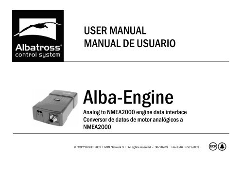
USER MANUAL<br />
MANUAL DE USUARIO<br />
Alba-Engine<br />
Analog to NMEA2000 engine data interface<br />
Conversor de datos de motor analógicos a<br />
NMEA2000<br />
© COPYRIGHT 2009 EMMI Network S.L. All rights reserved - 30728283 Rev PA6 27-01-2009
English version ……………………………………………... 3<br />
Versión en español …………………………………………40<br />
2
Document revisions<br />
Revision Date Comments/Changes<br />
PA1 2006-11-28 First version<br />
PA2 2006-12-22 Minor updates<br />
PA3 2007-01-02 Connection diagram to VDO gauges updated<br />
PA4 2007-01-22 Format review<br />
PA5 2008-07-01 Config Tool configuration (Revision 1.6)<br />
PA6 2009-01-27 Format revision<br />
No part of this document may be reproduced in any form without the written permission of the<br />
copyright owner.<br />
The contents of this document are subject to revision without notice due to continued progress in<br />
methodology, design and manufacturing. EMMI Network SL shall have no liability for any error or<br />
damage of any kind resulting from the use of this document.<br />
The information provided in this document concerning capacity, suitability and performance shall<br />
not be considered commercially binding.<br />
Please note that all capacity figures and dimensioning methods are based on EMMI Network’s SL<br />
own models of how devices behave in a network. The document is intended to be used by<br />
professionally trained personnel. It is strongly recommended to involve EMMI Network SL in<br />
discussions covering the contents of this document.<br />
Any feedback that may help EMMI Network SL improve the documentation and information<br />
methods is welcome.<br />
3
Contents<br />
1. Introduction...................................................................................................................................5<br />
<strong>2.</strong> <strong>Specifications</strong> ...............................................................................................................................6<br />
3. Quick installation ..........................................................................................................................7<br />
3.1. Unpacking the unit ....................................................................................................................7<br />
3.2 Choosing a location to mount the module..................................................................................8<br />
3.<strong>2.</strong>1. Module location if analogue gauges are already present ...................................................8<br />
3.<strong>2.</strong><strong>2.</strong> Module location when the vessel contains analogue gauges………………………………10<br />
3.3 Alba-Engine Connections.........................................................................................................12<br />
3.3. Conexiones del Alba-Engine...................................................................................................12<br />
3.3.1 Alba-Engine connection to a motor with VDO analogue gauges.......................................13<br />
3.3.2 Alternator and mass connection ........................................................................................15<br />
3.3.3 Alba-Engine connection to a motor with no control panel..................................................16<br />
3.3.4 Conexión al bus NMEA2000 .............................................................................................17<br />
3.4 Alba-Engine Configuration .......................................................................................................20<br />
3.4.1 NMEA instance number and address................................................................................21<br />
3.4.2 Sensor calibration and commercial brand choice..............................................................25<br />
3.4.3 Custom sensor calibration .................................................................................................26<br />
3.7 Technical specifications ...........................................................................................................27<br />
3.8 Technical support.....................................................................................................................28<br />
4
1. Introduction<br />
Thanks for purchasing the new <strong>Albatross</strong> digital control system component.<br />
The purpose of this document is to provide the user with the necessary instructions for the<br />
installation and usage of the NMEA 2000 <strong>Albatross</strong> Alba-Engine interface. The NMEA 2000<br />
<strong>Albatross</strong> Alba- Engine is a device intended to monitor NME A2000 marine motors.<br />
The following handbook deals with the Alba-Engine firmware version 1.20.<br />
The following handbook contains important information regarding the installation, operation and<br />
maintenance of your new digital control system. In order to get the best results from the unit, please<br />
read this handbook thoroughly.<br />
5
<strong>2.</strong> <strong>Specifications</strong><br />
The <strong>Albatross</strong> Alba-Engine interface has the following specifications:<br />
• NMEA 2000 interface<br />
• Adapts standard (10-180 ohm) European resistive sensors to the NMEA 2000 network.<br />
• Adapts standard (30-240 ohm) American resistive sensors to the NMEA 2000 network.<br />
• Adapts non-standard resistive sensors () to the NMEA 2000 network<br />
• Adapts VDO technology- equipped sensors (0-5 V) to the NMEA 2000 network<br />
• Can be calibrated both in resistive and voltage modes.<br />
• Can work in parallel with already installed analogue gauges or connected directly to sensors<br />
(in motors without a control panel)<br />
• Motor RPM measurement<br />
• Alternator tension measuring<br />
• Oil pressure measuring<br />
• Boost pressure measuring<br />
• Cooling agent temperature measuring<br />
• Oil temperature measuring<br />
• Cooling water pressure measuring<br />
6
3. Quick installation<br />
To install the Alba-Engine interface, you must complete the following steps. Please study each<br />
referenced individual section for in-depth information on each of them:<br />
1 Unpacking the box.<br />
2 Choose a location for the interface installation.<br />
3 Connect the interface.<br />
4 Interface configuration.<br />
5 Sensor calibration depending on its commercial model.<br />
6 Optional: Custom sensor calibration<br />
3.1. Unpacking the unit<br />
When you unpack the box containing your <strong>Albatross</strong> Alba-Engine interface, you should find the<br />
following elements:<br />
� Alba-Engine interface<br />
� Alba-Engine User Manual<br />
� Bag with the mounting screws<br />
If any of these elements is damaged or not present, please contact Emmi network<br />
7
3.<strong>2.</strong> Choosing a location to mount the module<br />
Figure 1. Module mounting<br />
3.<strong>2.</strong>1. Module location if analogue gauges are already present<br />
Alba-Engine has two types of connection:<br />
1 – Motor sensors connection<br />
2 – NMEA 2000 network connection<br />
8
Thus, the Alba-Engine interface<br />
should be placed between the main<br />
NMEA 2000 network and the<br />
analogue gauges. This is because<br />
you'll have to connect some wires<br />
from the interface to the back of the<br />
gauges and others to the NMEA<br />
network.<br />
Emmi network recommends putting<br />
the Alba- Engine at a maximum<br />
distance of 4 metres from the motor<br />
sensors. The Alba-Engine interface<br />
should be connected to the main<br />
network at a maximum distance of 6<br />
metres, although the user should<br />
consider putting it as close to the main<br />
NMEA network as possible to save in<br />
cable costs.<br />
Figure <strong>2.</strong> Wiring diagram from the module to the motor<br />
sensors<br />
9
3.<strong>2.</strong><strong>2.</strong> Module location when the vessel contains analogue gauges<br />
Alba-Engine has two kinds of connections:<br />
1 – To the motor sensors<br />
2 – To the NMEA 2000 network<br />
Thus, it should be connected between the main NMEA-2000 network and the analogue gauges.<br />
This is because you’ll have to connect some cables to the back of these gauges, and the interface<br />
to the NMEA network.<br />
Emmi network recommends putting Alba-Engine at a maximum distance of 4 metres from the<br />
analogue gauges. It can also be connected to a maximum distance of 6 metres from the NMEA<br />
network, although the boat-owner may consider installing it closer to the main NMEA network in<br />
order to save on the cost of cable.<br />
Interface install location is not critical, and taking into account that all NMEA cables and connector<br />
are watertight (IP 67: protection against temporary immersions in water), the interface could be<br />
placed virtually anywhere on the vessel.<br />
10
Figure 3. Connection diagram of the module in parallel with analogue gauges<br />
11
3.3 Alba-Engine Connections<br />
There are two (see figure) connection points for the Alba-Engine:<br />
1 – Motor sensor connections<br />
2 – NMEA 2000 network connection<br />
You should also take into account that Alba-Engine requires an Alba-USB connected to a laptop<br />
computer to configure the sensors once all the connections are ready<br />
PC with <strong>Albatross</strong> ConfigTool<br />
Alba-USB<br />
Figure 4 Wiring diagram to the Alba-USB<br />
12<br />
Alba-Engine module
3.3.1 Alba-Engine connection to a<br />
motor with VDO analogue gauges<br />
Alba-Engine can work together with analogue<br />
motor gauges without affecting their measuring.<br />
To make this kind of connection you will have to<br />
follow the instructions given in the following<br />
illustrations<br />
3.3.1 .1 Connection to a Tachometer<br />
For this type of connection you'll need to derive<br />
a wire from the (orange-coloured) one marked<br />
W in the gauge, connecting it to input number 2<br />
in the Alba-Engine.<br />
Figure 5. Wiring diagram of the module<br />
to a VDO tachometer.<br />
13<br />
+<br />
-<br />
1.- Signal<br />
<strong>2.</strong>- Ground
3.3.1 .2 Connection to a pressure or<br />
temperature gauge<br />
You'll need to unscrew the connector’s nut in<br />
these gauges and hook a new cable to be<br />
connected to either the 4, 6, 8 or 10 inputs in<br />
the Alba-Engine.<br />
Gauge terminals<br />
Proposed cable<br />
colour<br />
Tensión (+, +12V, I, IGN) Red<br />
Ground (-, ⊥,G) Black<br />
Sensor (S, G) Green<br />
Figure 6. Wiring diagram of the module to a VDO<br />
pressure or temperature analogue gauge.<br />
14
3.3.2 Alternator and mass connection<br />
To connect the alternator’s input and<br />
measure the incoming voltage from it, you’ll<br />
need to connect a cable to the +V connector<br />
in the voltmeter gauge. If your motor’s control<br />
panel has no voltmeter, locate the<br />
alternator’s connection to the battery bank.<br />
Figure 7. Wiring diagram from the module to a VDO<br />
voltmeter<br />
15
3.3.3 Alba-Engine connection to a motor with no control panel<br />
If you have a motor with no control panel, you’ll need to connect Alba-Engine’s inputs directly to the<br />
motor sensors following this diagram:<br />
1- NEGATIVE<br />
2- W SIGNAL/ SENSOR<br />
3- NEGATIVE<br />
4- RESISTIVE SENSOR<br />
5- NEGATIVE<br />
6- RESISTIVE SENSOR<br />
7- NEGATIVE<br />
8- RESISITIVE SENSOR<br />
9- NEGATIVE<br />
10- RESISITIVE SENSOR<br />
11- NEGATIVE<br />
12- ALTERNATOR VOLTAGE MEASURE<br />
Figure 8. Connection Diagram of the module to resistive sensors<br />
16
3.3. 4 Connection to NMEA 2000 bus<br />
The Alba-Engine interface can connect to a NMEA 2000 bus through a 5- pin Micro- C connector.<br />
You’ll have to connect the Alba-Engine interface to the NMEA 2000 bus using a cable of the suitable<br />
length from the module to a T-connector to the main network.<br />
Make sure the cable is firmly connected and the connector’s collar is screwed tight.<br />
Illustration 1<br />
Male<br />
connector<br />
Illustration 2<br />
Female<br />
connector<br />
Figure 9. View of the NMEA<br />
2000 Micro-C connectors<br />
Pin 1: Protective Braid<br />
Pin 2: NET-S. (Positive feed,<br />
+V)<br />
Pin 3: NET-C. (Common feed,<br />
-V)<br />
Pin 4: NET-H. (CAN-H)<br />
Pin 5: NET-L. (CAN-L)<br />
Data:<br />
Blue: NET-H (CAN-H)<br />
White: NET-L.(CAN-L)<br />
External<br />
protective<br />
braiding<br />
Figure 10. Inside view of a Micro-C cable<br />
17<br />
Feed:<br />
Red : NET-S. Positive<br />
feed, + V<br />
Black: NET-C. Common<br />
feed, -V
3.3.4.5 <strong>Albatross</strong> system integration<br />
Figure 15A. Connection diagram of the Alba-Engine to a laptop with Alba-USB and <strong>Albatross</strong> ConfigTool<br />
18
Figura 15B. Connection diagram of the Alba-Engine to an <strong>Albatross</strong> <strong>System</strong><br />
19
3.4 Alba-Engine Configuration<br />
The following illustration shows the main configuration screen for the Alba-Engine interface.<br />
Figure 16. Main dialog box for the configuration of the Alba-Engine<br />
To ensure the proper functioning of your vessel, you need to configure each and every parameter in<br />
this dialog before using it. DON’T USE this product until you have gone through the whole<br />
configuration process, which is explained in detail in the following sections<br />
20
3.4.1 NMEA instance number and address<br />
Most manufacturers use an instance number to reference the motor the interface inserts data about<br />
in the NMEA bus.<br />
We recommend you to use the following table to assign the correct instance number.<br />
Nuber of engines Engine Instante number<br />
1 - 0<br />
2<br />
Babor 0<br />
Estribor 1<br />
3<br />
Babor 0<br />
Central 2<br />
Estribor 1<br />
Table 3. Correspondence of instance number and motor location.<br />
The device’s NMEA address is automatically assigned, so it is not advisable to modify the value<br />
shown for it in the dialog box.<br />
Figure 17. Detail of the NMEA instance number and address<br />
21
3.4.1.1 Impulses per turn for RPM<br />
Impulses per turn tell the Alba-Engine how many signals the alternator receives before the motor<br />
completes a revolution per minute. 100 impulses per turn is the norm, but this value may vary<br />
slightly, depending on the manufacturer of the alternator.<br />
Figure 18. Detail of the impulses per turn for the calibration of RPM field<br />
To calibrate this parameter having a tachometer installed, start the motor, note the tachometer and<br />
main configtool screen’s readings, and change this value while checking the interface’s values on<br />
configtool’s initial screen to adjust the value accordingly.<br />
3.4.1.2 Send 0 signal when RPM are 0?<br />
You’ll notice in some displays that when the motor is stopped while electric supply is still on, the<br />
dials in the digital gauges will go to the maximum value. If this is the case, click on the toggle box to<br />
avoid this behaviour.<br />
Figure 20. Detail of the behaviour when the motor stopped configuration field.<br />
22
3.4.1.3 Choice of parameters to be measured<br />
On inputs 2, 3, 4 and 5 the user can choose what parameters to represent on the digital display.<br />
The available parameters are:<br />
� Boost pressure<br />
� Oil pressure<br />
� Coolant water pressure<br />
� Oil temperature<br />
� Coolant water temperature<br />
Figure 21. Detail of the configuration of parameters to be measured by the module.<br />
Make sure the signal cable for each chosen parameter corresponds to the connector number from<br />
the following table:<br />
Configtool input Parameter<br />
Alba-Engine connector<br />
number<br />
Input 1 RPM Connectors 1 and 2<br />
Input 2 Pressure or Temperature Connector 4<br />
Input 3 Pressure or Temperature Connector 6<br />
Input 4 Pressure or Temperature Connector 8<br />
Input 5 Pressure or Temperature Connector 10<br />
Input 6 Alternator voltage Connector 12<br />
Table 4. Alba-engine inputs and connector number correspondence<br />
23
3.4.1.4 Choice of sensor type<br />
As seen in section 2, motor sensors are either resistive or voltage-based (VDO). You must choose<br />
the appropriate type of sensor connected for each parameter to be measured.<br />
Once you have changed all the necessary fields in the dialog box, click “Accept” for all information<br />
to be programmed and stored in the Alba-Engine interface’s memory.<br />
Figure 2<strong>2.</strong> Detail of the sensor type (resistive or VDO) configuration field<br />
24
3.4.2 Sensor calibration and commercial brand choice<br />
Once sensor and measure units have been chosen, it’s time to<br />
click on the “Calibrate” button for inputs 2 to 5. On pushing it, a<br />
new window will open where you can choose the sensor<br />
gauge’s brand and model to follow.<br />
3.4.<strong>2.</strong>1 Sensor type<br />
This is one of the most important steps in the configuration of<br />
your Alba-Engine unit, as each commercial gauge and sensor<br />
has its own specific configuration, and proper configuration of<br />
these is fundamental to ensure the accuracy of its<br />
measurements.<br />
Figure 23. Dialog box for calibration points in a<br />
sensor.<br />
25
3.4.<strong>2.</strong>2 Voltage correction enabled?<br />
If you connected the Alba-Engine in parallel with VDO gauges, you’ll have to note the tension at<br />
which the configuration is being set in this field (see the initial screen of Installtool, Figure 4) and<br />
check the toggle box marked “enabled”. You’ll also have to enter the voltage value at which the<br />
measurement was made (in figure 23, the example is 12,29 V)<br />
Reference voltage<br />
By checking this field, you’ll tell Alba-Engine that the voltage your ship works on may change during<br />
its functioning, and this will allow you to adjust the gauges’ readings for maximum accuracy at any<br />
time.<br />
3.4.3 Custom sensor calibration<br />
Sensors connected to the Alba- Engine module may need calibration for any of the following<br />
reasons:<br />
1 – A resistive or non-standard tension sensor is being used<br />
2 – A standard sensor is in use, but maximum accuracy is desired.<br />
Annex 1 to this handbook shows you an in-depth explanation of this process.<br />
26
3.7 Technical specifications<br />
SPECIFICATIONS<br />
Magnetic sensor / W signal<br />
Input<br />
4 x Resistive sensor (0 to 250 Ohm)<br />
DC tension:. 32V DC max.<br />
RPM: ±100rpm<br />
Accuracy<br />
Resistive sensor: 1%<br />
DC tension: 1%<br />
NMEA2000 Parameter Group Numbers (PGN’s)<br />
PGN127488 Eng.Pa. Rapid Update<br />
Periodic<br />
PGN127489 Eng. Param. Dynamic<br />
Information<br />
<strong>Control</strong><br />
ELECTRIC SPECIFICATIONS<br />
PGN 126464 Tx/Rx PGN List<br />
PGN 126996 Product Information<br />
PGN 059392 ISO Acknowledge<br />
PGN 059904 ISO Request<br />
PGN 060928 ISO Address Claim<br />
PGN 126208 NMEA Request Group<br />
PGN 126720 Proprietary fast-packet<br />
Tension 9-16V DC from the NMEA bus<br />
Consumption
3.8 Technical support<br />
Emmi Network provides the user with complete technical support through its webpage and a<br />
customer support hotline. Please use any of these means to contact us if a problem arises that you<br />
can’t solve.<br />
Web<br />
Please visit the customer support area in our webpage:<br />
http://www.albatrosscontrol.com/en/tech/<br />
Customer support hotline<br />
If you happen not to have Internet access, please call the following phone number:<br />
+34 96 287 99 44<br />
Help us help you<br />
Whenever you require any technical assistance, please keep the following information at hand.<br />
� Equipment type<br />
� Serial numbers<br />
� Installed software version<br />
28
Revisiones del documento<br />
Revisión Fecha Comentarios/Cambios<br />
PA1 2006-11-28 Primera versión<br />
PA2 2006-12-22 Actualizaciones menores<br />
PA3 2007-01-02 Actualización esquemas conexionado relojes VDO<br />
PA4 2007-01-22 Revisión de formato<br />
PA5 2008-07-01 Configuración con Config Tool (Versión 1.6)<br />
PA6 2009-01-27 Revisión de formato<br />
Ninguna parte de este documento puede ser reproducida sin la aprobación explicita del propietario<br />
del copyright.<br />
Los contenidos de este documento están sujetos a posibles cambios debidos a continuos<br />
progresos en metodología, diseño y fabricación. EMMI Network S.L. declina toda responsabilidad<br />
en caso de error o daño de cualquier tipo como resultado del uso de este documento.<br />
La información proporcionada en este documento relacionado con las capacidades, usos y<br />
prestaciones no debe ser considerada comercialmente vinculante.<br />
Todas las descripciones y figuras están basadas en modelos propios de EMMI Network S.L.<br />
acerca de cómo los dispositivos se comportan en su entorno. El presente documento está<br />
destinado al uso por personal profesional.<br />
Cualquier comentario o mejora que pueda ayudar a EMMI Network S.L. a mejorar la presente<br />
documentación es bienvenida.<br />
30
Tabla de Contenidos<br />
1. Introducción ..................................................................................................................32<br />
<strong>2.</strong> Caracteristicas ..............................................................................................................33<br />
3. Instalación.....................................................................................................................34<br />
3.1. Desembalaje..............................................................................................................34<br />
3.<strong>2.</strong> Montaje del módulo ...................................................................................................35<br />
3.<strong>2.</strong>1. Localización cuando no existan relojes analógicos en el barco...........................35<br />
3.3. Conexiones del Alba-Engine......................................................................................39<br />
3.3.1 Conexiones del Alba-Engine a un motor con relojes VDO ....................................40<br />
3.3.2 Conexiones al alternador y masa .........................................................................42<br />
3.3.3 Conexiones del Alba-Engine a un motor sin panel de control ..............................43<br />
3.3. 4 Conexión al bus NMEA2000................................................................................44<br />
3.4 Configuración del Alba-ENGINE.................................................................................47<br />
3.4.1 Número de instancia y dirección NMEA2000 .......................................................48<br />
3.4.2 Calibración del sensor y selección de la marca comercial ..................................52<br />
3.4.3 Calibración de sensores personalizada................................................................53<br />
3.7 Especificaciones técnicas ...........................................................................................54<br />
3.8 Soporte técnico...........................................................................................................55<br />
31
1. Introducción<br />
Gracias por adquirir su nuevo componente del sistema de control digital <strong>Albatross</strong>.<br />
Este manual contiene información importante relativa a la instalación, operación y mantenimiento<br />
de su nuevo sistema de control digital.<br />
Para obtener el mayor rendimiento del mismo le rogamos que lea completamente este manual.<br />
El propósito de este documento es proveer las instrucciones necesarias para la instalación y uso<br />
del interfaz NMEA2000 <strong>Albatross</strong> Alba-Engine, dispositivo destinado a la sensorización NMEA2000<br />
de motores marinos.<br />
Este manual se corresponde con la versión de firmware del Alba-Engine 1.20<br />
32
<strong>2.</strong> Caracteristicas<br />
El interface Albatros Alba-Engine posee las siguientes características:<br />
• Interface NMEA 2000<br />
• Adapta sensores resistivos estándar europeos de (10-180ohm) a la red NMEA 2000<br />
• Adapta sensores resistivos estándar americanos (30-240 ohm) a la red NMEA 2000<br />
• Adapta sensores resistivos no estándar a la red NMEA 2000<br />
• Adapta sensores con tecnología VDO (0-5 V) a la red NMEA 2000<br />
• Puede ser calibrado tanto en modo resistivo como en modo voltaje<br />
• Trabajo en paralelo con relojes analógicos ya instalados o directamente conectado<br />
• los sensores (motores sin cuadro de mandos)<br />
• Medida de RPM del motor<br />
• Medida de tensión del alternador<br />
• Medida de presión de aceite<br />
• Medida de presión de turbo<br />
• Medida de temperatura de refrigerante<br />
• Medida de temperatura de aceite<br />
• Medida de presión de agua de refrigerante<br />
33
3. Instalación<br />
Para instalar el interface Alba-Engine deberá completar los siguientes pasos. Por favor, estudie<br />
cada uno de las secciones individuales referenciadas para obtener una información más detallada<br />
de cada uno de ellos:<br />
1 Desembalar la caja.<br />
2 Seleccionar una localización para el montaje del interface.<br />
3 Conectar el interface.<br />
4 Configurar el interface.<br />
5 Calibrar los sensores según el modelo comercial.<br />
6 Opcional: Calibración personalizada de sensores.<br />
3.1. Desembalaje<br />
Cuando abra la caja que contiene su interface Albatros Alba-Engine, deberá encontrar los<br />
siguientes elementos:<br />
i. Interface Alba-Engine<br />
ii. Manual de usuario de Alba-Engine<br />
iii. Bolsa con tornillos de sujeción<br />
Si alguno de estos elementos no se encuentra o aparece dañado, por favor, póngase en contacto<br />
con Emmi Network<br />
34
3.<strong>2.</strong> Montaje del módulo<br />
Figura 1. Montaje del módulo.<br />
3.<strong>2.</strong>1. Localización cuando no existan relojes analógicos en el barco<br />
El Alba-Engine tiene dos tipos de conexiones:<br />
� Conexiones con los sensores del motor<br />
� Conexión con la red NMEA 2000<br />
35
El lugar de colocación del interface no<br />
es crítico y teniendo en cuenta las<br />
distancias anteriores y que los cables<br />
y conectores NMEA son aprueba de<br />
agua, (IP 67 protección contra<br />
inmersiones temporales en agua) el<br />
interface podría colocarse<br />
virtualmente en cualquier lugar de la<br />
embarcación.<br />
Emmi Network recomienda colocar el<br />
Alba-Engine a un máximo de 4 metros<br />
de los sensores del motor. El Alba-<br />
Engine debe conectarse a un máximo<br />
de 6 metros de la red troncal, aunque<br />
podría valorase la posibilidad de<br />
colocarlo lo más cerca posible de la<br />
red troncal NMEA de modo que<br />
pueda obtenerse un ahorro en el<br />
coste del cable.<br />
Figura <strong>2.</strong> Esquema de conexión del módulo a sensores de<br />
motor<br />
36
3.<strong>2.</strong><strong>2.</strong> Localización cuando existan relojes analógicos en el barco<br />
El Alba-Engine tiene dos tipos de conexiones:<br />
1 – Conexiones con los sensores del motor<br />
2 – Conexión con la red NMEA 2000<br />
Por tanto, el Alba-Engine debe colocarse entre la red troncal NMEA 2000 y los relojes analógicos.<br />
La razón es que deberá conectar algunos cables a la parte posterior de estos relojes y por otra<br />
parte, conectar el interface a la red NMEA<br />
Emmi network recomienda colocar el Alba-Engine a un máximo de 4 metros de los relojes<br />
analógicos. El Alba-Engine debe conectarse a un máximo de 6 metros de la red troncal, aunque<br />
podría valorase la posibilidad de colocarlo lo más cerca posible de la de la red troncal NMEA de<br />
modo que pueda obtenerse un ahorro en el coste del cable.<br />
El lugar de colocación del interface no es crítico y teniendo en cuenta las distancias anteriores y<br />
que los cables y conectores NMEA son aprueba de agua, (IP 67 protección contra inmersiones<br />
temporales en agua) el interface podría colocarse virtualmente en cualquier lugar de la<br />
embarcación.<br />
37
Figura 3. Esquema de conexión del módulo a relojes analógicos<br />
38
3.3. Conexiones del Alba-Engine<br />
Hay dos puntos de conexión (ver figura) para el Alba-Engine:<br />
1 – Conexiones con los sensores del motor<br />
2 – Conexión con la red NMEA 2000<br />
También deberá tener en cuenta que el Alba-Engine necesita de un Alba-USB conectado a un<br />
ordenador portátil para poder configurar los sensores una vez estén realizadas todas las conexiones)<br />
PC con <strong>Albatross</strong> ConfigTool<br />
Alba-USB<br />
Figura 4. Esquema de conexión del módulo a relojes analógicos<br />
39<br />
Módulo Alba-Engine
3.3.1 Conexiones del Alba-Engine a<br />
un motor con relojes VDO<br />
El Alba-Engine puede funcionar conjuntamente<br />
con los relojes analógicos del motor sin afectar<br />
a sus mediciones. Para realizar este tipo de<br />
conexionado deberá seguir las instrucciones de<br />
la siguientes ilustraciones<br />
3.3.1 .1 Conexión a tacómetro<br />
En esta conexión deberá derivar un cable del<br />
cable marcado como W en el reloj (naranja) y<br />
conectarlo a la entrada número 2 del Alba-<br />
Engine.<br />
Figura 5. Esquema de conexión<br />
del módulo a un tacómetro VDO<br />
40<br />
1.- Señal<br />
<strong>2.</strong>- Masa
3.3.1 .2 Conexión a un reloj de presión<br />
o temperatura<br />
En estos relojes, deberá desenroscar la<br />
tuerca del conector y enganchar un nuevo<br />
cable que deberá conectar a las entradas 4,<br />
6, 8 o 10 del Alba-Engine.<br />
Terminales del reloj<br />
Color del cable<br />
propuesto<br />
Tensión (+, +12V, I, IGN) Rojo<br />
Masa (-, ⊥,G) Negro<br />
Sensor (S, G) Verde<br />
Figura 6. Esquema de conexión del módulo<br />
a un reloj VDO de presión o temperatura<br />
41
3.3.2 Conexiones al alternador y masa<br />
En estos relojes, deberá desenroscar la<br />
tuerca del conector y enganchar un nuevo<br />
cable que deberá conectar a las entradas 4<br />
Para conectar la entrada del alternador y<br />
poder medir el voltaje que proporciona el<br />
mismo, deberá conectar un cable al<br />
conector +V del reloj del voltímetro o , en<br />
caso de que el cuadro del motor no<br />
disponga de voltímetro, localizar el punto<br />
en el que se conecta el alternador al grupo<br />
de baterías.<br />
Figura 7. Esquema de conexión del módulo<br />
a un voltímetro VDO<br />
42
3.3.3 Conexiones del Alba-Engine a un motor sin panel de control<br />
En los motores que no dispongan de panel de control deberá conectar las entradas del Alba-<br />
Engine, directamente a los sensores del motor según el siguiente esquema:<br />
1- NEGATIVO<br />
2- SEÑAL W/CAPTADOR<br />
3- NEGATIVO<br />
4- SENSOR RESISTIVO<br />
5- NEGATIVO<br />
6- SENSOR RESISTIVO<br />
7- NEGATIVO<br />
8- SENSOR RESISTIVO<br />
9- NEGATIVO<br />
10- SENSOR RESISTIVO<br />
11- NEGATIVO<br />
12- MEDIDA VOLTAJE ALTERNADOR<br />
Figura 8. Esquema de conexión del módulo a sensores resistivos<br />
43
3.3. 4 Conexión al bus NMEA2000<br />
EL interface Alba-Engine proporciona una conexión al bus NMEA 2000 a través de un conector Micro-<br />
C de 5 patillas. Usted deberá conectar el interface Alba-Engine al bus NMEA utilizando un cable con<br />
la longitud apropiada que vaya desde el módulo a una “T” de conexión con la red troncal.<br />
Asegúrese de que el cable se ha quedado firmemente conectado y con el collar del conector<br />
firmemente roscado.<br />
Ilustración 5<br />
Conector<br />
Macho<br />
Ilustración 6<br />
Conector<br />
Hembra<br />
Figura 9. Vista de los<br />
conectores NMEA 2000<br />
Micro-C<br />
Pin 1: Malla<br />
Pin 2: NET-S. (Alimentación<br />
positiva, +V)<br />
Pin 3: NET-C. (Alimentación<br />
común, -V)<br />
Pin 4: NET-H. (CAN-H)<br />
Pin 5: NET-L. (CAN-L)<br />
Datos:<br />
Azul : NET-H (CAN-H)<br />
Blanco: NET-L.(CAN-L)<br />
Trenzado protector<br />
externo<br />
Figura 10. Vista interior de un cable Micro-C<br />
44<br />
Alimentación:<br />
Rojo : NET-S.<br />
Alimentación positiva, + V<br />
Negro: NET-C.<br />
Alimentación común, -V
3.3.4.5 Integración con sistema Albatros<br />
Figura 15A. Esquema de conexión del Alba-Engine para configuración del módulo<br />
45
Figura 15B. Esquema de conexión del Alba-Engine para integración en <strong>Albatross</strong> On Board<br />
46
3.4 Configuración del Alba-ENGINE<br />
En la siguiente ilustración puede observarse la pantalla de configuración principal del interface<br />
Alba-Engine.<br />
Figura 16. Cuadro de diálogo principal de configuración del Alba-Engine<br />
Para asegurar un correcto funcionamiento en su barco, es necesario configurar cada uno de los<br />
parámetros que aparecen en el mismo antes de su uso. NO UTILICE este producto hasta haber<br />
realizado todo el proceso de configuración que se especifica en los siguientes puntos.<br />
47
3.4.1 Número de instancia y dirección NMEA2000<br />
La mayoría de fabricantes utilizan el número de instancia para referenciar el motor al que<br />
corresponden los datos que el interface inserta en el bus NMEA.<br />
Le recomendamos que utilice la siguiente tabla para asignar el número de instancia correcto:<br />
Número de motores Motor Número de instancia<br />
1 - 0<br />
2<br />
3<br />
Babor 0<br />
Estribor 1<br />
Babor 0<br />
Central 2<br />
Estribor 1<br />
Tabla 3. Correspondencias entre número de instancia y localización del motor.<br />
La dirección NMEA del dispositivo se asigna de forma automática, por lo que no es recomendable<br />
modificar el valor que aparece en el cuadro de dialogo<br />
Figura 17. Detalle de campos de Instancia y dirección NMEA<br />
48
3.4.1.1 Impulsos por vuelta para las RPM<br />
Los impulsos por vuelta le indican al Alba-Engine cuantas señales le llegan del alternador antes de<br />
que el motor haya dado una revolución por minuto. Lo usual son 100 impulsos por vuelta pero es<br />
posible que varíe ligeramente según el fabricante del alternador.<br />
Figura 18. Detalle del campo de impulsos por vuelta para calibración de RPMs<br />
Para calibrar este parámetro, si tiene un tacómetro instalado, arranque el motor observe las<br />
lecturas del tacómetro y de la pantalla inicial del ConfigTool y vaya variando el valor y<br />
comprobando en la pantalla inicial de ConfigTool los valores que proporciona el interface para<br />
ajustar el valor convenientemente.<br />
3.4.1.2 ¿Mandar señal 0 cuando RPM sean 0?<br />
En algunos displays observará que al parar el motor y dejar la alimentación encendida, las agujas<br />
de los relojes digitales se irán al máximo. En este caso, marque la casilla de verificación para evitar<br />
este comportamiento.<br />
Figura 19. Detalle del campo de configuración del comportamiento con motor parado.<br />
49
3.4.1.3 Selección de los parámetros a medir<br />
En las entradas 2, 3, 4 y 5 podemos elegir los parámetros que vamos a representar en nuestra<br />
pantalla digital. Estos parámetros pueden ser:<br />
� Presión de turbo<br />
� Presión de aceite<br />
� Presión de agua de refrigeración<br />
� Temperatura de aceite<br />
� Temperatura de agua de refrigeración<br />
Figura 20. Detalle del campo de configuración de los parámetros a medir por el módulo.<br />
Asegúrese que el cable de señal de cada parámetro seleccionado se corresponde con el número<br />
de conector de la siguiente tabla:<br />
Entrada configtool Parámetro Número de conectores del<br />
Alba-Engine<br />
Entrada 1 RPM Conector 1 y 2<br />
Entrada 2 Presión o temperatura Conector 4<br />
Entrada 3 Presión o temperatura Conector 6<br />
Entrada 4 Presión o temperatura Conector 8<br />
Entrada 5 Presión o temperatura Conector 10<br />
Entrada 6 Voltaje del alternador Conector 12<br />
Tabla 4. Correspondencia entre entradas del Alba-Engine y su número de conector<br />
50
3.4.1.4 Selección del tipo de Sensores<br />
Como se ha visto en la sección 2, los sensores del motor pueden ser resistivos o por voltaje<br />
(VDO). Seleccione para cada uno de los parámetros a medir el tipo de sensor conectado.<br />
Una vez haya cambiado todos los campos del cuadro de diálogo. Pulse el botón “Aceptar” para<br />
que la información se programe y almacene en la memoria del interface Alba-Engine.<br />
Figura 21. Detalle del campo de configuración de tipo de sensor. (VDO o Resistivo)<br />
51
3.4.2 Calibración del sensor y selección de la marca comercial<br />
Una vez ha seleccionado qué sensor y qué medida está<br />
realizando, es el momento de pulsar el botón “Calibrar” para<br />
cada una de las entradas de la 2 a la 5. Al pulsar este botón se<br />
abrirá una nueva ventana en la que podrá seleccionar la marca<br />
y modelo del sensor reloj a modelizar.<br />
3.4.<strong>2.</strong>1 Tipo de sensor<br />
Este es uno de los puntos más importantes de la configuración<br />
ya que cada reloj y sensor comercial tiene una configuración<br />
determinada y es fundamental completar este paso para<br />
asegurar la máxima precisión en las medidas.<br />
Figura 2<strong>2.</strong> Cuadro de diálogo de puntos de<br />
calibración para un sensor de voltaje.<br />
52
3.4.<strong>2.</strong>2 Corrección de voltaje ¿habilitado?<br />
Si usted ha conectado el Alba-Engine en paralelo con relojes VDO, deberá apuntar en este campo<br />
la tensión a la que está realizando la configuración (ver en pantalla inicial de ConfigTool, figura 4) y<br />
marcar la casilla de verificación “habilitado”. Por otra parte, deberá introducir el valor del voltaje en<br />
el que ha realizado la medición. (En la figura 22 del ejemplo es 12 V)<br />
Voltaje de Referencia<br />
Marcando este campo, le indicará al Alba-Engine que el voltaje al que trabaja su embarcación<br />
puede variar durante el funcionamiento de la misma y le permitirá ajustar en cada momento la<br />
lectura de los indicadores para proporcionar la máxima precisión en las medidas.<br />
3.4.3 Calibración de sensores personalizada<br />
El los sensores conectados al módulo Alba-Engine pueden necesitar ser calibrados por alguna de<br />
las siguientes razones:<br />
1 – Se esté usando un sensor resistivo o de tensión no estándar<br />
2 – Se está usando un sensor estándar pero se desea máxima precisión<br />
En el anexo 1 de este manual encontrará una explicación detallada de cómo realizar este proceso.<br />
53
3.7 Especificaciones técnicas<br />
ESPECIFICACIONES<br />
Entrada<br />
Precisión<br />
Sensor magnético / Señal W<br />
4 x Sensor resistivo (0 a 250 Ohm)<br />
Tensión DC: máx. 32V DC<br />
RPM: ±100rpm<br />
Sensor resistivo: 1%<br />
Tensión DC: 1%<br />
NMEA2000 Parameter Group Numbers (PGN’s)<br />
Periódico<br />
PGN127488 Eng.Pa. Rapid Update<br />
PGN127489 Eng. Param. Dynamic<br />
PGN 126464 Tx/Rx PGN List<br />
Información PGN 126996 Product Information<br />
<strong>Control</strong><br />
ELÉCTRICAS<br />
PGN 059392 ISO Acknowledge<br />
PGN 059904 ISO Request<br />
PGN 060928 ISO Address Claim<br />
PGN 126208 NMEA Request Group<br />
PGN 126720 Proprietary fast-packet<br />
Tensión 9-16V DC del bus NMEA<br />
Consumo
3.8 Soporte técnico<br />
Emmi Network proporciona un completo soporte técnico en la Web y a través de la línea telefónica<br />
de soporte. Por favor, use cualquiera de estos métodos si no puede resolver un problema.<br />
Web<br />
Por favor, visite el área de soporte técnico en:<br />
http://www.albatrosscontrol.com/es/tech/<br />
E-mail<br />
Puede ponerse en contacto con el soporte técnico en la dirección: support@emminet.com<br />
Línea telefónica de ayuda.<br />
Si usted no dispone de acceso a la web, por favor llame al teléfono: +34 962 879 944<br />
Ayúdenos a ayudarle<br />
Cuando requiera del servicio de asistencia técnica, por favor tenga disponible la siguiente<br />
información:<br />
� Tipo de equipamiento<br />
� Números de serie<br />
� Versión de software instalado<br />
55
![PDF[0.59Mb] - Albatross Control System](https://img.yumpu.com/28676183/1/190x132/pdf059mb-albatross-control-system.jpg?quality=85)