
You also want an ePaper? Increase the reach of your titles
YUMPU automatically turns print PDFs into web optimized ePapers that Google loves.
QUESTE ISTRUZIONI DEVONO ESSERE ALLEGATE<br />
ALL’APPARECCHIO<br />
THESE INSTRUCTIONS SHOULD BE ATTACHED TO<br />
THE APPARATUS<br />
DIESE ANLEITUNGEN MÜßEN JEDE GERÄT<br />
BEGLEITEN<br />
CETTES INSTRUCTIONS DOIVENT ACCOMPAGNER<br />
L’APPAREIL<br />
ESTAS INSTRUCCIONES SE DEBEN ANEXAR<br />
APARATO<br />
AL<br />
ESTAS INSTRUÇÕES DEVEM ACOMPANHAR O<br />
APARELHO<br />
1<br />
<strong>YVL200</strong><br />
BPT S.p.A.<br />
Via Roma, 41<br />
30020 Cinto Caomaggiore/VE/Italy<br />
http: www.bpt.it/e-mail: info@bpt.it<br />
I<br />
ISTRUZIONI PER L’USO<br />
E L’INSTALLAZIONE<br />
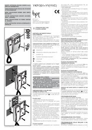
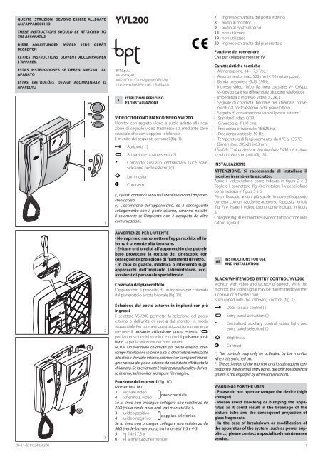
VIDEOCITOFONO BIANCO/NERO <strong>YVL200</strong><br />
Monitor con segreto video e audio adatto alla ricezione<br />
di segnale video trasmesso sia mediante cavo<br />
coassiale che con doppino telefonico.<br />
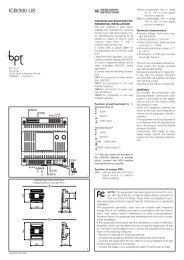
È munito dei seguenti comandi (fig. 1):<br />
Apriporta ( 1 )<br />
Attivazione posto esterno ( 2 )<br />
Comando ausiliario centralizzato (luce scale,<br />
selezione posto esterno) ( 1 )<br />
Luminosità<br />
Contrasto<br />
( 1 ) Questi comandi sono utilizzabili solo con l’apparecchio<br />
acceso.<br />
( 2 ) L’accensione dell’apparecchio, ed il conseguente<br />
collegamento con il posto esterno, saranno possibili<br />
solamente se l’impianto non è occupato da altre<br />
comunicazioni.<br />
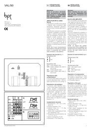
7 ingresso chiamata dal posto esterno<br />
8 audio al monitor<br />
9 audio al posto esterno<br />
18 non utilizzato<br />
19 non utilizzato<br />
20 ingresso chiamata dal pianerottolo<br />
Funzione del connettore<br />
CN1 per collegare monitor YV.<br />
Caratteristiche tecniche<br />
• Alimentazione: 14÷17,5 Vcc.<br />
• Assorbimento: max. 508 mA (< 10 mA a riposo).<br />
• Banda passante a -3dB: 5MHz.<br />
• Ingresso video: 1Vpp da linea coassiale; V+ 0,6Vpp,<br />
V– 0,6Vpp da linea differenziale (doppino telefonico).<br />
• Impedenza d’ingresso video: ≥22kΩ<br />
• Segnale di chiamata: bitonale per chiamate provenienti<br />
dal posto esterno o dal pianerottolo.<br />
• Segreto di conversazione verso il posto esterno.<br />
• Standard video: CCIR.<br />
• Cinescopio: 4” (10 cm).<br />
• Frequenza orizzontale: 15.625 Hz.<br />
• Frequenza verticale: 50 Hz.<br />
• Temperatura di funzionamento: da 0 °C a +35 °C.<br />
• Dimensioni: 205x215x63mm.<br />
Il fusibile F1 di protezione tipo ritardato T 630 mA è situato<br />
sul circuito stampato (fig. 10).<br />
INSTALLAZIONE<br />
ATTENZIONE. Si raccomanda di installare il<br />
monitor in ambiente asciutto.<br />
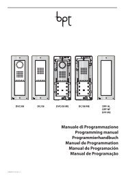
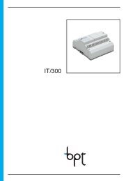
Aprire il videocitofono come indicato in figura 2 e 3.<br />
Togliere il connettore (fig. 4) e installare il videocitofono<br />
come indicato in figura 5 e 6.<br />
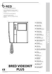
Per un fissaggio ancora più stabile rimuovere il supporto<br />
cornetta con un cacciavite attraverso l’apposita feritoia<br />
(fig. 7) e fissare il videocitofono come indicato in figura<br />
8.<br />
Collegare (fig. 4) e rimontare il videocitofono come indicato<br />
in figura 9.<br />
1<br />
2<br />
AVVERTENZE PER L’UTENTE<br />
- Non aprire o manomettere l’apparecchio; all’interno<br />
è presente alta tensione.<br />
- Evitare urti o colpi all’apparecchio che potrebbero<br />
provocare la rottura del cinescopio con<br />
conseguente proiezione di frammenti di vetro.<br />
- In caso di guasto, modifica o intervento sugli<br />
apparecchi dell’impianto (alimentatore, ecc.)<br />
avvalersi di personale specializzato.<br />
Chiamata dal pianerottolo<br />
L’apparecchio è provvisto di un ingresso per chiamata<br />
dal pianerottolo a nota bitonale (fig. 11).<br />
Selezione del posto esterno in impianti con più<br />
ingressi<br />
Il selettore VSI/200 permette la selezione del posto<br />
esterno o dell’unità di ripresa dal monitor in modo<br />
sequenziale. Per ottenere questo tipo di funzionamento<br />
premere il pulsante attivazione posto esterno ( )<br />
per l’accensione del monitor e quindi il pulsante ausiliario<br />
(•) per la selezione dei posti esterni.<br />
NOTA. Un’eventuale chiamata dal posto esterno interrompe<br />
la selezione in corso e, se la chiamata è indirizzata<br />
allo stesso derivato interno, sul monitor compare l’immagine<br />
ripresa dal posto esterno da cui è stata effettuata la<br />
chiamata. Se la chiamata è indirizzata ad un altro derivato<br />
interno, sul monitor scompare l’immagine.<br />
GB<br />
INSTRUCTIONS FOR USE<br />
AND INSTALLATION<br />
BLACK/WHITE VIDEO ENTRY CONTROL <strong>YVL200</strong><br />
Monitor with video and secrecy of speech. With this<br />
monitor, the video signal may be transmitted by either<br />
a coaxial or a twisted pair.<br />
Is equipped with the following controls (fig. 1):<br />
Door release control ( 1 )<br />
Entry panel activation ( 2 )<br />
Centralized auxiliary control (stairs light and<br />
entry panel selection) ( 1 )<br />
Brightness<br />
Contrast<br />
( 1 ) The controls may only be activated by the monitor<br />
when it is switched on.<br />
( 2 ) The activation of the monitor and its subsequent connection<br />
to the external entry panel, are only possible if the<br />
system is not engaged by other conversations.<br />
08-11-2011/24836300<br />
2<br />
3<br />
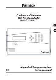
Funzione dei morsetti (fig. 10)<br />
Morsettiera M1<br />
3 segnale video<br />
cavo coassiale<br />
4 schermo s. video<br />
Se la linea non prosegue collegare una resistenza da<br />
75Ω (viola-verde-nero-oro) tra i morsetti 3 e 4.<br />
3 s.video positivo<br />
doppino telefonico<br />
4 s.video negativo<br />
Se la linea non prosegue collegare una resistenza da<br />
56Ω (verde-blu-nero-oro) tra i morsetti 3-5 e 4-5.<br />
5 – 14÷17,5 V<br />
6 + alimentazione monitor<br />
WARNINGS FOR THE USER<br />
- Please do not open or tamper the device (high<br />
voltage!).<br />
- Please avoid knocking or bumping the apparatus<br />
as it could result in the breakage of the<br />
picture tube and the consequent projection of<br />
glass fragments.<br />
- In the case of breakdown or modification of<br />
the apparatus of the system (such as power supplier...)<br />
please contact a specialized maintenance<br />
service.<br />
1
Personal door-bell button<br />
The monitor fits a landing call input with a two-tone<br />
call, fig. 11.<br />
D<br />
BEDIENUNGS- UND<br />
INSTALLATIONSANLEITUNG<br />
83,5 mm<br />
A<br />
4<br />
5<br />
6<br />
Entry panel selection in systems<br />
with several entrances<br />
The VSI/200 selector allows you to select the external<br />
entry panel or camera from the monitor in sequential<br />
mode. To operate the selector: press the entry panel<br />
activation button ( ) to turn-on the monitor; and<br />
then press the auxiliary button (•) to select the entry<br />
panels.<br />
NOTE. In the event a call is made from the entry panel, the<br />
selection in progress is interrupted.<br />
If the external call is addressed to the monitor making the<br />
selection, the monitor displays the image filmed at the<br />
external entry from where the call is addressed to another<br />
monitor, the image disappears from the monitor.<br />
Function of each terminal (fig. 10)<br />
Terminal block M1<br />
3 video signal<br />
coaxial cable<br />
4 video signal shield<br />
If the video line ends at this monitor, connect a 75Ω (violetgreen-black-gold)<br />
resistor between terminals 3 and 4.<br />
3 pos. video signal<br />
twisted pair<br />
4 neg. video signal<br />
If the video line ends at this monitor, connect a 56Ω (greenblue-black-gold)<br />
resistor between terminals 3-5 and 4-5.<br />
5 – 14÷17,5 V<br />
6 + supply voltage to monitor<br />
7 call input from entry panel<br />
8 audio to monitor<br />
9 audio to entry panel<br />
18 not used<br />
19 not used<br />
20 call input from landing<br />
Function of connector<br />
CN1 to connect to monitor YV.<br />
Technical features<br />
• Supply voltage: 14÷17,5 VDC.<br />
• Current demand: max. 508 mA (
2<br />
8<br />
• Durchlaßbereich bei -3dB: 5MHz.<br />
• Videoeingang:1Vss von Koaxialkabel; V + 0,6Vss, V-<br />
0,6ss von Differentialleitung (Telefon-Kabel).<br />
• Video-Eingangsimpedanz: ≥22kΩ<br />
• Rufsignal: Zweitonsignal für Anruf von der<br />
Außenstation oder Etagenanruf.<br />
• Mithörsperre zur Außenstation.<br />
• CCIR Standard.<br />
• Bildröhre: 4-Zoll (10 cm).<br />
• Durchlaßbereich bei -3 dB: 5 MHz.<br />
• Horizontalfrequenz: 15.625 Hz.<br />
• Verticalfrequenz: 50 Hz.<br />
• Betriebstemperatur: von 0 °C bis +35 °C.<br />
• Abmessungen: 205x215x63 mm.<br />
Der Monitor wird durch die Sicherung F1 träge Type T<br />
630mA - angebracht auf der Monitorplatine, geschütz<br />
(Abb. 10).<br />
INSTALLATIONSANWEISUNG<br />
ACHTUNG. Es wird empfohlen den Monitor an<br />
einer geschützten Stelle zu installieren.<br />
Die Videosprechanlage wie in den Abbildungen 2<br />
und 3 gezeigt, öffnen. Den Steckverbinder (Abb. 4)<br />
entfernen und die Videosprechanlage wie in den<br />
Abbildungen 5 und 6 gezeigt, installieren.<br />
Für eine stabilere Befestigung die Hörerhalterung mit<br />
einem Schraubenzieher über den entsprechenden<br />
Schlitz (Abb. 7) abnehmen und die Videosprechanlage<br />
wie in der Abbildung 8 gezeigt, befestigen.<br />
Die Videosprechanlage wie in der Abbildung 9 gezeigt,<br />
anschließen (Abb. 4) und wieder montieren.<br />
Pour obtenir ce type de fonctionnement presser le<br />
bouton-poussoir insertion poste externe ( ) pour<br />
l’allumage du récepteur vidéo, puis le bouton auxiliaire<br />
(•) pour la sélection des postes exterieurs.<br />
NOTE. Un appel éventuel à partir du poste extérieur interrompt<br />
la sélection en cours et, si l’appel s’adresse au même<br />
poste intérieur, l’image reprise du poste extérieur d’où a<br />
été effectué l’appel apparaît sur le récepteur vidéo.<br />
Si l’appel s’adresse à un autre poste intérieur, l’image<br />
disparaît du récepteur vidéo.<br />
Fonction des bornes (fig. 10)<br />
Bornier M1<br />
3 signal vidéo<br />
câble coaxial<br />
4 blindage s. vidéo<br />
Si la ligne ne continue pas, connecter une résistance de<br />
75Ω (violet-vert-noir-or) entre les bornes 3 et 4.<br />
3 s.vidéo positif<br />
paire torsadé<br />
4 s.vidéo negatif<br />
Si la ligne ne continue pas, connecter une résistance de<br />
56Ω (vert-bleu-noir-or) entre les bornes 3-5 et 4-5.<br />
5 – 14÷17,5 V alimentation<br />
6 + récepteur vidéo<br />
7 entrée appel depuis le poste extérieur<br />
8 audio au récepteur vidéo<br />
9 audio au poste extérieur<br />
18 non utilisé<br />
19 non utilisé<br />
20 entrée appel depuis la porte palière<br />
Fonction de connecteur<br />
CN1 pour relier le moniteur YV.<br />
M1<br />
1<br />
20<br />
19<br />
18<br />
9<br />
8<br />
76543<br />
9<br />
F<br />
INSTRUCTIONS POUR L’ EMPLOI<br />
ET L’ INSTALLATION<br />
PORTIER VIDÉO BLANC/NOIR <strong>YVL200</strong><br />
Récepteur vidéo avec secret vidéo et de conversation<br />
convenant pour la réception du signal vidéo transmis<br />
soit par câble coaxial, soit par paire torsadé.<br />
Il est muni des commandes suivantes (fig. 1):<br />
Commande ouvre-porte ( 1 )<br />
Mise en marche du poste extérieur ( 2 )<br />
Commande auxiliaire centralisée (minuterie,<br />
sélection du poste extérieur) ( 1 )<br />
Luminosité<br />
Caractéristiques techniques<br />
• Alimentation: 14÷17,5 Vcc.<br />
• Consommation: 508 mA maxi (
Mando auxiliar centralizado (luz escalera, seleccion<br />
placa esterior) ( 1 )<br />
Luminosidad<br />
Contrasto<br />
( 1 ) Los mandos se pueden accionar desde el monitor<br />
solo con el aparato encendido.<br />
( 2 ) El encendido del aparato y la consiguiente conexión<br />
con la placa exterior se pueden realizar solo si el equipo<br />
no está ocupado por otras comunicaciones.<br />
ADVERTENCIAS PARA EL USUARIO<br />
- No abrir ni manipular el aparato: en el interior<br />
hay alta tension.<br />
- Evitar choques y golpes al aparato que puedan<br />
causar la implosión del tubo catódico y proyección<br />
de fragmentos de vidrio.<br />
- En caso de avería o necesidad de modificación o<br />
intervención sobre los aparatos de la instalación (alimentador,<br />
etc.) dirigirse al personal especializado.<br />
Llamada desde el rellano<br />
El monitor está provisto de una entrada para llama<br />
desde el rellano a nota bitonal (fig. 11).<br />
Selección de la placa exterior en equipos con<br />
varias entradas<br />
El selector VSI/200 permite seleccionar la placa exterior o<br />
la unidad de captación desde los monitores en modo<br />
secuencial. Para obtener este tipo de funcionamiento,<br />
pulsar primero el botón de activación de la placa exterior<br />
( ) para encender el monitor, y luego el botón<br />
auxiliar (•) para la selección de las placas exteriores.<br />
NOTA. Una eventual llamada desde la placa exterior<br />
interrumpe la selección en curso y, si está dirigida al<br />
mismo derivado interno, en el monitor aparece la<br />
imagen captada en la placa exterior desde el cual<br />
proviene.<br />
Si la llamada está dirigida a otro derivado interno, en el<br />
monitor desaparece la imagen.<br />
Funciones de los bornes (fig. 10)<br />
Bornera M1<br />
3 señal de vídeo<br />
cable coaxial<br />
4 pantalla s. de vídeo<br />
Si la linea no continúa conectar una resistencia de 75Ω<br />
(violeta-verde-negro-oro) entre los bornes 3 y 4.<br />
3 s. de vídeo positiva<br />
cable telefónico<br />
4 s. de vídeo negativa<br />
Si la linea no continúa conectar una resistencia de 56Ω<br />
(verde-azul-negro-oro) entre los bornes 3-5 y 4-5.<br />
5 – 14 ÷ 17,5V<br />
6 + alimentación monitor<br />
7 entrada de la llamada desde la placa exterior<br />
8 audio al monitor<br />
9 audio a la placa exterior<br />
18 no se usa<br />
19 no se usa<br />
20 entrada de la llamada desde el rellano<br />
Función de conectore<br />
CN1 para conectar el monitor YV.<br />
Características técnicas<br />
• Alimentación: 14÷17,5 Vcc.<br />
• Consumo: max. 508 mA (