Manuale di Installazione Installation Manual Handbuch für den ... - Bpt
Manuale di Installazione Installation Manual Handbuch für den ... - Bpt
Manuale di Installazione Installation Manual Handbuch für den ... - Bpt

You also want an ePaper? Increase the reach of your titles
YUMPU automatically turns print PDFs into web optimized ePapers that Google loves.
NOVA<br />
OPHERA LYNEA<br />
LYNEA BASIC<br />
MITHO<br />
VAS/100.30<br />
DVC/01<br />
DVC/01 ME<br />
<strong><strong>Manual</strong>e</strong> <strong>di</strong> <strong>Installazione</strong><br />
<strong>Installation</strong> <strong>Manual</strong><br />
<strong>Handbuch</strong> für <strong>den</strong> Installateur<br />
Manuel d’<strong>Installation</strong><br />
<strong>Manual</strong> para el Instalador<br />
<strong>Manual</strong> para o Instalador<br />
BVKIT<br />
23-12-10/24801012
INDICE<br />
LYNEA BASIC (YVL301) . . . . . . . . . . . . . . . . . . PAG. 6<br />
<strong>Installazione</strong>. . . . . . . . . . . . . . . . . . . . . . . . . . . . . . . . . . . . . 6<br />
Morsettiere. . . . . . . . . . . . . . . . . . . . . . . . . . . . . . . . . . . . . . 7<br />
Funzione deI connettori. . . . . . . . . . . . . . . . . . . . . . . . . . . . 7<br />
Caratteristiche tecniche . . . . . . . . . . . . . . . . . . . . . . . . . . . .7<br />
Selezioni . . . . . . . . . . . . . . . . . . . . . . . . . . . . . . . . . . . . . . . . 8<br />
Accessori. . . . . . . . . . . . . . . . . . . . . . . . . . . . . . . . . . . . . . . . 8<br />
Programmazione . . . . . . . . . . . . . . . . . . . . . . . . . . . . . . . . .9<br />
LYNEA (YV-YVC). . . . . . . . . . . . . . . . . . . . . . . PAG. 10<br />
<strong>Installazione</strong>. . . . . . . . . . . . . . . . . . . . . . . . . . . . . . . . . . . . 10<br />
Morsettiere. . . . . . . . . . . . . . . . . . . . . . . . . . . . . . . . . . . . . 11<br />
Funzione deI connettorI. . . . . . . . . . . . . . . . . . . . . . . . . . . 11<br />
Selezioni . . . . . . . . . . . . . . . . . . . . . . . . . . . . . . . . . . . . . . . 12<br />
Caratteristiche tecniche . . . . . . . . . . . . . . . . . . . . . . . . . . .12<br />
Accessori. . . . . . . . . . . . . . . . . . . . . . . . . . . . . . . . . . . . . . . 12<br />
Programmazione . . . . . . . . . . . . . . . . . . . . . . . . . . . . . . . .13<br />
OPHERA-OPHERA/B . . . . . . . . . . . . . . . . . . . . PAG. 14<br />
<strong>Installazione</strong>. . . . . . . . . . . . . . . . . . . . . . . . . . . . . . . . . . . . 14<br />
Accessori. . . . . . . . . . . . . . . . . . . . . . . . . . . . . . . . . . . . . . . 16<br />
Morsettiere. . . . . . . . . . . . . . . . . . . . . . . . . . . . . . . . . . . . . 17<br />
Selezioni . . . . . . . . . . . . . . . . . . . . . . . . . . . . . . . . . . . . . . . 17<br />
Caratteristiche tecniche . . . . . . . . . . . . . . . . . . . . . . . . . . .18<br />
Programmazione . . . . . . . . . . . . . . . . . . . . . . . . . . . . . . . .19<br />
NOVA . . . . . . . . . . . . . . . . . . . . . . . . . . . . . .PAG. 20<br />
<strong>Installazione</strong>. . . . . . . . . . . . . . . . . . . . . . . . . . . . . . . . . . . . 20<br />
Morsettiere modulo video . . . . . . . . . . . . . . . . . . . . . . . . .23<br />
Morsettiere modulo au<strong>di</strong>o . . . . . . . . . . . . . . . . . . . . . . . . . 23<br />
Funzione dei connettori . . . . . . . . . . . . . . . . . . . . . . . . . . . 23<br />
Selezioni modulo au<strong>di</strong>o . . . . . . . . . . . . . . . . . . . . . . . . . . .24<br />
Selezioni modulo video . . . . . . . . . . . . . . . . . . . . . . . . . . .24<br />
Caratteristiche tecniche . . . . . . . . . . . . . . . . . . . . . . . . . . .24<br />
MITHO . . . . . . . . . . . . . . . . . . . . . . . . . . . . .PAG. 26<br />
<strong>Installazione</strong>. . . . . . . . . . . . . . . . . . . . . . . . . . . . . . . . . . . . 26<br />
Morsettiere. . . . . . . . . . . . . . . . . . . . . . . . . . . . . . . . . . . . . 28<br />
Selezioni . . . . . . . . . . . . . . . . . . . . . . . . . . . . . . . . . . . . . . . 28<br />
Caratteristiche tecniche . . . . . . . . . . . . . . . . . . . . . . . . . . .29<br />
Messa in servizio. . . . . . . . . . . . . . . . . . . . . . . . . . . . . . . . . 29<br />
Accessori. . . . . . . . . . . . . . . . . . . . . . . . . . . . . . . . . . . . . . . 29<br />
VAS/100.30 . . . . . . . . . . . . . . . . . . . . . . . . . .PAG. 30<br />
<strong>Installazione</strong>. . . . . . . . . . . . . . . . . . . . . . . . . . . . . . . . . . . . 30<br />
Caratteristiche Tecniche . . . . . . . . . . . . . . . . . . . . . . . . . . . 31<br />
Morsettiere. . . . . . . . . . . . . . . . . . . . . . . . . . . . . . . . . . . . . 31<br />
DVC/01-DVC/01 ME. . . . . . . . . . . . . . . . . . . . . PAG. 32<br />
<strong>Installazione</strong> da parete. . . . . . . . . . . . . . . . . . . . . . . . . . . . 32<br />
<strong>Installazione</strong> da incasso . . . . . . . . . . . . . . . . . . . . . . . . . . .33<br />
Affiancabilità a parete . . . . . . . . . . . . . . . . . . . . . . . . . . . .34<br />
Affiancabilità a incasso. . . . . . . . . . . . . . . . . . . . . . . . . . . . 36<br />
Accessori. . . . . . . . . . . . . . . . . . . . . . . . . . . . . . . . . . . . . . . 37<br />
Funzione dei morsetti. . . . . . . . . . . . . . . . . . . . . . . . . . . . . 38<br />
Regolazioni e funzioni dei led . . . . . . . . . . . . . . . . . . . . . .39<br />
Caratteristiche Tecniche . . . . . . . . . . . . . . . . . . . . . . . . . . . 39<br />
Programmazione . . . . . . . . . . . . . . . . . . . . . . . . . . . . . . . .40<br />
CONTENTS<br />
LYNEA BASIC (YVL301) . . . . . . . . . . . . . . . . . . PAG. 6<br />
<strong>Installation</strong> . . . . . . . . . . . . . . . . . . . . . . . . . . . . . . . . . . . . . . 6<br />
Terminal boards . . . . . . . . . . . . . . . . . . . . . . . . . . . . . . . . . . 7<br />
Function of connector. . . . . . . . . . . . . . . . . . . . . . . . . . . . . . 7<br />
Technical features. . . . . . . . . . . . . . . . . . . . . . . . . . . . . . . . . 7<br />
Selections . . . . . . . . . . . . . . . . . . . . . . . . . . . . . . . . . . . . . . . 8<br />
Accessories . . . . . . . . . . . . . . . . . . . . . . . . . . . . . . . . . . . . . . 8<br />
Programming . . . . . . . . . . . . . . . . . . . . . . . . . . . . . . . . . . . . 9<br />
LYNEA (YV-YVC). . . . . . . . . . . . . . . . . . . . . . . PAG. 10<br />
<strong>Installation</strong> . . . . . . . . . . . . . . . . . . . . . . . . . . . . . . . . . . . . . 10<br />
Terminal boards . . . . . . . . . . . . . . . . . . . . . . . . . . . . . . . . . 11<br />
Function of connectors. . . . . . . . . . . . . . . . . . . . . . . . . . . . 11<br />
Selections . . . . . . . . . . . . . . . . . . . . . . . . . . . . . . . . . . . . . . 12<br />
Technical features. . . . . . . . . . . . . . . . . . . . . . . . . . . . . . . . 12<br />
Accessories . . . . . . . . . . . . . . . . . . . . . . . . . . . . . . . . . . . . . 12<br />
Programming . . . . . . . . . . . . . . . . . . . . . . . . . . . . . . . . . . . 13<br />
OPHERA-OPHERA/B . . . . . . . . . . . . . . . . . . . . PAG. 14<br />
<strong>Installation</strong> . . . . . . . . . . . . . . . . . . . . . . . . . . . . . . . . . . . . . 14<br />
Accessories . . . . . . . . . . . . . . . . . . . . . . . . . . . . . . . . . . . . . 16<br />
Terminal boards . . . . . . . . . . . . . . . . . . . . . . . . . . . . . . . . . 17<br />
Selections . . . . . . . . . . . . . . . . . . . . . . . . . . . . . . . . . . . . . . 17<br />
Technical features. . . . . . . . . . . . . . . . . . . . . . . . . . . . . . . . 18<br />
Programming . . . . . . . . . . . . . . . . . . . . . . . . . . . . . . . . . . . 19<br />
NOVA . . . . . . . . . . . . . . . . . . . . . . . . . . . . . .PAG. 20<br />
<strong>Installation</strong> . . . . . . . . . . . . . . . . . . . . . . . . . . . . . . . . . . . . . 20<br />
Video module terminal board . . . . . . . . . . . . . . . . . . . . . . 23<br />
Au<strong>di</strong>o module terminal board . . . . . . . . . . . . . . . . . . . . . . 23<br />
Function of connectors. . . . . . . . . . . . . . . . . . . . . . . . . . . . 23<br />
Au<strong>di</strong>o module selections . . . . . . . . . . . . . . . . . . . . . . . . . . 24<br />
Video module selections . . . . . . . . . . . . . . . . . . . . . . . . . . .24<br />
Technical features. . . . . . . . . . . . . . . . . . . . . . . . . . . . . . . . 24<br />
MITHO . . . . . . . . . . . . . . . . . . . . . . . . . . . . .PAG. 26<br />
<strong>Installation</strong> . . . . . . . . . . . . . . . . . . . . . . . . . . . . . . . . . . . . . 26<br />
Terminal boards . . . . . . . . . . . . . . . . . . . . . . . . . . . . . . . . . 28<br />
Selections . . . . . . . . . . . . . . . . . . . . . . . . . . . . . . . . . . . . . . 28<br />
Technical features. . . . . . . . . . . . . . . . . . . . . . . . . . . . . . . . 29<br />
Commissioning. . . . . . . . . . . . . . . . . . . . . . . . . . . . . . . . . . 29<br />
Accessories . . . . . . . . . . . . . . . . . . . . . . . . . . . . . . . . . . . . . 29<br />
VAS/100.30 . . . . . . . . . . . . . . . . . . . . . . . . . .PAG. 30<br />
<strong>Installation</strong> . . . . . . . . . . . . . . . . . . . . . . . . . . . . . . . . . . . . . 30<br />
Technical Features . . . . . . . . . . . . . . . . . . . . . . . . . . . . . . . 31<br />
Terminal boards . . . . . . . . . . . . . . . . . . . . . . . . . . . . . . . . . 31<br />
DVC/01-DVC/01 ME. . . . . . . . . . . . . . . . . . . . . PAG. 32<br />
Wall mounting . . . . . . . . . . . . . . . . . . . . . . . . . . . . . . . . . . .32<br />
Recessed installation . . . . . . . . . . . . . . . . . . . . . . . . . . . . . 33<br />
Side-by-side wall<br />
installation . . . . . . . . . . . . . . . . . . . . . . . . . . . . . . . . . . . . . 34<br />
Side-by-side recessed<br />
<strong>Installation</strong> . . . . . . . . . . . . . . . . . . . . . . . . . . . . . . . . . . . . . 36<br />
Accessories . . . . . . . . . . . . . . . . . . . . . . . . . . . . . . . . . . . . . 37<br />
Terminal function. . . . . . . . . . . . . . . . . . . . . . . . . . . . . . . . 38<br />
Led functions and adjustments . . . . . . . . . . . . . . . . . . . . . 39<br />
Technical Features . . . . . . . . . . . . . . . . . . . . . . . . . . . . . . . 39<br />
Programming . . . . . . . . . . . . . . . . . . . . . . . . . . . . . . . . . . . 40<br />
3
INHALTSVERZEICHNIS<br />
LYNEA BASIC (YVL301) . . . . . . . . . . . . . . . . . . PAG. 6<br />
<strong>Installation</strong> . . . . . . . . . . . . . . . . . . . . . . . . . . . . . . . . . . . . . . 6<br />
Klemmenbretter. . . . . . . . . . . . . . . . . . . . . . . . . . . . . . . . . . 7<br />
Funktion der steckverbinder . . . . . . . . . . . . . . . . . . . . . . . . 7<br />
Technische merkmale. . . . . . . . . . . . . . . . . . . . . . . . . . . . . . 7<br />
Wahlen . . . . . . . . . . . . . . . . . . . . . . . . . . . . . . . . . . . . . . . . . 8<br />
Zubehör . . . . . . . . . . . . . . . . . . . . . . . . . . . . . . . . . . . . . . . . 8<br />
Programmierung . . . . . . . . . . . . . . . . . . . . . . . . . . . . . . . . . 9<br />
LYNEA (YV-YVC). . . . . . . . . . . . . . . . . . . . . . . PAG. 10<br />
<strong>Installation</strong> . . . . . . . . . . . . . . . . . . . . . . . . . . . . . . . . . . . . . 10<br />
Klemmenbretter. . . . . . . . . . . . . . . . . . . . . . . . . . . . . . . . . 11<br />
Funktion der steckverbinder . . . . . . . . . . . . . . . . . . . . . . . 11<br />
Wahlen . . . . . . . . . . . . . . . . . . . . . . . . . . . . . . . . . . . . . . . . 12<br />
Technische merkmale. . . . . . . . . . . . . . . . . . . . . . . . . . . . . 12<br />
Zubehör . . . . . . . . . . . . . . . . . . . . . . . . . . . . . . . . . . . . . . . 12<br />
Programmierung . . . . . . . . . . . . . . . . . . . . . . . . . . . . . . . . 13<br />
OPHERA-OPHERA/B . . . . . . . . . . . . . . . . . . . . PAG. 14<br />
<strong>Installation</strong> . . . . . . . . . . . . . . . . . . . . . . . . . . . . . . . . . . . . . 14<br />
Zubehör . . . . . . . . . . . . . . . . . . . . . . . . . . . . . . . . . . . . . . . 16<br />
Klemmenbretter. . . . . . . . . . . . . . . . . . . . . . . . . . . . . . . . . 17<br />
Wahlen . . . . . . . . . . . . . . . . . . . . . . . . . . . . . . . . . . . . . . . . 17<br />
Technische merkmale. . . . . . . . . . . . . . . . . . . . . . . . . . . . . 18<br />
Programmierung . . . . . . . . . . . . . . . . . . . . . . . . . . . . . . . . 19<br />
NOVA . . . . . . . . . . . . . . . . . . . . . . . . . . . . . .PAG. 20<br />
<strong>Installation</strong> . . . . . . . . . . . . . . . . . . . . . . . . . . . . . . . . . . . . . 20<br />
Klemmleisten video-modul . . . . . . . . . . . . . . . . . . . . . . . . 23<br />
Klemmleisten au<strong>di</strong>o-modul . . . . . . . . . . . . . . . . . . . . . . . . 23<br />
Funktion der steckverbinder . . . . . . . . . . . . . . . . . . . . . . . 23<br />
Wahlen Au<strong>di</strong>omodul. . . . . . . . . . . . . . . . . . . . . . . . . . . . . . 24<br />
Wahlen Videomodul. . . . . . . . . . . . . . . . . . . . . . . . . . . . . . 24<br />
Technische merkmale. . . . . . . . . . . . . . . . . . . . . . . . . . . . . 24<br />
MITHO . . . . . . . . . . . . . . . . . . . . . . . . . . . . .PAG. 26<br />
<strong>Installation</strong> . . . . . . . . . . . . . . . . . . . . . . . . . . . . . . . . . . . . . 26<br />
Klemmenbretter. . . . . . . . . . . . . . . . . . . . . . . . . . . . . . . . . 28<br />
Wahlen . . . . . . . . . . . . . . . . . . . . . . . . . . . . . . . . . . . . . . . . 28<br />
Technische merkmale. . . . . . . . . . . . . . . . . . . . . . . . . . . . . 29<br />
Inbetriebnahme . . . . . . . . . . . . . . . . . . . . . . . . . . . . . . . . . 29<br />
Zubehör . . . . . . . . . . . . . . . . . . . . . . . . . . . . . . . . . . . . . . . 29<br />
VAS/100.30 . . . . . . . . . . . . . . . . . . . . . . . . . .PAG. 30<br />
<strong>Installation</strong> . . . . . . . . . . . . . . . . . . . . . . . . . . . . . . . . . . . . . 30<br />
Technische Merkmale. . . . . . . . . . . . . . . . . . . . . . . . . . . . . 31<br />
Klemmenbretter. . . . . . . . . . . . . . . . . . . . . . . . . . . . . . . . . 31<br />
DVC/01-DVC/01 ME. . . . . . . . . . . . . . . . . . . . . PAG. 32<br />
Montage aufputzgehäuse . . . . . . . . . . . . . . . . . . . . . . . . . 32<br />
Unterputzmontage. . . . . . . . . . . . . . . . . . . . . . . . . . . . . . . 33<br />
Aneinanderreihen bei<br />
Aufputzmontage. . . . . . . . . . . . . . . . . . . . . . . . . . . . . . . . . 34<br />
Aneinanderreihen bei<br />
Unterputzmontage. . . . . . . . . . . . . . . . . . . . . . . . . . . . . . . 36<br />
Zubehör . . . . . . . . . . . . . . . . . . . . . . . . . . . . . . . . . . . . . . . 37<br />
Belegung der klemmleisten. . . . . . . . . . . . . . . . . . . . . . . . 38<br />
Einstellungen und funktionen der leds . . . . . . . . . . . . . . . 39<br />
Technische Merkmale. . . . . . . . . . . . . . . . . . . . . . . . . . . . . 39<br />
Programmierung . . . . . . . . . . . . . . . . . . . . . . . . . . . . . . . . 40<br />
SOMMAIRE<br />
LYNEA BASIC (YVL301) . . . . . . . . . . . . . . . . . . PAG. 6<br />
<strong>Installation</strong> . . . . . . . . . . . . . . . . . . . . . . . . . . . . . . . . . . . . . . 6<br />
Borniers. . . . . . . . . . . . . . . . . . . . . . . . . . . . . . . . . . . . . . . . . 7<br />
Fonction de connecteur . . . . . . . . . . . . . . . . . . . . . . . . . . . . 7<br />
Caractéristiques Techniques. . . . . . . . . . . . . . . . . . . . . . . . . 7<br />
Sélections . . . . . . . . . . . . . . . . . . . . . . . . . . . . . . . . . . . . . . . 8<br />
Accessoires . . . . . . . . . . . . . . . . . . . . . . . . . . . . . . . . . . . . . . 8<br />
Programmation. . . . . . . . . . . . . . . . . . . . . . . . . . . . . . . . . . . 9<br />
LYNEA (YV-YVC). . . . . . . . . . . . . . . . . . . . . . . PAG. 10<br />
<strong>Installation</strong> . . . . . . . . . . . . . . . . . . . . . . . . . . . . . . . . . . . . . 10<br />
Borniers. . . . . . . . . . . . . . . . . . . . . . . . . . . . . . . . . . . . . . . . 11<br />
Fonction des connecteurs. . . . . . . . . . . . . . . . . . . . . . . . . . 11<br />
Sélections . . . . . . . . . . . . . . . . . . . . . . . . . . . . . . . . . . . . . . 12<br />
Caractéristiques techniques. . . . . . . . . . . . . . . . . . . . . . . . 12<br />
Accessoires . . . . . . . . . . . . . . . . . . . . . . . . . . . . . . . . . . . . . 12<br />
Programmation. . . . . . . . . . . . . . . . . . . . . . . . . . . . . . . . . . 13<br />
OPHERA-OPHERA/B . . . . . . . . . . . . . . . . . . . . PAG. 14<br />
<strong>Installation</strong> . . . . . . . . . . . . . . . . . . . . . . . . . . . . . . . . . . . . . 14<br />
Accessoires . . . . . . . . . . . . . . . . . . . . . . . . . . . . . . . . . . . . . 16<br />
Borniers. . . . . . . . . . . . . . . . . . . . . . . . . . . . . . . . . . . . . . . . 17<br />
Sélections . . . . . . . . . . . . . . . . . . . . . . . . . . . . . . . . . . . . . . 17<br />
Caractéristiques techniques. . . . . . . . . . . . . . . . . . . . . . . . 18<br />
Programmation. . . . . . . . . . . . . . . . . . . . . . . . . . . . . . . . . . 19<br />
NOVA . . . . . . . . . . . . . . . . . . . . . . . . . . . . . .PAG. 20<br />
<strong>Installation</strong> . . . . . . . . . . . . . . . . . . . . . . . . . . . . . . . . . . . . . 20<br />
Borniers module vidéo. . . . . . . . . . . . . . . . . . . . . . . . . . . . 23<br />
Borniers module au<strong>di</strong>o. . . . . . . . . . . . . . . . . . . . . . . . . . . . 23<br />
Fonction des connecteurs. . . . . . . . . . . . . . . . . . . . . . . . . . 23<br />
Sélections module au<strong>di</strong>o . . . . . . . . . . . . . . . . . . . . . . . . . . 24<br />
Sélection module vidéo . . . . . . . . . . . . . . . . . . . . . . . . . . . 24<br />
Caractéristiques techniques. . . . . . . . . . . . . . . . . . . . . . . . 24<br />
MITHO . . . . . . . . . . . . . . . . . . . . . . . . . . . . .PAG. 26<br />
<strong>Installation</strong> . . . . . . . . . . . . . . . . . . . . . . . . . . . . . . . . . . . . . 27<br />
Borniers. . . . . . . . . . . . . . . . . . . . . . . . . . . . . . . . . . . . . . . . 28<br />
Sélections . . . . . . . . . . . . . . . . . . . . . . . . . . . . . . . . . . . . . . 28<br />
Caractéristiques techniques. . . . . . . . . . . . . . . . . . . . . . . . 29<br />
Mise en service . . . . . . . . . . . . . . . . . . . . . . . . . . . . . . . . . . 29<br />
Accessoires . . . . . . . . . . . . . . . . . . . . . . . . . . . . . . . . . . . . . 29<br />
VAS/100.30 . . . . . . . . . . . . . . . . . . . . . . . . . .PAG. 30<br />
<strong>Installation</strong> . . . . . . . . . . . . . . . . . . . . . . . . . . . . . . . . . . . . . 30<br />
Caractéristiques Techniques. . . . . . . . . . . . . . . . . . . . . . . . 31<br />
Borniers. . . . . . . . . . . . . . . . . . . . . . . . . . . . . . . . . . . . . . . . 31<br />
DVC/01-DVC/01 ME. . . . . . . . . . . . . . . . . . . . . PAG. 32<br />
<strong>Installation</strong> murale. . . . . . . . . . . . . . . . . . . . . . . . . . . . . . . 32<br />
<strong>Installation</strong> à encastrer. . . . . . . . . . . . . . . . . . . . . . . . . . . . 33<br />
Juxtaposition murale . . . . . . . . . . . . . . . . . . . . . . . . . . . . . 34<br />
Juxtaposition à<br />
Encastrement . . . . . . . . . . . . . . . . . . . . . . . . . . . . . . . . . . . 37<br />
Accessoires . . . . . . . . . . . . . . . . . . . . . . . . . . . . . . . . . . . . . 37<br />
Fonctions des bornes . . . . . . . . . . . . . . . . . . . . . . . . . . . . . 38<br />
Réglages et fonctions des leds. . . . . . . . . . . . . . . . . . . . . . 39<br />
Caractéristiques Techniques. . . . . . . . . . . . . . . . . . . . . . . . 39<br />
Programmation. . . . . . . . . . . . . . . . . . . . . . . . . . . . . . . . . . 40<br />
4
ÍNDICE<br />
LYNEA BASIC (YVL301) . . . . . . . . . . . . . . . . . . PAG. 6<br />
Instalación. . . . . . . . . . . . . . . . . . . . . . . . . . . . . . . . . . . . . . . 6<br />
Borneras . . . . . . . . . . . . . . . . . . . . . . . . . . . . . . . . . . . . . . . . 7<br />
Función de conectore. . . . . . . . . . . . . . . . . . . . . . . . . . . . . . 7<br />
Características técnicas. . . . . . . . . . . . . . . . . . . . . . . . . . . . . 7<br />
Selecciones. . . . . . . . . . . . . . . . . . . . . . . . . . . . . . . . . . . . . . 8<br />
Accesorios. . . . . . . . . . . . . . . . . . . . . . . . . . . . . . . . . . . . . . . 8<br />
Programación. . . . . . . . . . . . . . . . . . . . . . . . . . . . . . . . . . . . 9<br />
LYNEA (YV-YVC). . . . . . . . . . . . . . . . . . . . . . . PAG. 10<br />
Instalación. . . . . . . . . . . . . . . . . . . . . . . . . . . . . . . . . . . . . . 10<br />
Borneras . . . . . . . . . . . . . . . . . . . . . . . . . . . . . . . . . . . . . . . 11<br />
Función de los conectores . . . . . . . . . . . . . . . . . . . . . . . . . 11<br />
Selecciones. . . . . . . . . . . . . . . . . . . . . . . . . . . . . . . . . . . . . 12<br />
Características técnicas. . . . . . . . . . . . . . . . . . . . . . . . . . . . 12<br />
Accesorios. . . . . . . . . . . . . . . . . . . . . . . . . . . . . . . . . . . . . . 12<br />
Programación. . . . . . . . . . . . . . . . . . . . . . . . . . . . . . . . . . . 13<br />
OPHERA-OPHERA/B . . . . . . . . . . . . . . . . . . . . PAG. 14<br />
Instalación. . . . . . . . . . . . . . . . . . . . . . . . . . . . . . . . . . . . . . 15<br />
Accesorios. . . . . . . . . . . . . . . . . . . . . . . . . . . . . . . . . . . . . . 16<br />
Borneras . . . . . . . . . . . . . . . . . . . . . . . . . . . . . . . . . . . . . . . 17<br />
Selecciones. . . . . . . . . . . . . . . . . . . . . . . . . . . . . . . . . . . . . 17<br />
Características técnicas. . . . . . . . . . . . . . . . . . . . . . . . . . . . 18<br />
Programación. . . . . . . . . . . . . . . . . . . . . . . . . . . . . . . . . . . 19<br />
NOVA . . . . . . . . . . . . . . . . . . . . . . . . . . . . . .PAG. 20<br />
Instalación. . . . . . . . . . . . . . . . . . . . . . . . . . . . . . . . . . . . . . 20<br />
Borneras módulo vidéo . . . . . . . . . . . . . . . . . . . . . . . . . . . 23<br />
Borneras módulo au<strong>di</strong>o . . . . . . . . . . . . . . . . . . . . . . . . . . . 23<br />
Función de los conectores . . . . . . . . . . . . . . . . . . . . . . . . . 23<br />
Selecciones módulo au<strong>di</strong>o . . . . . . . . . . . . . . . . . . . . . . . . . 24<br />
Selecciones módulo vídeo . . . . . . . . . . . . . . . . . . . . . . . . . 24<br />
Características técnicas. . . . . . . . . . . . . . . . . . . . . . . . . . . . 24<br />
MITHO . . . . . . . . . . . . . . . . . . . . . . . . . . . . .PAG. 26<br />
Instalación. . . . . . . . . . . . . . . . . . . . . . . . . . . . . . . . . . . . . . 27<br />
Borneras . . . . . . . . . . . . . . . . . . . . . . . . . . . . . . . . . . . . . . . 28<br />
Selecciones. . . . . . . . . . . . . . . . . . . . . . . . . . . . . . . . . . . . . 28<br />
Características técnicas. . . . . . . . . . . . . . . . . . . . . . . . . . . . 29<br />
Puesta en servicio. . . . . . . . . . . . . . . . . . . . . . . . . . . . . . . . 29<br />
Accesorios. . . . . . . . . . . . . . . . . . . . . . . . . . . . . . . . . . . . . . 29<br />
VAS/100.30 . . . . . . . . . . . . . . . . . . . . . . . . . .PAG. 30<br />
Instalación. . . . . . . . . . . . . . . . . . . . . . . . . . . . . . . . . . . . . . 30<br />
Características Técnicas . . . . . . . . . . . . . . . . . . . . . . . . . . . 31<br />
Borneras . . . . . . . . . . . . . . . . . . . . . . . . . . . . . . . . . . . . . . . 31<br />
DVC/01-DVC/01 ME. . . . . . . . . . . . . . . . . . . . . PAG. 32<br />
Instalación sobre pared . . . . . . . . . . . . . . . . . . . . . . . . . . . 32<br />
Instalación empotrada. . . . . . . . . . . . . . . . . . . . . . . . . . . . 33<br />
Instalación contigua<br />
Sobre pared . . . . . . . . . . . . . . . . . . . . . . . . . . . . . . . . . . . . .35<br />
Instalación contigua<br />
Empotrad . . . . . . . . . . . . . . . . . . . . . . . . . . . . . . . . . . . . . . 37<br />
Accesorios. . . . . . . . . . . . . . . . . . . . . . . . . . . . . . . . . . . . . . 37<br />
Función de los bornes. . . . . . . . . . . . . . . . . . . . . . . . . . . . . 38<br />
Ajustes y funciones de los leds. . . . . . . . . . . . . . . . . . . . . . 39<br />
Características Técnicas . . . . . . . . . . . . . . . . . . . . . . . . . . . 39<br />
Programación. . . . . . . . . . . . . . . . . . . . . . . . . . . . . . . . . . . 40<br />
ÍNDICE<br />
LYNEA BASIC (YVL301) . . . . . . . . . . . . . . . . . . PAG. 6<br />
Instalação . . . . . . . . . . . . . . . . . . . . . . . . . . . . . . . . . . . . . . . 6<br />
Réguas de bornes. . . . . . . . . . . . . . . . . . . . . . . . . . . . . . . . . 7<br />
Função de conectore. . . . . . . . . . . . . . . . . . . . . . . . . . . . . . . 7<br />
Características técnicas. . . . . . . . . . . . . . . . . . . . . . . . . . . . . 7<br />
Selecções. . . . . . . . . . . . . . . . . . . . . . . . . . . . . . . . . . . . . . . . 8<br />
Acessórios. . . . . . . . . . . . . . . . . . . . . . . . . . . . . . . . . . . . . . . 8<br />
Programação. . . . . . . . . . . . . . . . . . . . . . . . . . . . . . . . . . . . . 9<br />
LYNEA (YV-YVC). . . . . . . . . . . . . . . . . . . . . . . PAG. 10<br />
Instalação . . . . . . . . . . . . . . . . . . . . . . . . . . . . . . . . . . . . . . 10<br />
Réguas de bornes. . . . . . . . . . . . . . . . . . . . . . . . . . . . . . . . 11<br />
Função dos conectores. . . . . . . . . . . . . . . . . . . . . . . . . . . . 11<br />
Selecções. . . . . . . . . . . . . . . . . . . . . . . . . . . . . . . . . . . . . . . 12<br />
Características técnicas. . . . . . . . . . . . . . . . . . . . . . . . . . . . 12<br />
Acessórios. . . . . . . . . . . . . . . . . . . . . . . . . . . . . . . . . . . . . . 12<br />
Programação. . . . . . . . . . . . . . . . . . . . . . . . . . . . . . . . . . . . 13<br />
OPHERA-OPHERA/B . . . . . . . . . . . . . . . . . . . . PAG. 14<br />
Instalação . . . . . . . . . . . . . . . . . . . . . . . . . . . . . . . . . . . . . . 15<br />
Acessórios. . . . . . . . . . . . . . . . . . . . . . . . . . . . . . . . . . . . . . 16<br />
Réguas de bornes. . . . . . . . . . . . . . . . . . . . . . . . . . . . . . . . 17<br />
Selecções. . . . . . . . . . . . . . . . . . . . . . . . . . . . . . . . . . . . . . . 17<br />
Características técnicas. . . . . . . . . . . . . . . . . . . . . . . . . . . . 18<br />
Programação. . . . . . . . . . . . . . . . . . . . . . . . . . . . . . . . . . . . 19<br />
NOVA . . . . . . . . . . . . . . . . . . . . . . . . . . . . . .PAG. 20<br />
Instalação . . . . . . . . . . . . . . . . . . . . . . . . . . . . . . . . . . . . . . 20<br />
Painéis de terminais<br />
módulo vidéo . . . . . . . . . . . . . . . . . . . . . . . . . . . . . . . . . . . 23<br />
Painéis de terminais<br />
módulo au<strong>di</strong>o . . . . . . . . . . . . . . . . . . . . . . . . . . . . . . . . . . . 23<br />
Função dos conectores. . . . . . . . . . . . . . . . . . . . . . . . . . . . 23<br />
Selecções módulo áu<strong>di</strong>o. . . . . . . . . . . . . . . . . . . . . . . . . . . 24<br />
Selecções módulo vídeo. . . . . . . . . . . . . . . . . . . . . . . . . . . 24<br />
Características técnicas. . . . . . . . . . . . . . . . . . . . . . . . . . . . 24<br />
MITHO . . . . . . . . . . . . . . . . . . . . . . . . . . . . .PAG. 26<br />
Instalação . . . . . . . . . . . . . . . . . . . . . . . . . . . . . . . . . . . . . . 27<br />
Réguas de bornes. . . . . . . . . . . . . . . . . . . . . . . . . . . . . . . . 28<br />
Selecções. . . . . . . . . . . . . . . . . . . . . . . . . . . . . . . . . . . . . . . 28<br />
Características técnicas. . . . . . . . . . . . . . . . . . . . . . . . . . . . 29<br />
Colocação em serviço. . . . . . . . . . . . . . . . . . . . . . . . . . . . . 29<br />
Acessórios. . . . . . . . . . . . . . . . . . . . . . . . . . . . . . . . . . . . . . 29<br />
VAS/100.30 . . . . . . . . . . . . . . . . . . . . . . . . . .PAG. 30<br />
Instalação . . . . . . . . . . . . . . . . . . . . . . . . . . . . . . . . . . . . . . 30<br />
Características Técnicas . . . . . . . . . . . . . . . . . . . . . . . . . . . 31<br />
Réguas de bornes. . . . . . . . . . . . . . . . . . . . . . . . . . . . . . . . 31<br />
DVC/01-DVC/01 ME. . . . . . . . . . . . . . . . . . . . . PAG. 32<br />
Instalação de parede. . . . . . . . . . . . . . . . . . . . . . . . . . . . . . 32<br />
Instalação de embutir. . . . . . . . . . . . . . . . . . . . . . . . . . . . . 34<br />
Montagem lado a lado<br />
de parede . . . . . . . . . . . . . . . . . . . . . . . . . . . . . . . . . . . . . . 35<br />
Montagem lado a lado<br />
De embutir . . . . . . . . . . . . . . . . . . . . . . . . . . . . . . . . . . . . . 37<br />
Acessórios. . . . . . . . . . . . . . . . . . . . . . . . . . . . . . . . . . . . . . 37<br />
Função dos bornes . . . . . . . . . . . . . . . . . . . . . . . . . . . . . . . 38<br />
Regulações e funções dos leds. . . . . . . . . . . . . . . . . . . . . . 39<br />
Características Técnicas . . . . . . . . . . . . . . . . . . . . . . . . . . . 39<br />
Programação. . . . . . . . . . . . . . . . . . . . . . . . . . . . . . . . . . . . 40<br />
5
LYNEABASIC<br />
LYNEA BASIC LYNEA OPHERA<br />
NOVA MITHO VAS/100.30<br />
2<br />
1<br />
1<br />
2<br />
3<br />
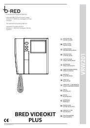
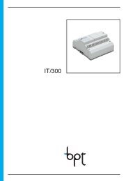
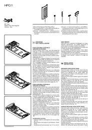
IT - INSTALLAZIONE<br />
LYNEA BASIC (YVL301)<br />
ATTENZIONE. Si raccomanda <strong>di</strong> installare il<br />
monitor in ambiente asciutto.<br />
Aprire il videocitofono come in<strong>di</strong>cato in figura 1<br />
e 2. Togliere il connettore (fig. 3) e installare il videocitofono<br />
come in<strong>di</strong>cato in figura 4, 5 e 6.<br />
Per un fissaggio ancora più stabile rimuovere il<br />
supporto cornetta con un cacciavite attraverso<br />
l’apposita feritoia (fig. 7) e fissare il videocitofono<br />
come in<strong>di</strong>cato in figura 8.<br />
Collegare (fig. 3) e rimontare il videocitofono<br />
come in<strong>di</strong>cato in figura 9.<br />
EN - INSTALLATION<br />
WARNING. It is recommended to install the<br />
monitor in a dry place.<br />
Open the video entry control as shown in figures 1<br />
and 2. Remove the connector (fig. 3) and install the<br />
video entry control as shown in figures 4, 5 and 6.<br />
For even more secure fastening, remove the receiver<br />
support with a screwdriver through the<br />
slot (fig. 7) and fasten the video entry control as<br />
shown in figure 8.<br />
Connect (fig. 3) an re-install the video entry control<br />
as shown in figure 9.<br />
DE - INSTALLATION<br />
ACHTUNG. Es wird empfohlen <strong>den</strong> Monitor<br />
an einer geschützten Stelle zu installieren.<br />
Die Videosprechanlage wie in <strong>den</strong> Abbildungen 1<br />
und 2 gezeigt, öffnen. Den Steckverbinder (Abb.<br />
3) entfernen und <strong>di</strong>e Videosprechanlage wie in<br />
<strong>den</strong> Abbildungen 4, 5 und 6 gezeigt, installieren.<br />
Für eine stabilere Befestigung <strong>di</strong>e Hörerhalterung<br />
mit einem Schraubenzieher über <strong>den</strong><br />
entsprechen<strong>den</strong> Schlitz (Abb. 7) abnehmen und<br />
<strong>di</strong>e Videosprechanlage wie in der Abbildung 8<br />
gezeigt, befestigen.<br />
Die Videosprechanlage wie in der Abbildung 9<br />
gezeigt, anschließen (Abb. 3) und wieder montieren.<br />
PHI<br />
95 mm<br />
FR - INSTALLATION<br />
ATTENTION. Le moniteur doit être installé<br />
dans une pièce séche.<br />
Ouvrir le portier vidéo comme in<strong>di</strong>qué aux figures<br />
1 et 2. Enlever le connecteur (fig. 3) et installer<br />
le portier vidéo comme in<strong>di</strong>qué aux figures 4, 5<br />
et 6.<br />
Pour fixer de manière encore plus stable, enlever<br />
le support du combiné à l’aide d’un tournevis à<br />
travers la fente prévue à cet effet (fig. 7) et fixer le<br />
portier vidéo comme in<strong>di</strong>qué à la figure 8.<br />
Raccorder (fig. 3) et remonter le portier vidéo<br />
comme in<strong>di</strong>qué à la figure 9.<br />
ES - INSTALACIÓN<br />
ATENCION. Se recomienda instalar el monitor<br />
en un ambiente seco.<br />
Abra el videoportero electrónico como se in<strong>di</strong>ca<br />
en las figuras 1 y 2. Extraiga el conector (fig. 3) e<br />
instale el videoportero electrónico como se in<strong>di</strong>ca<br />
en las figuras 4, 5 y 6.<br />
Para una fijación aún más estable, retire el soporte<br />
del auricular introduciendo un destornillador<br />
a través de la ranura (fig. 7) y fije el videoportero<br />
electrónico como se in<strong>di</strong>ca en la figura 8.<br />
Conecte (fig. 3) y vuelva a montar el videoportero<br />
electrónico como se in<strong>di</strong>ca en la figura 9.<br />
PT - INSTALAÇÃO<br />
ATENÇÃO. Se aconselha de instalar o monitor<br />
em ambiente enxuto.<br />
Abra o vídeo porteiro como in<strong>di</strong>cado na figura 1<br />
e 2. Remova o conector (fig. 3) e instale o vídeo<br />
porteiro como in<strong>di</strong>cado na figura 4, 5 e 6.<br />
Para uma fixação ainda mais estável remova o suporte<br />
do fone com uma chave de fenda através<br />
da fenda específica (fig. 7) e fixe o vídeo porteiro<br />
conforme in<strong>di</strong>cado na figura 8.<br />
Ligue (fig. 3) e monte de novo o vídeo porteiro<br />
como in<strong>di</strong>cado na figura 9.<br />
DVC/01<br />
DVC/01 ME<br />
83,5 mm<br />
503<br />
4<br />
A<br />
6<br />
2<br />
8<br />
1<br />
5<br />
7<br />
9<br />
6
LYNEABASIC<br />
M1<br />
–<br />
+<br />
SW1<br />
A<br />
INT3-4<br />
EN.AUX<br />
INT1-2<br />
B<br />
SW10<br />
SW9<br />
SW3<br />
+<br />
B<br />
+<br />
LOCAL<br />
SW8<br />
CN4<br />
M1<br />
BUS<br />
BUS<br />
LOCAL<br />
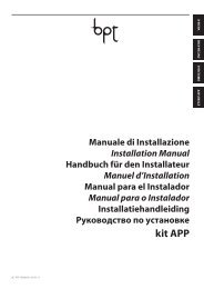
IT - MORSETTIERE EN - TERMINAL BOARDS DE - KLEMMENBRETTER<br />
Ingresso chiamata dal pianerottolo Doorbell input Rufeingang vom Treppenhaus<br />
B Ingresso linea BUS BUS line input Eingang BUS-Leitung<br />
– 14÷18 Vcc<br />
+ alimentazione locale<br />
Power supply local<br />
From 14÷18 V DC<br />
14-18VDC<br />
SW9<br />
Stromversorgung örtlich<br />
zu 14÷18 VDC<br />
OPHERA LYNEA<br />
LYNEA BASIC<br />
M1<br />
–<br />
+<br />
FR - BORNIERS ES - BORNERAS PT - RÉGUAS DE BORNES<br />
Entrée appel depuis le palier Entrada llamada desde el rellano Entrada chamada do patamar<br />
B Entrée ligne BUS Entrada línea BUS Entrada linha BUS<br />
– Alimentation local<br />
+ de 14÷18 Vcc<br />
Alimentación local<br />
de 14÷18 Vcc<br />
Alimentação local<br />
desde 14÷18 Vcc<br />
NOVA<br />
IT - FUNZIONE DEI CONNETTORI EN - FUNCTION OF CONNECTOR DE - FUNKTION DER STECKVERBINDER<br />
CN4: collegamento al monitor. CN4: connection to the monitor. CN4: Monitoranschluss.<br />
FR - FONCTION DE CONNECTEUR ES - FUNCIÓN DE CONECTORE PT - FUNÇÃO DE CONECTORE<br />
CN4: raccordement au moniteur. CN4: conexión al monitor. CN4: ligação ao monitor.<br />
MITHO<br />
IT -<br />
CARATTERISTICHE TECNICHE<br />
EN -<br />
TECHNICAL FEATURES<br />
DE -<br />
TECHNISCHE MERKMALE<br />
VAS/100.30<br />
FR -<br />
CARACTÉRISTIQUES TECHNIQUES<br />
ES -<br />
CARACTERÍSTICAS TÉCNICAS<br />
PT -<br />
CARACTERÍSTICAS TÉCNICAS<br />
Alimentazione locale-Supply voltage local-Stromversorgung örtlich-<br />
14-18 VDC<br />
Alimentation local-Alimentación local-Alimentação local<br />
Alimentazione da BUS-Power supply from BUS-Stromversorgung über BUS-Alimentation depuis BUS- 15÷20 VDC<br />
Alimentación desde BUS-Alimentação de BUS<br />
Assorbimento-Absorption-Stromaufnahme-<br />
YVL301: 520 mA max (
LYNEABASIC<br />
LYNEA BASIC LYNEA OPHERA<br />
NOVA MITHO VAS/100.30<br />
DVC/01<br />
DVC/01 ME<br />
IT - SELEZIONI EN - SELECTIONS DE - WAHLEN<br />
FR - SÉLECTIONS ES - SELECCIONES PT - SELECÇÕES<br />
SW1 (Attenuazione della chiamata)<br />
SW1 (Call attenuated)<br />
SW1 (Abschwächung des Anrufs)<br />
SW1(Atténuation de l’appel)<br />
SW1 (Atenuación de la llamada)<br />
SW1(Atenuação da chamada)<br />
SW3(Resistenza <strong>di</strong> chiusura)<br />
SW3 (Resistive load termination)<br />
SW3 (Schließwiderstand)<br />
SW3 (Résistance de fermeture)<br />
SW3 (Resistencia de cierre)<br />
SW3 (Resistência de fecho)<br />
SW8 (Selezione MASTER/SLAVE)<br />
SW8 (Selezione MASTER/SLAVE)<br />
SW8 (Selezione MASTER/SLAVE)<br />
SW8 (Selezione MASTER/SLAVE)<br />
SW8 (Selezione MASTER/SLAVE)<br />
SW8 (Selezione MASTER/SLAVE)<br />
SW9 (Selezione sorgente <strong>di</strong> alimentazione)<br />
SW9 (Selects power source)<br />
SW9 (Auswahl der Stromquelle)<br />
SW9 (Sélection source d’alimentation)<br />
SW9 (Selección de fuente de alimentación)<br />
SW9 (Selección de fuente de alimentación)<br />
SW10 (Funzione tasti e )<br />
SW10 (Operation of and keys)<br />
SW10 (Funktion Tasten und )<br />
SW10 (Fonction touches et )<br />
SW10 (Función botones y )<br />
SW10 (Função das teclas e )<br />
YKT/F<br />
XDV/304<br />
SW1<br />
SW1<br />
SW1<br />
SW3 SW3 SW3<br />
1 2 3<br />
SW8<br />
M/S<br />
MASTER<br />
SW8<br />
M/S<br />
SLAVE<br />
IT In caso <strong>di</strong> chiamata contemporanea, solo sul derivato MASTER verrà attivata la comunicazione au<strong>di</strong>o/video.<br />
EN In case of simultaneous call, the au<strong>di</strong>o/video communication will be activated on the MASTER extension<br />
only.<br />
DE Bei einem gleichzeitigen Anruf, wird <strong>di</strong>e Au<strong>di</strong>o-/Videoverbindung nur auf der Innensprechstelle MASTER<br />
aktiviert.<br />
FR En cas d’appel simultané, la communication au<strong>di</strong>o/vidéo sera activée uniquement sur le poste MASTER.<br />
ES En caso de llamada simultánea, la comunicación au<strong>di</strong>o/vídeo se activará solo en el derivado MASTER.<br />
PT No caso de chamada contemporânea, só no derivado MASTER é que será· activada a comunicação áu<strong>di</strong>o/<br />
vídeo.<br />
SW10<br />
BUS<br />
LOCAL<br />
SW9<br />
+<br />
+<br />
B<br />
M1<br />
Alimentazione separata<br />
Separate power supply<br />
Getrennte Versorgung<br />
Alimentation SW10 séparée<br />
Alimentación separada<br />
Alimentação separada<br />
SW10<br />
INTERCOM 1<br />
SW10<br />
INTERCOM 2<br />
BUS<br />
LOCAL<br />
SW9<br />
SW10<br />
SW10<br />
+<br />
+<br />
B<br />
M1<br />
INTERCOM 1<br />
INTERCOM 2<br />
INTERCOM 3<br />
INTERCOM 4<br />
Alimentazione da BUS<br />
Power supply<br />
INTERCOM<br />
from BUS<br />
1<br />
Stromversorgung über BUS<br />
INTERCOM 2<br />
Alimentation depuis BUS<br />
SW10<br />
Alimentación desde BUS<br />
Alimentação de BUS<br />
SW10<br />
INTERCOM 3<br />
INTERCOM 4<br />
IT NOTA. A cornetta agganciata in qualsiasi posizione sia il Jumper SW10 i pulsanti e funzioneranno<br />
come AUX1 e AUX2.<br />
EN NOTE. With the receiver connected, INTERCOM regardless 3 of the position AUX1<br />
SW10 of Jumper SW10, the and buttons<br />
will operate as AUX1 and AUX2.<br />
INTERCOM 4<br />
AUX2<br />
DE HINWEIS Mit eingehängtem Hörer funktionieren der Verbindungsdraht SW10 und <strong>di</strong>e Taste e als<br />
AUX1 und AUX2.<br />
FR NOTE. À combiné raccroché quelle que soit la position, soit le Jumper SW10, la touche et fonctionneront<br />
comme AUX1 et AUX2.<br />
ES AUX1<br />
NOTA. Con el auricular colgado en cualquier posición, tanto el Jumper SW10 como los botones y<br />
funcionarán como AUX1 y AUX2.<br />
AUX2<br />
PT NOTA. Com o auscultador encaixado em qualquer posição, quer o Jumper SW10, quer o botão e<br />
funcionam como AUX1 e AUX2.<br />
AUX1<br />
AUX2<br />
IT - ACCESSORI EN - ACCESSORIES DE - ZUBEHÖR<br />
a Supporto da tavolo YKT/F a Table-top mounting YKT/F a Tischmontagehalter YKT/F<br />
a<br />
FR - ACCESSOIRES ES - ACCESORIOS PT - ACESSÓRIOS<br />
a Support de table YKT/F a Soporte de sobremesa<br />
YKT/F<br />
a Suporte de mesa YKT/F<br />
8
LYNEABASIC<br />
IT - PROGRAMMAZIONE EN - PROGRAMMING DE - PROGRAMMIERUNG<br />
FR - PROGRAMMATION ES - PROGRAMACIÓN PT - PROGRAMAÇÃO<br />
y Per la programmazione della chiamata, vedere la docu<br />
mentazione dei posti esterni.<br />
y For call programming, see the entry panel documentation.<br />
a<br />
b<br />
c<br />
+<br />
A<br />
X 5<br />
d<br />
beep<br />
y Für <strong>di</strong>e Rufprogrammierung, siehe Unterlagen der Außen<br />
stationen.<br />
y Pour la programmation de l’appel, voir la documentation<br />
y Para la programación de la llamada, consulte la documen<br />
tación de las placas exteriores.<br />
y Para programar a chamada, consulte a documentação das<br />
des postes extérieurs.<br />
placas botoneiras.<br />
Ingresso in Programmazione. Sollevare la cornetta e premere per 5 volte il pulsante A entro 5 s. Un breve segnale acustico conferma l’ingresso<br />
in programmazione a.<br />
Accessing programming. Lift the receiver and press the button A 5 times within 5 s. A brief acoustic signal will confirm that programming has<br />
been accessed a.<br />
Einstieg in <strong>di</strong>e Programmierung. Den Hörer hochheben und innerhalb 5 Sek. fünf,mal <strong>di</strong>e Taste A drücken. Ein kurzer Signalton bestätigt<br />
<strong>den</strong> Einstieg in <strong>di</strong>e Programmierung a.<br />
Entrée en Programmation. Décrocher le combiné et appuyer 5 fois sur la touche A dans les 5 s. Un bref signal sonore confirme l’entrée dans la<br />
programmation a.<br />
Entrada en la modalidad de Programación Descuelgue el auricular y pulse 5 veces el botón A antes de 5 s. Una breve señal acústica<br />
confirmará que se ha entrado en la modalidad de programación a.<br />
Entrada em Programação. Levante o auscultador e aperte 5 vezes o botão A por 5 s. Um breve sinal acústico confirmará a entrada em programação<br />
a.<br />
Programmazione della melo<strong>di</strong>a associata alla chiamata dal posto esterno (1 segnale acustico). Per ascoltare in sequenza le<br />
melo<strong>di</strong>e premere il tasto b. Per selezionare la melo<strong>di</strong>a ed uscire dalla programmazione riporre la cornetta c. Per selezionare la melo<strong>di</strong>a e<br />
proseguire con la programmazione premere il tasto d.<br />
Programming the melody associated to the call from the entry panel (1 acoustic signal). To hear the melo<strong>di</strong>es in sequence, press<br />
the key b. To select the melody and exit programming, replace the receiver c. To select the melody and continue with programming, press the<br />
key d.<br />
Programmierung der Melo<strong>di</strong>e, <strong>di</strong>e mit dem Anruf von der Außenstation verknüpft ist (1 akustisches Signal). Um <strong>di</strong>e Melo<strong>di</strong>en<br />
nacheinander zu hören, <strong>di</strong>e Taste drücken b. Zum Wählen der Melo<strong>di</strong>e und Verlassen der Programmierung, <strong>den</strong> Hörer wieder auflegen<br />
c. Zum Wählen der Melo<strong>di</strong>e und fortsetzen der Programmierung, <strong>di</strong>e Taste drücken d.<br />
Programmation de la mélo<strong>di</strong>e associée à l’appel provenant du poste extérieur (1 signal sonore). Pour écouter les mélo<strong>di</strong>es en<br />
séquence, appuyer sur la touche b. Pour sélectionner la mélo<strong>di</strong>e et quitter la programmation, raccrocher le combiné c. Pour sélectionner la<br />
mélo<strong>di</strong>e et continuer la programmation, appuyer sur la touche d.<br />
Programación de la melodía asociada a la llamada desde la placa exterior (1 señal acústica). Para escuchar en secuencia las<br />
melodías, pulse el botón b. Para seleccionar la melodía y salir de la modalidad de programación, cuelgue el auricular c. Para seleccionar la<br />
melodía y proseguir con la programación, pulse el botón d.<br />
Programação da melo<strong>di</strong>a associada à chamada da placa botoneira (1 sinal acústico). Para ouvir as melo<strong>di</strong>as em sequência aperte<br />
a tecla b. Para seleccionar a melo<strong>di</strong>a e sair da programação, pouse o auscultador c. Para seleccionar a melo<strong>di</strong>a e continuar a programação,<br />
aperte a tecla d.<br />
OPHERA LYNEA<br />
LYNEA BASIC<br />
NOVA<br />
e<br />
f<br />
h<br />
i<br />
j<br />
g<br />
Programmazione della melo<strong>di</strong>a associata alla chiamata dal pianerottolo (2 segnali acustici). Per questo tipo <strong>di</strong> programmazione<br />
e f g procedere come la “Programmazione della melo<strong>di</strong>a associata alla chiamata dal posto esterno” prece<strong>den</strong>temente descritta.<br />
Programming the melody associated with the doorbell (2 acoustic signals). For this type of programming e f g proceed as<br />
previously described for “Programming the melody associated to the call from the entry panel”.<br />
Programmierung der Melo<strong>di</strong>e, <strong>di</strong>e mit dem Anruf vom Treppenhaus verknüpft ist (2 akustische Signale). Für <strong>di</strong>ese Programmierungsart<br />
e f g.wie bei der zuvor beschriebenen “Programmierung der Melo<strong>di</strong>e, <strong>di</strong>e mit dem Anruf von der Außenstation verknüpft<br />
ist” vorgehen.<br />
Programmation de la mélo<strong>di</strong>e associée à l’appel provenant du palier (2 signaux sonores). Pour ce type de programmation e f<br />
g procéder comme pour la “Programmation de la mélo<strong>di</strong>e associée à l’appel provenant du poste extérieur” décrite précédemment.<br />
Programación de la melodía asociada a la llamada desde el rellano (2 señales acústicas). Para este tipo de programación<br />
e f g siga los mismos pasos que para la “Programación de la melodía asociada a la llamada desde la placa exterior” descrita previamente.<br />
Programação da melo<strong>di</strong>a associada à chamada do patamar (2 sinais acústicos). Para este tipo de programação e f g continue<br />
como para a “Programação da melo<strong>di</strong>a associada à chamada da placa botoneira” descrita anteriormente.<br />
Programmazione del numero <strong>di</strong> squilli <strong>di</strong> chiamata (3 segnali acustici). Premere il tasto tante volte quanti sono gli squilli che si<br />
è scelto per la chiamata (da 1 a 6 squilli) h. Dopo 3 s dall’ultima pressione del tasto verrà riprodotta la chiamata selezionata per il numero <strong>di</strong> squilli<br />
prescelto. Per salvare le impostazioni riporre la cornetta j altrimenti premere il pulsante apriporta i per ritornare nuovamente alla programmazione<br />
della melo<strong>di</strong>a <strong>di</strong> chiamata dal posto esterno.<br />
Programming the number of call rings (3 acoustic signals). Press the key the number of times equal to the rings selected for the call (1<br />
to 6 rings) h. 3 s after the key is pressed the last time, the call selected for the selected number of rings will be will be reproduced. To save the new<br />
setting, hang up j; otherwise, press the door lock release button ( ) i to enter the entry panel call melody programming procedure again.<br />
Programmierung der Anzahl der Ruftöne (3 akustische Signale). Die Taste so oft drücken, wie Ruftöne für <strong>den</strong> Anruf gewünscht<br />
wer<strong>den</strong> (1 bis 6 Ruftöne) h. 3 s nach dem letzten Drücken der Taste wird der gewählte Anruf mit der Anzahl der festgelegten Ruftöne wiederholt.<br />
Zur Speicherung <strong>di</strong>eser Neueinstellung j Hörer wieder auflegen. Andernfalls Türöffnertaste drücken ( ) i, um erneut auf <strong>di</strong>e Programmierung<br />
der Melo<strong>di</strong>e des Anrufs von der Außenstation überzugehen.<br />
Programmation du nombre de sonneries d’appel (3 signaux sonores). Appuyer sur la touche autant de fois que le nombre de sonneries<br />
que l’on a choisi pour l’appel (de 1 à 6 sonneries) h. 3 s après la dernière pression sur la touche, l’appel sélectionné pour le nombre de sonneries<br />
choisi sera effectué. Pour enregistrer raccrocher j; sinon, appuyer sur la touche ouvre-porte ( ) i pour accéder de nouveau à la programmation<br />
de la mélo<strong>di</strong>e d’appel depuis le poste extérieur.<br />
Programación del número de tonos de llamada (3 señales acústicas). Pulse el botón un número de veces igual a los tonos que<br />
se desean para la llamada (de 1 a 6 tonos) h. Pasados 3 s desde la última vez que se pulse el botón, se reproducirá la llamada seleccionada con<br />
el número de tonos elegido. Para memorizar la nueva configuración basta colgar el auricular j, sino pulsar el botón abrepuerta ( ) i para<br />
acceder de nuevo a la programación de la melodía de llamada desde la placa exterior.<br />
Programação do número de toques de chamada (3 sinais acústicos). Aperte a tecla tantas vezes quantas desejar para o número de<br />
toques da chamada (de 1 a 6 toques) h. Após 3 s, a partir da última vez que apertou a tecla, será reproduzida a chamada seleccionada para o<br />
número de toques desejado. Para salvar a nova regulação pousar o auscultador j, <strong>di</strong>ferentemente premir o botão de abertura da porta ( ) i<br />
para ter acesso novamente à programação da melo<strong>di</strong>a de chamada da placa botoneira.<br />
MITHO<br />
VAS/100.30<br />
DVC/01<br />
DVC/01 ME<br />
9
LYNEA<br />
LYNEA BASIC LYNEA OPHERA<br />
NOVA MITHO VAS/100.30<br />
83,5 mm<br />
PHI<br />
503<br />
A<br />
95 mm<br />
1<br />
2<br />
3<br />
IT - INSTALLAZIONE<br />
ATTENZIONE. Si raccomanda <strong>di</strong> installare il<br />
monitor in ambiente asciutto.<br />
Il supporto da parete può essere installato seguendo<br />
le in<strong>di</strong>cazioni delle fig. 1÷5.<br />
Montare il modulo monitor sul supporto da parete<br />
come in<strong>di</strong>cato nelle figure 6 e 7.<br />
Per togliere il modulo monitor agire con cacciavite<br />
attraverso la feritoia sul mobile (fig. 8).<br />
Per rimuovere il mobile YKP, agire con un cacciavite<br />
attraverso l’apposita feritoia (fig. 4).<br />
EN - INSTALLATION<br />
WARNING. It is recommended to install the<br />
monitor in a dry place.<br />
The wall mounting can be installed following the<br />
instructions in figures 1-5.<br />
Fit the monitor module on the wall mounting as<br />
illustrated in figures 6 and 7.<br />
To remove the monitor module, prise it off by<br />
inserting a screwdriver in the slot in the housing<br />
(fig. 8).<br />
To remove the YKP cover, use a screwdriver inserted<br />
in the slot (fig. 4).<br />
DE - INSTALLATION<br />
ACHTUNG. Es wird empfohlen <strong>den</strong> Monitor<br />
an einer geschützten Stelle zu installieren.<br />
Die Wandhalterung kann gemäß nachstehen<strong>den</strong><br />
Abb. 1÷5 erfolgen.<br />
Monitormodul auf <strong>den</strong> Wandhalter positionieren<br />
und dabei <strong>den</strong> Abb. 6 und 7 entsprechend vorgehen.<br />
Bei der Abnahme des Monitormoduls mit einem<br />
Schraubenzieher im Gehäuseschlitz einwirken<br />
(Abb. 8).<br />
Zum Entfernen des Deckels YKP, einen Schraubenzieher<br />
in <strong>den</strong> entsprechen<strong>den</strong> Schlitz stecken<br />
(Abb. 4).<br />
LYNEA (YV-YVC)<br />
FR - INSTALLATION<br />
ATTENTION. Le moniteur doit être installé<br />
dans une pièce séche.<br />
Le support mural peut être installé en suivant les<br />
instructions des figures 1÷5. Monter le module<br />
moniteur sur le support mural comme in<strong>di</strong>qué<br />
aux figures 6 et 7. Pour ôter le module moniteur,<br />
passer un tournevis à travers la fente sur le meuble<br />
(fig. 8).<br />
Pour enlever le couvercle YKP, agir avec un<br />
tournevis à travers la fente prévue à cet effet (fig.<br />
4).<br />
ES - INSTALACIÓN<br />
ATENCION. Se recomienda instalar el monitor<br />
en un ambiente seco.<br />
El soporte mural se puede instalar siguiendo las<br />
in<strong>di</strong>caciones de las fig. 1÷5. Montar el módulo<br />
monitor en el soporte mural como mostrado en<br />
las figuras 6 y 7.<br />
Para quitar el módulo monitor actuar con un destornillador<br />
a través de la ranura en la caja (fig. 8).<br />
Para retirar la tapa YKP, utilice un destornillador a<br />
través de la rejilla correspon<strong>di</strong>ente (fig. 4).<br />
PT - INSTALAÇÃO<br />
ATENÇÃO. Se aconselha de instalar o monitor<br />
em ambiente enxuto.<br />
O suporte de parede pode ser instalado seguindo<br />
as in<strong>di</strong>cações das fig. 1÷5. Montar o<br />
módulo monitor no suporte de parede como<br />
in<strong>di</strong>cado nas figuras 6 e 7.<br />
Para tirar o módulo monitor agir com chave de<br />
parafuso através da abertura do móvel (fig. 8).<br />
Para remover a tampa YKP, agir com uma chave<br />
através da fenda apropriada (fig. 4).<br />
DVC/01<br />
DVC/01 ME<br />
4<br />
2<br />
6<br />
1<br />
2<br />
1<br />
5<br />
7<br />
8<br />
10
LYNEA<br />
M1<br />
M2<br />
M1<br />
–<br />
+<br />
SW1<br />
M2<br />
A<br />
B<br />
CN1<br />
CN2<br />
A<br />
B<br />
CN3<br />
A/B<br />
SW9<br />
SW3<br />
+<br />
B<br />
+<br />
LOCAL<br />
SW8<br />
CN4<br />
M1<br />
BUS<br />
BUS<br />
LOCAL<br />
IT - MORSETTIERE EN - TERMINAL BOARDS DE - KLEMMENBRETTER<br />
Chiamata pianerottolo Doorbell Ruf vom Treppenhaus<br />
B Ingresso linea BUS BUS line input Eingang BUS-Leitung<br />
– da 14÷18 Vcc<br />
+ alimentazione locale<br />
–<br />
+<br />
Power supply local<br />
From 14÷18 V DC<br />
14-18VDC<br />
SW9<br />
Stromversorgung örtlich<br />
zu 14÷18 VDC<br />
collegamento per l’altoparlante YAL connection for YAL loudspeake raccordement pour le haut-parleur YAL<br />
FR - BORNIERS ES - BORNERAS PT - RÉGUAS DE BORNES<br />
Appel depuis le palier Llamada desde el rellano Chamada do patamar<br />
B Entrée ligne BUS Entrada línea BUS Entrada linha BUS<br />
– Alimentation local<br />
+ de 14÷18 Vcc<br />
Alimentación local<br />
de 14÷18 Vcc<br />
Alimentação local<br />
desde 14÷18 Vcc<br />
OPHERA LYNEA<br />
LYNEA BASIC<br />
NOVA<br />
M2<br />
conexión para el altavoz YAL .conexión para el altavoz YAL ligação para o altifalante YAL<br />
IT - FUNZIONE DEI CONNETTORI EN - FUNCTION OF CONNECTORS DE - FUNKTION DER STECKVERBINDER<br />
CN1 collegando a questo connettore l’accessorio<br />
YP3 vengono aggiunti 3 tasti per chiamate intercomunicanti<br />
(1-3) o 3 coman<strong>di</strong> ausiliari aggiuntivi<br />
(3-5).<br />
CN1 when the accessory YP3 is connected to<br />
this connector, 3 keys are added for intercom<br />
calls (1-3) or 3 ad<strong>di</strong>tional auxiliary controls (3-5).<br />
CN1 wenn man das Zubehör YP3 an <strong>di</strong>esen<br />
Steckverbinder anschließt, erhält man 3 weitere<br />
Tasten für Intercom-Anrufe (1-3) oder 3 Zusatzsteuerungen<br />
(3-5).<br />
CN2 collegando a questo connettore l’accessorio<br />
YP3 vengono aggiunti ulteriori 3 tasti per chiamate<br />
intercomunicanti (4-6) o 3 coman<strong>di</strong> ausiliari aggiuntivi<br />
(6-8).<br />
CN2 when the accessory YP3 is connected to<br />
this connector, 3 ad<strong>di</strong>tional keys are added for<br />
intercom calls (4-6) or 3 ad<strong>di</strong>tional auxiliary controls<br />
(6-8).<br />
CN2 wenn man das Zubehör YP3 an <strong>di</strong>esen<br />
Steckverbinder anschließt, erhält man 3 weitere<br />
Tasten für Intercom-Anrufe (4-6) oder 3 Zusatzsteuerungen<br />
(6-8).<br />
CN3 collegamento all’accessorio YPL CN3 connection to the accessory YPL CN3 Anschluss an Zubehör YPL<br />
CN4: collegamento al monitor YV- YVC CN4: connection to the monitor YV- YVC CN4: Anschluss an Monitor YV- YVC<br />
FR - FONCTION DES CONNECTEURS ES - FUNCIÓN DE LOS CONECTORES PT - FUNÇÃO DOS CONECTORES<br />
CN1 en raccordant à ce connecteur l’accessoire YP3,<br />
on ajoute 3 touches pour des appels à intercommunication<br />
(1-3) ou 3 commandes auxiliaires supplémentaires<br />
(3-5).<br />
CN1 conectando a este conector el accesorio<br />
YP3 se aña<strong>den</strong> 3 botones para llamadas intercomunicantes<br />
(1-3) o 3 mandos auxiliares a<strong>di</strong>cionales<br />
(3-5).<br />
CN1 ao ligar o acessório YP3 a este conector,<br />
serão a<strong>di</strong>cionadas 3 teclas para chamadas intercomunicantes<br />
(1-3) ou 3 comandos auxiliares<br />
a<strong>di</strong>cionais (3-5).<br />
CN2 en raccordant à ce connecteur l’accessoire YP3,<br />
on ajoute 3 touches pour des appels à intercommunication<br />
(4-6) ou 3 commandes auxiliaires supplémentaires<br />
(6-8).<br />
CN2 conectando a este conector el accesorio<br />
YP3 se aña<strong>den</strong> otros 3 botones para llamadas<br />
intercomunicantes (4-6) o 3 mandos auxiliares<br />
a<strong>di</strong>cionales (6-8).<br />
CN2 ao ligar o acessório YP3 a este conector,<br />
serão a<strong>di</strong>cionadas outras 3 teclas para chamadas<br />
intercomunicantes (4-6) ou 3 comandos auxiliares<br />
a<strong>di</strong>cionais (6-8).<br />
CN3 connexion d’accessoires YPL CN3 conexión de accesorios YPL CN3 conexão de acessórios YPL<br />
CN4: raccordement au moniteur YV- YVC CN4: conexión al monitor YV- YVC CN4: ligação ao monitor YV- YVC<br />
MITHO<br />
VAS/100.30<br />
DVC/01<br />
DVC/01 ME<br />
11
LYNEA<br />
LYNEA BASIC LYNEA OPHERA<br />
NOVA MITHO VAS/100.30<br />
DVC/01<br />
DVC/01 ME<br />
IT - SELEZIONI EN - SELECTIONS DE - WAHLEN<br />
FR - SÉLECTIONS ES - SELECCIONES PT - SELECÇÕES<br />
SW1 (Attenuazione della chiamata)<br />
SW1 (Call attenuated)<br />
SW1 (Abschwächung des Anrufs)<br />
SW1(Atténuation de l’appel)<br />
SW1 (Atenuación de la llamada)<br />
SW1(Atenuação da chamada)<br />
SW3(Resistenza <strong>di</strong> chiusura)<br />
SW3 (Resistive load termination)<br />
SW3 (Schließwiderstand)<br />
SW3 (Résistance de fermeture)<br />
SW3 (Resistencia de cierre)<br />
SW3 (Resistência de fecho)<br />
SW8 Selezione MASTER/SLAVE<br />
SW8 MASTER/SLAVE Selects<br />
SW8 Auswahl MASTER/SLAVE<br />
SW8 Sélection MASTER/SLAVE<br />
SW8 Selección MASTER/SLAVE<br />
SW8 Selección MASTER/SLAVE<br />
SW9 (Selezione sorgente <strong>di</strong> alimentazione)<br />
SW9 (Selects power source)<br />
SW9 (Auswahl der Stromquelle)<br />
SW9 (Sélection source d’alimentation)<br />
SW9 (Selección de fuente de alimentación)<br />
SW9 (Selección de fuente de alimentación)<br />
IT -<br />
FR -<br />
CARATTERISTICHE TECNICHE<br />
CARACTÉRISTIQUES TECHNIQUES<br />
EN -<br />
ES -<br />
XDV/304<br />
SW1<br />
SW1<br />
SW1<br />
SW3 SW3 SW3<br />
1 2 3<br />
BUS<br />
SW8<br />
M/S<br />
LOCAL<br />
BUS<br />
LOCAL<br />
Alimentazione locale-Supply voltage local-Stromversorgung örtlich-<br />
Alimentation local-Alimentación local-Alimentação local<br />
Alimentazione da BUS-Power supply from BUS-Stromversorgung über BUS-<br />
Alimentation depuis BUS-Alimentación desde BUS-Alimentação de BUS<br />
Assorbimento-Absorption-Stromaufnahme-Absorption-Consumo-Consumo<br />
Dimensioni-Dimensions-Maße-Dimensions-Dimensiones-Dimensões<br />
Temperatura <strong>di</strong> stoccaggio-Storage temperature-Lagerungstemperatur<br />
Température de stockage-Temperatura de almacenamiento-Temperatura de armazenagem<br />
SW9<br />
SW9<br />
MASTER<br />
SW8<br />
M/S<br />
B<br />
+<br />
M1<br />
B<br />
+<br />
M1<br />
SLAVE<br />
TECHNICAL FEATURES<br />
CARACTERÍSTICAS TÉCNICAS<br />
Alimentazione separata - Separate power supply<br />
Getrennte Versorgung - Alimentation séparée<br />
Alimentación separada - Alimentação separada<br />
Alimentazione da BUS - Power supply from BUS<br />
Stromversorgung über BUS - Alimentation depuis BUS<br />
Alimentación desde BUS - Alimentação de BUS<br />
14-18 VDC<br />
15÷20 VDC<br />
YV: 520 mA max (
LYNEA<br />
IT - PROGRAMMAZIONE EN - PROGRAMMING DE - PROGRAMMIERUNG<br />
FR - PROGRAMMATION ES - PROGRAMACIÓN PT - PROGRAMAÇÃO<br />
y Per la programmazione della chiamata, vedere la docu<br />
mentazione dei posti esterni.<br />
y For call programming, see the entry panel documentation.<br />
a<br />
b<br />
c<br />
+<br />
A<br />
X 5<br />
d<br />
beep<br />
y Für <strong>di</strong>e Rufprogrammierung, siehe Unterlagen der Außen<br />
stationen.<br />
y Pour la programmation de l’appel, voir la documentation<br />
des postes extérieurs.<br />
y Para la programación de la llamada, consulte la documen<br />
tación de las placas exteriores.<br />
y Para programar a chamada, consulte a documentação das<br />
placas botoneiras.<br />
Ingresso in Programmazione. Sollevare la cornetta e premere per 5 volte il pulsante A entro 5 s. Un breve segnale acustico conferma l’ingresso<br />
in programmazione a.<br />
Accessing programming. Lift the receiver and press the button A 5 times within 5 s. A brief acoustic signal will confirm that programming has<br />
been accessed a.<br />
Einstieg in <strong>di</strong>e Programmierung. Den Hörer hochheben und innerhalb 5 Sek. fünf,mal <strong>di</strong>e Taste A drücken. Ein kurzer Signalton bestätigt<br />
<strong>den</strong> Einstieg in <strong>di</strong>e Programmierung a.<br />
Entrée en Programmation. Décrocher le combiné et appuyer 5 fois sur la touche A dans les 5 s. Un bref signal sonore confirme l’entrée dans la<br />
programmation a.<br />
Entrada en la modalidad de Programación Descuelgue el auricular y pulse 5 veces el botón A antes de 5 s. Una breve señal acústica<br />
confirmará que se ha entrado en la modalidad de programación a.<br />
Entrada em Programação. Levante o auscultador e aperte 5 vezes o botão A por 5 s. Um breve sinal acústico confirmará a entrada em programação<br />
a.<br />
Programmazione della melo<strong>di</strong>a associata alla chiamata dal posto esterno (1 segnale acustico). Per ascoltare in sequenza le<br />
melo<strong>di</strong>e premere il tasto b. Per selezionare la melo<strong>di</strong>a ed uscire dalla programmazione riporre la cornetta c. Per selezionare la melo<strong>di</strong>a e<br />
proseguire con la programmazione premere il tasto d.<br />
Programming the melody associated to the call from the entry panel (1 acoustic signal). To hear the melo<strong>di</strong>es in sequence, press<br />
the key b. To select the melody and exit programming, replace the receiver c. To select the melody and continue with programming, press the<br />
key d.<br />
Programmierung der Melo<strong>di</strong>e, <strong>di</strong>e mit dem Anruf von der Außenstation verknüpft ist (1 akustisches Signal). Um <strong>di</strong>e Melo<strong>di</strong>en<br />
nacheinander zu hören, <strong>di</strong>e Taste drücken b. Zum Wählen der Melo<strong>di</strong>e und Verlassen der Programmierung, <strong>den</strong> Hörer wieder auflegen<br />
c. Zum Wählen der Melo<strong>di</strong>e und fortsetzen der Programmierung, <strong>di</strong>e Taste drücken d.<br />
Programmation de la mélo<strong>di</strong>e associée à l’appel provenant du poste extérieur (1 signal sonore). Pour écouter les mélo<strong>di</strong>es en<br />
séquence, appuyer sur la touche b. Pour sélectionner la mélo<strong>di</strong>e et quitter la programmation, raccrocher le combiné c. Pour sélectionner la<br />
mélo<strong>di</strong>e et continuer la programmation, appuyer sur la touche d.<br />
Programación de la melodía asociada a la llamada desde la placa exterior (1 señal acústica). Para escuchar en secuencia las<br />
melodías, pulse el botón b. Para seleccionar la melodía y salir de la modalidad de programación, cuelgue el auricular c. Para seleccionar la<br />
melodía y proseguir con la programación, pulse el botón d.<br />
Programação da melo<strong>di</strong>a associada à chamada da placa botoneira (1 sinal acústico). Para ouvir as melo<strong>di</strong>as em sequência aperte<br />
a tecla b. Para seleccionar a melo<strong>di</strong>a e sair da programação, pouse o auscultador c. Para seleccionar a melo<strong>di</strong>a e continuar a programação,<br />
aperte a tecla d.<br />
OPHERA LYNEA<br />
LYNEA BASIC<br />
NOVA<br />
e<br />
f<br />
h<br />
i<br />
j<br />
g<br />
Programmazione della melo<strong>di</strong>a associata alla chiamata dal pianerottolo (2 segnali acustici). Per questo tipo <strong>di</strong> programmazione<br />
e f g procedere come la “Programmazione della melo<strong>di</strong>a associata alla chiamata dal posto esterno” prece<strong>den</strong>temente descritta.<br />
Programming the melody associated with the doorbell (2 acoustic signals). For this type of programming e f g proceed as<br />
previously described for “Programming the melody associated to the call from the entry panel”.<br />
Programmierung der Melo<strong>di</strong>e, <strong>di</strong>e mit dem Anruf vom Treppenhaus verknüpft ist (2 akustische Signale). Für <strong>di</strong>ese Programmierungsart<br />
e f g.wie bei der zuvor beschriebenen “Programmierung der Melo<strong>di</strong>e, <strong>di</strong>e mit dem Anruf von der Außenstation verknüpft<br />
ist” vorgehen.<br />
Programmation de la mélo<strong>di</strong>e associée à l’appel provenant du palier (2 signaux sonores). Pour ce type de programmation e f<br />
g procéder comme pour la “Programmation de la mélo<strong>di</strong>e associée à l’appel provenant du poste extérieur” décrite précédemment.<br />
Programación de la melodía asociada a la llamada desde el rellano (2 señales acústicas). Para este tipo de programación<br />
e f g siga los mismos pasos que para la “Programación de la melodía asociada a la llamada desde la placa exterior” descrita previamente.<br />
Programação da melo<strong>di</strong>a associada à chamada do patamar (2 sinais acústicos). Para este tipo de programação e f g continue<br />
como para a “Programação da melo<strong>di</strong>a associada à chamada da placa botoneira” descrita anteriormente.<br />
Programmazione del numero <strong>di</strong> squilli <strong>di</strong> chiamata (3 segnali acustici). Premere il tasto tante volte quanti sono gli squilli che si<br />
è scelto per la chiamata (da 1 a 6 squilli) h. Dopo 3 s dall’ultima pressione del tasto verrà riprodotta la chiamata selezionata per il numero <strong>di</strong> squilli<br />
prescelto. Per salvare le impostazioni riporre la cornetta j altrimenti premere il pulsante apriporta i per ritornare nuovamente alla programmazione<br />
della melo<strong>di</strong>a <strong>di</strong> chiamata dal posto esterno.<br />
Programming the number of call rings (3 acoustic signals). Press the key the number of times equal to the rings selected for the call (1<br />
to 6 rings) h. 3 s after the key is pressed the last time, the call selected for the selected number of rings will be will be reproduced. To save the new<br />
setting, hang up j; otherwise, press the door lock release button ( ) i to enter the entry panel call melody programming procedure again.<br />
Programmierung der Anzahl der Ruftöne (3 akustische Signale). Die Taste so oft drücken, wie Ruftöne für <strong>den</strong> Anruf gewünscht<br />
wer<strong>den</strong> (1 bis 6 Ruftöne) h. 3 s nach dem letzten Drücken der Taste wird der gewählte Anruf mit der Anzahl der festgelegten Ruftöne wiederholt.<br />
Zur Speicherung <strong>di</strong>eser Neueinstellung j Hörer wieder auflegen. Andernfalls Türöffnertaste drücken ( ) i, um erneut auf <strong>di</strong>e Programmierung<br />
der Melo<strong>di</strong>e des Anrufs von der Außenstation überzugehen.<br />
Programmation du nombre de sonneries d’appel (3 signaux sonores). Appuyer sur la touche autant de fois que le nombre de sonneries<br />
que l’on a choisi pour l’appel (de 1 à 6 sonneries) h. 3 s après la dernière pression sur la touche, l’appel sélectionné pour le nombre de sonneries<br />
choisi sera effectué. Pour enregistrer raccrocher j; sinon, appuyer sur la touche ouvre-porte ( ) i pour accéder de nouveau à la programmation<br />
de la mélo<strong>di</strong>e d’appel depuis le poste extérieur.<br />
Programación del número de tonos de llamada (3 señales acústicas). Pulse el botón un número de veces igual a los tonos que<br />
se desean para la llamada (de 1 a 6 tonos) h. Pasados 3 s desde la última vez que se pulse el botón, se reproducirá la llamada seleccionada con<br />
el número de tonos elegido. Para memorizar la nueva configuración basta colgar el auricular j, sino pulsar el botón abrepuerta ( ) i para<br />
acceder de nuevo a la programación de la melodía de llamada desde la placa exterior.<br />
Programação do número de toques de chamada (3 sinais acústicos). Aperte a tecla tantas vezes quantas desejar para o número de<br />
toques da chamada (de 1 a 6 toques) h. Após 3 s, a partir da última vez que apertou a tecla, será reproduzida a chamada seleccionada para o<br />
número de toques desejado. Para salvar a nova regulação pousar o auscultador j, <strong>di</strong>ferentemente premir o botão de abertura da porta ( ) i<br />
para ter acesso novamente à programação da melo<strong>di</strong>a de chamada da placa botoneira.<br />
MITHO<br />
VAS/100.30<br />
DVC/01<br />
DVC/01 ME<br />
13
OPHERA<br />
LYNEA BASIC LYNEA OPHERA<br />
NOVA MITHO VAS/100.30<br />
DVC/01<br />
DVC/01 ME<br />
1<br />
2<br />
1<br />
2<br />
Ø10mm<br />
A<br />
B<br />
3<br />
1<br />
2<br />
3<br />
4<br />
5<br />
IT - INSTALLAZIONE<br />
ATTENZIONE. Si raccomanda <strong>di</strong> installare il<br />
monitor in ambiente asciutto.<br />
Scatola incasso PHI<br />
La scatola può essere installata sia a muro che<br />
su pareti in cartongesso ad un’altezza adeguata<br />
all’utente rispettando l’in<strong>di</strong>cazione ALTO in<strong>di</strong>cata<br />
sul fondo della scatola d’incasso.<br />
- Dimensioni: 130x114x53,5 mm.<br />
<strong>Installazione</strong> a muro<br />
La scatola incasso va murata a filo muro munita<br />
della protezione in dotazione (fig. 2) ricavata<br />
nell’interno imballo (fig. 1).<br />
<strong>Installazione</strong> su pareti in cartongesso<br />
Premere la scatola sulla parete per ricavare i 4<br />
punti <strong>di</strong> riferimento ed effettuare i fori da 10 mm<br />
<strong>di</strong> <strong>di</strong>ametro (fig. 3).<br />
Tagliare il cartongesso per ricavare il foro <strong>di</strong> inserimento<br />
della scatola.<br />
Eliminare le 3 alette in<strong>di</strong>cate in figura 4.<br />
Inserire nella scatola la parte superiore A dei<br />
morsetti <strong>di</strong> fissaggio lasciando libera la parte inferiore<br />
B (fig. 5).<br />
Introdurre nel foro la scatola incasso e applicare<br />
la parte inferiore B (fig. 6).<br />
Bloccare la scatola alla parete utilizzando le viti in<br />
dotazione (fig. 7).<br />
Qualora lo spessore della parete sia maggiore <strong>di</strong><br />
2 cm è necessario separare le due parti dei morsetti<br />
<strong>di</strong> fissaggio posizionando la parte inferiore B<br />
come in<strong>di</strong>cato in figura 8.<br />
<strong>Installazione</strong> accessorio intercomunicante<br />
L’accessorio pulsanti in dotazione permette <strong>di</strong><br />
trasformare il videocitofono in apparecchio intercomunicante.<br />
Per applicare l’accessorio pulsanti togliere la cover<br />
sinistra e svitare le due viti (fig. 9).<br />
Inserire l’accessorio intercomunicante, avvitare le<br />
due viti e inserire la cover (fig. 10).<br />
EN - INSTALLATION<br />
WARNING. It is recommended to install the<br />
monitor in a dry place.<br />
PHI embed<strong>di</strong>ng box<br />
The embed<strong>di</strong>ng box can be installed in either<br />
masonry or plasterboard walls at a height that is<br />
suitable for the user.<br />
Make sure the UP in<strong>di</strong>cation is facing the right way<br />
in<strong>di</strong>cated on the bottom of the embed<strong>di</strong>ng box.<br />
- Dimensions: 130x114x53,5 mm.<br />
Masonry wall installation<br />
The embed<strong>di</strong>ng box should be installed flush with<br />
the wall, and equipped with the provided protection<br />
(fig. 2) to be found in the packaging (fig. 1).<br />
<strong>Installation</strong> on plasterboard walls<br />
Press the box against the wall to get four reference<br />
points where the holes with a 10 mm <strong>di</strong>ameter<br />
will be made (fig. 3).<br />
Cut the plasterboard to obtain the hole where<br />
the box will be inserted.<br />
Remove the three tabs as shown in figure 4.<br />
Insert the upper part A of the fastening clamps<br />
into the box, leaving the lower part B free (fig. 5).<br />
Place the embed<strong>di</strong>ng box into the hole and then<br />
apply the lower part B (fig. 6).<br />
Secure the box to the wall with the screws provided<br />
(fig. 7).<br />
OPHERA-OPHERA/B<br />
If the wall is more than 2 cm thick, the two parts<br />
of the fastening clamps will need to be separated,<br />
positioning the lower part B as shown in<br />
figure 8.<br />
<strong>Installation</strong> of intercom accessories<br />
The button accessory provided lets the video<br />
handset change to an intercommunicating appliance.<br />
To apply the button accessory, remove the left<br />
cover and unscrew the two screws (fig. 9).<br />
Insert the intercommunicating accessory, tighten<br />
the two screws and insert the cover (fig. 10).<br />
DE - INSTALLATION<br />
ACHTUNG. Es wird empfohlen <strong>den</strong> Monitor<br />
an einer geschützten Stelle zu installieren.<br />
UP-Kasten PHI<br />
Der UP-Kasten kann mit der beiliegen<strong>den</strong><br />
Schutz-vorrichtung und unter Beachtung der<br />
Schrift OBEN, in einer des benutzers angepassten<br />
Höhe in <strong>di</strong>e Mauer einbauen <strong>di</strong>e sich auf<br />
dem Bo<strong>den</strong> der UP-Kasten befindet.<br />
- Abmessungen: 130x114x53,5 mm.<br />
Mauerinstallation<br />
Der UP-Kasten wird bün<strong>di</strong>g mit der Wand und<br />
mit der beiliegen<strong>den</strong> Schutzvorrichtung (Abb.<br />
2) <strong>di</strong>e der internen Verpackung beiliegt (Abb. 1),<br />
gemauert.<br />
<strong>Installation</strong> in Gipskartonwän<strong>den</strong><br />
Der UP-Kasten an <strong>di</strong>e Wand drücken, um <strong>di</strong>e 4<br />
Ansatzpunkte für <strong>di</strong>e Bohrungen mit Durchmesser<br />
10 mm zu erhalten (Abb. 3).<br />
Den Gipskarton zum Einsatz des Gehäuses aufschnei<strong>den</strong>.<br />
Die 3 in der Abbildung 4 gezeigten Flügel beseitigen.<br />
In <strong>den</strong> oberen Gehäuseteil A <strong>di</strong>e Befestigungsklemmen<br />
einsetzen, dabei <strong>den</strong> unteren<br />
Teil B freilassen (Abb. 5).<br />
Der Up-Kasten in <strong>di</strong>e Öffnung einsetzen und <strong>den</strong><br />
unteren Teil B anbringen (Abb. 6).<br />
Mit <strong>den</strong> beiliegen<strong>den</strong> Schrauben, der UP-Kasten<br />
an der Wand befestigen (Abb. 7).<br />
Falls <strong>di</strong>e Wandstärke mehr als 2 cm beträgt, müssen<br />
<strong>di</strong>e zwei Teile der Befestigungklemmen getrennt<br />
und der untere Teil B wie in Abbildung 8<br />
gezeigt, positioniert wer<strong>den</strong>.<br />
<strong>Installation</strong> Intercom-Zubehör<br />
Den beiliegende Zusatz ermöglicht <strong>di</strong>e Umwandlung<br />
des Videosprechgerätes in ein Intercom-Gerät.<br />
Um <strong>den</strong> Zusatz-Tasten einzubauen, sind <strong>di</strong>e linke<br />
Abdeckung abzunehmen und <strong>di</strong>e zwei Schrauben<br />
herauszudrehen (Abb. 9).<br />
Das Intercom-Zubehör einbauen, <strong>di</strong>e zwei<br />
Schrauben eindrehen und <strong>di</strong>e Abdeckung anbringen<br />
(Abb. 10).<br />
FR - INSTALLATION<br />
ATTENTION. Le moniteur doit être installé<br />
dans une pièce séche.<br />
Boitîer d’encastrément PHI<br />
Le boîtier peut être installé soit sur le mur que sur<br />
des cloisons en placoplâtre, à une hauteur adéquate<br />
pour l’utilisateur, en respectant l’in<strong>di</strong>cation HAUT in<strong>di</strong>quée<br />
sur le fond du boîtier d’encastrement.<br />
- Dimensions: 130x114x53,5 mm.<br />
<strong>Installation</strong> au mur<br />
Le boîtier à encastrer doit être installé au ras du<br />
14
OPHERA<br />
3<br />
CLIK!<br />
1<br />
2<br />
6<br />
7<br />
mur et muni de la protection en dotation (fig. 2)<br />
comprise dans l’emballage (fig. 1).<br />
<strong>Installation</strong> sur mur en placoplâtre<br />
Placer le boîtier sur le mur afin de prendre les 4<br />
points de repère pour effectuer les trous de 10<br />
mm de <strong>di</strong>amètre (fig. 3).<br />
Découper le placoplâtre pour obtenir l’espace<br />
nécessaire à l’installation du boîtier.<br />
Éliminer les 3 ailettes in<strong>di</strong>quées figure 4.<br />
Insérer la partie supérieure A des étaux de fixation<br />
dans le boîtier en laissant libre la partie inférieure<br />
B (fig. 5).<br />
Introduire le boîtier dans cet espace et appliquer<br />
la partie inférieure B (fig. 6).<br />
Bloquer le boîtier sur le mur en utilisant les vis en<br />
dotation (fig. 7).<br />
Si l’épaisseur du mur est supérieure à 2 cm, il faut<br />
séparer les deux parties des étaux de fixation, en<br />
positionnant la partie inférieure B comme in<strong>di</strong>qué<br />
figure 8.<br />
<strong>Installation</strong> de l’accessoire d’intercommunication<br />
L’accessoire à touches fourni permet de transformer<br />
le portier vidéo en un appareil à intercommunication.<br />
Pour appliquer l’accessoire à touches enlever le<br />
cache gauche et dévisser les deux vis (fig. 9).<br />
Appliquer l’accessoire à intercommunication,<br />
visser les deux vis et remettre le cache (fig. 10).<br />
ES - INSTALACIÓN<br />
ATENCION. Se recomienda instalar el monitor<br />
en un ambiente seco.<br />
Caja de empotrar PHI<br />
La caja puede instalarse tanto en un muro como<br />
en una pared de yeso, a una altura adecuada para<br />
el usuario y respetando la in<strong>di</strong>cación ALTO que se<br />
muestra en el fondo de la caja empotrable.<br />
- Dimensiones:130x114x53,5 mm.<br />
Instalación sobre muro<br />
La caja empotrable se encaja a ras de pared,<br />
equipada con la protección que se entrega con<br />
ella (fig. 2) que se encuentra <strong>den</strong>tro del embalaje<br />
(fig. 1).<br />
Instalación sobre pared de yeso<br />
Apretar la caja contra la pared para marcar los<br />
cuatro puntos de referencia para efectuar orificios<br />
de 10 mm de <strong>di</strong>ámetro (fig. 3).<br />
Cortar el yeso para crear los orificios donde se<br />
introduce la caja.<br />
Eliminar las 3 aletas que se in<strong>di</strong>can en fig. 4.<br />
Introducir en la caja la parte superior (A) de los<br />
bornes de fijación, dejando libre la parte inferior<br />
(B) (fig. 5).<br />
Introducir en el orificio la caja de empotrar y aplicar<br />
la parte inferior B (fig. 6).<br />
Fijar la caja a la pared por me<strong>di</strong>o de los tornillos<br />
que se entregan (fig. 7).<br />
Si el espesor de la pared es mayor de 2 cm, es<br />
necesario separar las dos partes de los bornes de<br />
fijación colocando la parte inferior (B) como se<br />
in<strong>di</strong>ca en fig. 8.<br />
Instalación de accesorio intercomunicante<br />
El accesorio de botones que se entrega permite<br />
transformar el videoportero en un aparato intercomunicador.<br />
Para aplicar el accesorio de botones, quitar la<br />
cubierta izquierda y desatornillar los dos tornillos<br />
(fig. 9).<br />
Montar el accesorio intercomunicador, atornillar<br />
los dos tornillos y montar la cubierta (fig. 10).<br />
PT - INSTALAÇÃO<br />
ATENÇÃO. Se aconselha de instalar o monitor<br />
em ambiente enxuto.<br />
Caixa de encastre PHI<br />
A caixa pode ser instalada tanto na parede como<br />
em painel de gesso acartonado a uma altura<br />
adequada para o utente respeitando a in<strong>di</strong>cação<br />
ALTO in<strong>di</strong>cada no fundo da caixa de encastre.<br />
- Dimensões: 130x114x53,5 mm.<br />
Instalação na parede<br />
A caixa de embutir deve ser murada no fio da parede<br />
com a protecção fornecida (fig. 13) contida<br />
na parte interna da embalagem (fig. 12).<br />
OPHERA LYNEA<br />
LYNEA BASIC<br />
NOVA<br />
MITHO<br />
B<br />
A<br />
1<br />
>2 cm<br />
2<br />
8<br />
1 - 5<br />
2 - 6<br />
3 - 7<br />
2<br />
OPHERA<br />
OPHERA<br />
9<br />
10<br />
Instalação em painéis de gesso acartonado<br />
Apertar a caixa na parede para obter os 4 pontos<br />
de referência para efectuar os furos de 10 mm de<br />
<strong>di</strong>âmetro (fig. 2).<br />
Cortar o painel de gesso para executar o furo de<br />
introdução da caixa.<br />
Eliminar as 3 abas in<strong>di</strong>cadas na figura 4.<br />
Introduzir na caixa a parte superior A dos bornes<br />
de fixação deixando livre a parte inferior B (fig. 5).<br />
Introduzir no furo a caixa de encastre e aplicar a<br />
parte inferior B (fig. 6).<br />
Bloquear a caixa na parede utilizando os parafusos<br />
fornecidos (fig. 7).<br />
Se a espessura da parede for maior de 2 cm é<br />
necessário separar as duas partes dos bornes de<br />
fixação posicionando a parte inferior B como in<strong>di</strong>cado<br />
na figura 8.<br />
Instalação do acessório intercomunicante<br />
O acessório botões fornecido permite de transformar<br />
o vídeo porteiro em aparelho intercomunicante.<br />
Para aplicar o acessório botões remova a tampa<br />
esquerda e desparafuse os dois parafusos (fig. 9).<br />
Introduza o acessório intercomunicante, aparafuse<br />
os dois parafusos e introduza a tampa (fig.<br />
10).<br />
VAS/100.30<br />
DVC/01<br />
DVC/01 ME<br />
15
OPHERA<br />
LYNEA BASIC LYNEA OPHERA<br />
NOVA MITHO VAS/100.30<br />
OPHERA<br />
OPHERA<br />
OPHERA<br />
11<br />
12<br />
13<br />
IT<br />
Videocitofono OPHERA e OPHERA/B<br />
Togliere.le.due.cover.come.in<strong>di</strong>cato.in.fi.gura.11 .<br />
Eff.ettuare.i.collegamenti<br />
Fissare.l’apparecchio.alla.scatola.d’incasso.utilizzando.le.viti.in.dotazione.(fi.g<br />
.12)<br />
Inserire.le.cover.come.in<strong>di</strong>cato.in.fi.gura.13<br />
Sostituzione delle cover<br />
L’apparecchio.viene.fornito.con.3.set.<strong>di</strong>.cover.<strong>di</strong>.<br />
<strong>di</strong>verso.colore.intercambiabili<br />
Per.la.sostituzione.agire.come.in<strong>di</strong>cato.in.fi.gura.<br />
11.e.13<br />
EN<br />
OPHERA and OPHERA/B video handset<br />
Remove.the.two.covers.as.shown.in.fi.g .11 .Wire.<br />
the.connections<br />
Fasten. the. appliance. to. the. embed<strong>di</strong>ng. box,.<br />
using.the.screws.provided.(fi.g .12) .<br />
Insert.the.covers.as.shown.in.fi.g .13 .<br />
Replace the covers<br />
The.appliance.is.equipped.with.3.sets.of.exchangeable.covers.in.<strong>di</strong>ff.erent.colours<br />
.<br />
To.replace,.proceed.as.shown.in.fi.g .11.and.13<br />
DE<br />
Videosprechgerät OPHERA und OPHERA/B<br />
Die. bei<strong>den</strong>. Abdeckungen,. wie. in. Abb . 11. gezeigt,.abnehmen<br />
.Anschlüsse.vornehmen<br />
Das.Gerät.mit.<strong>den</strong>.beiliegen<strong>den</strong>.Schrauben.am.<br />
Einbaugehäuse.befestigen.(Abb .12) .<br />
Die.Abdeckungen.einsetzen,.siehe.Abb .13 .<br />
Auswechseln der Abdeckungen<br />
Das. Gerät. wird. mit. 3. auswechselbaren. Abdeckungen.in.unterschiedlichen.Farben.geliefert<br />
..<br />
Für.das.Auswechseln,.wie.in.Abbildung.11.und.<br />
13.gezeigt,.vorgehen<br />
IT - ACCESSORI EN - ACCESSORIES DE - ZUBEHÖR<br />
a.Supporto.da.parete.PHKP;<br />
b Supporto.da.tavolo.PHKT<br />
a.Wall.support.PHKP;<br />
b PHKT.tabletop.support<br />
FR<br />
Portier vidéo OPHERA et OPHERA/B<br />
Enlever.les.deux.caches.comme.in<strong>di</strong>qué.sur.fi.g .<br />
11 .Eff.ectuer.les.raccordements .<br />
Fixer.l’appareil.au.boîtier.à.encastrer.en.utilisant.<br />
les. vis. fournies. (fi.g . 12) . Appliquer. les. caches.<br />
comme.in<strong>di</strong>qué.sur.fi.g .13 .<br />
Remplacement des caches<br />
L’appareil.est.fourni.avec.3.sets.de.cache.de.<strong>di</strong>ff.érente.couleur.interchangeable<br />
.<br />
Pour. le. remplacement. agir. comme. in<strong>di</strong>qué. sur.<br />
les.fi.gures.11.et.13<br />
ES<br />
Videoportero OPHERA y OPHERA/B<br />
Quitar.las.dos.cubiertas.como.se.in<strong>di</strong>ca.en.fi.g .11 .<br />
Realizar.las.conexiones .Fijar.el.aparato.a.la.caja.<br />
empotrable.usando.los.tornillos.entregados.(fi.g .<br />
12) .<br />
Montar.las.cubiertas.como.se.in<strong>di</strong>ca.en.fi.g .13 .<br />
Sustitución de las cubiertas<br />
El.aparato.se.entrega.con.3.juegos.de.cubiertas.<br />
intercambiables.de.<strong>di</strong>stinto.colore .<br />
Para.la.sustitución,.actuar.como.se.in<strong>di</strong>ca.en.fi.g .<br />
11.y.13<br />
PT<br />
Vídeo porteiro OPHERA e OPHERA/B<br />
Remova.as.duas.tampas.conforme.in<strong>di</strong>cado.na.<br />
fi.g .11 .Efectue.as.ligações<br />
Fixe.o.aparelho.à.caixa.de.encastre.com.a.utilização.dos.parafusos.fornecidos.(fi.g<br />
.12) .<br />
Introduza.a.tampa.como.in<strong>di</strong>cado.na.fi.g .13 .<br />
Substituição das tampas<br />
O.aparelho.é.fornecido.com.3.conjuntos.de.tampas.com.cores.<strong>di</strong>ferentes.intercambiáveis<br />
.<br />
Para.a.substituição.efectuar.quanto.in<strong>di</strong>cado.na.<br />
fi.gura.11.e.13<br />
a.Wandhalterung.PHKP;<br />
b Tischhalterung.PHKT<br />
FR - ACCESSOIRES ES - ACCESORIOS PT - ACESSÓRIOS<br />
a.Support.mural.PHKP;<br />
b Support.de.table.PHKT<br />
a.Soporte.de.pared.PHKP;<br />
b Soporte.de.mesa.PHKT<br />
a.Suporte.de.parede.PHKP;<br />
b Suporte.de.mesa.PHKT<br />
DVC/01<br />
DVC/01 ME<br />
PHKP<br />
PHKT<br />
a<br />
b<br />
16
OPHERA<br />
M1<br />
A<br />
OPHERA<br />
BUS<br />
SW2<br />
LOCAL<br />
SW1<br />
IT - MORSETTIERE EN - TERMINAL BOARDS DE - KLEMMENBRETTER<br />
~ Da 12÷16 Vca o 14÷18 Vcc<br />
~ alimentazione locale<br />
Power supply local<br />
From 12÷16 V AC or 14÷18 V DC<br />
B<br />
+<br />
AL<br />
M1<br />
12-16VAC<br />
14-18VDC<br />
Stromversorgung örtlich<br />
zu 12÷16 VAC oder 14÷18 VDC<br />
B Ingresso linea BUS BUS line input Eingang BUS-Leitung<br />
+<br />
–<br />
Chiamata pianerottolo Doorbell Ruf vom Treppenhaus<br />
AL Ingresso allarme Alarm input Alarmeingang<br />
FR - BORNIERS ES - BORNERAS PT - RÉGUAS DE BORNES<br />
OPHERA LYNEA<br />
LYNEA BASIC<br />
NOVA<br />
~ Alimentation local<br />
~ de 12÷16 Vca ou 14÷18 Vcc<br />
Alimentación local<br />
de 12÷16 Vca ó 14÷18 Vcc<br />
Alimentação local<br />
desde 12÷16 Vca ou 14÷18 Vcc<br />
M1<br />
B Entrée ligne BUS Entrada línea BUS Entrada linha BUS<br />
+<br />
Appel depuis le palier Llamada desde el rellano Chamada do patamar<br />
–<br />
MITHO<br />
AL Entrée alarme Entrada alarma Entrada alarme<br />
IT - SELEZIONI EN - SELECTIONS DE - WAHLEN<br />
FR - SÉLECTIONS ES - SELECCIONES PT - SELECÇÕES<br />
SW1(Resistenza <strong>di</strong> chiusura)<br />
SW1 (Resistive load termination)<br />
SW1 (Schließwiderstand)<br />
SW1 (Résistance de fermeture)<br />
SW1 (Resistencia de cierre)<br />
SW1 (Resistência de fecho)<br />
XDV/304<br />
SW1 SW1 SW1<br />
1 2 3<br />
VAS/100.30<br />
SW2 (Selezione sorgente <strong>di</strong> alimentazione)<br />
SW2 (Selects power source)<br />
SW2 (Auswahl der Stromquelle)<br />
SW2 (Sélection source d’alimentation)<br />
SW2(Selección de fuente de alimentación)<br />
SW2(Selección de fuente de alimentación)<br />
A<br />
OPHERA<br />
BUS<br />
LOCAL<br />
BUS<br />
LOCAL<br />
SW2<br />
SW2<br />
+<br />
B<br />
AL<br />
M1<br />
+<br />
B<br />
AL<br />
M1<br />
Alimentazione separata<br />
Separate power supply<br />
Getrennte Versorgung<br />
Alimentation séparée<br />
Alimentación separada<br />
Alimentação separada<br />
Alimentazione da BUS (max 1 solo derivato)<br />
Power supply from BUS (max. only 1 extension)<br />
Stromversorgung über BUS (max. nur 1 Innensprechstelle)<br />
Alimentation depuis BUS (1 seul poste intérieur max)<br />
Alimentación desde BUS (máx. 1 solo derivado)<br />
Alimentação de BUS (max somente 1 derivado)<br />
Regolazione suoneria-Adjusting the ring-Läutwerkeinstellung-<br />
Réglage sonnerie-Regulación del timbre-Regulação dos sons<br />
DVC/01<br />
DVC/01 ME<br />
17
OPHERA<br />
LYNEA BASIC LYNEA OPHERA<br />
NOVA MITHO VAS/100.30<br />
IT -<br />
FR -<br />
CARATTERISTICHE TECNICHE<br />
CARACTÉRISTIQUES TECHNIQUES<br />
EN -<br />
ES -<br />
TECHNICAL FEATURES<br />
CARACTERÍSTICAS TÉCNICAS<br />
Alimentazione locale-Supply voltage local-Stromversorgung örtlich-<br />
Alimentation local-Alimentación local-Alimentação local<br />
Alimentazione da BUS-Power supply from BUS-Stromversorgung über BUS-Alimentation depuis BUS-Alimentación desde<br />
BUS-Alimentação de BUS<br />
Assorbimento-Absorption-Stromaufnahme-<br />
Absorption-Consumo-Consumo<br />
Dimensioni-Dimensions-Maße-Dimensions-Dimensiones-Dimensões<br />
Temperatura <strong>di</strong> stoccaggio-Storage temperature-Lagerungstemperatur<br />
Température de stockage-Temperatura de almacenamiento-Temperatura de armazenagem<br />
Temperatura <strong>di</strong> funzionamento-Operating temperature-Betriebstemperatur<br />
Température de fonctionnement -Temperatura de funcionamiento-Temperatura de funcionamento<br />
DE - TECHNISCHE MERKMALE<br />
PT - CARACTERÍSTICAS TÉCNICAS<br />
12-16 VAC;14-18 VDC<br />
15÷20 VDC<br />
220 mA max (
OPHERA<br />
IT - PROGRAMMAZIONE EN - PROGRAMMING DE - PROGRAMMIERUNG<br />
FR - PROGRAMMATION ES - PROGRAMACIÓN PT - PROGRAMAÇÃO<br />
y Per la programmazione della chiamata, vedere la docu<br />
mentazione dei posti esterni.<br />
y For call programming, see the entry panel documentation.<br />
a<br />
b<br />
c<br />
e<br />
OPHERA/B<br />
OPHERA/B<br />
beep<br />
d<br />
X 5<br />
OPHERA<br />
OPHERA<br />
y Für <strong>di</strong>e Rufprogrammierung, siehe Unterlagen der Außen<br />
stationen.<br />
y Pour la programmation de l’appel, voir la documentation<br />
des postes extérieurs.<br />
y Para la programación de la llamada, consulte la documen<br />
documen<br />
tación de las placas exteriores.<br />
y Para programar a chamada, consulte a documentação das<br />
placas botoneiras.<br />
Ingresso in Programmazione. Premere per 5 volte il pulsante entro 5 s. Un breve segnale acustico conferma l’ingresso in programmazione<br />
a.<br />
Accessing programming. Press the button 5 times within 5 s. A brief acoustic signal will confirm that programming has been accessed a.<br />
Einstieg in <strong>di</strong>e Programmierung. Innerhalb 5 Sek. fünf,mal <strong>di</strong>e Taste drücken. Ein kurzer Signalton bestätigt <strong>den</strong> Einstieg in <strong>di</strong>e Programmierung<br />
a.<br />
Entrée en Programmation. Appuyer 5 fois sur la touche dans les 5 s. Un bref signal sonore confirme l’entrée dans la programmation a.<br />
Entrada en la modalidad de Programación Pulse 5 veces el botón antes de 5 s. Una breve señal acústica confirmará que se ha<br />
entrado en la modalidad de programación a.<br />
Entrada em Programação. Aperte 5 vezes o botão por 5 s. Um breve sinal acústico confirmará a entrada em programação a.<br />
Programmazione della melo<strong>di</strong>a associata alla chiamata dal posto esterno (1 segnale acustico). Per ascoltare in sequenza le<br />
melo<strong>di</strong>e premere il tasto ( ) ( nel modello OPHERA/B) b. Per selezionare la melo<strong>di</strong>a ed uscire dalla programmazione premere il tasto<br />
c. Per selezionare la melo<strong>di</strong>a e proseguire con la programmazione premere il tasto d.<br />
Programming the melody associated to the call from the entry panel (1 acoustic signal). To hear the melo<strong>di</strong>es in sequence, press the<br />
key ( in the OPHERA/B model) b. To select the melody and exit programming, press the key c. To select the melody and continue<br />
with programming, press the key d.<br />
Programmierung der Melo<strong>di</strong>e, <strong>di</strong>e mit dem Anruf von der Außenstation verknüpft ist (1 akustisches Signal). Um <strong>di</strong>e Melo<strong>di</strong>en<br />
nacheinander zu hören, <strong>di</strong>e Taste drücken ( im Modell OPHERA/B) b. Zum Wählen der Melo<strong>di</strong>e und Verlassen der Programmierung,<br />
<strong>di</strong>e Taste drücken c. Zum Wählen der Melo<strong>di</strong>e und fortsetzen der Programmierung, <strong>di</strong>e Taste drücken d.<br />
Programmation de la mélo<strong>di</strong>e associée à l’appel provenant du poste extérieur (1 signal sonore). Pour écouter les mélo<strong>di</strong>es en<br />
séquence, appuyer sur la touche ( sur le modèle OPHERA/B) b. Pour sélectionner la mélo<strong>di</strong>e et quitter la programmation, appuyer sur la<br />
touche c. Pour sélectionner la mélo<strong>di</strong>e et continuer la programmation, appuyer sur la touche d.<br />
Programación de la melodía asociada a la llamada desde la placa exterior (1 señal acústica). Para escuchar en secuencia las<br />
melodías, pulse el botón ( en el modelo OPHERA/B) b. Para seleccionar la melodía y salir de la modalidad de programación, pulse el botón<br />
c. Para seleccionar la melodía y proseguir con la programación, pulse el botón d.<br />
Programação da melo<strong>di</strong>a associada à chamada da placa botoneira (1 sinal acústico). Para ouvir as melo<strong>di</strong>as em sequência aperte a<br />
tecla ( no modelo OPHERA/B) b. Para seleccionar a melo<strong>di</strong>a e sair da programação, aperte a tecla c. Para seleccionar a melo<strong>di</strong>a e<br />
continuar a programação, aperte a tecla d.<br />
Programmazione della melo<strong>di</strong>a associata alla chiamata dal pianerottolo (2 segnali acustici). Per questo tipo <strong>di</strong> programmazione<br />
e f g procedere come la “Programmazione della melo<strong>di</strong>a associata alla chiamata dal posto esterno” prece<strong>den</strong>temente descritta.<br />
Programming the melody associated with the doorbell (2 acoustic signals). For this type of programming e f g proceed as<br />
previously described for “Programming the melody associated to the call from the entry panel”.<br />
Programmierung der Melo<strong>di</strong>e, <strong>di</strong>e mit dem Anruf vom Treppenhaus verknüpft ist (2 akustische Signale). Für <strong>di</strong>ese Programmierungsart<br />
e f g wie bei der zuvor beschriebenen “Programmierung der Melo<strong>di</strong>e, <strong>di</strong>e mit dem Anruf von der Außenstation verknüpft<br />
ist” vorgehen.<br />
Programmation de la mélo<strong>di</strong>e associée à l’appel provenant du palier (2 signaux sonores). Pour ce type de programmation e f<br />
g procéder comme pour la “Programmation de la mélo<strong>di</strong>e associée à l’appel provenant du poste extérieur” décrite précédemment.<br />
Programación de la melodía asociada a la llamada desde el rellano (2 señales acústicas). Para este tipo de programación<br />
e f g siga los mismos pasos que para la “Programación de la melodía asociada a la llamada desde la placa exterior” descrita previamente.<br />
Programação da melo<strong>di</strong>a associada à chamada do patamar (2 sinais acústicos). Para este tipo de programação e f g continue<br />
como para a “Programação da melo<strong>di</strong>a associada à chamada da placa botoneira” descrita anteriormente.<br />
OPHERA LYNEA<br />
LYNEA BASIC<br />
NOVA<br />
MITHO<br />
f<br />
h<br />
OPHERA/B<br />
g<br />
OPHERA<br />
Programmazione del numero <strong>di</strong> squilli <strong>di</strong> chiamata (3 segnali acustici). Premere il tasto ( ) ( nel modello OPHERA/B) tante volte<br />
quanti sono gli squilli che si è scelto per la chiamata (da 1 a 6 squilli) h. Dopo 3 s dall’ultima pressione del tasto verrà riprodotta la chiamata selezionata<br />
per il numero <strong>di</strong> squilli prescelto. Per salvare la melo<strong>di</strong>a scelta ed uscire completamente dalla programmazione premere il tasto i.<br />
Programming the number of call rings (3 acoustic signals). Press the key ( in the OPHERA/B model) the number of times equal to<br />
the rings selected for the call (1 to 6 rings) h. 3 s after the key is pressed the last time, the call selected for the selected number of rings will be will be<br />
reproduced. To save the selected memory and exit programming completely, press the key i.<br />
Programmierung der Anzahl der Ruftöne (3 akustische Signale). Die Taste ( im Modell OPHERA/B) so oft drücken, wie<br />
Ruftöne für <strong>den</strong> Anruf gewünscht wer<strong>den</strong> (1 bis 6 Ruftöne) h. 3 s nach dem letzten Drücken der Taste wird der gewählte Anruf mit der Anzahl<br />
der festgelegten Ruftöne wiederholt. Zum Speichern der Melo<strong>di</strong>e und vollstän<strong>di</strong>gen Verlassen der Programmierung, <strong>di</strong>e Taste drücken i.<br />
Programmation du nombre de sonneries d’appel (3 signaux sonores). Appuyer sur la touche ( sur le modèle OPHERA/B) autant<br />
de fois que le nombre de sonneries que l’on a choisi pour l’appel (de 1 à 6 sonneries) h. 3 s après la dernière pression sur la touche, l’appel sélectionné<br />
pour le nombre de sonneries choisi sera effectué. Pour sauvegarder la mélo<strong>di</strong>e et quitter complètement la programmation, appuyer sur la touche<br />
i.<br />
Programación del número de tonos de llamada (3 señales acústicas). Pulse el botón ( en el modelo OPHERA/B) un número<br />
de veces igual a los tonos que se desean para la llamada (de 1 a 6 tonos) h. Pasados 3 s desde la última vez que se pulse el botón, se reproducirá<br />
la llamada seleccionada con el número de tonos elegido. Para guardar la melodía seleccionada y salir completamente de la modalidad de programación,<br />
pulse el botón i.<br />
Programação do número de toques de chamada (3 sinais acústicos). Aperte a tecla ( no modelo OPHERA/B) tantas vezes quantas<br />
desejar para o número de toques da chamada (de 1 a 6 toques) h. Após 3 s, a partir da última vez que apertou a tecla, será reproduzida a chamada<br />
seleccionada para o número de toques desejado. Para salvar a melo<strong>di</strong>a escolhida e sair totalmente da programação aperte a tecla i.<br />
VAS/100.30<br />
DVC/01<br />
DVC/01 ME<br />
i<br />
19
NOVA<br />
LYNEA BASIC LYNEA OPHERA<br />
NOVA MITHO VAS/100.30<br />
<br />
<br />
1<br />
2<br />
3<br />
IT - INSTALLAZIONE<br />
Videocitofono a colori vivavoce. Il modulo monitor<br />
può essere installato, abbinato al modulo<br />
vivavoce NC/321, in unica scatola incasso (fig.<br />
1), oppure da solo abbinato al modulo vivavoce<br />
(fig. 2).<br />
In quest’ultimo caso la <strong>di</strong>stanza fra i due moduli è<br />
subor<strong>di</strong>nata dalla lunghezza (24 cm) del cablaggio<br />
in dotazione.<br />
Murare la scatola incasso a filo muro e ad una altezza<br />
adeguata all’utente.<br />
Per estrarre i moduli dal telaio agire sulle alette<br />
<strong>di</strong> bloccaggio e spingere dalla parte posteriore<br />
(figura 3).<br />
Di seguito alcuni esempi <strong>di</strong> montaggio del videocitofono<br />
con alcune placche in commercio.<br />
EN - INSTALLATION<br />
Colour hands-free video entry control The monitor<br />
module can be installed in combination with<br />
the NC/321 hands-free module in a single recessed<br />
box (fig. 1), or on its own in combination<br />
with the hands-free module (fig. 2).<br />
In the latter case, the <strong>di</strong>stance between the<br />
modules will depend on the length (24 cm) of<br />
the supplied cable.<br />
Install the recessed box flush with the wall at a<br />
suitable height for the user.<br />
To extract the frame modules, use the locking<br />
tabs and push from the rear (figure 3).<br />
Some installation examples of the video entry<br />
control with some plates available on the market<br />
are shown below<br />
DE - INSTALLATION<br />
Farbiges Videosprechgerät mit Freisprechanlage<br />
Das Monitormodul kann zusammen mit dem<br />
Freisprechmodul NC/321 in einem einzigen UP-<br />
Kasten (Abb. 1) oder alleine, in Kombination mit<br />
dem Freisprechmodul, (Abb. 2) eingebaut wer<strong>den</strong>.<br />
In <strong>di</strong>esem letzteren Fall ist der Abstand zwischen<br />
<strong>den</strong> Modulen von der Länge des mitgelieferten<br />
Kabels (24 cm) abhängig.<br />
Das UP-Gehäuse bün<strong>di</strong>g in einer für <strong>den</strong> Benutzer<br />
geeigneten Höhe bün<strong>di</strong>g einbauen.<br />
Zum Herausnehmen der Module aus dem Rahmen<br />
auf <strong>di</strong>e Befestigungsrippen einwirken und<br />
von der Rückseite Druck ausüben (Abbildung 3).<br />
Nachfolgende einige Montagebeispiele der Videosprechanlage<br />
mit einigen im Handel befindlichen<br />
Tableaus.<br />
NOVA<br />
FR - INSTALLATION<br />
Portier vidéo à couleurs vive-voix. Le module<br />
moniteur peut être installé, associé au module<br />
vive-voix NC/321, dans un seul boîtier encastré<br />
(fig. 1) ou seul, associé au module vive-voix (fig.<br />
2).<br />
Dans ce dernier cas, la <strong>di</strong>stance entre les deux<br />
modules dépend de la longueur (24 cm) du câblage<br />
fourni.<br />
Murer le boîtier à encastrer au ras du mur et à<br />
une hauteur adéquate pour l’utilisateur.<br />
Pour extraire les modules du châssis, agir sur les<br />
ailettes de blocage et pousser de l’arrière (figure<br />
3).<br />
Ci-dessous, quelques exemples de montage de<br />
portier vidéo avec quelques plaques sur le marché.<br />
ES - INSTALACIÓN<br />
Videoportero en color manos libres. El módulo<br />
monitor puede instalarse, junto con el módulo<br />
manos libres NC/321, en una única caja empotrable<br />
(fig. 1), o solo, junto con el módulo manos<br />
libres (fig.2).<br />
En este último caso, la <strong>di</strong>stancia entre los dos<br />
módulos está supe<strong>di</strong>tada a la longitud (24 cm)<br />
del cableado incluido en el suministro.<br />
Encastre la caja empotrable a ras de la pared y a<br />
una altura adecuada para el usuario.<br />
Para extraer los módulos del armazón, intervenga<br />
sobre las aletas de fijación y empuje desde la<br />
parte posterior (figura 3).<br />
A continuación se dan algunos ejemplos de<br />
montaje del videoportero con algunas placas<br />
presentes en el mercado.<br />
PT - INSTALAÇÃO<br />
Vídeo porteiro a cores alta voz. O módulo monitor<br />
pode ser instalado, combinado ao módulo<br />
alta voz NC/321, em única caixa de encastre (fig.<br />
1), ou sozinho combinado ao módulo alta voz<br />
(fig. 2).<br />
Neste último caso a <strong>di</strong>stância entre os dois módulos<br />
é subor<strong>di</strong>nada pelo comprimento (24 cm)<br />
da cablagem em dotação.<br />
Murar a caixa de encastre de modo que fique<br />
alinhada ao muro e a uma altura adequada para<br />
o utente.<br />
Para extrair os módulos da estrutura agir nas<br />
abas de bloqueio e empurrar pela parte traseira<br />
(figura 3).<br />
A seguir, alguns exemplos de montagem do<br />
vídeo porteiro com algumas placas em comércio.<br />
DVC/01<br />
DVC/01 ME<br />
20
NOVA<br />
IT - INSTALLAZIONE IN SCATOLA DA 6 MODULI EN - INSTALLATION IN A BOX WITH 6 MODULES<br />
DE - INSTALLATION IN GEHÄUSE FÜR 6 MODUL FR - INSTALLATION EN BOÎTIER DE 6 MODULES<br />
ES - INSTALACIÓN EN CAJA DE 6 MÓDULOS PT - INSTALAÇÃO EM CAIXA DE 6 MÓDULOS<br />
TT<br />
A B C<br />
TN<br />
TN<br />
D<br />
TT) Telaio trasparente/Transparent frame/Transparenter<br />
Rahmen/Châssis transparent/Armazón<br />
transparente/Estrutura transparente.<br />
A) Adattatore da 8,5 mm/8.5 mm adaptor/Adapter<br />
8,5 mm/Adaptateur de 8,5 mm/Adaptador de<br />
8,5 mm/Adaptador de 8,5 mm.<br />
B) Adattatore da 6,5 mm/6.5 mm adaptor/Adapter<br />
6,5 mm/Adaptateur de 6,5 mm/Adaptador de<br />
6,5 mm/Adaptador de 6,5 mm.<br />
3<br />
4<br />
1<br />
2<br />
C) Adattatore da 4,5 mm/4.5 mm adaptor/Adapter<br />
4,5 mm/Adaptateur de 4,5 mm/Adaptador de<br />
4,5 mm/Adaptador de 4,5 mm.<br />
TN) Telaio nero/Black frame/Schwarzer Rahmen/<br />
Châssis noir/Armazón negro/Estrutura preta.<br />
D) Adattatore da 3,2 mm/3.2 mm adaptor/Adapter<br />
3,2 mm/Adaptateur de 3,2 mm/Adaptador de<br />
3,2 mm/Adaptador de 3,2 mm.<br />
1<br />
2-3<br />
OPHERA LYNEA<br />
LYNEA BASIC<br />
TT<br />
P2<br />
P3<br />
TT<br />
4<br />
2<br />
4<br />
2<br />
1<br />
1<br />
3<br />
1<br />
1<br />
4<br />
2<br />
4<br />
NOVA<br />
P1<br />
1<br />
TN<br />
1<br />
Serie civili-Civil series<br />
Serien für <strong>den</strong> Privatbereich<br />
Séries rési<strong>den</strong>tielles<br />
Series resi<strong>den</strong>ciales-Séries civis<br />
Tipo Telaio-Frame type<br />
Rahmentyp-Type de châssis<br />
Tipo de armazón-Tipo de estrutura<br />
Agganci da eliminare (fig. 18)<br />
Hooks to eliminate (fig. 18)<br />
Zu entfernende Aufhängungen (Abb. 18)<br />
Crochets à éliminer (fig. 18)<br />
Enganches a eliminar (fig. 18)<br />
Engates a eliminar (fig. 18)<br />
Tipo adattatore-Adaptor type<br />
Adaptermodell-Type d’adaptateur<br />
Tipo de adaptador-Tipo de adaptador<br />
P1 P2 P3<br />
BTICINO Living International art.<br />
L4807 o Light art. N4807<br />
TT 1-3 C B C<br />
BTICINO Matix TT 1-2-3 – B –<br />
VIMAR Plana, Eikon TT 1 B B B<br />
GEWISS Playbus TT 1-2-3-4 D B D<br />
GEWISS Playbus Young TT 2-4 D C D<br />
VIMAR Idea, Idea Rondó,<br />
AVE Sistema 45, Banquise<br />
TT – D B D<br />
BTICINO Axolute, LEGRAND, Cross,<br />
Vela, GEWISS System<br />
TN 1 – F –<br />
ABB serie Elos TN 1 C F C<br />
1<br />
MITHO<br />
VAS/100.30<br />
DVC/01<br />
DVC/01 ME<br />
21
NOVA<br />
LYNEA BASIC LYNEA OPHERA<br />
NOVA MITHO VAS/100.30<br />
DVC/01<br />
DVC/01 ME<br />
IT - INSTALLAZIONE IN SCATOLA DA 3 MODULI EN - INSTALLATION IN A BOX WITH 3 MODULES<br />
DE - INSTALLATION IN GEHÄUSE FÜR 3 MODUL FR - INSTALLATION EN BOÎTIER DE 3 MODULES<br />
ES - INSTALACIÓN EN CAJA DE 3 MÓDULOS PT - INSTALAÇÃO EM CAIXA DE 3 MÓDULOS<br />
A TT<br />
B C<br />
TN<br />
D E F<br />
TT<br />
P1<br />
Serie civili-Civil series<br />
Serien für <strong>den</strong> Privatbereich<br />
Séries rési<strong>den</strong>tielles<br />
Series resi<strong>den</strong>ciales-Séries civis<br />
P2<br />
TN<br />
Tipo Telaio-Frame type<br />
Rahmentyp-Type de châssis<br />
Tipo de armazón-Tipo de estrutura<br />
A) Modulo monitor/Monitor module/ Monitormodul/Module<br />
moniteur/ Módulo monitor/ Módulo<br />
monitor<br />
TT) Telaio trasparente/Transparent frame/Transparenter<br />
Rahmen/Châssis transparent/Armazón<br />
transparente/Estrutura transparente.<br />
B-C-D-F) Adattatori per serie civili/Adaptors<br />
for civilian series/Adapter für Serien zum zivilen<br />
Gebrauch/Adaptateurs pour séries rési<strong>den</strong>tielles/<br />
Adaptadores para series civiles/Adaptadores para<br />
séries civis.<br />
TT<br />
Agganci da eliminare (fig. 1)<br />
Hooks to eliminate (fig. 1)<br />
Zu entfernende Aufhängungen (Abb. 1)<br />
Crochets à éliminer (fig. 1)<br />
Enganches a eliminar (fig. 1)<br />
Engates a eliminar (fig. 1)<br />
E) Cablaggio/Cable/Kabel/Câblage/Cableado/<br />
Cablagem<br />
TN) Telaio nero/Black frame/Schwarzer Rahmen/<br />
Châssis noir/Armazón negro/Telaio nero.<br />
D D (*)<br />
Tipo adattatore<br />
Adaptor type<br />
Adaptermodell<br />
Type d’adaptateur<br />
Tipo de adaptador<br />
Tipo de adaptador<br />
BTICINO Living International art. L4803,<br />
Light art. N4803,<br />
VIMAR Plana, Eikon<br />
TT – – –<br />
LEGRAND Vela, Cross<br />
VIMAR Idea o Rondò TT – B D<br />
AVE Sistema 45, Banquise TT – C D<br />
GEWISS Playbus TT X – D (*)<br />
GEWISS Playbus Young TT X – D<br />
BTICINO Axolute<br />
GEWISS System<br />
TN – – F<br />
BTICINO Luna TN X – –<br />
ABB Elos TN X D (*)<br />
P1<br />
P2<br />
1<br />
22
NOVA<br />
M1<br />
M1<br />
SW1<br />
M1<br />
B<br />
CN1<br />
CN3<br />
SW2<br />
IT - MORSETTIERE MODULO VIDEO EN -<br />
~ da 12÷16 Vca o 14÷18 Vcc<br />
~ alimentazione locale<br />
–<br />
IT -<br />
MODULO AUDIO-AUDIO MODULE<br />
AUDIOMODUL-MODULE AUDIO<br />
MÓDULO AUDIO-MÓDULO ÁUDIO<br />
MORSETTIERE MODULO<br />
AUDIO<br />
MODULO VIDEO-VIDEO MODULE<br />
VIDEOMODUL-MODULE VIDÉO<br />
MÓDULO VÍDEO-MÓDULO VÍDEO<br />
LOCAL<br />
BUS<br />
SW1<br />
CN1<br />
12-16VAC<br />
14-18VDC<br />
M1<br />
VIDEO MODULE TERMINAL<br />
BOARD<br />
Power supply local<br />
From 12÷16 V AC or 14÷18 V DC<br />
EN -<br />
AUDIO MODULE TERMINAL<br />
BOARD<br />
CN1<br />
DE -<br />
KLEMMLEISTEN VIDEO-<br />
MODUL<br />
Stromversorgung örtlich<br />
zu 12÷16 VAC oder 14÷18 VDC<br />
DE -<br />
CN1<br />
KLEMMLEISTEN AUDIO-<br />
MODUL<br />
Chiamata pianerottolo Personal door-bell Anruf vom Treppenhaus<br />
B Ingresso linea BUS BUS line input Eingang BUS-Leitung<br />
OPHERA LYNEA<br />
LYNEA BASIC<br />
NOVA<br />
M1<br />
FR - BORNIERS MODULE VIDÉO ES - BORNERAS MÓDULO VIDÉO PT -<br />
~ Alimentation local<br />
~ de 12÷16 Vca ou 14÷18 Vcc<br />
Alimentación local<br />
de 12÷16 Vca ó 14÷18 Vcc<br />
PAINÉIS DE TERMINAIS<br />
MÓDULO VIDÉO<br />
Alimentação local<br />
desde 12÷16 Vca ou 14÷18 Vcc<br />
M1<br />
–<br />
FR - BORNIERS MODULE AUDIO ES - BORNERAS MÓDULO AUDIO PT -<br />
Appel du palier Llamada desde el rellano Chamada do patamar<br />
PAINÉIS DE TERMINAIS<br />
MÓDULO AUDIO<br />
MITHO<br />
B Entrée ligne BUS Entrada línea BUS Entrada linha BUS<br />
IT - FUNZIONE DEI CONNETTORI EN - FUNCTION OF CONNECTORS DE - FUNKTION DER STECKVERBINDER<br />
CN1: connettori da utilizzare per collegare, tramite<br />
l’apposito cablaggio, il modulo au<strong>di</strong>o al modulo<br />
video.<br />
CN1: connectors to use for connecting the au<strong>di</strong>o<br />
module to the video module with the appropriate<br />
cable.<br />
CN3: non utilizzato. CN3: not used. CN3: nicht benutzt.<br />
CN1: Steckverbinder, <strong>di</strong>e für <strong>den</strong> Anschluss des<br />
Au<strong>di</strong>omoduls an das Videomodul mit dem entsprechen<strong>den</strong><br />
Kabel benutzt wer<strong>den</strong>.<br />
FR - FONCTION DES CONNECTEURS ES - FUNCIÓN DE LOS CONECTORES PT - FUNÇÃO DOS CONECTORES<br />
CN1: connecteurs à utiliser pour brancher, à l’aide<br />
du câblage prévu à cet effet, le module au<strong>di</strong>o au<br />
module vidéo.<br />
CN1: conectores para conectar, me<strong>di</strong>ante el cableado<br />
previsto, el módulo au<strong>di</strong>o al módulo vídeo.<br />
CN3: non utilisé. CN3: no se utiliza. CN3: não utilizado.<br />
CN1: conectores a utilizar para ligar, através da<br />
relativa cablagem, o módulo áu<strong>di</strong>o ao módulo<br />
vídeo.<br />
VAS/100.30<br />
DVC/01<br />
DVC/01 ME<br />
23
NOVA<br />
LYNEA BASIC LYNEA OPHERA<br />
NOVA MITHO VAS/100.30<br />
IT - SELEZIONI MODULO AUDIO EN - AUDIO MODULE SELECTIONS DE - WAHLEN AUDIOMODUL<br />
FR - SÉLECTIONS MODULE AUDIO ES - SELECCIONES MÓDULO AUDIO PT - SELECÇÕES MÓDULO ÁUDIO<br />
SW1 (Attenuazione della chiamata)<br />
SW1 (Call attenuated)<br />
SW1 (Abschwächung des Anrufs)<br />
SW1(Atténuation de l’appel)<br />
SW1 (Atenuación de la llamada)<br />
SW1(Atenuação da chamada)<br />
SW1<br />
IT - SELEZIONI MODULO VIDEO EN - VIDEO MODULE SELECTIONS DE - WAHLEN VIDEOMODUL<br />
SW1<br />
FR - SÉLECTION MODULE VIDÉO ES - SELECCIONES MÓDULO VÍDEO PT - SELECÇÕES MÓDULO VÍDEO<br />
SW1 (Resistenza <strong>di</strong> chiusura)<br />
SW1 (Resistive load termination)<br />
SW1 (Schließwiderstand)<br />
SW1 (Résistance de fermeture)<br />
SW1 (Resistencia de cierre)<br />
SW1 (Resistência de fecho)<br />
SW2 (Selezione sorgente <strong>di</strong> alimentazione)<br />
SW2 (Selects power source)<br />
SW2 (Auswahl der Stromquelle)<br />
SW2 (Sélection source d’alimentation)<br />
SW2(Selección de fuente de alimentación)<br />
SW2(Selección de fuente de alimentación)<br />
IT -<br />
FR -<br />
CARATTERISTICHE TECNICHE<br />
CARACTÉRISTIQUES TECHNIQUES<br />
EN -<br />
ES -<br />
XDV/304<br />
SW1<br />
SW1 SW1 SW1<br />
1 2 3<br />
BUS<br />
LOCAL<br />
BUS<br />
LOCAL<br />
SW2<br />
SW2<br />
M1<br />
B<br />
M1<br />
B<br />
M1<br />
TECHNICAL FEATURES<br />
CARACTERÍSTICAS TÉCNICAS<br />
Alimentazione separata<br />
Separate power supply<br />
Getrennte Versorgung<br />
Alimentation séparée<br />
Alimentación separada<br />
Alimentação separada<br />
Alimentazione da BUS-Power supply from BUS-Stromversorgung über BUS-Alimentation depuis BUS-Alimentación desde<br />
BUS-Alimentação de BUS<br />
Alimentazione locale-Supply voltage local-Stromversorgung örtlich-<br />
Alimentation local-Alimentación local-Alimentação local<br />
Assorbimento-Absorption-Stromaufnahme-<br />
Absorption-Consumo-Consumo<br />
Dimensioni-Dimensions-Maße-Dimensions-Dimensiones-Dimensões<br />
Temperatura <strong>di</strong> stoccaggio-Storage temperature-Lagerungstemperatur<br />
Température de stockage-Temperatura de almacenamiento-Temperatura de armazenagem<br />
Temperatura <strong>di</strong> funzionamento-Operating temperature-Betriebstemperatur<br />
Température de fonctionnement -Temperatura de funcionamiento-Temperatura de funcionamento<br />
Alimentazione da BUS (max 1 solo derivato)<br />
Power supply from BUS (max. only 1 extension)<br />
Stromversorgung über BUS (max. nur 1 Innensprechstelle)<br />
Alimentation depuis BUS (1 seul poste intérieur max)<br />
Alimentación desde BUS (máx. 1 solo derivado)<br />
Alimentação de BUS (max somente 1 derivado)<br />
DE - TECHNISCHE MERKMALE<br />
PT - CARACTERÍSTICAS TÉCNICAS<br />
15÷20 VDC<br />
12-16 VAC; 14-18 VDC<br />
220 mA max (
NOVA<br />
DVC/01<br />
DVC/01 ME<br />
VAS/100.30<br />
MITHO<br />
NOVA<br />
OPHERA LYNEA<br />
LYNEA BASIC<br />
25
MITHO<br />
LYNEA BASIC LYNEA OPHERA<br />
NOVA MITHO VAS/100.30<br />
DVC/01<br />
DVC/01 ME<br />
2<br />
1<br />
1<br />
2<br />
3<br />
4<br />
IT - INSTALLAZIONE<br />
ATTENZIONE . Per. la. pulizia. utilizzare. solo.<br />
panni.morbi<strong>di</strong>.ed.asciutti.oppure.leggermente.<br />
inumi<strong>di</strong>ti. con. acqua;. non. utilizzare. alcun.<br />
tipo.<strong>di</strong>.prodotto.chimico<br />
Utilizzare.il.terminale.solo.con.la.penna.in.dotazione.o.con.strumenti.simili;.non.utilizzare.<br />
utensili,.penne.o.altri.strumenti.appuntiti.che.<br />
potrebbero.danneggiare.il.<strong>di</strong>splay.e.comprometterne.il.funzionamento<br />
Non.esporre.lo.schermo.LCD.alla.luce.<strong>di</strong>retta.<br />
del.sole .<br />
Sganciare. l’apparecchio. dal. supporto. metallico,.<br />
facendolo.scorrere.su.<strong>di</strong>.esso.dopo.aver.premuto.<br />
il.pulsante.plastico.(fi.gura.1) .<br />
Fissare.il.supporto.metallico.alla.scatola.d’incasso.tonda.Ø.60.mm.(fi.gura.2).oppure.alla.scatola.<br />
rettangolare.503.utilizzando.le.viti.in.dotazione.e.<br />
rispettando.l’in<strong>di</strong>cazione.ALTO.(fi.gura.3) .<br />
La. scatola. deve. essere. installata. ad. un’altezza.<br />
adeguata.all’utente .<br />
Evitare.il.serraggio.eccessivo.delle.viti<br />
Eff.ettuati.i.collegamenti,.agganciare.il.videoterminale.al.supporto.metallico.(fi.gura.5)<br />
Per.sganciare.l’apparecchio.dal.supporto.metallico.premere.il.gancio.plastico.e.sollevare.il.terminale.(fi.gura.6)<br />
Inserimento/rimozione della scheda MICRO<br />
SD<br />
.ATTENZIONE<br />
Prima.<strong>di</strong>.inserire.o.togliere.la.MICRO.SD,.togliere.<br />
l’alimentazione. al. videoterminale. rimuovendo.le.morsettiere.M1.e.M2.(fi.gura.7)<br />
.<br />
Funzione del pulsante RESET<br />
Ogni. volta. che. anomalie. <strong>di</strong>. funzionamento,. interventi.<br />
e. altre. ragioni. tecniche. richiedono. il.<br />
reset. dell’apparecchio,. premere. leggermente.<br />
il. pulsante. collocato. all’interno. dell’apertura. in<strong>di</strong>cata.<br />
in. fi.gura. 8;. rilasciare. il. pulsante. appena.<br />
lo.schermo.si.oscura.e.attendere.che.riappaia.il.<br />
menù. principale. prima. <strong>di</strong>. riprendere. l’uso. normale.dell’apparecchio<br />
.<br />
NOTA . Questa. operazione. NON. comporta. la.<br />
cancellazione. <strong>di</strong>. eventuali. programmi. che. saranno.ripristinati,.assieme.agli.altri.dati,.al.riavvio.<br />
dell’apparecchio<br />
EN - INSTALLATION<br />
WARNING .Only.use.soft,.dry.or.slightly.damp.<br />
cloths.to.clean.the.terminal;.do.not.use.any.<br />
chemical.products<br />
Use.the.terminal.only.with.the.pen.provided.<br />
or.with.similar.instruments .Do.not.use.tools,.<br />
pens.or.other.sharp.instruments.which.may.<br />
MITHO<br />
damage.the.<strong>di</strong>splay.and.compromise.operation<br />
Do.not.expose.the.LCD.screen.to.<strong>di</strong>rect.sunlight<br />
.<br />
Remove.the.unit.from.the.metallic.support.by.sli<strong>di</strong>ng.it.after.pressing.the.plastic.button.(fi.gure.1)<br />
.<br />
Fasten.the.metallic.support.to.the.round.built-in.<br />
box.of.Ø.60.mm.(fi.gure.2).or.to.the.rectangular.<br />
box.503.using.the.provided.screws..and.observing.the.UP.in<strong>di</strong>cation<br />
.<br />
The. recessed. box. must. be. fi.tted. at. a. suitable.<br />
height.in.relation.to.the.user .<br />
Avoid.excessive.tightening.of.the.screws<br />
Once. the. connections. have. been. made,. hook.<br />
the.video.terminal.to.the.metal.support.(fi.gure.<br />
5)<br />
To.release.the.unit.from.the.metal.support,.press.<br />
the.plastic.hook.and.lift.the.terminal.(fi.gure.6)<br />
Insertion/removal of the MICRO SD card<br />
.ATTENTION<br />
Before.inserting.or.removing.the.MICRO.SD,.<br />
cut.off..the.power.supply.to.the.video.terminal.by.removing.the.terminal.boards.M1.and.<br />
M2.(fi.gure.7) .<br />
Function of the RESET button<br />
Each.time.operating.malfunctions,.work.or.other.<br />
technical.reasons.make.it.necessary.to.reset.the.<br />
unit,.lightly.press.the.button.located.inside.the.<br />
opening.shown.in.fi.gure.8;.release.the.button.as.<br />
soon.as.the.screen.darkens.and.wait.for.the.main.<br />
menu.to.reappear.before.resuming.normal.use.<br />
of.the.unit .<br />
NOTE .This.operation.does.NOT.delete.any.programmes,.<br />
which. will. be. restored,. along. with.<br />
other.data,.when.the.unit.is.restarted<br />
DE - INSTALLATION<br />
ACHTUNG .Für.<strong>di</strong>e.Pfl.ege.nur.weiche.und.trockene.oder.mit.wenig.Wasser.angefeuchtete.<br />
Tücher. verwen<strong>den</strong>,. keine. chemischen. Produkte.benutzen<br />
Das.Terminal.nur.mit.dem.beiliegen<strong>den</strong>.Stift.<br />
oder.einem.ähnlichen.Instrument.benutzen .<br />
Keine. Werkzeuge,. Schreibgeräte. oder. andere.<br />
spitze. Gegenstände. benutzen,. <strong>di</strong>e. das.<br />
Display. beschä<strong>di</strong>gen. und. <strong>di</strong>e. Funktionalität.<br />
beeinträchtigen.könnten<br />
Den.LCD-Bildschirm.nicht.<strong>di</strong>rektem.Sonnenlicht.aussetzen<br />
.<br />
Das. Gerät. an. der. Metallhalterung. aushängen,.<br />
dabei. nach. dem. Drücken. der. Kunststoff.taste.<br />
(Abbildung. 1). das. Gerät. auf. der. Halterung. verschieben<br />
.<br />
Die.Metallhalterung.am.run<strong>den</strong>.Unterputzkasten.<br />
Ø.60.mm.(Abbildung.2A).oder.am.rechteckigen.<br />
Gehäuse. 503. . befestigen,. hierfür. <strong>di</strong>e. beiliegen<strong>den</strong>.Schrauben.benutzen.und.<strong>di</strong>e.Angabe.OBEN.<br />
(Abbildung.3).beachten .<br />
Der.Kasten.muss.auf.für.<strong>den</strong>.Benutzer.geeigneter.<br />
Höhe.installiert.wer<strong>den</strong> .<br />
Die.Schrauben.nicht.zu.stark.anziehen<br />
Nach.<strong>den</strong>.Anschlüssen.das.Videoterminal.an.der.<br />
Metallhalterung.einhängen.(Abbildung.5)<br />
Um.das.Gerät.von.der.Metallhalterung.auszuklinken.<strong>den</strong>.Plastikhaken.drücken,.und.das.Terminal.<br />
anheben.(Abbildung.6)<br />
26<br />
5 6<br />
Einsetzen/Entfernen der Platine MICRO SD<br />
ACHTUNG<br />
Vor.dem.Einstecken.oder.Herausnehmen.der.<br />
MICRO. SD,. <strong>di</strong>e. Versorgung. des. Videotermi-
MITHO<br />
1<br />
2<br />
MICRO SD<br />
nals durch Abnehmen der Klemmleisten M1<br />
und M2 (Abbildung 7) abtrennen.<br />
Funktion der Taste RESET<br />
Immer wenn Betriebsstörungen, Eingriffe oder<br />
andere technische Ursachen <strong>di</strong>e Rücksetzung<br />
des Gerätes verlangen, <strong>di</strong>e Taste innen in der<br />
Öffnung, <strong>di</strong>e in Abbildung 8 gezeigt wird, leicht<br />
drücken. Sobald der Bildschirm dunkel wird, <strong>di</strong>e<br />
Taste wieder loslassen und bevor man das Gerät<br />
wieder normal benutzt, warten, dass das Hauptmenü<br />
erscheint.<br />
HINWEIS Dieser Vorgang führt NICHT zur Löschung<br />
eventueller Programme. Diese wer<strong>den</strong><br />
zusammen mit <strong>den</strong> anderen Daten beim Neustart<br />
des Geräts wieder gela<strong>den</strong>.<br />
FR - INSTALLATION<br />
Reset<br />
ATTENTION. Pour le nettoyage, n’utiliser que<br />
des chiffons doux et secs ou légèrement imbibés<br />
d’eau; n’utiliser aucun type de produit<br />
chimique.<br />
N’utiliser le terminal qu’avec le stylet fourni ou<br />
d’autres instruments semblables; ne pas utiliser<br />
d’outils, de crayons ou d’autres instruments<br />
pointus qui pourraient endommager l’écran et<br />
en compromettre le fonctionnement.<br />
Ne pas exposer l’écran LCD aux rayons <strong>di</strong>rects<br />
du soleil.<br />
7<br />
8<br />
Retirer l’appareil du support métallique, en le faisant<br />
glisser sur celui-ci après avoir appuyé sur la<br />
touche plastique (figure 1).<br />
Fixer le support métallique au boîtier d’encastrement<br />
rond Ø 60 mm (figure 2) ou au boîtier<br />
rectangulaire 503, en utilisant les vis fournies et<br />
en respectant l’in<strong>di</strong>cation HAUT (figure 3).<br />
Le boîtier doit être installé à une hauteur adéquate<br />
pour l’utilisateur.<br />
Éviter de serrer excessivement les vis.<br />
Une fois les raccordements effectués, fixer le portier<br />
vidéo au support métallique (figure 5).<br />
Pour retirer l’appareil du support métallique, appuyer<br />
sur le clip en plastique et soulever le terminal<br />
(figure 6).<br />
Insertion/retrait de la carte MICRO SD<br />
ATTENTION<br />
Avant d’insérer ou de retirer la MICRO SD,<br />
couper l’alimentation du portier vidéo en retirant<br />
les borniers M1 et M2 (figure 7).<br />
Fonction de la touche RESET<br />
Chaque fois que des anomalies de fonctionnement,<br />
des interventions et d’autres motifs techniques<br />
requièrent la remise à zéro de l’appareil,<br />
appuyer légèrement sur la touche située dans<br />
l’ouverture in<strong>di</strong>quée sur la figure 8; relâcher la<br />
touche dès que l’écran s’obscurcit et attendre<br />
que le menu principal réapparaisse avant de reprendre<br />
à utiliser normalement l’appareil.<br />
REMARQUE. Cette opération N’ENTRAÎNE PAS la<br />
suppression des éventuels programmes qui seront<br />
rétablis tout comme les autres données, au<br />
moment du redémarrage de l’appareil.<br />
ES - INSTALACIÓN<br />
ATENCIÓN. Para la limpieza utilice solo paños<br />
suaves y secos, o ligeramente humedecidos<br />
en agua; no utilice ningún tipo de producto<br />
químico.<br />
Utilice el terminal solo con el lápiz táctil suministrado<br />
o con instrumentos similares; no<br />
utilice herramientas, bolígrafos u otros instrumentos<br />
puntiagudos, que podrían causar<br />
daños a la pantalla y comprometer su funcionamiento.<br />
No exponga la pantalla LCD a la luz <strong>di</strong>recta<br />
del sol.<br />
Pulse el botón de plástico y desenganche el<br />
aparato del soporte metálico, haciendo que se<br />
deslice sobre él (figura 1).<br />
Fije el soporte metálico a la caja empotrable redonda<br />
Ø 60 mm (figura 2) o a la caja rectangular<br />
503 utilizando los tornillos suministrados y respetando<br />
la in<strong>di</strong>cación ALTO (figura 3).<br />
La caja debe instalarse a una altura adecuada<br />
para el usuario.<br />
No apriete demasiado los tornillos.<br />
Una vez realizadas las conexiones, enganche el<br />
terminal de vídeo al soporte metálico (figura 5).<br />
Para desenganchar el aparato del soporte metálico,<br />
pulse el gancho de plástico y levante el<br />
terminal (figura 6).<br />
Inserción/extracción de la tarjeta MICRO SD<br />
ATENCIÓN<br />
Antes de insertar o extraer la MICRO SD, desconecte<br />
la alimentación del terminal de vídeo<br />
quitando las borneras M1 y M2 (figura 7).<br />
Función del botón RESET<br />
Cada vez que, debido a anomalías de funcionamiento,<br />
intervenciones y otras razones técnicas,<br />
sea necesario reiniciar el aparato, pulse levemente<br />
el botón interno de la apertura in<strong>di</strong>cada en la<br />
figura 8. Suelte el botón en cuanto la pantalla se<br />
oscurezca y espere a que vuelva a aparecer el<br />
menú principal antes de reanudar el uso normal<br />
del aparato.<br />
NOTA. Esta operación NO conlleva la eliminación<br />
de los posibles programas: éstos se restablecerán,<br />
junto a los demás datos, cuando se vuelva<br />
a poner en marcha el equipo.<br />
PT - INSTALAÇÃO<br />
ATENÇÃO. Para a limpeza utilize apenas panos<br />
macios e secos ou ligeiramente humedecidos<br />
com água; não utilize qualquer tipo de<br />
produto químico.<br />
Utilize o terminal somente com a caneta fornecida<br />
ou com instrumento similares; não<br />
utilize ferramentas, canetas ou outros instrumentos<br />
pontiagudos que poderiam danificar<br />
o <strong>di</strong>splay e comprometer o seu funcionamento.<br />
Não exponha o ecrã LCD à luz <strong>di</strong>recta do sol.<br />
Desprenda o aparelho do suporte metálico fazendo<br />
com que deslize sobre o mesmo depois<br />
de ter carregado no botão de plástico (figura 1).<br />
Fixar o suporte metálico à caixa de encastre redonda<br />
Ø 60 mm (figura 2) ou à caixa retangular<br />
503 utilizando os parafusos fornecidos e respeitando<br />
a in<strong>di</strong>cação ALTO (figura 3).<br />
A caixa deve ser instalada a uma altura adequada<br />
para o utente.<br />
Evite o aperto excessivo dos parafusos.<br />
Após efectuar as ligações, enganche o terminal<br />
de vídeo no suporte metálico (figura 5).<br />
Para desprender o aparelho do suporte metálico<br />
carregue o gancho plástico e levante o terminal<br />
(figura 6).<br />
Introdução/remoção da placa MICRO SD<br />
ATENÇÃO<br />
Antes de inserir ou retirar a MICRO SD, desligar<br />
a alimentação do terminal de vídeo<br />
removendo os painéis de terminais M1 e M2<br />
(figura 7).<br />
Função do botão RESET<br />
Quando, devido a problemas de funcionamento,<br />
intervenções e outras razões técnicas, for necessário<br />
efectuar o reset do aparelho, carregue<br />
um pouco o botão colocado na parte interna da<br />
abertura in<strong>di</strong>cada na figura 8; solte o botão assim<br />
que o ecrã se tornar escuro e espere a visualização<br />
do menu principal antes de voltar a utilizar<br />
o aparelho normalmente.<br />
NOTA. Esta operação NÃO implica a necessidade<br />
de apagar eventuais programas que serão<br />
restaurados, junto com os outros dados, ao accionamento<br />
do aparelho.<br />
OPHERA LYNEA<br />
LYNEA BASIC<br />
NOVA<br />
MITHO<br />
VAS/100.30<br />
DVC/01<br />
DVC/01 ME<br />
27
MITHO<br />
LYNEA BASIC LYNEA OPHERA<br />
NOVA MITHO VAS/100.30<br />
M1<br />
M2<br />
12-16VAC<br />
14-24 VDC<br />
IT - Una volta eseguiti i cablaggi reinserire atten<br />
tamente le morsettiere come in<strong>di</strong>cato in figura. Il video<br />
terminale può essere alimentato sia in corrente continua<br />
che alternata.<br />
EN - Once wiring is complete, carefully re-insert<br />
the terminal boards as shown in the figure. The video<br />
terminal can be powered by both <strong>di</strong>rect and alternating<br />
current.<br />
M1<br />
M2<br />
MM<br />
IT - MORSETTIERE EN - TERMINAL BOARDS DE - KLEMMENBRETTER<br />
B Ingresso linea BUS BUS line input Eingang BUS-Leitung<br />
–<br />
+<br />
Chiamata pianerottolo Doorbell Ruf vom Treppenhaus<br />
AL Ingresso allarme Alarm input Alarmeingang<br />
MM Non utilizzato Not used Nicht benutzt<br />
alimentazione locale<br />
14÷24 V DC 12÷16 V AC<br />
AL – + B<br />
Power supply local<br />
From 12÷16 V AC or 14÷18 V DC<br />
Stromversorgung örtlich<br />
zu 12÷16 VAC oder 14÷18 VDC<br />
FR - BORNIERS ES - BORNERAS PT - RÉGUAS DE BORNES<br />
B Entrée ligne BUS Entrada línea BUS Entrada linha BUS<br />
–<br />
+<br />
AL<br />
Appel depuis le palier Llamada desde el rellano Chamada do patamar<br />
Entrée alarme Entrada alarma Entrada alarme<br />
MM Non utilisé No se utiliza Não utilizado<br />
alimentazione locale<br />
14÷24 V DC 12÷16 V AC<br />
M2<br />
M1<br />
SW4<br />
DE - Nach der Verkabelung <strong>di</strong>e Klemmleisten, wie<br />
in der Abbildung gezeigt, wieder vorsichtig einsetzen.<br />
Der Videoterminal kann sowohl mit Gleichstrom als auch<br />
mit Wechselstrom versorgt wer<strong>den</strong>.<br />
FR - Une fois les câblages effectués, réinsérer<br />
soigneusement les borniers comme in<strong>di</strong>qué sur la figure.<br />
Le portier vidéo peut être alimenté aussi bien en courant<br />
continu qu’en courant alternatif.<br />
Power supply local<br />
From 12÷16 V AC or 14÷18 V DC<br />
ES - Una vez realizados los cableados, vuelva a<br />
montar cuidadosamente las borneras como se muestra<br />
en la figura. El terminal de vídeo puede alimentarse tan<br />
to con corriente continua como con alterna.<br />
PT - Após ter realizado as cablagens inserir cui<br />
dadosamente os painéis de terminais como in<strong>di</strong>cado na<br />
figura. O terminal de vídeo pode ser alimentado seja em<br />
corrente contínua seja alternada.<br />
Stromversorgung örtlich<br />
zu 12÷16 VAC oder 14÷18 VDC<br />
DVC/01<br />
DVC/01 ME<br />
IT - SELEZIONI EN - SELECTIONS DE - WAHLEN<br />
FR - SÉLECTIONS ES - SELECCIONES PT - SELECÇÕES<br />
SW4(Resistenza <strong>di</strong> chiusura)<br />
SW4 (Resistive load termination)<br />
SW4 (Schließwiderstand)<br />
SW4 (Résistance de fermeture)<br />
SW4 (Resistencia de cierre)<br />
SW4 (Resistência de fecho)<br />
XDV/304<br />
SW4 SW4 SW4 SW4<br />
1 2 3 4<br />
28
MITHO<br />
IT -<br />
FR -<br />
CARATTERISTICHE TECNICHE<br />
CARACTÉRISTIQUES TECHNIQUES<br />
Alimentazione locale-Supply voltage local-Stromversorgung örtlich-<br />
Alimentation local-Alimentación local-Alimentação local<br />
Assorbimento-Absorption-Stromaufnahme-<br />
Absorption-Consumo-Consumo<br />
12-16 VAC; 14-24 VDC<br />
Dimensioni-Dimensions-Maße-Dimensions-Dimensiones-Dimensões<br />
Temperatura <strong>di</strong> stoccaggio-Storage temperature-Lagerungstemperatur<br />
Température de stockage-Temperatura de almacenamiento-Temperatura de armazenagem<br />
Temperatura <strong>di</strong> funzionamento-Operating temperature-Betriebstemperatur<br />
5 °C +40 °C<br />
Température de fonctionnement -Temperatura de funcionamiento-Temperatura de funcionamento<br />
Grado IP-IP Degree-IP-Grad-Degré IP-Grado IP-Grau IP IP 20<br />
Display-Display-Display-Display-Display-Display<br />
IT - MESSA IN SERVIZIO<br />
Per la messa in servizio dei videoterminali consultare<br />
il “<strong><strong>Manual</strong>e</strong> Utente” al capitolo “Setup<br />
Tecnico”.<br />
EN -<br />
ES -<br />
TECHNICAL FEATURES<br />
CARACTERÍSTICAS TÉCNICAS<br />
EN - COMMISSIONING<br />
For the commissioning of the video terminals,<br />
consult the “User <strong>Manual</strong>” in the chapter “Service<br />
Setup”.<br />
DE -<br />
PT -<br />
TECHNISCHE MERKMALE<br />
CARACTERÍSTICAS TÉCNICAS<br />
12 V AC - 1.5 A (0.75 A stand-by)<br />
16 V AC - 1.1 A (0.5 A stand-by) ,<br />
18 V DC - 0,81 A (0.31 A stand-by)<br />
24 V DC - 0,58 A (0.23 A stand-by) .<br />
203x108x31 mm<br />
-25 °C +70 °C<br />
LCD touch screen<br />
16:9 wide screen 4.3”, 480x272 pixel, .<br />
DE - INBETRIEBNAHME<br />
Für <strong>di</strong>e Inbetriebnahme der Videoterminals im<br />
“Benutzerhandbuch” unter Kapitel “Technisches<br />
Setup” nachschlagen.<br />
OPHERA LYNEA<br />
LYNEA BASIC<br />
FR - MISE EN SERVICE<br />
ES -<br />
PUESTA EN SERVICIO<br />
PT - COLOCAÇÃO EM SERVIÇO<br />
Pour la mise en service des portiers vidéo,<br />
consulter le “Manuel Utilisateur” au chapitre<br />
“Configuration Technique”.<br />
Para la puesta en servicio de los terminales de<br />
vídeo, consulte el capítulo “Setup Servicio” del<br />
“<strong>Manual</strong> de Usuario”.<br />
Para a colocação em serviço dos terminais de<br />
vídeo consulte o “<strong>Manual</strong> do Utilizador”,<br />
capítulo “Setup Técnico”.<br />
NOVA<br />
IT - ACCESSORI EN - ACCESSORIES DE - ZUBEHÖR<br />
MITHO<br />
a Supporto da tavolo MHKT; a MHKT tabletop support; a Tischhalterung MHKT;<br />
FR - ACCESSOIRES ES - ACCESORIOS PT - ACESSÓRIOS<br />
a Support de table MHKT; a Soporte de mesa MHKT; a Suporte de mesa MHKT;<br />
MHKT<br />
VAS/100.30<br />
DVC/01<br />
DVC/01 ME<br />
a<br />
29
VAS/100.30<br />
LYNEA BASIC LYNEA OPHERA<br />
NOVA MITHO VAS/100.30<br />
3<br />
2<br />
1<br />
1<br />
2<br />
IT - INSTALLAZIONE<br />
• L’alimentatore deve essere installato SEM-<br />
PRE in orizzontale.<br />
• L’apparecchio è installabile su guida DIN (EN<br />
50022) in un apposito quadro elettrico o a parete<br />
utilizzando i coprimorsetti <strong>di</strong> protezione.<br />
• Per lo smontaggio procedere come in<strong>di</strong>cato in<br />
figura 2-3.<br />
• Per le <strong>di</strong>mensioni <strong>di</strong> ingombro vedere le figura 1.<br />
NOTA. Provvedere ad una corretta areazione<br />
nel caso l’alimentatore venga installato<br />
in un contenitore metallico.<br />
EN - INSTALLATION<br />
• The power supplier must ALWAYS be installed<br />
horizontally.<br />
• The device can be installed on a DIN rail (EN<br />
50022) in an appropriate electric panel or it may<br />
be wall-mounted using the protective terminal<br />
covers.<br />
• For <strong>di</strong>sassembly, proceed as shown in figure 2-3.<br />
• For the overall <strong>di</strong>mensions see figure 1.<br />
NOTE. Proper ventilation is required if the<br />
power supplier is installed in a metal container.<br />
DE - INSTALLATION<br />
• Das Netzgerät muss IMMER horizontal installiert<br />
wer<strong>den</strong>.<br />
• Das Gerät kann auf einer DIN-Schiene (EN 50022)<br />
in einem eigens vorgesehenen Schaltschrank<br />
oder an der Wand mit Klemmendeckeln installiert<br />
wer<strong>den</strong>.<br />
• Für <strong>di</strong>e Demontage wie auf der Abbildung 2-3<br />
gezeigt vorgehen.<br />
• Für <strong>di</strong>e Abmessungen siehe <strong>di</strong>e Abbildung 1.<br />
HINWEIS Falls das Netzgerät in einem Metallgehäuse<br />
installiert wird, für ausreichende<br />
Belüftung sorgen.<br />
VAS/100.30<br />
FR - INSTALLATION<br />
• L’alimentateur doit TOUJOURS être installé<br />
à l’horizontale.<br />
• L’appareil peut être installé sur rail DIN (EN 50022)<br />
dans un tableau électrique prévu à cet effet ou<br />
sur le mur en utilisant les cache-bornes de protection.<br />
• Pour le démontage, procéder comme in<strong>di</strong>qué à<br />
la figure 2-3.<br />
• Pour les <strong>di</strong>mensions hors tout, voir la fig. 1.<br />
NOTE. Pourvoir à une correcte aération au<br />
cas où l’alimentateur serait installé dans un<br />
boîtier métallique.<br />
ES - INSTALACIÓN<br />
• El alimentador debe instalarse SIEMPRE en<br />
horizontal.<br />
• El aparato puede instalarse en guía DIN (EN<br />
50022) <strong>den</strong>tro de un cuadro eléctrico adecuado<br />
o sobre una pared utilizando los cubrebornes de<br />
protección.<br />
• Para el desmontaje, siga las in<strong>di</strong>caciones de la<br />
figura 2-3.<br />
• Para las me<strong>di</strong>das necesarias vea la figura 1.<br />
NOTA. Garantice una correcta ventilación si<br />
se instala el alimentador en una caja metálica.<br />
PT - INSTALAÇÃO<br />
• O alimentador deve ser instalado SEMPRE<br />
na horizontal.<br />
• O aparelho pode ser instalado na guia DIN (EN<br />
50022), num quadro eléctrico específico ou na<br />
parede utilizando as tampas dos bornes de protecção.<br />
• Para a desmontagem proceda como in<strong>di</strong>cado na<br />
figura 2-3.<br />
• Para as <strong>di</strong>mensões totais veja a figura 1.<br />
NOTA. Provi<strong>den</strong>cie uma ventilação adequada<br />
se o aparelho for instalado numa caixa<br />
metálica.<br />
DVC/01<br />
DVC/01 ME<br />
3<br />
30
VAS/100.30<br />
IT -<br />
FR -<br />
CARATTERISTICHE TECNICHE<br />
CARACTÉRISTIQUES TECHNIQUES<br />
EN -<br />
ES -<br />
TECHNICAL FEATURES<br />
CARACTERÍSTICAS TÉCNICAS<br />
DE - TECHNISCHE MERKMALE<br />
PT - CARACTERÍSTICAS TÉCNICAS<br />
Alimentazione-Power supply-Stromversorgung Alimentation-Alimentación-Alimentação 230 VAC 50÷60 Hz<br />
Corrente assorbita-Input current-Stromaufnahme<br />
Courant absorbé-Corriente absorbida-Corrente consumida<br />
I max =250 mA AC<br />
AC<br />
Potenza <strong>di</strong>ssipata-Dissipated power-Verlustleistung Puissance <strong>di</strong>ssipée-Potencia <strong>di</strong>sipada-Potência <strong>di</strong>ssipada 10 W max<br />
Alimentazione nominale-Nominal power supply-Nennstromversorgung Alimentation nominale-Alimentación nominal-Alimentação nominal 17,5 VDC-1,7 A<br />
Dimensioni-Dimensions-Maße Dimensions-Dimensiones-Dimensões 8 DIN<br />
Temperatura <strong>di</strong> stoccaggio-Storage temperature-Lagerungstemperatur Température de stockage-Temperatura de almacenamiento-Temperatura de armazenagem -25 °C + 70 °C<br />
Temperatura <strong>di</strong> funzionamento-Operating temperature-Betriebstemperatur<br />
Température de fonctionnement -Temperatura de funcionamiento-<br />
0 °C +35 °C<br />
Temperatura de funcionamento<br />
Grado IP-IP Degree-IP-Grad Degré IP-Grado IP-Grau IP IP 30<br />
NOVA<br />
OPHERA LYNEA<br />
LYNEA BASIC<br />
G<br />
1 2 1 2<br />
A<br />
G<br />
~<br />
~<br />
IT - MORSETTIERE EN - TERMINAL BOARDS DE - KLEMMENBRETTER<br />
Rete Mains Netz<br />
MITHO<br />
1<br />
2<br />
Alimentazione 17,5 VDC (*) Power supply 17,5 VDC (*) Versorgung 17,5 VDC (*)<br />
A<br />
1<br />
2<br />
Alimentazione 17,5 VDC (*) Power supply 17,5 VDC (*) Versorgung 17,5 VDC (*)<br />
(*) L’apparecchio è protetto elettronicamente<br />
contro sovraccarichi e cortocircuiti.<br />
(*) The appliance is electronically protected<br />
against overloads and short circuits.<br />
(*) Das Gerät ist vor Überlastungen und Kurzschlüssen<br />
elektronisch geschützt.<br />
FR - BORNIERS ES - BORNERAS PT - RÉGUAS DE BORNES<br />
VAS/100.30<br />
G<br />
~<br />
~<br />
Secteur Red Rede<br />
A<br />
1<br />
2<br />
1<br />
2<br />
Alimentation 17,5 VDC (*) Alimentación 17,5 VCC (*) Alimentação 17,5 VDC (*)<br />
Alimentation 17,5 VDC (*) Alimentación 17,5 VCC (*) Alimentação 17,5 VDC (*)<br />
DVC/01<br />
DVC/01 ME<br />
(*) L’appareil est protégé électroniquement<br />
contre les surcharges et les courts-circuits.<br />
(*) El aparato incluye protección electrónica contra<br />
sobrecargas y cortocircuitos.<br />
(*) O aparelho está protegido electronicamente<br />
contra sobrecargas e curtos-circuitos.<br />
31
DVC/01-DVC/01 ME<br />
LYNEA BASIC LYNEA OPHERA<br />
NOVA MITHO VAS/100.30<br />
DVC/01<br />
DVC/01 ME<br />
65 mm<br />
500 mm<br />
50 mm<br />
180 mm<br />
860 mm<br />
76°<br />
55°<br />
500 mm<br />
570 mm<br />
1<br />
2<br />
3<br />
4<br />
5<br />
IT - INSTALLAZIONE DA PARETE<br />
• Tramite la chiave a brugola svitare le viti <strong>di</strong> bloccaggio<br />
e togliere la placca (figura 1 - non per<br />
versioni Metal).<br />
• Fissare i tasselli in dotazione e avvitare il posto<br />
esterno (figura 2) all’altezza desiderata tenendo<br />
conto del posizionamento dell’obiettivo della<br />
telecamera (figura 3).<br />
Far passare la tubazione con i conduttori d’impianto<br />
come in<strong>di</strong>cato in figura 2.<br />
• Estrarre il coprimorsetto in plastica ed effettuare<br />
i collegamenti (figura 4).<br />
ATTENZIONE. I cavi <strong>di</strong> collegamento devono<br />
essere sguainati fino a filo muro e introdotti<br />
come in<strong>di</strong>cati in figura 5 (a sinistra i<br />
cavi provenienti dall’alimentatore e a destra<br />
quelli relativi alle funzioni <strong>di</strong> servizio).<br />
• Una volta terminati i collegamenti reinserire i<br />
coprimorsetti.<br />
• Effettuare le operazioni <strong>di</strong> programmazione e<br />
regolazioni del posto esterno secondo quanto<br />
descritto al capitolo “Programmazione “.<br />
• Montare la placca frontale (figura 1).<br />
EN - WALL MOUNTING<br />
• With the allen wrench unscrew the blocking<br />
screws and remove the plate (figure 1 - not for<br />
Metal versions).<br />
• Fix the given plugs and screw the entry panel<br />
(figure 2) at the desired height considering the<br />
position of the lens of the camera (figure 3).<br />
Run the hose with the system conductors as<br />
shown in figure 2.<br />
• Extract the plastic terminal cover and wire the<br />
connections (figure 4).<br />
WARNING. The connection cables must be<br />
unsheathed flush with the wall and inserted<br />
as in<strong>di</strong>cated in figure 5 (the cables coming<br />
from the power supplier to the left and those<br />
regar<strong>di</strong>ng service functions to the right).<br />
• Once all the connections have been made, reinsert<br />
the terminal covers.<br />
• Perform the programming and adjustment<br />
operations of the entry panel as described to<br />
the chapter “Programming”.<br />
• Install the front plate (figure 1).<br />
DE - MONTAGE AUFPUTZGEHÄUSE<br />
• Mit dem Inbusschlüssel <strong>di</strong>e Befestigungsschrauben<br />
herausdrehen und das Tableau abnehmen<br />
(Abbildung1 - nicht für Metallausführungen).<br />
• Die beiliegen<strong>den</strong> Dübel befestigen und <strong>di</strong>e<br />
Außenstation unter Berücksichtigung der Objektivstellung<br />
der Fernsehkamera (Abbildung<br />
3) in gewünschter Höhe anschrauben (Abbildung<br />
2).<br />
Wie in Abbildung 2 gezeigt, <strong>di</strong>e Rohrleitung<br />
mit <strong>den</strong> Anlagenleitern durchführen.<br />
• Die Kunststoff-Klemmenabdeckung entfernen<br />
und <strong>di</strong>e Anschlüsse ausführen (Abbildung 4).<br />
ACHTUNG. Die Anschlusskabel müssen bis<br />
zur Wand abgemantelt und wie in der Abbildung<br />
5 gezeigt, eingeführt wer<strong>den</strong> (links<br />
<strong>di</strong>e Kabel des Netzgeräts und rechts <strong>di</strong>e Kabel<br />
der Service-Funktionen).<br />
• Nach Abschluss der Anschlussarbeiten <strong>di</strong>e<br />
Klemmenabdeckungen wieder einsetzen.<br />
• Die Außenstation, wie.im.kapitel.“Programmie-irung” beschrieben, programmieren und einstellen.<br />
• Das vordere Tableau montieren (Abbildung 1).<br />
DVC/01-DVC/01 ME<br />
FR - INSTALLATION MURALE<br />
• À l’aide de la clé à six pans, dévisser les vis de<br />
blocage et retirer la plaque (figure 1 - non pour<br />
versions Metal).<br />
• Fixer les chevilles fournies et visser le poste extérieur<br />
(figure 2) à la hauteur souhaitée en tenant<br />
compte du positionnement de l’objectif<br />
de la caméra (figure 3).<br />
Faire passer la canalisation avec les conducteurs<br />
de l’installation comme in<strong>di</strong>qué à la figure<br />
2.<br />
• Extraire le cache-borne en plastique et effectuer<br />
les branchements (figure 4).<br />
ATTENTION. Les câbles de branchement<br />
doivent être sans gaine jusqu’au ras du mur<br />
et introduits comme in<strong>di</strong>qué à la figure 5 (à<br />
gauche les câbles provenant de l’alimentateur<br />
et à droite ceux relatifs aux fonctions<br />
de service).<br />
• Une fois les branchement terminés, réinsérer<br />
les cache-bornes.<br />
• Effectuer les opérations de programmation et<br />
les réglages du poste extérieur comme décrit<br />
au chapitre “Programmation”.<br />
• Monter la plaque frontale (figure 1).<br />
ES - INSTALACIÓN SOBRE PARED<br />
• Usando la llave Allen, desenrosque los tornillos<br />
de fijación y quite la placa (figura 1- no para<br />
versiones Metal).<br />
• Fije los tacos suministrados y atornille la placa<br />
externa (figura 2) a la altura deseada, teniendo<br />
en cuenta la colocación del objetivo de la cámara<br />
(figura 3).<br />
Pase el tubo con los conductores de la instalación<br />
como se muestra en la figura 2.<br />
• Extraiga el cubreborne de plástico y realice las<br />
conexiones (figura 4).<br />
ATENCIÓN. Los cables de conexión deben<br />
desenfundarse hasta llegar a ras de la pared<br />
e introducirse de la manera in<strong>di</strong>cada en<br />
la figura 5 (a la izquierda los cables proce<strong>den</strong>tes<br />
del alimentador y a la derecha los<br />
relativos a las funciones de servicio).<br />
• Una vez concluidas las conexiones, vuelva a<br />
colocar los cubrebornes.<br />
• Efectúe las operaciones de programación y<br />
ajustes de la placa externa según se describe<br />
en el capítulo “Programación”.<br />
• Monte la placa frontal (figura 1).<br />
PT - INSTALAÇÃO DE PAREDE<br />
• Com a chave allen desaperte os parafusos de<br />
fixação e extraia a placa (figura 1 - não nas versões<br />
Metal).<br />
• Fixe as buchas fornecidas e aparafuse a placa<br />
botoneira (figura 2) à altura desejada tendo<br />
em conta a posição da objectiva da câmara de<br />
vídeo (figura 3).<br />
Passe o tubo com os condutores da instalação<br />
como ilustrado na figura 2.<br />
• Extraia a tampa do borne de plástico e faça as<br />
ligações (figura 4).<br />
ATENÇÃO. Os cabos de ligação têm de ser<br />
descarnados até ao nível da parede e introduzidos<br />
como ilustrado na figura 5 (à<br />
esquerda os cabos provenientes do alimentador<br />
e à <strong>di</strong>reita os relativos às funções de<br />
serviço).<br />
• Após ter terminado as ligações reinsira as tampas<br />
dos bornes.<br />
• Efectue as operações de programação e regulações<br />
da placa botoneira segundo o descrito<br />
o capítulo “Programação”.<br />
• Monte a placa frontal (figura 1).<br />
32
DVC/01-DVC/01 ME<br />
1<br />
B<br />
A<br />
6<br />
7<br />
8<br />
9<br />
IT - INSTALLAZIONE DA INCASSO<br />
• Murare la scatola d’incasso all’altezza desiderata<br />
tenendo conto del posizionamento dell’obiettivo<br />
della telecamera (figura 3) e facendo preventivamente<br />
passare la tubazione con i conduttori<br />
d’impianto attraverso uno dei punti a rottura<br />
(figura 7 punto A).<br />
Nella messa in opera della scatola d’incasso si<br />
potranno evitare possibili deformazioni utilizzando<br />
l’apposito <strong>di</strong>stanziale in dotazione (figura<br />
7 punto B).<br />
• Tramite la chiave a brugola svitare le viti <strong>di</strong> bloccaggio<br />
e togliere la placca del posto esterno (figura<br />
1 - non per versioni Metal).<br />
• Per facilitare i collegamenti appoggiare la cornice<br />
alla scatola d’incasso (figura 8).<br />
• Introdurre i cavi <strong>di</strong> collegamento nell’apposito<br />
foro e appoggiare il posto esterno sulla cornice<br />
come in<strong>di</strong>cato in figura 8 e fissarlo in posizione<br />
semi-estratta (figura 9 punto 1); estrarre il coprimorsetto<br />
in plastica ed effettuare i collegamenti.<br />
ATTENZIONE. I cavi <strong>di</strong> collegamento devono<br />
essere introdotti come in<strong>di</strong>cati in figura<br />
5 (a sinistra i cavi provenienti dall’alimentatore<br />
e a destra quelli relativi alle funzione <strong>di</strong><br />
servizio).<br />
• Una volta terminati i collegamenti portare a<br />
contatto, tramite una leggera spinta verso l’alto,<br />
il posto esterno alla cornice (figura 10) e reinserire<br />
i coprimorsetti (figura 11).<br />
• Effettuare le operazioni <strong>di</strong> programmazione e<br />
regolazioni del posto esterno secondo quanto<br />
descritto al capitolo “Programmazione “.<br />
• Montare la placca frontale (figura 1).<br />
EN - RECESSED INSTALLATION<br />
• Install the recessed box at the desired height<br />
considering the position of the lens of the<br />
camera (figure 3), but in advance, run the hose<br />
with the system conductors through one of<br />
the breaking points (figure 7 point A).<br />
• During installation of the recessed box it is possible<br />
to avoid any deformation by using the provided<br />
spacer (figure 7 point B).<br />
• With the allen wrench unscrew the blocking<br />
screws and remove the entry panel plate (figure<br />
1 - non for Metal versions).<br />
• To facilitate the connections, lay the frame on<br />
the built-in box.(figure 8).<br />
• Introduce the cable connections in the special<br />
hole and lay the entry panel on the frame as<br />
shown in figure 8 and fix it in a semi-extract<br />
position (figure 9 point 1); extract the plastic<br />
terminal cover 2 and wire the connections.<br />
WARNING. The connection cables must be<br />
inserted as in<strong>di</strong>cated in figure 5 (the cables<br />
coming from the power supplier to the left<br />
and those regar<strong>di</strong>ng service functions to<br />
the right).<br />
• Once the connections have been made bring<br />
into contact, by gently pushing upwards, the<br />
entry panel and the frame (figure 10) and reinsert<br />
the terminal covers (figure 8).<br />
• Perform the programming and adjustment<br />
operations of the entry panel as described to<br />
the chapter “Programming”.<br />
• Install the front plate (figure 1).<br />
3) in der gewünschten Höhe einbauen, zuvor <strong>di</strong>e<br />
Rohrleitung mit <strong>den</strong> Anlagenleitern durch einen<br />
der Ausbrechpunkte (Abb. 7 Punkt A) ziehen.<br />
Beim Einsetzen des Unterputzkastens können<br />
Verformungen vermie<strong>den</strong> wer<strong>den</strong>, wenn man<br />
<strong>den</strong> beiliegen<strong>den</strong> Abstandshalter (Abb. 7 Punkt<br />
B) benutzt.<br />
• Mit dem Inbusschlüssel <strong>di</strong>e Befestigungsschrauben<br />
herausdrehen und das Tableau der<br />
Außenstation abnehmen (Abbildung1 - nicht<br />
für Metallausführungen).<br />
• Um <strong>di</strong>e Anschlussarbeiten zu erleichtern, <strong>den</strong><br />
Abdeckrahmen auf dem Unterputzkasten ablegen<br />
(Abb. 8).<br />
• Die Anschlusskabel durch <strong>di</strong>e Aussparung<br />
ziehen und <strong>di</strong>e Außenstation, wie in der Abbildung<br />
8 gezeigt, auf dem Abdeckrahmen<br />
ablegen und in halb ausgezogener Stellung<br />
befestigen (Abb. 9 Punkt 1); <strong>di</strong>e Klemmenabdeckung<br />
aus Kunststoff herausziehen und <strong>di</strong>e<br />
Anscxhlüsse ausführen.<br />
ACHTUNG. Die Anschlusskabel müssen,<br />
wie in der Abbildung 5 gezeigt, eingeführt<br />
wer<strong>den</strong> (links <strong>di</strong>e Kabel des Netzgeräts und<br />
rechts <strong>di</strong>e Kabel der Service-Funktionen).<br />
• Nach <strong>den</strong> abgeschlossenen Anschlussarbeiten<br />
<strong>di</strong>e Außenstation mit einem leichten Schub<br />
nach oben mit dem Rahmen (Abb. 10) in Berührung<br />
bringen und <strong>di</strong>e Klemmenabdeckungen<br />
(Abbildung 8) wieder einsetzen.<br />
• Die Außenstation, wie.im.kapitel.“Programmie-irung” beschrieben, programmieren und einstellen.<br />
• Das vordere Tableau montieren (Abb. 1).<br />
FR - INSTALLATION À ENCASTRER<br />
• Murer le boîtier à encastrer à la hauteur souhaitée<br />
en tenant compte du positionnement de<br />
l’objectif de la caméra (figure 3) et en faisant<br />
préalablement passer la canalisation avec les<br />
conducteurs de l’installation à travers un des<br />
points de rupture (figure 7 point A).<br />
Lors de la mise en place du boîtier à encastrer,<br />
éviter de possibles déformations en utilisant la<br />
douille fournie et prévue à cet effet (figure 7<br />
point B).<br />
• À l’aide de la clé à six pans, dévisser les vis de blocage<br />
et retirer la plaque du poste extérieur (figure<br />
1 - non pour versions Metal).<br />
• Pour faciliter les branchements, poser le cadre<br />
sur le boîtier à encastrer (figure 8).<br />
• Introduire les câbles de branchement dans le<br />
trou prévu à cet effet, poser le poste extérieur<br />
sur le cadre comme in<strong>di</strong>qué à la figure 8 et le<br />
fixer en position semi-extraite (figure 9 point 1)<br />
; extraire le cache-borne en plastique et effectuer<br />
les branchements.<br />
ATTENTION. Les câbles de branchement<br />
doivent être introduits comme in<strong>di</strong>qué à la<br />
figure 5 (à gauche les câbles provenant de<br />
l’alimentateur et à droite ceux relatifs aux<br />
fonctions de service).<br />
• Une fois terminés les branchements mettre en<br />
contact, en poussant légèrement vers le haut,<br />
le poste extérieur et le cadre (figure 10) et réinsérer<br />
les cache-bornes (figure 8).<br />
• Effectuer les opérations de programmation et<br />
les réglages du poste extérieur comme décrit<br />
au chapitre “Programmation”.<br />
• Monter la plaque frontale (figure 1).<br />
OPHERA LYNEA<br />
LYNEA BASIC<br />
NOVA<br />
MITHO<br />
VAS/100.30<br />
DVC/01<br />
DVC/01 ME<br />
1<br />
2<br />
10<br />
DE - UNTERPUTZMONTAGE<br />
• Den Unterputzkasten unter Berücksichtigung der<br />
Objektivstellung der Fernsehkamera (Abbildung<br />
ES - INSTALACIÓN EMPOTRADA<br />
• Empotre la caja a la altura deseada teniendo en<br />
cuenta la colocación del objetivo de la cámara<br />
(figura 3), tras pasar el tubo con los conductores<br />
de la instalación a través de uno de los<br />
orificios precortados (figura 7 punto A).<br />
33
DVC/01-DVC/01 ME<br />
LYNEA BASIC LYNEA OPHERA<br />
NOVA MITHO VAS/100.30<br />
. Durante. la. instalación. de. la. caja. empotrable. se.<br />
podrán.evitar.posibles.deformaciones.utilizando.<br />
el.<strong>di</strong>stanciador.suministrado.(fi.gura.7.punto.B)<br />
•. Usando.la.llave.Allen,.desenrosque.los.tornillos.de.<br />
fi.jación.y.quite.la.placa.de.la.placa.externa.(fi.gura.<br />
1.-.no.para.versiones.Metal)<br />
•. Para. facilitar. las. conexiones,. apoye. el. marco.<br />
contra.la.caja.empotrable.(fi.gura.8)<br />
•. Introduzca.los.cables.de.conexión.por.el.orifi.cio.<br />
correspon<strong>di</strong>ente,.apoye.la.placa.externa.contra.<br />
el.marco,.como.se.muestra.en.la.fi.gura.8,.y.fíjela.<br />
en. posición. semi-extraída. (fi.gura. 9. punto.<br />
1);.quite.el.cubreborne.de.plástico.y.efectúe.las.<br />
conexiones<br />
. ATENCIÓN .Los.cables.de.conexión.deben.introducirse.de.la.manera.in<strong>di</strong>cada.en.la.fi.gura.<br />
5. (a. la. izquierda. los. cables. proce<strong>den</strong>tes. del.<br />
alimentador.y.a.la.derecha.los.relativos.a.las.<br />
funciones.de.servicio)<br />
•. Una.vez.concluidas.las.conexiones,.ponga.en.contacto,.empujando.ligeramente.hacia.arriba,.la.placa.externa.y.el.marco.(fi.gura.10).y.vuelva.a.colocar.<br />
los.cubrebornes.(fi.gura.8) .<br />
•. Efectúe. las. operaciones. de. programación. y.<br />
ajustes.de.la.placa.externa.según.se.describe.<br />
en.el.capítulo.“Programación”<br />
•. Monte.la.placa.frontal.(fi.gura.1)<br />
PT - INSTALAÇÃO DE EMBUTIR<br />
•. Monte. a. caixa. de. embutir. na. parede. à. altura.<br />
desejada.tendo.em.conta.a.posição.da.objectiva.da.câmara.de.vídeo.(fi.gura.3).e.passando.<br />
previamente.o.tubo.com.os.condutores.de.instalação.através.de.um.dos.pontos.de.ruptura.<br />
(fi.gura.7.ponto.A)<br />
. Ao.instalar.a.caixa.de.embutir.podem-se.evitar.<br />
possíveis.deformações.utilizando.o.específi.co.<br />
espaçador.fornecido.(fi.gura.7.ponto.B)<br />
•. Com.a.chave.allen.desaperte.os.parafusos.de.<br />
fi.xação.e.extraia.a.placa.da.placa.botoneira.(fi.-<br />
gura.1.-.não.nas.versões.Metal)<br />
•. Para. facilitar. as. ligações. apoiar. a. moldura. na.<br />
caixa.de.encastre.(fi.gura.8)<br />
•. Introduzir. os. cabos. de. ligação. no. furo. apropriado.<br />
e. apoiar. a. placa. botoneira. externa. na.<br />
moldura.como.in<strong>di</strong>cado.na.fi.gura.8.e.fi.xá-la.na.<br />
posição.semi-extraída.(fi.gura.9.item.1);.extrair.<br />
a.cobertura.do.borne.em.plástico.e.efectuar.as.<br />
ligações<br />
. ATENÇÃO . Os. cabos. de. ligação. têm. de. ser.<br />
introduzidos.como.ilustrado.na.fi.gura.5.(à.<br />
esquerda.os.cabos.provenientes.do.alimentador.e.à.<strong>di</strong>reita.os.relativos.às.funções.de.<br />
serviço)<br />
•. Após. ter. terminado. as. ligações. coloque. em.<br />
1<br />
2<br />
11<br />
contacto,.com.uma.leve.pressão.para.cima,.a.<br />
placa. botoneira. com. a. moldura. (fi.gura. 10). e.<br />
reinsira.as.tampas.dos.bornes.(fi.gura.8)<br />
•. Efectue.as.operações.de.programação.e.regulações.da.placa.botoneira.segundo.o.descrito.<br />
o.capítulo.“Programação”<br />
•. Monte.a.placa.frontal.(fi.gura.1)<br />
IT - AFFIANCABILITÀ A PARETE<br />
•. I. posti. esterni. possono. essere. affi..ancati. sia. in.<br />
orizzontale.che.in.verticale<br />
•. Rimuovere.per.mezzo.<strong>di</strong>.un.cutter.i.particolari.<br />
plastici.dalle.basi.dei.posti.esterni.(fi.gura.11).<br />
•. Far.passare.i.cavetti.<strong>di</strong>.connessione.fra.i.le.basi.<br />
dei.posti.esterni.(fi.gure.12),.avendo.cura.<strong>di</strong>.seguire.la.sequenza.in<strong>di</strong>cata.in.fi.gura.13.e.14<br />
EN - SIDE-BY-SIDE WALL<br />
INSTALLATION<br />
•. Entry.panels.can.be.placed.side-by-side.both.<br />
horizontally.and.vertically<br />
•. Using.a.cutter,.remove.the.plastic.details.of.the.<br />
entry.panel.bases.(fi.gure.11).<br />
•. Run. the. connection. wires. between. the. entry.<br />
panel.bases.(fi.gure.12),.ensuring.to.follow.the.<br />
sequence.in<strong>di</strong>cated.in.fi.gure.13.and.14<br />
DE - ANEINANDERREIHEN BEI<br />
AUFPUTZMONTAGE<br />
•. Die. Außenstationen. können. durch. das. Ineinanderstecken.<br />
der. Gehäuse. sowohl. horizontal.<br />
als.auch.vertikal<br />
•. Mit. Hilfe. eines. Cutters. <strong>di</strong>e. Kunststoff.teile. von.<br />
<strong>den</strong>.Unterteilen.der.Außenstationen.entfernen.<br />
(Abbildung.11).<br />
•. Die. Verbindungskabel. zwischen. <strong>den</strong>. Unterteilen.<br />
der. Außenstationen. (Abbildungen. 12).<br />
durchführen,. dabei. auf. <strong>di</strong>e. in. Abbildung. 13.<br />
und.14.gezeigte.Reihenfolge.achten.<br />
DVC/01<br />
DVC/01 ME<br />
FR - JUXTAPOSITION MURALE<br />
•. Les.postes.extérieurs.peuvent.être.juxtaposés.<br />
aussi.bien.en.horizontal<br />
•. Retirer.à.l’aide.d’un.cutter.les.parties.en.plastique.<br />
des. bases. des. postes. extérieurs. (fi.gura.<br />
11).<br />
•. Faire.passer.les.câbles.de.connexion.entre.les.<br />
bases.des.postes.extérieurs.(fi.gure.12),.en.suivant.bien.la.séquence.in<strong>di</strong>quée.à.la.fi.gure.13.et.<br />
14<br />
12<br />
34
DVC/01-DVC/01 ME<br />
CN4<br />
CN4<br />
CN1<br />
CN2<br />
CN1<br />
13<br />
ES - INSTALACIÓN CONTIGUA<br />
SOBRE PARED<br />
• Las placas externas se pue<strong>den</strong> instalar contiguamente<br />
tanto en horizontal como en vertical.<br />
• Quite con un cutter los elementos plásticos de<br />
las bases de las placas externas (figura 11)<br />
• Pase los cables de conexión entre las bases de<br />
las placas externas (figura 12), asegurándose<br />
de seguir el or<strong>den</strong> in<strong>di</strong>cado en la figura 13 y 14.<br />
PT - MONTAGEM LADO A LADO<br />
DE PAREDE<br />
• As placas botoneiras podem ser montadas<br />
lado a lado quer na horizontal quer na vertical.<br />
• Remova com um x-ato os detalhes em plástico<br />
das bases das placas botoneiras (figura 11)<br />
• Passe os cabos de conexão entre as bases das<br />
placas botoneiras (figuras 12), tendo o cuidado<br />
de seguir a sequência in<strong>di</strong>cada na figura 13 e<br />
14.<br />
VAS/100.30<br />
NOVA<br />
OPHERA LYNEA<br />
LYNEA BASIC<br />
CN1<br />
CN2<br />
MITHO<br />
CN1<br />
DVC/01<br />
DVC/01 ME<br />
14<br />
35
DVC/01-DVC/01 ME<br />
LYNEA BASIC LYNEA OPHERA<br />
NOVA MITHO VAS/100.30<br />
A<br />
15<br />
16<br />
IT - AFFIANCABILITÀ A INCASSO<br />
•. I. posti. esterni. possono. essere. affi..ancati. sia. in.<br />
orizzontale.che.in.verticale.(fi.gura.15).incastrando.tra.<strong>di</strong>.loro.le.scatole<br />
•. Prima.<strong>di</strong>.murare.le.stesse.provvedere.a.spaccare.<br />
i.punti.a.rottura.inferiore.o.laterale.come.evi<strong>den</strong>ziato.in.fi.gura.15.(punto.A).per.poter.far.passare.<br />
il.cavo.<strong>di</strong>.connessione.dal.posto.esterno.pulsanti.<br />
al.posto.esterno.principale/prece<strong>den</strong>te<br />
•. Rimuovere.per.mezzo.<strong>di</strong>.un.cutter.i.particolari.<br />
plastici.dalle.basi..dei.posti.esterni.(fi.gura.16)<br />
•. Far.passare.i.cavetti.<strong>di</strong>.connessione.fra.i.le.basi.<br />
dei. posti. esterni. avendo. cura. <strong>di</strong>. seguire. la. sequenza.in<strong>di</strong>cata.in.fi.gura.17<br />
EN - SIDE-BY-SIDE RECESSED<br />
INSTALLATION<br />
•. Entry.panels.can.be.placed.side-by-side.both.<br />
horizontally. and. vertically. (fi.gure. 15). locking.<br />
the.boxes.with.one.another<br />
•. Before. installing. them,. break. the. lower. and.<br />
side.breaking.points.as.highlighted.in.fi.gure.15.<br />
(point.A).in.order.to.run.the.connection.cable.<br />
from.the.push.button.entry.panel.to.the.main/<br />
previous.entry.panel<br />
•. Using.a.cutter,.remove.the.plastic.details.of.the.<br />
entry.panel.bases.(fi.gure.16)<br />
•. Run.the.connection.wires.between.i.the.entry.<br />
panel. bases. ensuring. to. follow. the. sequence.<br />
in<strong>di</strong>cated.in.fi.gure.17<br />
DE - ANEINANDERREIHEN BEI<br />
UNTERPUTZMONTAGE<br />
•. Die. Außenstationen. können. durch. das. Ineinanderstecken.<br />
der. Gehäuse. sowohl. horizontal.<br />
als.auch.vertikal.(Abbildung.15).aneinandergereiht.wer<strong>den</strong><br />
•. Vor.dem.Einmauern.derselben.müssen,.wie.in.<br />
Abbildung. 15. (Punkt. A). gezeigt,. <strong>di</strong>e. unteren.<br />
oder.seitlichen.Ausbrechpunkte.geöff.net.wer<strong>den</strong>,.<br />
um. das. Verbindungskabel. von. der. Tastenaußenstation.<br />
zur. Hauptaußenstation. oder.<br />
vorherigen.Station.durchziehen.zu.können<br />
•. Mit. Hilfe. eines. Cutters. <strong>di</strong>e. Kunststoff.teile. von.<br />
<strong>den</strong>.Unterteilen.der.Außenstationen.entfernen.<br />
(Abbildung.16)<br />
•. Die. Verbindungskabel. zwischen. <strong>den</strong>. Unterteilen.der.Außenstationen.durchführen,.dabei.<br />
auf.<strong>di</strong>e.in.Abbildung.17.gezeigte.Reihenfolge.<br />
achten .<br />
DVC/01<br />
DVC/01 ME<br />
17<br />
36
DVC/01-DVC/01 ME<br />
FR - JUXTAPOSITION À<br />
ENCASTREMENT<br />
• Les postes extérieurs peuvent être juxtaposés<br />
aussi bien en horizontal qu’en vertical (figure<br />
15) en encastrant entre eux les boîtiers.<br />
• Avant de les murer, rompre les points de rupture<br />
inférieur ou latéral comme mis en évi<strong>den</strong>ce<br />
à la figure 15 (point A) afin de pouvoir<br />
faire passer le câble de connexion du poste<br />
extérieur boutons au poste extérieur principal/<br />
précé<strong>den</strong>t.<br />
• Retirer à l’aide d’un cutter les parties en plastique<br />
des bases des postes extérieurs (figura<br />
16).<br />
• Faire passer les câbles de connexion entre les<br />
bases des postes extérieurs en suivant bien la<br />
séquence in<strong>di</strong>quée à la figure 17.<br />
ES - INSTALACIÓN CONTIGUA<br />
EMPOTRAD<br />
• Las placas externas se puede instalar contiguamente<br />
tanto en horizontal como en vertical (figura<br />
15), encajando las cajas entre sí.<br />
• Antes de empotrarlas, traspase los orificios precortados<br />
inferiores o laterales como se muestra<br />
en la figura 15 (punto A) para poder pasar el<br />
cable de conexión desde la placa externa de<br />
botones a la placa externa principal/anterior.<br />
• Quite con un cutter los elementos plásticos de<br />
las bases de las placas externas (figura 16)<br />
• Pase los cables de conexión entre las bases de las<br />
placas externas, asegurándose de seguir el or<strong>den</strong><br />
in<strong>di</strong>cado en la figura 17.<br />
IT - ACCESSORI EN - ACCESSORIES DE - ZUBEHÖR<br />
- Pulsante singolo a DPS e doppia altezza b<br />
DPH,<br />
- Pulsante doppio DPD c,<br />
- Tappo altezza singola d DTS (DTS ME) e doppia<br />
e DTH (DTH ME),<br />
- Modulo controllo accessi con tastiera f DNA<br />
(DNA ME),<br />
- Modulo controllo accessi con lettore RFID g DR-<br />
FID,<br />
- Scatola d’incasso DSI h,<br />
- Cornice da incasso DCI (DCI ME) i,<br />
- Tettuccio da parete DTP j.<br />
- DPS single button a and double height b DPH,<br />
- Double DPD button c,<br />
- Single height plug d DTS (DTS ME) and double<br />
e DTH (DTH ME),<br />
- Access control module with keyboard f DNA<br />
(DNA ME),<br />
- Access control module with RFID reader g DR-<br />
FID,<br />
- Recessed box DSI h,<br />
- Recessed frame DCI (DCI ME) i,<br />
- Wall roof DTP j.<br />
FR - ACCESSOIRES ES - ACCESORIOS PT - ACESSÓRIOS<br />
- Bouton simple a DPS et hauteur double b<br />
DPH,<br />
- Bouton double DPD c,<br />
- Bouchon hauteur simple d DTS (DTS ME)et<br />
double e DTH (DTH ME),<br />
- Module de contrôle des accès avec clavier f<br />
DNA (DNA ME),<br />
- Module de contrôle des accès avec lecteur RFID<br />
g DRFID,<br />
- Boîtier à encastrer DSI h,<br />
- Cadre pour encastrement DCI (DCI ME) i,<br />
- Visière de protection murale DTP j.<br />
- Botón único a DPS y de doble altura b DPH,<br />
- Botón doble DPD c,<br />
- Tapón altura única d DTS (DTS ME) y doble e<br />
DTH (DTH ME),<br />
- Módulo de control de accesos con teclado f<br />
DNA (DNA ME),<br />
- Módulo de control de accesos con lector RFID g<br />
DRFID,<br />
- Caja empotrable DSI h,<br />
- Marco empotrable DCI (DCI ME) i,<br />
- Visera de superficie DTP j.<br />
PT - MONTAGEM LADO A LADO<br />
DE EMBUTIR<br />
• As placas botoneiras podem ser montadas<br />
lado a lado quer na horizontal quer na vertical<br />
(figura 15) encaixando as caixas entre si.<br />
• Antes de as instalar na parede parta os pontos<br />
de ruptura inferior ou lateral, como ilustrado na<br />
figura 15 (ponto A), para poder passar o cabo<br />
de conexão da placa botoneira botões à placa<br />
botoneira principal/anterior.<br />
• Remova com um x-ato os detalhes em plástico<br />
das bases das placas botoneiras (figura 16).<br />
• Passe os cabos de conexão entre as bases das<br />
placas botoneiras, tendo o cuidado de seguir a<br />
sequência in<strong>di</strong>cada na figura 17.<br />
- Einzeltaste a DPS und Doppelte höhe b DPH,<br />
- Doppeltaste DPD c,<br />
- Deckel Einzelhöhe d DTS (DTS ME) und doppelte<br />
Höhe e DTH (DTH ME),<br />
- Zutrittskontrollmodul mit Tastatur f DNA (DNA<br />
ME),<br />
- Zutrittskontrollmodul mit Lesegerät RFID g<br />
DRFID,<br />
- Unterputzkasten DSI h,<br />
- Unterputzrahmen DCI (DCI ME) i,<br />
- Dach für wandmontage DTP j.<br />
- Botão simples a DPS (DPS ME) e de dupla altura<br />
b DPH (DPH ME),<br />
- Módulo botão duplo DPD c,<br />
- Tampa altura simples d DTS (DTS ME) e dupla e<br />
DTH (DTH ME),<br />
- Módulo controlo acessos com teclado f DNA<br />
(DNA ME),<br />
- Módulo controlo acessos com leitor RFID g DR-<br />
FID,<br />
- Caixa de embutir DSI h,<br />
- Moldura de embutir DCI (DCI ME) i,<br />
- Tecto de parede j.<br />
OPHERA LYNEA<br />
LYNEA BASIC<br />
NOVA<br />
MITHO<br />
DPS<br />
DPH<br />
a<br />
b<br />
DNA-<br />
DNA ME<br />
DSI<br />
h<br />
j<br />
VAS/100.30<br />
DPD<br />
DTS-<br />
DTS ME<br />
c<br />
DRFID<br />
f<br />
DTP<br />
DVC/01<br />
DVC/01 ME<br />
d<br />
DTH-<br />
DTH ME<br />
e<br />
g<br />
i<br />
DCI<br />
DCI ME<br />
37
DVC/01-DVC/01 ME<br />
LYNEA BASIC LYNEA OPHERA<br />
NOVA MITHO VAS/100.30<br />
DVC/01<br />
DVC/01 ME<br />
IT - FUNZIONE DEI MORSETTI EN - TERMINAL FUNCTION DE - BELEGUNG DER KLEMMLEISTEN<br />
FR - FONCTIONS DES BORNES ES - FUNCIÓN DE LOS BORNES PT - FUNÇÃO DOS BORNES<br />
G<br />
DVC/01<br />
DVC/01 ME<br />
1 2 1 2<br />
BOUT<br />
DATI<br />
PROG<br />
M1<br />
VAS/100.30<br />
CN2<br />
CN1<br />
CN4<br />
M2<br />
MINI USB<br />
IN<br />
OUT<br />
1<br />
2<br />
VLS/101<br />
Morsettiera M1 Terminal block M1 Klemmenbrett M1 Bornier M1 Bornera M1 Régua de bornes M1<br />
+ Alimentazione 14-18<br />
– VDC<br />
Connettori Connectors Steckverbinder Connecteurs Conectores Conectores<br />
CN1: Connettore per<br />
retroilluminazione della<br />
cornice del posto<br />
esterno.<br />
CN2: Connettore per il<br />
modulo controllo accessi<br />
a tastiera o RFID.<br />
CN4: Connettore per<br />
pulsantiera aggiuntiva.<br />
MINI USB: Connettore<br />
<strong>di</strong> programmazione.<br />
Power supply 14-18 VDC<br />
CN1: Connector for<br />
backlighting the entry<br />
terminal frame.<br />
CN2: Connector for the<br />
keyboard or RFID access<br />
control module.<br />
CN4: Ad<strong>di</strong>tional push<br />
button panel connector.<br />
MINI USB: Programming<br />
connector.<br />
Stromversorgung 14-18<br />
VDC<br />
CN1: Steckverbinder<br />
für <strong>di</strong>e Hintergrundbeleuchtung<br />
des Rahmens<br />
der Außenstation.<br />
CN2: Steckverbinder<br />
für das Zutrittskontrollmodul<br />
mit Tastatur<br />
oder RFID.<br />
CN4: Steckverbinder<br />
für Zusatz-Tastenfeld.<br />
MINI USB: Steckverbinder<br />
für <strong>di</strong>e Programmierung.<br />
Alimentation 14-18 VDC Alimentación 14-18 VCC<br />
BOUT Montante Busbar Trägerleitung Montant Bajante Coluna<br />
–<br />
CN1 : Connecteur pour<br />
rétroéclairage du cadre<br />
du poste extérieur<br />
CN2 : Connecteur pour<br />
le module de contrôle<br />
des accès à clavier ou<br />
RFID.<br />
CN4 : Connecteur pour<br />
platine supplémentaire.<br />
MINI USB : Connecteur<br />
de programmation.<br />
CN1: Conector para retroiluminación<br />
del marco<br />
de la placa exterior.<br />
CN2: Conector para<br />
el módulo de control<br />
de accesos a teclado o<br />
RFID.<br />
CN4: Conector para botonera<br />
a<strong>di</strong>cional.<br />
MINI USB: Conector de<br />
programación.<br />
1<br />
2<br />
Alimentação 14-18<br />
VDC<br />
Morsettiera M2 Terminal block M2 Klemmenbrett M2 Bornier M2 Bornera M2 Régua de bornes M2<br />
Elettroserratura<br />
12 V - 1 A max<br />
Pulsante apriporta (NA)<br />
Ingresso contatto porta<br />
(NC)<br />
Solenoid lock<br />
12 V - 1 A max<br />
Door lock release button<br />
(NA)<br />
Door contact input<br />
(NC)<br />
Elektroschloss<br />
12 V - 1 A max<br />
Türöffnertaste<br />
(NO)<br />
Eingang potentialfreier<br />
Kontakt (NC)<br />
Gâche électrique<br />
12 V - 1 A max<br />
Bouton ouvre-porte<br />
(NO)<br />
Entrée contact porte<br />
(NF)<br />
Cerradura eléctrica<br />
12 V - 1 A max<br />
Botón abrepuerta (<br />
NA)<br />
Entrada contacto puerta<br />
(NC)<br />
– Massa Earth Masse Masse Masa Massa<br />
Uscita abilitazione posto<br />
esterno (attiva verso<br />
massa)<br />
Entry panel enabling<br />
output (active towards<br />
earth)<br />
Ausgang Einschaltung<br />
der Außenstation (aktiv<br />
gegen Masse)<br />
Sortie habilitation poste<br />
extérieur (active<br />
vers masse)<br />
Salida habilitación placa<br />
exterior (activa hacia<br />
masa)<br />
– Massa Earth Masse Masse Masa Massa<br />
Fechadura eléctrica<br />
12 V - 1 A max<br />
Botão de abertura da<br />
porta (NA)<br />
Entrada contacto porta<br />
(NC)<br />
Saída habilitação placa<br />
botoneira (activa na <strong>di</strong>recção<br />
massa)<br />
CN1: Conector para<br />
retroiluminação da<br />
moldura da placa botoneira.<br />
CN2: Conector para o<br />
módulo de controlo<br />
dos acessos com teclado<br />
ou RFID.<br />
CN4: Conector para botoneira<br />
a<strong>di</strong>cional.<br />
MINI USB: Conector de<br />
programação.<br />
38
DVC/01-DVC/01 ME<br />
IT - REGOLAZIONI E FUNZIONI<br />
DEI LED<br />
FR - RÉGLAGES ET FONCTIONS<br />
DES LEDS<br />
EN - LED FUNCTIONS AND<br />
ADJUSTMENTS<br />
ES - AJUSTES Y FUNCIONES DE LOS<br />
LEDS<br />
DATI<br />
PROG<br />
BOUT<br />
M1<br />
Regolazioni Adjustments Einstellungen Réglages Regulaciones Regulações<br />
CN2<br />
au<strong>di</strong>o.altoparlante loudspeaker.au<strong>di</strong>o Au<strong>di</strong>o.Lautsprecher au<strong>di</strong>o.haut-parleur au<strong>di</strong>o.altavoz áu<strong>di</strong>o.altifalante<br />
M2<br />
MINI USB<br />
au<strong>di</strong>o.microfono microphone.au<strong>di</strong>o Au<strong>di</strong>o.Mikrofon au<strong>di</strong>o.micro au<strong>di</strong>o.micrófono áu<strong>di</strong>o.microfone<br />
CN1<br />
CN4<br />
DE - EINSTELLUNGEN UND<br />
FUNKTIONEN DER LEDS<br />
PT - REGULAÇÕES E FUNÇÕES DOS<br />
LEDS<br />
OPHERA LYNEA<br />
LYNEA BASIC<br />
elettroserratura. 1÷10. s .<br />
(default.1.s)<br />
solenoid.lock.1-10.s .<br />
(default.1.s)<br />
Elektroschloss.1÷10.s<br />
(Default.1.s)<br />
gâche. électrique. 1÷10.<br />
s<br />
(défaut.1.s)<br />
cerradura. eléctrica. 1÷10.<br />
s .(por.defecto1.s)<br />
fechadura.eléctrica.de.1.<br />
a.10.seg .(default.1.seg )<br />
Segnalazioni Signals Anzeigen Signalisations In<strong>di</strong>caciones Sinalizações<br />
Rosso<br />
Chiamata.in.corso<br />
Verde<br />
Porta.aperta<br />
Giallo<br />
Conversazione.in.<br />
corso<br />
Blu<br />
Impianto.occupato<br />
Red<br />
Call.in.progress<br />
Green<br />
Door.open<br />
Yellow<br />
Conversation.in.<br />
progress<br />
Blue<br />
System.busy<br />
Rot<br />
Ruf.im.Gange<br />
Grün<br />
Tür.off.en<br />
Gelb<br />
Konversation.im.<br />
Gange<br />
Blau<br />
Leitung.besetzt<br />
Rouge<br />
Appel.en.cours<br />
Vert<br />
Porte.ouverte<br />
Jaune<br />
Conversation.en.cours<br />
Bleu<br />
<strong>Installation</strong>.occupée<br />
Rojo<br />
Llamada.en.curso<br />
Verde<br />
Puerta.abierta<br />
Amarillo<br />
Conversación.en.curso<br />
Azul<br />
Instalación.ocupada<br />
Vermelho<br />
Chamada.em.curso.<br />
Verde<br />
Porta.aberta<br />
Amarelo<br />
Conversa.em.curso.<br />
Azul<br />
Instalação.ocupada<br />
NOVA<br />
MITHO<br />
Simbologia LED LED symbology LED-Zeichen Symboles LED Significado LED Símbolos dos LEDs<br />
Spento Off. Aus Éteint Apagado Apagado<br />
Acceso On An Allumé Encen<strong>di</strong>do Aceso<br />
Lampeggio.lento Slow.fl.ashing Langsames.Blinken Clignotement.lent Parpadeo.lento Intermitente.lento<br />
Lampeggio.veloce Quick.fl.ashing Schnelles.Blinken Clignotement.rapide Parpadeo.rápido Intermitente.rápido<br />
IT - CARATTERISTICHE TECNICHE EN - TECHNICAL FEATURES<br />
DE -<br />
FR - CARACTÉRISTIQUES TECHNIQUES ES - CARACTERÍSTICAS TÉCNICAS PT -<br />
TECHNISCHE MERKMALE<br />
CARACTERÍSTICAS TÉCNICAS<br />
VAS/100.30<br />
Posto esterno-Entry panel-Außenstation-Poste extérieur-Placa exterior-Placa botoneira<br />
Alimentazione-Power supply-Stromversorgung-Alimentation-Alimentación-Alimentação<br />
Assorbimento-Absorption-Stromaufnahme-Absorption-Consumo-Consumo<br />
Dimensioni-Dimensions-Maße-Dimensions-Dimensiones-Dimensões<br />
Temperatura <strong>di</strong> stoccaggio-Storage temperature-Lagerungstemperatur<br />
Température de stockage-Temperatura de almacenamiento-Temperatura de armazenagem<br />
Temperatura <strong>di</strong> funzionamento-Operating temperature-Betriebstemperatur<br />
Température de fonctionnement -Temperatura de funcionamiento-Temperatura de funcionamento<br />
Grado IP-IP Degree-IP-Grad-Degré IP-Grado IP-Grau IP<br />
Telecamera-Camera-Telekamera-Caméra-Cámara-Câmara de vídeo<br />
Standard video-Standard video-Videostandard-Standard vidéo-Estándar de vídeo-Standard vídeo<br />
Risoluzione-Resolution-Auflösung-Résolution-Resolución-Resolução<br />
Illuminazione minima-Minimum lighting-Mindestbeleuchtung<br />
Éclairage minimal-Iluminación mínima-Iluminação mínima<br />
14-18.VDC<br />
320.mA.(130mA.stand-by)<br />
99x254x25.mm<br />
-25.°C.+70.°C<br />
-15.°C.+50.°C<br />
IP.54<br />
PAL/NTSC.<br />
680x512.pixel<br />
1.LUX<br />
DVC/01<br />
DVC/01 ME<br />
39
DVC/01-DVC/01 ME<br />
LYNEA BASIC LYNEA OPHERA<br />
NOVA MITHO VAS/100.30<br />
DVC/01<br />
DVC/01 ME<br />
IT - PROGRAMMAZIONE<br />
EN - PROGRAMMING<br />
DE - PROGRAMMIERUNG<br />
Prima programmazione<br />
Initial programming<br />
Erstprogrammierung<br />
DC/01-<br />
DC/01 ME-<br />
DVC/01-<br />
DVC/01 ME<br />
a<br />
b<br />
d<br />
PROG<br />
B<br />
B<br />
M1<br />
CN2<br />
ON<br />
1 2 3<br />
IN<br />
CN1<br />
CN4 OUT<br />
M2<br />
PROG<br />
1<br />
2<br />
3<br />
4<br />
5<br />
6<br />
7<br />
8<br />
9<br />
10<br />
>3’’<br />
DVC/01-DVC/01 ME<br />
e<br />
f<br />
beep<br />
Programmazione dei tasti chiamata. Sollevare la cornetta (se presente) del derivato che si desidera programmare e e premere i pulsanti<br />
apriporta ed AUX2 f. Premere sul posto esterno il tasto <strong>di</strong> chiamata da associare al derivato interno g: seguirà un’in<strong>di</strong>cazione acustica<br />
<strong>di</strong> avvenuta memorizzazione. Riappendere eventualmente la cornetta h e proseguire ripetendo le stesse operazioni per tutti gli altri derivati.<br />
Programming the call keys. Lift the receiver (if present) of the extension that you want to programme e then press the door lock release and<br />
AUX2 f buttons. On the entry panel, press the call key to associate with the internal extension g: an acoustic signal will confirm that the setting<br />
was stored. Hang up the receiver again, if necessary h and continue, repeating the same operations for the other extensions.<br />
Programmierung der Ruftasten. Den Hörer (falls vorhan<strong>den</strong>) der Innensprechstelle, <strong>di</strong>e programmiert wer<strong>den</strong> soll, e abnehmen und <strong>di</strong>e<br />
Tasten Türöffner und AUX2 f drücken. An der Außenstation <strong>di</strong>e Ruftaste drücken, <strong>di</strong>e mit der Innensprechstelle g verknüpft wer<strong>den</strong><br />
soll: es folgt ein Akustiksignal zur Bestätigung der Speicherung. Eventuell <strong>den</strong> Hörer h wieder auflegen und <strong>di</strong>e gleichen Schritte für alle anderen<br />
Innensprechstellen wiederholen.<br />
Programmation des touches d’appel. Soulever le combiné (si présent) du poste que l’on souhaite programmer e et appuyer sur les boutons<br />
ouvre-porte et AUX2 f. Appuyer sur le poste extérieur sur la touche d’appel à associer au poste intérieur g: suivra une in<strong>di</strong>cation sonore<br />
de mémorisation effectuée. Raccrocher éventuellement le combiné h et continuer en répétant les mêmes opérations pour tous les autres postes.<br />
Programación de los botones de llamada. Descuelgue el auricular (en su caso) del derivado que se desea programar e y pulse los<br />
botones abrepuerta y AUX2 f. Pulse en la placa exterior el botón de llamada que se desea asociar al derivado interno g: seguirá una<br />
in<strong>di</strong>cación acústica para confirmar la memorización. Vuelva a colgar el auricular, en su caso, h y repita las mismas operaciones para todos los<br />
demás derivados.<br />
Programação das teclas de chamada. Levante o auscultador (se presente) do derivado que deseja programar e e prima os botões de abertura<br />
da porta e AUX2 f. Prima na placa botoneira a tecla de chamada a associar ao derivado interno g: segue uma in<strong>di</strong>cação acústica de<br />
memorização efectuada. Eventualmente volte a pousar o auscultador h e continue repetindo as mesmas operações para todos os outros derivados.<br />
OPHERA LYNEA<br />
LYNEA BASIC<br />
g<br />
h<br />
NOVA<br />
DC/01-<br />
DC/01 ME-<br />
DVC/01-<br />
PROG<br />
DVC/01 ME
DVC/01-DVC/01 ME<br />
LYNEA BASIC LYNEA OPHERA<br />
NOVA MITHO VAS/100.30<br />
Procedura <strong>di</strong> Riprogrammazione<br />
Reprogramming procedure<br />
Neuprogrammierung<br />
DC/01-<br />
DC/01 ME-<br />
DVC/01-<br />
DVC/01 ME<br />
a<br />
b<br />
c<br />
d<br />
e<br />
f<br />
PROG<br />
B<br />
B<br />
M1<br />
beep<br />
CN2<br />
ON<br />
1 2 3<br />
IN<br />
CN1<br />
CN4 OUT<br />
M2<br />
PROG<br />
>3’’<br />
DVC/01-DVC/01 ME<br />
DC/01-<br />
DC/01 ME-<br />
DVC/01-<br />
DVC/01 ME<br />
h<br />
i<br />
j<br />
PROG<br />
B<br />
B<br />
M1<br />
CN2<br />
ON<br />
1 2 3<br />
IN<br />
CN1<br />
CN4 OUT<br />
M2<br />
PROG<br />
>3’’<br />
SMALTIMENTO<br />
Assicurarsi che il materiale<br />
d’imballaggio<br />
non venga <strong>di</strong>sperso<br />
nell’ambiente, ma<br />
smaltito seguendo le<br />
norme vigenti nel paese<br />
<strong>di</strong> utilizzo del prodotto.<br />
Alla fine del ciclo <strong>di</strong> vita<br />
dell’apparecchio evitare<br />
che lo stesso venga<br />
<strong>di</strong>sperso nell’ambiente.<br />
Lo smaltimento<br />
dell’apparecchiatura<br />
deve essere effettuato<br />
rispettando le norme<br />
vigenti e privilegiando<br />
il riciclaggio delle sue<br />
parti costituenti.<br />
Sui componenti, per<br />
cui è previsto lo smaltimento<br />
con riciclaggio,<br />
sono riportati il<br />
simbolo e la sigla del<br />
materiale.<br />
DISPOSAL<br />
Do not litter the environment<br />
with packing<br />
material: make sure it<br />
is <strong>di</strong>sposed of accor<strong>di</strong>ng<br />
to the regulations<br />
in force in the country<br />
where the product is<br />
used.<br />
When the equipment<br />
reaches the end of its<br />
life cycle, take measures<br />
to ensure it is not<br />
<strong>di</strong>scarded in the environment.<br />
The equipment must<br />
be <strong>di</strong>sposed of in<br />
compliance with the<br />
regulations in force,<br />
recycling its component<br />
parts wherever<br />
possible.<br />
Components that<br />
qualify as recyclable<br />
waste feature the relevant<br />
symbol and the<br />
material’s abbreviation.<br />
ENTSORGUNG<br />
Vergewissern Sie sich,<br />
dass das Verpackungsmaterial<br />
gemäß <strong>den</strong><br />
Vorschriften des Bes<br />
t i m m u n g s l a n d e s<br />
ordnungsgemäß und<br />
umweltgerecht entsorgt<br />
wird.<br />
Das nicht mehr benutzbare<br />
Gerät ist umweltgerecht<br />
zu entsorgen.<br />
Die Entsorgung hat<br />
<strong>den</strong> gelten<strong>den</strong> Vorschriften<br />
zu entsprechen<br />
und vorzugsweise<br />
das Recycling der<br />
Geräteteile vorzusehen.<br />
Die wiederverwertbaren<br />
Geräteteile<br />
sind mit einem Materials.<br />
ELIMINATION<br />
S’assurer que le matériel<br />
d’emballage n’est<br />
pas abandonné dans<br />
la nature et qu’il est<br />
éliminé conformément<br />
aux normes en vigueur<br />
dans le pays d’utilisation<br />
du produit.<br />
À la fin du cycle de vie<br />
de l’appareil, faire en<br />
sorte qu’il ne soit pas<br />
abandonné dans la<br />
nature.<br />
L’appareil doit être éliminé<br />
conformément<br />
aux normes en vigueur<br />
et en privilégiant le recyclage<br />
de ses pièces.<br />
Le symbole et le sigle<br />
du matériau sont in<strong>di</strong>qués<br />
sur les pièces<br />
pour lesquelles le recyclage<br />
est prévu.<br />
ELIMINACION<br />
Comprobar que no se<br />
tire al me<strong>di</strong>oambiente<br />
el material de embalaje,<br />
sino que sea eliminado<br />
conforme a las<br />
normas vigentes en el<br />
país donde se utilice el<br />
producto.<br />
Al final del ciclo de vida<br />
del aparato evítese<br />
que éste sea tirado al<br />
me<strong>di</strong>oambiente.<br />
La eliminación del aparato<br />
debe efectuarse<br />
conforme a las normas<br />
vigentes y privilegiando<br />
el reciclaje de sus<br />
partes componentes.<br />
En los componentes,<br />
para los cuales está<br />
prevista la eliminación<br />
con reciclaje, se in<strong>di</strong>can<br />
el símbolo y la sigla<br />
del material.<br />
ELIMINAÇÃO<br />
Assegurar-se que o<br />
material da embalagem<br />
não seja <strong>di</strong>sperso<br />
no ambiente, mas eliminado<br />
seguindo as<br />
normas vigentes no<br />
país de utilização do<br />
produto.<br />
Ao fim do ciclo de vida<br />
do aparelho evitar que<br />
o mesmo seja <strong>di</strong>sperso<br />
no ambiente.<br />
A eliminação da aparelhagem<br />
deve ser<br />
efectuada respeitando<br />
as normas vigentes e<br />
privilegiando a reciclagem<br />
das suas partes<br />
constituintes.<br />
Sobre os componentes,<br />
para os quais é<br />
previsto o escoamento<br />
com reciclagem, estão<br />
reproduzidos o símbolo<br />
e a sigla do material.<br />
44
BPT S.p.A.<br />
Via Cornia, 1<br />
33079 Sesto al Reghena-PN-Italy<br />
www.bpt.it-info@bpt.it