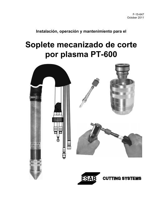
Soplete mecanizado de corte por plasma PT-600
Soplete mecanizado de corte por plasma PT-600
Soplete mecanizado de corte por plasma PT-600

Create successful ePaper yourself
Turn your PDF publications into a flip-book with our unique Google optimized e-Paper software.
DECLARATION OF CONFORMITYaccording to the Low Voltage Directive 2006/95/ECFÖRSÄKRAN OM ÖVERENSSTÄMMELSEenligt Lågspänningsdirektivet 2006/95/EGType of equipment MaterialslagMechanized Plasma Cutting TorchBrand name or tra<strong>de</strong> mark Fabrikatnamn eller varumärkeESABType <strong>de</strong>signation etc. Typbeteckning etc.<strong>PT</strong>-<strong>600</strong> SeriesManufacturer’s authorised representative established within the EEAName, address, telephone No, telefax No: Tillverkarens namn, adress, telefon, telefax:ESAB AB, Welding EquipmentEsabvägen, SE-695 81 Laxå, Swe<strong>de</strong>nPhone: +46 586 81 000, Fax: +46 584 411 924Manufacturer positioned outsi<strong>de</strong> the EEAName, address, telephone No, telefax No: Tillverkarens namn, adress, telefon, telefax:ESAB Welding & Cutting Products411 South Ebenezer Road, Florence, South Carolina 29501, USAPhone: +1 843 669 4411, Fax: +1 843 664 4258The following harmonised standard in force within the EEA has been used in the <strong>de</strong>sign:Följan<strong>de</strong> harmoniseran<strong>de</strong> standar<strong>de</strong>r har använts i konstruktionen:EN 60974-7, Arc welding equipment – Part 7: TorchesBy signing this document, the un<strong>de</strong>rsigned <strong>de</strong>clares as manufacturer, or the manufacturer’s authorisedrepresentative established within the EEA, that the equipment in question complies with the safety requirementsstated above.Genom att un<strong>de</strong>rteckna <strong>de</strong>tta dokument försäkrar un<strong>de</strong>rtecknad såsom tillverkare, eller tillverkarens representant inomEES, att angiven materiel uppfyller säkerhetskraven angivna ovan.Date / DatumLaxå 2008-11-14Signature / Un<strong>de</strong>rskriftKent EimbrodtClarificationPosition / BefattningGlobal DirectorEquipment and Automation
<strong>Soplete</strong> <strong>de</strong> <strong>corte</strong> <strong>por</strong> <strong>plasma</strong> <strong>PT</strong>-<strong>600</strong>Tabla <strong>de</strong> ContenidoPáginaSección 1 Seguridad1.1 Introducción......................................................................................... 11.2 Indicaciones <strong>de</strong> seguridad y símbolos................................................... 21.3 Información general acerca <strong>de</strong> la seguridad........................................... 3-41.4 Precauciones en la instalación .............................................................. 41.5 Conexión eléctrica a tierra..................................................................... 51.6 Funcionamiento <strong>de</strong> una máquina <strong>de</strong> <strong>corte</strong> <strong>por</strong> <strong>plasma</strong>........................... 5-91.7 Precauciones en el servicio................................................................... 10-111.8 Referencias <strong>de</strong> seguridad ...................................................................... 111.8.1 EEUU ........................................................................................... 121.8.2 Internacional................................................................................. 13-14Sección 2 Descripción2.1 Generalida<strong>de</strong>s ............................................................................................ 12.2 Alcance ...................................................................................................... 12.3 Opciones disponibles para el paquete........................................................ 12.4 Especificaciones técnicas2.4.1 Del gas para <strong>plasma</strong>............................................................................ 22.4.2 Gas <strong>de</strong> arranque ................................................................................. 22.4.3 Gas secundario ................................................................................... 22.4.4 <strong>Soplete</strong> <strong>PT</strong>-<strong>600</strong>................................................................................... 3Sección 3 Instalación3.1 Generalida<strong>de</strong>s ............................................................................................ 13.2 Conexión <strong>de</strong> la manguera y <strong>de</strong>l haz <strong>de</strong> cables al cuerpo <strong>de</strong>l soplete ......... 13.3 Desarme <strong>de</strong>l haz <strong>de</strong>l soplete <strong>de</strong>l cuerpo <strong>de</strong>l soplete................................... 33.4 Montaje <strong>de</strong>l soplete en la máquina ............................................................ 4i
<strong>Soplete</strong> <strong>de</strong> <strong>corte</strong> <strong>por</strong> <strong>plasma</strong> <strong>PT</strong>-<strong>600</strong>Tabla <strong>de</strong> ContenidoPáginaSección 4 OperaciónPrecauciones <strong>de</strong> seguridad .................................................................. 14.1 Configuración............................................................................................. 24.1.1 Requisitos para cortar en espejo ........................................................ 24.2 Calidad <strong>de</strong>l <strong>corte</strong>........................................................................................ 34.2.1 Introducción....................................................................................... 34.2.2 Angulo <strong>de</strong> <strong>corte</strong> ................................................................................. 34.2.3 Calidad <strong>de</strong> <strong>corte</strong> ................................................................................ 54.2.4 Acabado <strong>de</strong> la superficie ................................................................... 64.2.5 Escoria............................................................................................... 74.2.6 Precisión dimensonal......................................................................... 84.3 Pasajes <strong>de</strong> flujo al soplete.......................................................................... 94.4 Influencia <strong>de</strong> las opciones <strong>de</strong> gas en la calidad <strong>de</strong>l <strong>corte</strong>4.4.1 Introducción....................................................................................... 104.4.2 Aluminio............................................................................................. 114.4.3 Acero al carbono ............................................................................... 124.4.4 Acero inoxidable ............................................................................... 134.5 Datos <strong>de</strong>l proceso4.5.1 Introducción....................................................................................... 154.5.2 Configuraciones <strong>de</strong>l proceso <strong>de</strong> datosAcero al carbono ....................................................................... 16Aluminio..................................................................................... 36Acero inoxidable ....................................................................... 68Sección 5 Mantenimiento5.1 Introducción............................................................................................... 15.2 Cuerpo <strong>de</strong>l soplete .................................................................................... 15.3 Desarme <strong>de</strong>l extremo <strong>de</strong>lantero <strong>de</strong>l soplete............................................... 25.4 Conjunto <strong>de</strong>l extremo <strong>de</strong>lantero................................................................. 5ii
<strong>Soplete</strong> <strong>de</strong> <strong>corte</strong> <strong>por</strong> <strong>plasma</strong> <strong>PT</strong>-<strong>600</strong>Tabla <strong>de</strong> ContenidoPageSección 6 Diagnóstico y solución <strong>de</strong> fallas6.1 Vida reducida <strong>de</strong> los consumibles .......................................................... 16.2 Sin arco piloto ........................................................................................ 26.3 Sin transferencia <strong>de</strong> arco........................................................................ 26.4 Sin flujo previo <strong>de</strong> gas para <strong>plasma</strong>........................................................ 26.5 Sin flujo previo para el gas <strong>de</strong> la atmósfera <strong>de</strong> protección...................... 26.6 El soplete falla en el encendido .............................................................. 36.7 Sin alta frecuencia en el soplete ............................................................. 3Sección 7 Piezas <strong>de</strong> repuesto7.1 General Generalida<strong>de</strong>s ................................................................................ 17.2 Or<strong>de</strong>ring Pedidos ...................................................................................... 17.3 Front End Parts Extremo <strong>de</strong>lantero <strong>de</strong>l soplete <strong>PT</strong>-<strong>600</strong>........................................ 2-37.4 Hoses and Cables Mangueras y cables......................................................... 4-57.5 Complete Assemblies and Tools Conjuntos completos y herramientas.......... 6-77.6 Parts Kits................................................................................................ 8-9Información para el cliente y técnicaContratapa <strong>de</strong>l manualiii
<strong>Soplete</strong> <strong>de</strong> <strong>corte</strong> <strong>por</strong> <strong>plasma</strong> <strong>PT</strong>-<strong>600</strong>Tabla <strong>de</strong> ContenidoPágina <strong>de</strong>jada en blanco intencionalmenteiv
SECCIÓN 11.1 IntroducciónSEGURIDADEl proceso <strong>de</strong> cortar metales mediante un equipo<strong>de</strong> <strong>plasma</strong> pro<strong>por</strong>ciona a la industria unaherramienta valiosa y <strong>de</strong> múltiples usos. Lasmáquinas <strong>de</strong> <strong>corte</strong> ESAB están diseñadas parafacilitar tanto seguridad como eficacia en elfuncionamiento. No obstante, como ocurre concualquier maquinaría, son necesarios una atenciónrazonable a los procedimientos <strong>de</strong> funcionamiento,las precauciones y un uso seguro para lograr unautilidad óptima. Sin im<strong>por</strong>tar que un individuo estéimplicado en el funcionamiento, el mantenimientoo simplemente como mero observador <strong>de</strong>bencumplirse las precauciones y la práctica <strong>de</strong> un usoseguro. El hecho <strong>de</strong> no respetar ciertasprecauciones podría tener como consecuencialesiones personales graves o serios daños en elequipo. Las siguientes precauciones sondirectrices generales aplicables cuando trabaje conmáquinas <strong>de</strong> <strong>corte</strong>. Encontrará precauciones másexplícitas concernientes a la máquina básica y asus accesorios en los manuales <strong>de</strong> instrucciones.Para una información más exhaustiva acerca <strong>de</strong> laseguridad en el campo <strong>de</strong> equipos <strong>de</strong> <strong>corte</strong> ysoldadura, obtenga y lea las publicaciones quefiguran en la lista <strong>de</strong> Referencias recomendadas.<strong>Soplete</strong> <strong>mecanizado</strong> <strong>de</strong> <strong>corte</strong> <strong>por</strong> <strong>plasma</strong> <strong>PT</strong>-<strong>600</strong>1-1
SECCIÓN 11.2 Indicaciones <strong>de</strong> seguridad y símbolos!SEGURIDADLas siguientes palabras y símbolos se utilizan a lolargo <strong>de</strong> este manual. Indican diferentes niveles <strong>de</strong>compromiso con la seguridad.ALERTA o ATENCIÓN. Su seguridad correriesgo o existe un funcionamiento incorrectopotencial <strong>de</strong>l equipo. Se utiliza con otrossímbolos <strong>de</strong> información.!PELIGROSe utiliza para llamar la atención sobrepeligros inmediatos que, <strong>de</strong> no evitarse,causará lesiones personales graves o inclusola muerte.!!ADVERTENCIAPRECAUCIONPRECAUCIONAVISOSe utiliza para llamar la atención sobrepeligros potenciales que podrían ocasionarlesiones personales o incluso la muerte.Se utiliza para llamar la atención sobrepeligros que podrían causar lesionespersonales o daños menores en el equipo.Se utiliza para llamar la atención sobrepeligros que pue<strong>de</strong>n afectar al equipo.Se utiliza para llamar la atención acerca <strong>de</strong>información im<strong>por</strong>tante sobre la instalación,el funcionamiento o el mantenimiento que noestá directamente relacionada con riesgos.1-2<strong>Soplete</strong> <strong>mecanizado</strong> <strong>de</strong> <strong>corte</strong> <strong>por</strong> <strong>plasma</strong> <strong>PT</strong>-<strong>600</strong>
SECCIÓN 1SEGURIDAD1.3 Información general acerca <strong>de</strong> la seguridad!!ADVERTENCIAADVERTENCIALa maquinaría se encien<strong>de</strong> a menudoautomáticamente.Este equipo se mueve en diferentes direcciones ya diferentes velocida<strong>de</strong>s.• El <strong>de</strong>splazamiento <strong>de</strong> maquinaría podríaprovocar aplastamientos.• Sólo personal cualificado <strong>de</strong>berá llevar acabo el funcionamiento y mantenimiento<strong>de</strong> este generador.• Mantenga a todo el personal, material, yequipo que no estén implicados en elproceso <strong>de</strong> producción lejos <strong>de</strong> todo elárea <strong>de</strong>l sistema.• Ro<strong>de</strong>e con vallas toda la celda <strong>de</strong> trabajopara evitar que el personal pase <strong>por</strong> elárea o se encuentre en el espacio <strong>de</strong>trabajo <strong>de</strong>l equipo.• Coloque los símbolos <strong>de</strong> ADVERTENCIAa<strong>de</strong>cuados a la entrada <strong>de</strong> cada celda <strong>de</strong>trabajo.• Siga el procedimiento <strong>de</strong> bloqueo antes<strong>de</strong> proce<strong>de</strong>r a la reparación <strong>de</strong>l equipo.No seguir las instrucciones podríaocasionar lesiones graves o la muerte.Lea y comprenda este manual <strong>de</strong>l operario antes<strong>de</strong> utilizar la máquina.• Lea el procedimiento completo antes <strong>de</strong>lfuncionamiento y mantenimiento <strong>de</strong>lsistema.• Debe prestar especial atención a lasadvertencias <strong>de</strong> peligro que facilitaninformación esencial relacionada con laseguridad <strong>de</strong>l personal y/o posiblesdaños al equipo.• Aquellos que tengan acceso oresponsabilidad sobre el sistema <strong>de</strong>bencumplir estrictamente todas lasprecauciones <strong>de</strong> seguridad relativas alequipo eléctrico y su uso.• Lea la documentación acerca <strong>de</strong> laseguridad disponible en su empresa.<strong>Soplete</strong> <strong>mecanizado</strong> <strong>de</strong> <strong>corte</strong> <strong>por</strong> <strong>plasma</strong> <strong>PT</strong>-<strong>600</strong>1-3
SECCIÓN 1SEGURIDAD!ADVERTENCIANo seguir las instrucciones en lasetiquetas <strong>de</strong> advertencia podría causar lamuerte o lesiones graves.Lea y entienda todas las etiquetas <strong>de</strong>advertencia <strong>de</strong> la máquina.Consulte el manual <strong>de</strong>l operario para obtenermás información acerca <strong>de</strong> la seguridad.1.4 Precauciones en la instalación!ADVERTENCIAEl equipo instalado incorrectamente pue<strong>de</strong>causar lesiones o incluso la muerte.Siga estas indicaciones cuando instale la máquina:• Póngase en contacto con surepresentante <strong>de</strong> ESAB antes <strong>de</strong> proce<strong>de</strong>ra la instalación. El podría aconsejarleseguir ciertas precauciones en relacióncon la instalación <strong>de</strong> tubos conductores yel levantamiento <strong>de</strong> la máquina, etc. paragarantizar la máxima seguridad.• No intente nunca realizar modificacionesen la máquina o agregar complementos alequipo sin consultar previamente con unrepresentante <strong>de</strong> ESAB.• Cumpla los requisitos <strong>de</strong> distancias <strong>de</strong>seguridad para garantizar unfuncionamiento correcto y la seguridad <strong>de</strong>lpersonal.• Debe ser siempre personal cualificado elque realice la instalación, la localización yreparación <strong>de</strong> averías y el mantenimiento<strong>de</strong> este equipo.• Pro<strong>por</strong>cione un <strong>de</strong>sconector <strong>de</strong> pared confusibles <strong>de</strong>l tamaño a<strong>de</strong>cuado cerca <strong>de</strong>lsuministro eléctrico.1-4<strong>Soplete</strong> <strong>mecanizado</strong> <strong>de</strong> <strong>corte</strong> <strong>por</strong> <strong>plasma</strong> <strong>PT</strong>-<strong>600</strong>
SECCIÓN 1SEGURIDAD1.5 Conexión eléctrica a tierraLa conexión eléctrica es imprescindible para unfuncionamiento correcto <strong>de</strong> la máquina así comopara la SEGURIDAD. Consulte esta sección <strong>de</strong>lManual <strong>de</strong> instalación para obtener instrucciones<strong>de</strong>talladas acerca <strong>de</strong> la conexión a tierra.!PELIGROPeligro <strong>de</strong> <strong>de</strong>scarga.Una conexión a tierra incorrecta podríaocasionar lesiones o incluso la muerte.La máquina <strong>de</strong>be estar correctamenteconectada a tierra antes <strong>de</strong> la puesta enfuncionamiento.1.6 Funcionamiento <strong>de</strong> una máquina <strong>de</strong> <strong>corte</strong> <strong>por</strong> <strong>plasma</strong>!!ADVERTENCIAADVERTENCIAPeligro <strong>por</strong> materia <strong>de</strong>spedida yruido.• Las salpicaduras ardiendo podríanquemar y lesionar sus ojos. Lleve gafasprotectoras para proteger sus ojos <strong>de</strong>quemaduras y <strong>de</strong> salpicaduras durante elfuncionamiento.• Las astillas podrían estar ardiendo y caerlejos. Aquellos que se encuentren en losalre<strong>de</strong>dores también <strong>de</strong>berán llevar gafasprotectoras.• El ruido <strong>de</strong>l arco <strong>de</strong> <strong>plasma</strong> podría dañarlos oídos. Lleve la protección a<strong>de</strong>cuadapara sus oídos cuando <strong>corte</strong> sobre agua.Peligro <strong>de</strong> quemaduras.El metal caliente pue<strong>de</strong> producir quemaduras.• No toque la plancha o las piezas <strong>de</strong> metalinmediatamente <strong>de</strong>spués <strong>de</strong> cortar.Espere un tiempo hasta que el metal seenfríe o póngalo bajo el agua.• No toque el soplete <strong>de</strong> <strong>plasma</strong>inmediatamente <strong>de</strong>spués <strong>de</strong> cortar.Espere un tiempo hasta que se enfríe.<strong>Soplete</strong> <strong>mecanizado</strong> <strong>de</strong> <strong>corte</strong> <strong>por</strong> <strong>plasma</strong> <strong>PT</strong>-<strong>600</strong>1-5
SECCIÓN 1SEGURIDAD!ADVERTENCIAVoltaje peligroso. Las <strong>de</strong>scargaseléctricas pue<strong>de</strong>n causar la muerte.• NO toque el soplete <strong>de</strong> <strong>plasma</strong>, la mesa<strong>de</strong> <strong>corte</strong> o las conexiones <strong>de</strong> cables duranteel proceso <strong>de</strong> <strong>corte</strong> <strong>por</strong> <strong>plasma</strong>.• Cierre siempre los suministros eléctricos<strong>de</strong> <strong>plasma</strong> antes <strong>de</strong> tocar o reparar el soplete<strong>de</strong> <strong>plasma</strong>.• Cierre siempre los suministros eléctricos<strong>de</strong> <strong>plasma</strong> antes <strong>de</strong> tocar o reparar cualquiercomponente <strong>de</strong>l sistema.• No toque piezas eléctricas cargadas.• Mantenga todas los paneles y cubiertasen su lugar cuando la máquina estéconectada a una fuente <strong>de</strong> alimentación.• Lleve guantes, calzado y ropa <strong>de</strong>seguridad para aislarse <strong>de</strong> la pieza <strong>de</strong>trabajo y <strong>de</strong> la toma <strong>de</strong> tierra.• Mantenga secos los guantes, el calzado,la ropa, el área <strong>de</strong> trabajo y el equipo.• Reemplace los cables gastados odañados.1-6<strong>Soplete</strong> <strong>mecanizado</strong> <strong>de</strong> <strong>corte</strong> <strong>por</strong> <strong>plasma</strong> <strong>PT</strong>-<strong>600</strong>
SECCIÓN 1SEGURIDAD!ADVERTENCIAPeligro <strong>de</strong> gases.Los va<strong>por</strong>es y gases generados <strong>por</strong> elproceso <strong>de</strong> <strong>corte</strong> <strong>por</strong> <strong>plasma</strong> podrían serpeligrosos para su salud.• NO inhale el va<strong>por</strong> o los gases.• No utilice el soplete <strong>de</strong> <strong>plasma</strong> si elsistema <strong>de</strong> eliminación <strong>de</strong> humos y gases nofunciona correctamente.• Utilice sistemas <strong>de</strong> ventilación adicionalespara eliminar los humos en caso necesario.• Utilice una mascarilla <strong>de</strong> respiración si laventilación no es a<strong>de</strong>cuada.• Pro<strong>por</strong>cione ventilación mecánica positivacuando <strong>corte</strong> acero inoxidable, cobre, cinc,berilio o cadmio. No inhale los va<strong>por</strong>es.• No trabaje cerca <strong>de</strong> operaciones <strong>de</strong><strong>de</strong>sengrasado y pulverización. El calor o losrayos <strong>de</strong>l arco pue<strong>de</strong>n interactuar con elhidrocarburo clorado y formar fosgeno, ungas altamente tóxico, y otros gases irritantes.<strong>Soplete</strong> <strong>mecanizado</strong> <strong>de</strong> <strong>corte</strong> <strong>por</strong> <strong>plasma</strong> <strong>PT</strong>-<strong>600</strong>1-7
SECCIÓN 1SEGURIDAD!ADVERTENCIAPeligro <strong>de</strong> radiación.Los rayos <strong>de</strong>l arco pue<strong>de</strong>n causar daños en losojos y quemaduras en la piel.• Lleve la protección correcta para cuerpo yojos.• Lleve gafas <strong>de</strong> seguridad oscuras conprotección lateral. Consulte el siguientediagrama para el tintado <strong>de</strong> cristalesrecomendado cuando <strong>corte</strong> con <strong>plasma</strong>:Corriente <strong>de</strong>l arco Filtro <strong>de</strong> la lenteHasta 100 Amps Sombra No. 8100-200 Amps Sombra No. 10200-400 Amps Sombra No. 12Más <strong>de</strong> 400 Amps Sombra No. 14• Reemplace las gafas/lentes cuando loscristales tengan marcas o estén rotos• Avise a otras personas en el área paraque no miren directamente al arco a no serque lleven unas gafas <strong>de</strong> seguridada<strong>de</strong>cuadas.• Prepare el área <strong>de</strong> <strong>corte</strong> para reducir elreflejo y la transmisión <strong>de</strong> luz ultravioleta.Utilice una pintura especial en laspare<strong>de</strong>s que absorba la luz UV.Instale pantallas o cortinasprotectoras para reducir la transmisiónultravioleta.1-8<strong>Soplete</strong> <strong>mecanizado</strong> <strong>de</strong> <strong>corte</strong> <strong>por</strong> <strong>plasma</strong> <strong>PT</strong>-<strong>600</strong>
SECCIÓN 1SEGURIDAD!!ADVERTENCIAADVERTENCIAPeligro <strong>de</strong> quemaduras.El calor, las salpicaduras y las chispas pue<strong>de</strong>nprovocar fuego y quemaduras.• No <strong>corte</strong> cerca <strong>de</strong> material inflamable.• No lleve consigo ningún material inflamable(p.ej. encen<strong>de</strong>dor <strong>de</strong> butano).• El arco piloto pue<strong>de</strong> ocasionar quemaduras.Mantenga la boquilla <strong>de</strong>l soplete lejos <strong>de</strong> símismo y <strong>de</strong> otros cuando active el proceso <strong>de</strong><strong>plasma</strong>.• Lleve la protección correcta para cuerpo yojos.• Lleve guantes, calzado <strong>de</strong> seguridad y gorra.• Lleve ropa resistente al fuego que le cubratodas las áreas expuestas.• Lleve pantalones sin dobladillo para evitar laentrada <strong>de</strong> chispas y residuos.• Tenga a su alcance un equipo <strong>de</strong> extinción<strong>de</strong> incendios.Peligro <strong>de</strong> explosión.• Ciertas aleaciones <strong>de</strong> aluminio-litio (Al-Li)fundido pue<strong>de</strong>n causar explosiones cuandoel <strong>corte</strong> <strong>por</strong> <strong>plasma</strong> se realiza SOBRE agua.Dichas aleaciones <strong>de</strong>berán sercortadas en seco sobre una mesaseca.NO <strong>corte</strong> en seco sobre agua.Póngase en contacto con sudistribuidor <strong>de</strong> aluminio para obtenerinformación <strong>de</strong> seguridad adicionalacerca <strong>de</strong> los peligros asociados conestas aleaciones.• No <strong>corte</strong> en ambientes impregnados <strong>de</strong>polvo o va<strong>por</strong>es explosivos.• No lleve ningún material inflamableconsigo (p.ej. un encen<strong>de</strong>dor <strong>de</strong> butano)• No <strong>corte</strong> contenedores que hayancontenido sustancias inflamables.<strong>Soplete</strong> <strong>mecanizado</strong> <strong>de</strong> <strong>corte</strong> <strong>por</strong> <strong>plasma</strong> <strong>PT</strong>-<strong>600</strong>1-9
SECCIÓN 1SEGURIDAD1.7 Precauciones en el servicio!PELIGROVoltaje peligroso. Las <strong>de</strong>scargaseléctricas pue<strong>de</strong>n causar la muerte.• NO toque el soplete <strong>de</strong> <strong>plasma</strong>, la mesa <strong>de</strong><strong>corte</strong> o las conexiones <strong>de</strong> cables durante elproceso <strong>de</strong> <strong>corte</strong> <strong>por</strong> <strong>plasma</strong>.• Cierre siempre los suministros eléctricos<strong>de</strong> <strong>plasma</strong> antes <strong>de</strong> tocar o reparar cualquiercomponente <strong>de</strong>l sistema.• Apague siempre los suministros eléctricos<strong>de</strong> <strong>plasma</strong> antes <strong>de</strong> retirar las cubiertas opaneles para reparar un componente <strong>de</strong>lsistema.• No toque piezas eléctricas cargadas <strong>de</strong>corriente.• Mantenga todas los paneles y cubiertas ensu lugar cuando la máquina esté conectada auna fuente <strong>de</strong> alimentación.• Mantenga secos los guantes, el calzado,la ropa, el área <strong>de</strong> trabajo y el equipo.• Examine los cables conductores a tierra yeléctricos para comprobar si están<strong>de</strong>sgastados o agrietados. Reemplace loscables gastados o dañados. No los utilice siestán <strong>de</strong>fectuosos.• Nunca pase <strong>por</strong> alto los bloqueos <strong>de</strong>seguridad.• Siga los procedimientos <strong>de</strong> bloqueo.PRECAUCIONEstablezca y cumpla el mantenimiento preventivo.Se pue<strong>de</strong> establecer un programa combinado apartir <strong>de</strong> los horarios recomendados.Evite <strong>de</strong>jar equipo <strong>de</strong> pruebas o herramientas<strong>de</strong> mano sobre la máquina. Podríanproducirse daños eléctricos o mecánicosgraves en el equipo o en la máquina.1-10<strong>Soplete</strong> <strong>mecanizado</strong> <strong>de</strong> <strong>corte</strong> <strong>por</strong> <strong>plasma</strong> <strong>PT</strong>-<strong>600</strong>
SECCIÓN 1SEGURIDAD!PRECAUCIONDeberá proce<strong>de</strong>r con sumo cuidado cuandoexamine el sistema <strong>de</strong> circuitos con unosciloscopio o con un voltímetro. Loscircuitos integrados son susceptibles <strong>de</strong>sobretensión. Apague antes <strong>de</strong> utilizarsondas para evitar corto circuitosacci<strong>de</strong>ntales <strong>de</strong> los componentes.Antes <strong>de</strong> que se active el suministro, <strong>de</strong>benestar todos los cuadros <strong>de</strong>l circuito en tomas<strong>de</strong> corrientes, todos los cables conectadoscorrectamente, todos los armarios cerrados ybloqueados, todos los dispositivos <strong>de</strong>protección y cubiertas reemplazados.1.8 Referencias <strong>de</strong> seguridad -- Reglamentos, normativa, directricesSe recomiendan las siguientes publicaciones sobreseguridad en las operaciones <strong>de</strong> <strong>corte</strong> ysoldadura. Estas publicaciones has sidopreparadas para proteger a las personas <strong>de</strong>lesiones o enfermeda<strong>de</strong>s y para proteger lapropiedad <strong>de</strong> posibles daños ocasionados <strong>por</strong> unuso poco seguro. Aunque algunas <strong>de</strong> estaspublicaciones no están relacionadasespecíficamente con este tipo <strong>de</strong> equipo <strong>de</strong> <strong>corte</strong>industrial, se aplican los mismos principios <strong>de</strong>seguridad.<strong>Soplete</strong> <strong>mecanizado</strong> <strong>de</strong> <strong>corte</strong> <strong>por</strong> <strong>plasma</strong> <strong>PT</strong>-<strong>600</strong>1-11
SECCIÓN 1SEGURIDAD1.8.1 EEUU• “Precautions and Safe Practices in Welding and Cutting with Oxygen-FuelGas Equipment,” (Precauciones y uso seguro en la utilización <strong>de</strong>l equipo<strong>de</strong> <strong>corte</strong> y soldadura con gas y oxígeno-combustible) Form 2035. ESABCutting Systems.• “Precautions and Safe Practices for Electric Welding and Cutting,”(Precauciones y prácticas seguras en el <strong>corte</strong> y soldadura eléctricos)Form 52-529. ESAB Cutting Systems.• “Safety in Welding and Cutting” (Seguridad en <strong>corte</strong> y soldadura) - ANSI Z49.1, American Welding Society, 2501 NW 7th Street, Miami, Florida,33125.• “Recommen<strong>de</strong>d Safe Practices for Shiel<strong>de</strong>d Gases for Welding andPlasma Arc Cutting” (Prácticas seguras recomendadas para la protección<strong>de</strong> gases durante la soldadura y el <strong>corte</strong> con arco <strong>de</strong> <strong>plasma</strong>) - AWSC5.10-94, American Welding Society.• “Recommen<strong>de</strong>d Practices for Plasma Arc Welding” (Prácticasrecomendadas para la soldadura con arco <strong>de</strong> <strong>plasma</strong>)- AWS C5.1,American Welding Society.• “Recommen<strong>de</strong>d Practices for Arc Cutting” (Prácticas recomendadas parael <strong>corte</strong> con arco)- AWS C5.2, American Welding Society.• “Safe Practices” (Prácticas seguras) - AWS SP, American WeldingSociety.• “Standard for Fire Protection in Use of Cutting and Welding Procedures”(Normas para la protección en caso <strong>de</strong> fuego en la utilización <strong>de</strong>procedimientos <strong>de</strong> <strong>corte</strong> y soldadura) - NFPA 51B, National FireProtection Association (Asociación Nacional <strong>de</strong> Protección contra elfuego), 60 Batterymarch Street, Boston, Massachusetts, 02110.• “Standard for Installation and Operation of Oxygen - Fuel Gas Systems forWelding and Cutting” (Normas para la instalación y funcionamiento <strong>de</strong>sistemas <strong>de</strong> gas combustible <strong>de</strong> oxígeno en la soldadura y el <strong>corte</strong>)-NFPA 51, National Fire Protection Association.• “Safety Precautions for Oxygen, Nitrogen, Argon, Helium, Carbon Dioxi<strong>de</strong>,Hydrogen, and Acetylene” (Precauciones <strong>de</strong> seguridad para oxígeno,nitrógeno, argón, helio, dióxido <strong>de</strong> carbono, hidrógeno y acetileno) Form3499. ESAB Cutting Systems. Disponible a través <strong>de</strong> su representante<strong>de</strong> ESAB o su distribuidor local.• "Design and Installation of Oxygen Piping Systems" (Diseño e instalación<strong>de</strong> sistemas conductores <strong>de</strong> oxígeno) Form 5110. ESAB CuttingSystems.• “Precautions for Safe Handling of Compressed Gases in Cylin<strong>de</strong>rs”(Precauciones para el manejo seguro <strong>de</strong> gases comprimidos en loscilindros), CGA Standard P-1, Compressed Gas Association.También pue<strong>de</strong> solicitar documentación referente a un uso seguro en lasoperaciones <strong>de</strong> <strong>corte</strong> y soldadura con materiales gaseosos a CompressedGas Association Asociación <strong>de</strong> gases comprimidos), Inc., 500 Fifth Ave., NewYork, NY 10036.1-12<strong>Soplete</strong> <strong>mecanizado</strong> <strong>de</strong> <strong>corte</strong> <strong>por</strong> <strong>plasma</strong> <strong>PT</strong>-<strong>600</strong>
SECCIÓN 1SEGURIDAD1.8.2 InternacionalPrevención <strong>de</strong> acci<strong>de</strong>ntesVBG 1VBG 4VBG 15VBG 48VBG 61VBG 62VBG 87VBG 93VBG 121Estipulaciones generalesEquipo eléctrico y maquinariaSoldadura, <strong>corte</strong> y métodos <strong>de</strong> trabajorelacionadosTrabajos <strong>de</strong> limpieza con chorro <strong>de</strong> perdigonesGasesOxígenoMáquinas <strong>de</strong> chorro <strong>de</strong> líquidoRayos láser, prevención <strong>de</strong> acci<strong>de</strong>ntes y electrotecnologíaRuidoNormativa VDE (Asociación Alemana <strong>de</strong>Ingenieros Eléctricos)VDE 0100VDE0113VDE 0837VDE 0837-50Montaje <strong>de</strong> instalaciones eléctricas con voltajenormal <strong>de</strong> hasta 1000 voltiosEquipo eléctrico <strong>de</strong> maquinas industrialesSeguridad frente a la radiación <strong>de</strong> productosláser; guía <strong>de</strong>l usuario (DIN EN 60825)Especificación para dispositivos <strong>de</strong> protecciónfrente al láserNormas técnicas TRAC para los <strong>de</strong>pósitos <strong>de</strong> acetileno y carburoTRAC-204 Líneas <strong>de</strong> acetilenoTRAC-206TRAC-207Sistemas <strong>de</strong> batería <strong>de</strong> cilindros <strong>de</strong> acetilenoDispositivos <strong>de</strong> seguridadNormas técnicas TRG para gases <strong>de</strong> presiónTRG 100TRG 101TRG 102TRG 104Normativa general para gases <strong>de</strong> presiónGases a presiónMezclas <strong>de</strong> gas técnicasGases a presión; uso alternativo <strong>de</strong> los<strong>de</strong>pósitos <strong>de</strong> gases comprimidos<strong>Soplete</strong> <strong>mecanizado</strong> <strong>de</strong> <strong>corte</strong> <strong>por</strong> <strong>plasma</strong> <strong>PT</strong>-<strong>600</strong>1-13
SECCIÓN 1SEGURIDADNormas DINNormas basadas en DIN EN ISONormativa VDIDIN 2310Parte 1DIN 2310Parte 2DIN 2310Parte 4DIN 2310Parte 5DIN 4844Parte 1DIN EN292/1 y 2DIN EN 559DIN EN 560DIN EN 561DIN EN 626-1DIN EN 848-1DIN EN 1829DIN EN 9013DIN EN12584DIN EN12626DIN EN28206DIN EN31252DIN EN31553DIN EN60204-1DIN EN60825DIN EN 999VDI 2906VDI 2084Corte térmico; terminología y nomenclaturaCorte térmico; <strong>de</strong>terminación <strong>de</strong> la calidad <strong>de</strong> lascaras <strong>de</strong> <strong>corte</strong>Corte térmico; <strong>corte</strong> con arco <strong>de</strong> <strong>plasma</strong>; principios<strong>de</strong>l proceso, calidad, tolerancia dimensionalCorte térmico; <strong>corte</strong> <strong>por</strong> rayo láser <strong>de</strong> materialesmetálicos; principios <strong>de</strong>l procesoEtiquetas <strong>de</strong> seguridad (DIN EN 7287)Seguridad <strong>de</strong> la maquinariaTubos flexibles para soldar, cortar, y procesossimilaresConexiones <strong>de</strong> tubos y tubos flexibles <strong>de</strong>l equipo<strong>de</strong> soldadura, <strong>corte</strong> y procesos similares.Conexión <strong>de</strong> tubos flexibles <strong>de</strong>l equipo <strong>de</strong>soldadura con gasSeguridad <strong>de</strong> las máquinas, reducción <strong>de</strong> riesgospara la saludFresadoras con un solo eje verticalMáquinas <strong>de</strong> chorro <strong>de</strong> agua a alta presiónCorte térmico, <strong>corte</strong> con oxígeno, principios <strong>de</strong>lproceso, tolerancia dimensionalImperfecciones en <strong>corte</strong>s con llama <strong>de</strong>oxi/combustible, con rayo láser y <strong>plasma</strong>Máquinas <strong>de</strong> procesamiento <strong>de</strong> láserPrueba <strong>de</strong> aprobación <strong>de</strong> máquinas <strong>de</strong> <strong>corte</strong> conoxígenoEquipo láserEquipo láser y relacionado con el láserEquipo eléctrico <strong>de</strong> las máquinasSeguridad <strong>de</strong> radiación <strong>de</strong> productos láserDisposición <strong>de</strong> los dispositivos <strong>de</strong> protecciónCalidad <strong>de</strong> las caras <strong>de</strong> <strong>corte</strong> <strong>de</strong> piezas metálicas;<strong>corte</strong> con chorro <strong>de</strong> agua abrasivo y <strong>corte</strong> con arco<strong>de</strong> <strong>plasma</strong>Temperatura <strong>de</strong> la habitación; Sistemas técnicospara talleres <strong>de</strong> soldadura1-14<strong>Soplete</strong> <strong>mecanizado</strong> <strong>de</strong> <strong>corte</strong> <strong>por</strong> <strong>plasma</strong> <strong>PT</strong>-<strong>600</strong>
SECCION 2DESCRIPCION2.1 Generalida<strong>de</strong>s El <strong>Soplete</strong> <strong>mecanizado</strong> <strong>de</strong> <strong>corte</strong> <strong>por</strong> <strong>plasma</strong> <strong>PT</strong>-<strong>600</strong>es un soplete <strong>de</strong> arco <strong>de</strong> <strong>plasma</strong> armado en lafábrica para brindar a los componentes <strong>de</strong>l sopleteconcentricidad y precisión <strong>de</strong> <strong>corte</strong> uniforme. Poresta razón, el cuerpo <strong>de</strong>l soplete no se pue<strong>de</strong>reparar en el terreno. Sólo el extremo frontal <strong>de</strong>lsoplete tiene piezas reemplazables.2.2 Alcance El propósito <strong>de</strong> este manual es proveer al operadortoda la información requerida para instalar y operarel <strong>Soplete</strong> <strong>mecanizado</strong> <strong>de</strong> <strong>corte</strong> <strong>por</strong> <strong>plasma</strong> <strong>PT</strong>-<strong>600</strong>. También se provee material <strong>de</strong> referenciatécnica para asistir en el diagnóstico y solución <strong>de</strong>fallas <strong>de</strong>l paquete <strong>de</strong> <strong>corte</strong>.2.3 Opciones disponibles <strong>de</strong>l paqueteOpciones <strong>de</strong>l paquete <strong>PT</strong>-<strong>600</strong> disponibles a través <strong>de</strong> su proveedor ESAB:Vea los números <strong>de</strong> pieza <strong>de</strong> los componentes <strong>de</strong> reemplazo en la sección 7.<strong>Soplete</strong> para la cabeza con filo biselado “mini” conconductor <strong>de</strong> 12 pies (3,7 m)<strong>Soplete</strong> para la cabeza con filo biselado “mini” conconductor <strong>de</strong> 14 pies (4,3 m)<strong>Soplete</strong> para la cabeza con filo biselado “mini” conconductor <strong>de</strong> 14 pies (4,3 m) ( Karben - Replacement Parts 7.8 )Conjuntos <strong>de</strong> soplete12 pies, (3,7 m) 056099858914 pies (4,3 m) 055800585014 pies (4,3 m) 05580075804,5 pies, (1,3 m) 05580018276 pies, (1,8 m) 05580018287.2 pies, (2,2m) 055800412312 pies, (3,7 m) 055800182915 pies, (4,6 m) 055800183017 pies, (5,2 m) 055800183120 pies, (6,1 m) 055800183225 pies, (7,6 m) 0558001833NOTAS:•••El cable <strong>de</strong> control <strong>de</strong>s<strong>de</strong> la fuente <strong>de</strong> alimentación hasta el control numérico <strong>por</strong> computadora (CNC) <strong>de</strong>lcliente se provee basado en el pedido <strong>de</strong>l cliente.Vea las piezas <strong>de</strong> reemplazo para los componentes <strong>de</strong> los conjuntos.Vea la lista <strong>de</strong> las piezas consumibles <strong>de</strong>l extremo <strong>de</strong> los sopletes en las Planillas <strong>de</strong> Procesos.S oplete <strong>mecanizado</strong> <strong>de</strong> <strong>corte</strong> <strong>por</strong> plas ma P T-<strong>600</strong> 2-1
SECCION 2DESCRIPCION2.4 Especificaciones técnicas <strong>de</strong>l soplete <strong>PT</strong>-<strong>600</strong>2.4.1 Especificaciones técnicas <strong>de</strong>l gas para el <strong>plasma</strong>Tipo O 2, N 2, Aire, H-35PresiónFlujoPureza requerida*Reguladores recomendadospara el cilindro <strong>de</strong> líquido <strong>de</strong>servicioReguladores recomendadospara el cilindro <strong>de</strong> la segundaetapaReguladores recomendadospara la estación <strong>de</strong> servicioreforzado <strong>de</strong> flujo alto o para latubería.Reguladores recomendadospara la estación <strong>de</strong> altacapacidad o para la tubería.Filtro <strong>de</strong> gas requerido100 a 125 psig (6,9 a 8,6 bars ind.)250 pies 3 /min. (118 l/min.) máx. a <strong>600</strong> A(varía con el uso)O 2-99,5%N 2-99,995%H-35 gas especializadoAire limpio, seco y sin aceiteOxígeno: R-76-150-540LC (P/N 19777)Gas inerte: R-76-150-580LC (P/N 19977)Oxígeno: R-77-150-540 (P/N 998337Hidrógeno/metano:R-77-150-350 (P/N 998342)Nitrógeno: R-77-150-580 (P/N 998344)Aire industrial: R-77150-590 (P/N 998348)Oxígeno: R-76-150-024 (P/N 19151)R-6703 (P/N 22236)De 25 micrones con taza <strong>de</strong> protección(P/N 56998133)2.4.2 Especificaciones técnicas <strong>de</strong>l gas <strong>de</strong> arranqueTipo N 2, Aire, H-35Presión100 a 125 psig (6,9 a 8,6 bars ind.)Flujo250 pies 3 /min (118 l/min.) máx. con <strong>600</strong> A (varíacon el uso)Pureza mínima requerida 99,995% limpio, seco sin aceite2.4.3 Especificaciones técnicas <strong>de</strong>l gas secundarioTipoN 2, AirePresión100 a 125 psig (6.9 a 8,6 bars ind.)Flujo485 pies 3 /min (228,9 l/min.) máx. (varía con el uso)Pureza mínima requerida99.995% limpio, seco sin aceite (misma fuente queel gas <strong>de</strong> arranque)Filtro <strong>de</strong> gas requeridoDe 25 micrones con taza <strong>de</strong> protección (P/N56998133)2-2<strong>Soplete</strong> <strong>mecanizado</strong> <strong>de</strong> <strong>corte</strong> <strong>por</strong> <strong>plasma</strong> <strong>PT</strong>-<strong>600</strong>
SECCION 2DESCRIPCION2.4.4 Especificaciones técnicas <strong>de</strong>l soplete <strong>PT</strong>-<strong>600</strong>TipoEnfriado <strong>por</strong> agua, dos gasesCapacidad nominal <strong>600</strong> A con el ciclo <strong>de</strong> trabajo <strong>de</strong>l 100%DimensionesVea las opciones <strong>de</strong>l paquete en estasección (2.3)<strong>Soplete</strong> <strong>mecanizado</strong> <strong>de</strong> <strong>corte</strong> <strong>por</strong> <strong>plasma</strong> <strong>PT</strong>-<strong>600</strong> 2-3
SECCION 2DESCRIPCIONPágina <strong>de</strong>jada intencionalmente en blanco.2-4<strong>Soplete</strong> <strong>mecanizado</strong> <strong>de</strong> <strong>corte</strong> <strong>por</strong> <strong>plasma</strong> <strong>PT</strong>-<strong>600</strong>
SECCION 33.1 Generalida<strong>de</strong>sINSTALACIONEl soplete <strong>PT</strong>-<strong>600</strong> se provee con el extremocompletamente armado con consumibles para 250A.Pue<strong>de</strong> ser necesario armar el cable <strong>de</strong>l arco piloto ylas mangueras.3.2 Conexión <strong>de</strong>l haz <strong>de</strong> mangueras y cables al cuerpo <strong>de</strong>l soplete1. Destornille el manguito <strong>de</strong>l soplete <strong>PT</strong>-<strong>600</strong> y<strong>de</strong>slícelo sobre el haz <strong>de</strong>l soplete hasta queque<strong>de</strong> expuesto el punto <strong>de</strong> conexión <strong>de</strong>l arcopiloto.Conexión <strong>de</strong>larco pilotoexpuestaConexiones<strong>de</strong>l agua <strong>de</strong>enfriamiento ycorriente <strong>de</strong> <strong>plasma</strong>Conexiones<strong>de</strong> gasCuerpo<strong>de</strong>lsopleteHaz <strong>de</strong>l sopleteCable <strong>de</strong>larcopilotoManguito<strong>de</strong>slizado sobre elhaz <strong>de</strong>l sopleteManguitoaislador <strong>de</strong>lsopleteNOTA: Para exponer la conexión <strong>de</strong>l arco piloto,será necesario <strong>de</strong>slizar el manguito exterior <strong>de</strong>l haz<strong>de</strong>l soplete hacia la fuente <strong>de</strong> alimentación.2. Conecte las mangueras <strong>de</strong> ENTRADA <strong>de</strong>l agua<strong>de</strong> enfriamiento (rosca <strong>de</strong> paso izquierdo) y <strong>de</strong>SALIDA <strong>de</strong>l agua <strong>de</strong> enfriamiento (rosca <strong>de</strong>paso <strong>de</strong>recho) al cuerpo <strong>de</strong>l soplete. Senecesita una llave <strong>de</strong> boca <strong>de</strong> 1/2 pulgada.NOTA: Las mangueras <strong>de</strong> enfriamiento (ENTRADAy SALIDA), tienen el mismo número <strong>de</strong> pieza. Elconjunto requiere dos mangueras. Las manguerasestán diseñadas con una tuerca <strong>de</strong> paso <strong>de</strong>rechoen un extremo y una tuerca <strong>de</strong> paso izquierdo en elotro. Para hacer las conexiones a<strong>de</strong>cuadas inviertael extremo <strong>de</strong> una <strong>de</strong> las mangueras eintercámbielo con el otro.NOTA: Los tubos <strong>de</strong>l agua <strong>de</strong> enfriamiento sonmás cortos que los tubos <strong>de</strong> los gases.3. Conecte los herrajes <strong>de</strong> la conexión <strong>de</strong> gases.Para evitar una conexión cruzada, el herraje <strong>de</strong>conexión <strong>de</strong>l gas <strong>de</strong> <strong>corte</strong> tiene un diámetromenor que el <strong>de</strong>l gas <strong>de</strong> la atmósferaprotectora. Se necesitan llaves <strong>de</strong> 7/16 y 1/2pulgada.NOTA: Es posible cruzar una <strong>de</strong> las conexiones <strong>de</strong>agua con una <strong>de</strong> las conexiones <strong>de</strong> gas. Cadamanguera <strong>de</strong> agua lleva en el interior un cableconductor <strong>de</strong> voltaje.4. Inserte el cable expuesto <strong>de</strong>l arco piloto en elconector <strong>de</strong> cobre para alta frecuencia (HF).Apriete los tornillos <strong>de</strong> fijación usando una llavehexagonal interna (es <strong>de</strong>cir una llave Allen) <strong>de</strong>1/16 pulgada.<strong>Soplete</strong> <strong>mecanizado</strong> <strong>de</strong> <strong>corte</strong> <strong>por</strong> <strong>plasma</strong> <strong>PT</strong>-<strong>600</strong> 3-1
SECCION 3INSTALACION<strong>Soplete</strong>5. Deslice el tubo <strong>de</strong> PVC <strong>de</strong> 0,56 pulg. <strong>de</strong>diámetro hacia abajo, sobre el conector <strong>de</strong>cobre <strong>de</strong> HF. Fíjelo con cinta <strong>de</strong> PVC paraelectricidad, arrollándola sobre el cable pilotolas veces necesarias para evitar que el aislador<strong>de</strong> PVC se <strong>de</strong>slice hacia arriba.Manguito <strong>de</strong>lsopleteAislador <strong>de</strong>la conexión<strong>de</strong>l arcopilotoCuerpo <strong>de</strong>lsoplete6. Deslice el manguito <strong>de</strong>l soplete hacia abajosobre la conexión <strong>de</strong>l cable <strong>de</strong>l arco piloto y losherrajes <strong>de</strong> la manguera. Enrosque el manguitosobre el cuerpo <strong>de</strong>l soplete.Manguito<strong>de</strong>l haz <strong>de</strong>lsopleteCinta que fija lamalla <strong>de</strong> blindajeNOTA: Si fue necesario retirar la cinta negra quefijaba la malla <strong>de</strong> blindaje para liberar el manguito<strong>de</strong>l soplete, reemplácela con cinta <strong>de</strong> PVC para usoen electricidad.3-2<strong>Soplete</strong> <strong>mecanizado</strong> <strong>de</strong> <strong>corte</strong> <strong>por</strong> <strong>plasma</strong> <strong>PT</strong>-<strong>600</strong>
SECCION 3INSTALACION7. Deslice hacia abajo el manguito <strong>de</strong> goma negra<strong>de</strong>l haz <strong>de</strong>l soplete hacia el manguito <strong>de</strong>lsoplete. Estire el manguito <strong>de</strong>l haz <strong>de</strong>l sopletesobre el extremo <strong>de</strong>l manguito <strong>de</strong>l soplete hastalograr una superposición <strong>de</strong> 1 a 1 1/2 pulg. (25a 38 mm).Manguito <strong>de</strong>lhaz <strong>de</strong>l soplete8. Fíjelos con la abraza<strong>de</strong>ra <strong>de</strong> acero inoxidable <strong>de</strong>la manguera (1,56 pulg. <strong>de</strong> DI. x 2,5 pulg. <strong>de</strong>DE).!PELIGRO¡El choque eléctrico pue<strong>de</strong> matar!Antes <strong>de</strong> efectuar el servicio técnico alsoplete, <strong>de</strong>sconecte la fuente <strong>de</strong> alimentaciónprincipal.No toque las piezas <strong>de</strong>l extremo frontal <strong>de</strong>lsoplete (boquilla, taza <strong>de</strong> retención <strong>de</strong>lblindaje, etc.) sin haber colocado en OFF lafuente <strong>de</strong> alimentación eléctrica principal.3.3 Desarme <strong>de</strong>l haz <strong>de</strong>l soplete <strong>de</strong>l cuerpo <strong>de</strong>l sopleteInvierta el sentido <strong>de</strong> armado.1. Afloje la abraza<strong>de</strong>ra <strong>de</strong> la manguera quesostiene el manguito <strong>de</strong>l haz.2. Deslice el manguito <strong>de</strong>l haz hacia arriba. Pue<strong>de</strong>ser necesario <strong>de</strong>senrollar la cinta paraelectricidad que fija la malla <strong>de</strong> blindaje siinterfiere con el manguito <strong>de</strong>l soplete al<strong>de</strong>slizarlo hacia arriba en el haz <strong>de</strong>l soplete.3. Desenrosque el manguito <strong>de</strong>l soplete y <strong>de</strong>slícelohacia arriba <strong>de</strong>l haz <strong>de</strong>l soplete para exponer elpunto <strong>de</strong> conexión <strong>de</strong>l arco piloto.4. Retire la cinta para electricidad que fija elaislador <strong>de</strong> la conexión <strong>de</strong>l arco piloto.5. Deslice el aislador <strong>de</strong>l arco piloto hacia arriba enel cable y afloje los tornillos en el conector <strong>de</strong>HF.6. Desconecte las mangueras.<strong>Soplete</strong> <strong>mecanizado</strong> <strong>de</strong> <strong>corte</strong> <strong>por</strong> <strong>plasma</strong> <strong>PT</strong>-<strong>600</strong> 3-3
SECCION 3INSTALACION3.4 Montaje <strong>de</strong>l soplete en la máquina.Refiérase al manual <strong>de</strong> la máquina.!ADVERTENCIAEl fijar el cuerpo <strong>de</strong>l soplete conabraza<strong>de</strong>ras pue<strong>de</strong> hacer fluir corrientespeligrosas a través <strong>de</strong>l chasis <strong>de</strong> lamáquina.• No lo monte sobre el cuerpo <strong>de</strong> aceroinoxidable <strong>de</strong>l soplete.Monte el sopleteaquí, sobre elmanguito aisladoNO lo monte aquíen el cuerpo <strong>de</strong>acero <strong>de</strong>l sopleteCAUTION: CLAMP TORCH ABOVE THIS LA<strong>PT</strong>-<strong>600</strong>PLASMARC TORCHBEL• El cuerpo <strong>de</strong>l soplete está aisladoeléctricamente. Sin embargo la corriente <strong>de</strong>arranque <strong>de</strong> alta frecuencia pue<strong>de</strong> saltar enarco buscando una conexión a tierra.• Colocar las abraza<strong>de</strong>ras cerca <strong>de</strong>l cuerpo <strong>de</strong>lsoplete pue<strong>de</strong> dar como resultado un arcoeléctrico entre el cuerpo y la máquina.• Si se produce este arco eléctrico, el cuerpo <strong>de</strong>lsoplete pue<strong>de</strong> necesitar reemplazos nocubiertos <strong>por</strong> la garantía.• Pue<strong>de</strong>n producirse daños a la máquina.• Fíjelo con abraza<strong>de</strong>ras sólo sobre el manguitoaislado <strong>de</strong>l soplete, a no menos <strong>de</strong> 1,25 pulg.(31,75 mm) <strong>de</strong>s<strong>de</strong> el extremo <strong>de</strong>l manguito queda hacia el soplete.3-4<strong>Soplete</strong> <strong>mecanizado</strong> <strong>de</strong> <strong>corte</strong> <strong>por</strong> <strong>plasma</strong> <strong>PT</strong>-<strong>600</strong>
SECCION 4 OPERACION!PELIGRO¡El choque eléctrico pue<strong>de</strong> matar!• Antes <strong>de</strong> efectuar cualquier ajuste, <strong>de</strong>sconecte lafuente <strong>de</strong> alimentación principal.• Antes <strong>de</strong> efectuar mantenimiento en loscomponentes <strong>de</strong>l sistema, <strong>de</strong>sconecte la fuente <strong>de</strong>alimentación principal.• No toque las piezas <strong>de</strong>l extremo frontal <strong>de</strong>l soplete(boquilla, taza <strong>de</strong> retención <strong>de</strong>l blindaje, etc.) sinhaber colocado en OFF la fuente <strong>de</strong> alimentacióneléctrica principal.!ADVERTENCIARiesgo <strong>de</strong> radiaciones.Los rayos <strong>de</strong>l arco lesionan los ojos y queman la piel• Use protección a<strong>de</strong>cuada en los ojos y el cuerpo.• Use gafas <strong>de</strong> seguridad o antiparras oscuras con protectoreslaterales. Al cortar con <strong>plasma</strong>, refiérase a la tabla que siguepara obtener la graduación <strong>de</strong> las lentes:Corriente <strong>de</strong>l arcoLenteHasta 100 A Graduación Nº 8100 a 200 A Graduación Nº 10200 a 400 A Graduación Nº 12Más <strong>de</strong> 400 A Graduación Nº 14• Reemplace las gafas/antiparras cuando las lentes esténpicadas o rotas.• Advierta a otros en la zona <strong>de</strong> no mirar directamente al arco,salvo si usan gafas <strong>de</strong> seguridad a<strong>de</strong>cuadas.• Prepare la zona <strong>de</strong> <strong>corte</strong> para reducir las reflexiones y latransmisión <strong>de</strong> luz ultravioleta.• Para reducir las reflexiones, pinte las pare<strong>de</strong>s y otrassuperficies con colores oscuros.• Instale pantallas o cortinas protectoras para reducir latransmisión ultravioleta.<strong>Soplete</strong> <strong>mecanizado</strong> <strong>de</strong> <strong>corte</strong> <strong>por</strong> <strong>plasma</strong> <strong>PT</strong>-<strong>600</strong> 4-1
SECCION 4 OPERACION!ADVERTENCIA¡El aceite y la grasa se pue<strong>de</strong>n quemarviolentamente!• No use nunca aceite o grasa en este soplete.• Manipule el soplete con las manos limpias sobresuperficies limpias.• Use lubricante <strong>de</strong> siliconas sólo don<strong>de</strong> así estéindicado.• El aceite y la grasa se encien<strong>de</strong>n con facilidad y sequeman violentamente en presencia <strong>de</strong> oxígeno apresión.4.1 Configuración• Seleccione una condición apropiada <strong>de</strong> losdatos <strong>de</strong> proceso (archivo SDP) e instale laspiezas (boquilla, electrodo, etc) <strong>de</strong>l extremorecomendado. Vea los datos <strong>de</strong>l proceso parai<strong>de</strong>ntificar las piezas y configuraciones.• Coloque el soplete en posición sobre laubicación inicial <strong>de</strong>seada.• Vea las configuraciones apropiadas en elManual <strong>de</strong> la fuente <strong>de</strong> alimentación.• Vea los procedimientos <strong>de</strong> control <strong>de</strong>l gas enManual <strong>de</strong> control <strong>de</strong> flujo.• Vea los procedimientos <strong>de</strong> arranque en losManuales <strong>de</strong> la máquina.4.1.1 Corte en espejoAl cortar en espejo, se necesita una pantalla<strong>de</strong>flectora inversora <strong>de</strong> vórtice y un difusor inversor.Estas piezas inversoras harán “rotar” el gas endirección opuesta, invirtiendo el lado “bueno” <strong>de</strong>l<strong>corte</strong>.Pantalla <strong>de</strong>flectora inversora orificio 4 0558002534Pantalla <strong>de</strong>flectora inversora orificio 8 0558002530Pantalla <strong>de</strong>flectora inversora orificio 32 0558002531Difusor inversor 224964-2<strong>Soplete</strong> <strong>mecanizado</strong> <strong>de</strong> <strong>corte</strong> <strong>por</strong> <strong>plasma</strong> <strong>PT</strong>-<strong>600</strong>
SECCION 4 OPERACION4.2 Calidad <strong>de</strong> <strong>corte</strong>4.2.1 IntroducciónLas causas que afectan la calidad <strong>de</strong>l <strong>corte</strong> estáninterrelacionadas. Al modificar una variable se afectantodas las otras. La <strong>de</strong>terminación <strong>de</strong> una soluciónpue<strong>de</strong> ser difícil. La guía que sigue ofrece solucionesposibles a resultados <strong>de</strong> <strong>corte</strong> in<strong>de</strong>seables. Paracomenzar, seleccione la condición más prominente:4.2.2 Angulo <strong>de</strong> <strong>corte</strong>, negativo o positivo4.2.3 Corte no plano, redon<strong>de</strong>ado o recortado4.2.4 Rugosidad <strong>de</strong> la superficie4.2.5 EscoriaNormalmente los parámetros <strong>de</strong> <strong>corte</strong> recomendadosdarán la calidad <strong>de</strong> <strong>corte</strong> óptima. Ocasionalmente lascondiciones pue<strong>de</strong>n variar y se requerirán ligerosajustes. Si es así:• Al efectuar correcciones haga variaciones conincrementos pequeños.• Ajuste el voltaje <strong>de</strong>l arco en incrementos <strong>de</strong> unvoltio(1 V), aumentando o disminuyendo según seanecesario..AVISOAntes <strong>de</strong> intentar CUALQUIER corrección, verifique lasvariables <strong>de</strong> <strong>corte</strong> con las configuraciones y losnúmeros<strong>de</strong> pieza con los enumerados en los Datos <strong>de</strong> proceso.<strong>Soplete</strong> <strong>mecanizado</strong> <strong>de</strong> <strong>corte</strong> <strong>por</strong> <strong>plasma</strong> <strong>PT</strong>-<strong>600</strong> 4-3
SECCION 4 OPERACION4.2.2 Angulo <strong>de</strong> <strong>corte</strong>Angulo <strong>de</strong> <strong>corte</strong> negativoLa dimensión superior es mayor que la inferior.Pieza• <strong>Soplete</strong> falto <strong>de</strong> alineación• Material doblado o pan<strong>de</strong>adoRe<strong>corte</strong>Pieza• Consumibles gastados o dañados• Aislador bajo (voltaje <strong>de</strong>l arco)• Velocidad <strong>de</strong> <strong>corte</strong> lenta (velocidad <strong>de</strong><strong>de</strong>splazamiento <strong>de</strong> la máquina)Angulo <strong>de</strong> <strong>corte</strong> positivoLa dimensión superior es menor que la inferior.Pieza• <strong>Soplete</strong> falto <strong>de</strong> alineaciónRe<strong>corte</strong>Pieza• Material doblado o pan<strong>de</strong>ado• Consumibles gastados o dañados• Aislador alto (voltaje <strong>de</strong>l arco)• Velocidad <strong>de</strong> <strong>corte</strong> rápida• Corriente alta o baja (Vea en los datos <strong>de</strong>l procesoel nivel <strong>de</strong> corriente recomendado para boquillasespecíficas).• Flujo <strong>de</strong> gas secundario erróneo.4-4<strong>Soplete</strong> <strong>mecanizado</strong> <strong>de</strong> <strong>corte</strong> <strong>por</strong> <strong>plasma</strong> <strong>PT</strong>-<strong>600</strong>
SECCION 4 OPERACION4.2.3 Acabado <strong>de</strong>l <strong>corte</strong>Parte superior e inferior redon<strong>de</strong>adasEsta condición ocurre normalmente cuando el materialtiene 0,25 pulg. <strong>de</strong> espesor (6,4 mm) o menos.• Corriente alta para el espesor dado <strong>de</strong>l material(Vea las configuraciones correctas en los datos <strong>de</strong>proceso).Re<strong>corte</strong>PiezaBor<strong>de</strong> superior recortadoSeparador bajo (voltaje <strong>de</strong>l arco)Re<strong>corte</strong>Pieza<strong>Soplete</strong> <strong>mecanizado</strong> <strong>de</strong> <strong>corte</strong> <strong>por</strong> <strong>plasma</strong> <strong>PT</strong>-<strong>600</strong> 4-5
SECCION 4 OPERACION4.2.4 Acabado <strong>de</strong> la superficieRugosidad inducida <strong>por</strong> el procesoLa cara <strong>de</strong>l <strong>corte</strong> es uniformemente rugosa y pue<strong>de</strong>estar confinada a un eje.Vista superior• Mezcla <strong>de</strong> gas <strong>de</strong> la atmósfera protectora errónea.(Vea los datos <strong>de</strong> proceso)• Consumibles gastados o dañadosCara cortadaRugosidad inducida <strong>por</strong> la máquinaPue<strong>de</strong> ser difícil distinguir entre la rugosidad inducida<strong>por</strong> el proceso y la inducida <strong>por</strong> la máquina.Normalmente está confinada a un eje. La rugosidadno es uniforme.oRugosidadinducida <strong>por</strong> elprocesoRugosidadinducida <strong>por</strong>la máquina• Rieles, ruedas y/o cremalleras y piñón sucios.(Refiérase a la sección mantenimiento en el manual<strong>de</strong>l propietario)• Ajuste <strong>de</strong> las ruedas <strong>de</strong>l carro <strong>de</strong> <strong>de</strong>splazamiento4-6<strong>Soplete</strong> <strong>mecanizado</strong> <strong>de</strong> <strong>corte</strong> <strong>por</strong> <strong>plasma</strong> <strong>PT</strong>-<strong>600</strong>
SECCION 4 OPERACION4.2.5 EscoriaLa escoria es un subproducto <strong>de</strong>l proceso <strong>de</strong> <strong>corte</strong>.Es el material in<strong>de</strong>seable que permanece unido a lapieza. En la mayoría <strong>de</strong> los casos, la escoria se pue<strong>de</strong>reducir o eliminar con una configuración <strong>de</strong> soplete y<strong>de</strong> parámetros <strong>de</strong> <strong>corte</strong> a<strong>de</strong>cuados. Refiérase a losdatos <strong>de</strong> proceso.Líneas <strong>de</strong>retardoCara <strong>de</strong>l<strong>corte</strong>DesplazadoEscoria <strong>de</strong> alta velocidadMaterial soldado o <strong>de</strong>splazado en la superficie inferiora lo largo <strong>de</strong>l canal o ranura. Difícil <strong>de</strong> remover.Pue<strong>de</strong> requerir <strong>de</strong>sbastado con amoladora o cincel.Líneas <strong>de</strong> retardo con forma <strong>de</strong> “S”.• Separador alto (voltaje <strong>de</strong>l arco)• Velocidad <strong>de</strong> <strong>corte</strong> rápidaVista lateralLíneas <strong>de</strong>retardoCara <strong>de</strong><strong>corte</strong>GlóbulosEscoria <strong>de</strong> baja velocidadSe forma como glóbulos en la parte inferior a lo largo<strong>de</strong>l canal o ranura.• Velocidad <strong>de</strong> <strong>corte</strong> lentaVista lateral<strong>Soplete</strong> <strong>mecanizado</strong> <strong>de</strong> <strong>corte</strong> <strong>por</strong> <strong>plasma</strong> <strong>PT</strong>-<strong>600</strong> 4-7
SECCION 4 OPERACIONVista lateralSalpicadurasEscoria superiorAparece como salpicaduras en la parte superior <strong>de</strong>lmaterial. Normalmente se remueve fácilmente.• Velocidad <strong>de</strong> <strong>corte</strong> rápida• Separador alto (voltaje <strong>de</strong>l arco).Cara <strong>de</strong> <strong>corte</strong>Escoria intermitenteAparece en la parte superior o inferior a lo largo <strong>de</strong>lcanal o la ranura.No continua. Pue<strong>de</strong> aparecer como cualquier tipo <strong>de</strong>escoria.• Posiblemente consumibles gastadosOtros factores que afectan la escoria:• Temperatura <strong>de</strong>l material• Incrustaciones o corrosión fuertes <strong>de</strong>s<strong>de</strong> lametalurgia• Aleaciones con alto contenido <strong>de</strong> carbono4.2.6 Precisión dimensionalAVISONormalmente, al usar la velocidad más lenta posible(<strong>de</strong>ntro <strong>de</strong> los niveles aprobados) optimizará laprecisión <strong>de</strong> la pieza. La mayoría <strong>de</strong> los espesores<strong>de</strong> los materiales se superponen para diferentesvoltajes. Seleccione los consumibles para permitirel menor voltaje <strong>de</strong>l arco y la menor velocidad <strong>de</strong><strong>corte</strong>.La velocidad y el voltaje <strong>de</strong>l arco recomendados,brindarán el rendimiento <strong>de</strong> <strong>corte</strong> óptimo.Pue<strong>de</strong>n ser necesarios pequeños ajustes enaumento <strong>de</strong>bido a la calidad <strong>de</strong>l material,temperatura <strong>de</strong>l material y aleación específica. Eloperador <strong>de</strong>be recordar que todas las variables <strong>de</strong><strong>corte</strong> están interrelacionados. Al modificar unaconfiguración se afectan todas las otras y se pue<strong>de</strong><strong>de</strong>teriorar la calidad <strong>de</strong> <strong>corte</strong>. Comience siemprecon las configuraciones recomendadas.Antes <strong>de</strong> intentar CUALQUIER corrección, verifiquelas variables <strong>de</strong> <strong>corte</strong> con las configuracionesrecomendadas <strong>por</strong> la fábrica y los números <strong>de</strong>pieza enumerados en los datos <strong>de</strong>l proceso.4-8<strong>Soplete</strong> <strong>mecanizado</strong> <strong>de</strong> <strong>corte</strong> <strong>por</strong> <strong>plasma</strong> <strong>PT</strong>-<strong>600</strong>
SECCION 4 OPERACION4.3 Pasajes <strong>de</strong> flujo al sopleteFlujo <strong>de</strong> gasFlujo <strong>de</strong>l agua <strong>de</strong> enfriamientoGas <strong>de</strong>l<strong>plasma</strong>Gas <strong>de</strong> laatmósferaprotectoraENTRADA <strong>de</strong>agua <strong>de</strong>enfriamientoSALIDA <strong>de</strong>agua <strong>de</strong>enfriamiento<strong>Soplete</strong> <strong>mecanizado</strong> <strong>de</strong> <strong>corte</strong> <strong>por</strong> <strong>plasma</strong> <strong>PT</strong>-<strong>600</strong> 4-9
SECCION 4 OPERACION4.4 Influencia <strong>de</strong> las opciones <strong>de</strong> gas en la calidad <strong>de</strong> <strong>corte</strong>4.4.1 IntroducciónNo todos los gases son a<strong>de</strong>cuados para todas lassituaciones. Ciertos gases ayudan a cortarmateriales y espesores específicos. Lo que sigueexplica <strong>por</strong>qué se seleccionan ciertos gases y suinfluencia sobre la pieza terminada. Otrasinfluencias, tales como el voltaje <strong>de</strong>l arco y el flujo ypresión <strong>de</strong>l gas se cubren con los datos <strong>de</strong>lproceso.!PELIGRORiesgo <strong>de</strong> explosión <strong>de</strong> hidrógeno.• ¡No <strong>corte</strong> bajo el agua con gas hidrógeno!• Las explosiones <strong>de</strong> hidrógeno pue<strong>de</strong>n causar lesionesgraves o la muerte.• El hidrógeno pue<strong>de</strong> crear bolsillos <strong>de</strong> gas en el agua <strong>de</strong> lamesa <strong>de</strong> agua. Estos bolsillos explotarán al encen<strong>de</strong>rse acausa <strong>de</strong> las chispas o el arco <strong>de</strong> <strong>plasma</strong>.• Antes <strong>de</strong> cortar, esté alerta sobre posibles fuentes <strong>de</strong>hidrógeno en la mesa <strong>de</strong> agua —reacción <strong>de</strong> metalfundido, reacción química lenta y algunos gases <strong>de</strong>l<strong>plasma</strong>.• Los bolsillos <strong>de</strong> gas explosivo se acumulan <strong>de</strong>bajo <strong>de</strong> laplaca <strong>de</strong> <strong>corte</strong> y <strong>de</strong>ntro <strong>de</strong> la mesa <strong>de</strong> agua.• Limpie frecuentemente la escoria (en especial laspartículas finas) <strong>de</strong>l fondo <strong>de</strong> la mesa <strong>de</strong> trabajo. Rellenela mesa <strong>de</strong> agua con agua limpia.• No <strong>de</strong>je la placa sobre la mesa durante la noche.• Si la mesa <strong>de</strong> agua no se usó durante varias horas, hágalavibrar o sacúdala para romper los bolsillos <strong>de</strong> hidrógenoantes <strong>de</strong> ten<strong>de</strong>r la placa sobre el agua.• Si es posible, cambie el nivel <strong>de</strong> agua entre <strong>corte</strong>s pararomper los bolsillos <strong>de</strong> hidrógeno• Mantenga el nivel <strong>de</strong> pH <strong>de</strong>l agua cerca <strong>de</strong> 7 (neutral).• La separación promedio <strong>de</strong> las piezas <strong>de</strong>be ser comomínimo dos veces el ancho <strong>de</strong>l <strong>corte</strong> para asegurar que elmaterial esté siempre <strong>de</strong>bajo <strong>de</strong>l <strong>corte</strong>.• Al cortar <strong>por</strong> arriba <strong>de</strong>l agua, use ventiladores para hacercircular aire entre la placa y la superficie <strong>de</strong>l agua.4-10<strong>Soplete</strong> <strong>mecanizado</strong> <strong>de</strong> <strong>corte</strong> <strong>por</strong> <strong>plasma</strong> <strong>PT</strong>-<strong>600</strong>
SECCION 4 OPERACION4.4.2 El aluminio y los gases <strong>de</strong>l procesoEspesor <strong>de</strong>l material:Calidad <strong>de</strong>l <strong>corte</strong>:Gas iniciador:Plasma:Atm. <strong>de</strong> protección:Discusión:Espesor <strong>de</strong>l material:Calidad <strong>de</strong>l <strong>corte</strong>:Gas iniciador:Plasma:Atm. <strong>de</strong> protección:Discusión:Espesor <strong>de</strong>l material:Calidad <strong>de</strong>l <strong>corte</strong>:Gas iniciador:Plasma:Atm. <strong>de</strong> protección:Discusión:Espesor <strong>de</strong>l material:Calidad <strong>de</strong>l <strong>corte</strong>:Gas iniciador:Plasma:Atm. <strong>de</strong> protección:Discusión:Espesor <strong>de</strong>l material:Calidad <strong>de</strong>l <strong>corte</strong>:Gas iniciador:Plasma:Atm. <strong>de</strong> protección:Discusión:Espesor <strong>de</strong>l material:Calidad <strong>de</strong>l <strong>corte</strong>:Gas iniciador:Plasma:Atm. <strong>de</strong> protección:Discusión:0,188 a 1,000 pulgadas (4,7 a 25,4 mm)BuenaAireAireAireCara <strong>de</strong> <strong>corte</strong> oscura, escoria potencial, buenos ángulos <strong>de</strong> <strong>corte</strong>0,250 a 3,000 pulgadas (6,4 a 76,2 mm)BuenaN 2H-35N 2Cara <strong>de</strong> <strong>corte</strong> plana, virtualmente sin escoria hasta 1,5 pulg. <strong>de</strong> espesor, ángulos <strong>de</strong><strong>corte</strong> ligeramente mayores con el bor<strong>de</strong> superior redon<strong>de</strong>ado0,625 a 1,000 pulgadas (15.9 a 25,4 mm)BuenaN 2H-35AireCara <strong>de</strong> <strong>corte</strong> ligeramente más oscura, virtualmente sin escoria, ángulos <strong>de</strong> <strong>corte</strong>ligeramente mayores con el bor<strong>de</strong> superior redon<strong>de</strong>ado0,625 a 1,500 pulgadas (15,9 a 38,1 mm)BuenaH-35H-35AireCara <strong>de</strong> <strong>corte</strong> ligeramente más oscura, virtualmente sin escoria, ángulos <strong>de</strong> <strong>corte</strong>ligeramente mayores con el bor<strong>de</strong> superior redon<strong>de</strong>ado0,188 a 1,500 pulgadas (4,7 a 38,1 mm)BuenaN 2N 2AireCara <strong>de</strong> <strong>corte</strong> más oscura, se pue<strong>de</strong> formar escoria en el material <strong>de</strong> más <strong>de</strong> 1 pulg.,buenos ángulos <strong>de</strong> <strong>corte</strong>, ligero redon<strong>de</strong>o <strong>de</strong>l bor<strong>de</strong> superior.0,062 a 1,000 pulgadas (1,6 a 25,4 mm)BuenaN 2N 2N 2Cara <strong>de</strong> <strong>corte</strong> más oscura, se pue<strong>de</strong> formar escoria en el material <strong>de</strong> más <strong>de</strong> 0,75 pulg.,buenos ángulos <strong>de</strong> <strong>corte</strong>, ligero redon<strong>de</strong>o <strong>de</strong>l bor<strong>de</strong> superior.<strong>Soplete</strong> <strong>mecanizado</strong> <strong>de</strong> <strong>corte</strong> <strong>por</strong> <strong>plasma</strong> <strong>PT</strong>-<strong>600</strong> 4-11
SECCION 4 OPERACION4.4.3 Acero al carbonoEspesor <strong>de</strong>l material:Calidad <strong>de</strong>l <strong>corte</strong>:Gas iniciador:Plasma:Atm. <strong>de</strong> protección:Discusión:Espesor <strong>de</strong>l material:Calidad <strong>de</strong>l <strong>corte</strong>:Gas iniciador:Plasma:Atm. <strong>de</strong> protección:Discusión:0,125 a 1,500 pulgadas (3,2 a 38,1 mm)ExcelenteN 2O 2AireCara <strong>de</strong> <strong>corte</strong> lisa brillante, virtualmente sin escoria, buenos ángulos <strong>de</strong> <strong>corte</strong>, bor<strong>de</strong>superior agudo0,062 a 0,250 pulgadas (1,6 a 6,4 mm)BuenaAireAireAireCara <strong>de</strong> <strong>corte</strong> lisa gris, virtualmente sin escoria, ángulos <strong>de</strong> <strong>corte</strong> más gran<strong>de</strong>s <strong>de</strong>bido alespesor <strong>de</strong> la placa, velocidad <strong>de</strong> <strong>corte</strong> y amperaje <strong>de</strong> <strong>corte</strong>.4-12<strong>Soplete</strong> <strong>mecanizado</strong> <strong>de</strong> <strong>corte</strong> <strong>por</strong> <strong>plasma</strong> <strong>PT</strong>-<strong>600</strong>
SECCION 4 OPERACION4.4.4 Acero inoxidableEspesor <strong>de</strong>l material:Calidad <strong>de</strong>l <strong>corte</strong>:Gas iniciador:Plasma:Atm. <strong>de</strong> protección:Discusión:Espesor <strong>de</strong>l material:Calidad <strong>de</strong>l <strong>corte</strong>:Gas iniciador:Plasma:Atm. <strong>de</strong> protección:Discusión:Espesor <strong>de</strong>l material:Calidad <strong>de</strong>l <strong>corte</strong>:Gas iniciador:Plasma:Atm. <strong>de</strong> protección:Discusión:0,062 a 0,750 pulgadas (1,6 a 19,1 mm)BuenaN 2N 2N 2Cara <strong>de</strong> <strong>corte</strong> oscura, virtualmente sin escoria, buenos ángulos <strong>de</strong> <strong>corte</strong>, biselados en elancho <strong>de</strong>bido al espesor, velocidad y amperaje.0,062 a 1,000 pulgadas (1,6 a 25,4 mm)BuenaAireAireAireCara <strong>de</strong> <strong>corte</strong> oscura, virtualmente sin escoria, buenos ángulos <strong>de</strong> <strong>corte</strong>, biselados en elancho <strong>de</strong>bido al espesor, velocidad y amperaje.0,250 a 3,000 pulgadas (6,4 a 76,2 mm)BuenaN 2N 2AireCara <strong>de</strong> <strong>corte</strong> oscura, virtualmente sin escoria, buenos ángulos <strong>de</strong> <strong>corte</strong>, ligeroredon<strong>de</strong>o <strong>de</strong>l bor<strong>de</strong> superiorEspesor <strong>de</strong>l material:Calidad <strong>de</strong>l <strong>corte</strong>:Gas iniciador:Plasma:Atm. <strong>de</strong> protección:0,500 a 3,000 pulgadas (12,7 a 76,2 mm)BuenaN 2H-35N 2Discusión: Cara <strong>de</strong> <strong>corte</strong> brillante color dorado, virtualmente sin escoria hasta material <strong>de</strong> 1,5pulgada, los espesores mayores pue<strong>de</strong>n tener escoria, Angulo <strong>de</strong> <strong>corte</strong> ligeramentemayor <strong>de</strong>bido al gas <strong>de</strong>l <strong>plasma</strong> H-35.<strong>Soplete</strong> <strong>mecanizado</strong> <strong>de</strong> <strong>corte</strong> <strong>por</strong> <strong>plasma</strong> <strong>PT</strong>-<strong>600</strong> 4-13
SECCION 4 OPERACIONPágina <strong>de</strong>jada en blanco intencionalmente4-14<strong>Soplete</strong> <strong>mecanizado</strong> <strong>de</strong> <strong>corte</strong> <strong>por</strong> <strong>plasma</strong> <strong>PT</strong>-<strong>600</strong>
SECCION 4OPERACION4.5 Datos <strong>de</strong>l proceso4.5.1 Introducción La información brindada a continuación es el resultado <strong>de</strong>muchas horas <strong>de</strong> pruebas, y representa una guía general<strong>de</strong> los preparativos y <strong>de</strong>l proceso <strong>de</strong> <strong>corte</strong> con el <strong>Soplete</strong>Mecánico para Corte <strong>de</strong> Arco Eléctrico <strong>por</strong> Plasma <strong>PT</strong>-<strong>600</strong>. El controlador <strong>de</strong>l equipo dirige el flujo <strong>de</strong> gasutilizando el SmartFlow II, un sistema con control <strong>de</strong>válvula pro<strong>por</strong>cional.En la mayoría <strong>de</strong> los casos, estos preparativos le ayudarána realizar un <strong>corte</strong> <strong>de</strong> calidad. Estos datos incluyen losparámetros para: cortar aluminio, carbón y acero inoxidable el voltaje <strong>de</strong>l arco (<strong>de</strong> montaje vertical) velocidad <strong>de</strong> <strong>corte</strong> corriente eléctrica (amperios) velocida<strong>de</strong>s <strong>de</strong>l flujo <strong>de</strong> gas para las combinaciones<strong>de</strong> gas <strong>plasma</strong> / <strong>de</strong> arco protegidoEstos mismos datos se encuentran en los archivos SDP.(Vea su máquina y los manuales <strong>de</strong> programación SDPpara obtener más información acerca <strong>de</strong> estos archivos.)También se brinda información acerca <strong>de</strong> los códigos <strong>de</strong>las piezas consumibles para todas las condiciones <strong>de</strong>corrientes posibles.ATENCIÓNLos parámetros <strong>de</strong> velocidad, voltaje, <strong>corte</strong>y corriente se pue<strong>de</strong>n usar en todas lasaplicaciones <strong>de</strong>l soplete <strong>PT</strong>-<strong>600</strong>.Los datos <strong>de</strong>l proceso surgieron <strong>de</strong>l uso <strong>de</strong>l Smart Flow II,un sistema <strong>de</strong> control programable <strong>de</strong>l flujo <strong>de</strong> gas. Estamisma información se utiliza al crear los archivos <strong>de</strong> control(SDP) para el proceso Vision CNC. Cuando se utiliza elSmart Flow II, las velocida<strong>de</strong>s <strong>de</strong>l flujo <strong>de</strong> gas sólo sebrindan como referencia. La velocidad, el voltaje <strong>de</strong>arco, el <strong>corte</strong> y la corriente (amperios) también seaplican a los <strong>corte</strong>s realizados con sistemas <strong>de</strong>regulación manual <strong>de</strong>l gas.ATENCIÓNLas velocida<strong>de</strong>s <strong>de</strong>l <strong>corte</strong> bajo el agua<strong>de</strong>ben reducirse un 10 %.Como regla general, las velocida<strong>de</strong>s <strong>de</strong> <strong>corte</strong> sobreagua pue<strong>de</strong>n aplicarse al <strong>corte</strong> bajo agua, siempreque las mismas se reduzcan en un 10%. Existen dosejemplos <strong>de</strong> <strong>corte</strong> bajo agua incluidos más a<strong>de</strong>lantecomo referencia (p4-33, p4-93).<strong>Soplete</strong> <strong>mecanizado</strong> <strong>de</strong> <strong>corte</strong> <strong>por</strong> <strong>plasma</strong> <strong>PT</strong>-<strong>600</strong> 4-15
SECCION 4OPERACION<strong>PT</strong>-<strong>600</strong><strong>Soplete</strong> <strong>de</strong> Corte <strong>por</strong> ArcoMaterial:Amperios: 50Gas inicial:Gas <strong>de</strong> <strong>corte</strong>:Acero al CarbonoAire* @ 100 LPPC / 6.9 BarsAire* @ 100 LPPC / 6.9 Bars<strong>de</strong> Plasma Gas <strong>de</strong> protección: Aire* @ 60 LPPC / 4.1 Bars*No use Aire común. Utilice Aire envasado/comprimido.Mango <strong>de</strong>l soplete P/N 0558001626Cuerpo <strong>de</strong>l soplete P/N 0558001825 (Ref.)2 EA. Aros tóricos P/N 996528 (Ref.)Placa <strong>de</strong> <strong>de</strong>sviación <strong>de</strong>l gas P/N0558002533 “4 Orificios”Aro tórico provisto con el <strong>por</strong>taelectrodosP/N 86W99 (Ref.)Portaelectrodo con aro tóricoP/N 0558001621Aro tórico provisto con el electrodo P/N86W99 (Ref.)Electrodo P/N 0558001624 “250A”Aro tórico provisto con la boquillaP/N 181W89 (Ref.)Boquilla P/N 0558001881 “50A”Aro tórico provisto con la boquillaP/N 181W89 (Ref.)Cono <strong>de</strong> contención <strong>de</strong> la boquillaP/N 37082Difusor <strong>de</strong> gasP/N 21796 “50A”Protección P/N 21795 “50A”Protección <strong>de</strong> tope P/N 370814-16<strong>Soplete</strong> <strong>mecanizado</strong> <strong>de</strong> <strong>corte</strong> <strong>por</strong> <strong>plasma</strong> <strong>PT</strong>-<strong>600</strong>
SECCION 4<strong>PT</strong>-<strong>600</strong>: Datos <strong>de</strong>l Proceso50 AmperiosAcero al CarbonoOPERACIONSalvo en los casos que así se indique,los datos son para el <strong>corte</strong> sobre agua.Cuando <strong>corte</strong> bajo el agua, reduzca lavelocidad alre<strong>de</strong>dor <strong>de</strong> un 10%.Gas inicialGas <strong>de</strong><strong>corte</strong>ProtecciónGasEspesor <strong>de</strong>l material Aire Aire AireCronómetrosPULGADAS 0.063MM 1,6Aumento en la perforación (seg.) 0Retardo en la perforación (seg.) 0Parámetros iniciales Libras <strong>por</strong> pulgada cuadrada (LPPC - Presión)Gas <strong>plasma</strong> inicialGas <strong>plasma</strong> <strong>de</strong> <strong>corte</strong>Gas pantalla inicialGas pantalla <strong>de</strong> <strong>corte</strong>Lecturas <strong>de</strong> la alturaAltura inicialLPPC 40BAR 2,76LPPC 50BAR 3,45LPPC 10BAR 0,69LPPC 10BAR 0,69PULG.. .375MM 9,5Voltaje <strong>de</strong>l arco (so<strong>por</strong>te) 113Velocidad <strong>de</strong> recorridoAncho <strong>de</strong> <strong>corte</strong>PULGADAS / MINUTO 220MILÍMETROS / MINUTO 5588Notas:Arco piloto colocado al bajoPulgadas .05Milímetros 1,3<strong>Soplete</strong> <strong>mecanizado</strong> <strong>de</strong> <strong>corte</strong> <strong>por</strong> <strong>plasma</strong> <strong>PT</strong>-<strong>600</strong> 4-17
SECCION 4OPERACION<strong>PT</strong>-<strong>600</strong>Material: Acero al CarbonoAmperios: 65Gas inicial: Aire* @ 100 LPPC / 6,9 Bar<strong>Soplete</strong> <strong>de</strong> Corte <strong>por</strong> Arco Gas <strong>de</strong> <strong>corte</strong>: Aire* @ 100 LPPC / 6,9 Bar<strong>de</strong> Plasma Protección Gas: Aire* @ 60 LPPC / 4,1 Bar*No use Aire común. Utilice Aire envasado/comprimido.Mango <strong>de</strong>l soplete P/N 0558001626Cuerpo <strong>de</strong>l soplete P/N 0558001825 (Ref.)2 EA. Aros tóricos P/N 996528 (Ref.)Placa <strong>de</strong> <strong>de</strong>sviación <strong>de</strong>l gas P/N0558002533 “4 Orificios ”Aro tórico provisto con el <strong>por</strong>taelectrodosP/N 86W99 (Ref.)Portaelectrodo con aro tóricoP/N 0558001621Aro tórico provisto con el electrodo P/N86W99 (Ref.)Electrodo P/N 0558001624 “250A”Aro tórico provisto con la boquillaP/N 181W89 (Ref.)Boquilla P/N 0558001881 “50A”Aro tórico provisto con la boquillaP/N 181W89 (Ref.)Cono <strong>de</strong> contención <strong>de</strong> la boquillaP/N 37082Difusor <strong>de</strong> gasP/N 21796Protección P/N 21796 “50A”Protección <strong>de</strong> tope P/N 370814-18<strong>Soplete</strong> <strong>mecanizado</strong> <strong>de</strong> <strong>corte</strong> <strong>por</strong> <strong>plasma</strong> <strong>PT</strong>-<strong>600</strong>
SECCION 4<strong>PT</strong>-<strong>600</strong>: Datos <strong>de</strong>l Proceso65 AmperiosAcero al CarbonoOPERACIONSalvo en los casos que así se indique,los datos son para el <strong>corte</strong> sobre agua.Cuando <strong>corte</strong> bajo el agua, reduzca lavelocidad alre<strong>de</strong>dor <strong>de</strong> un 10%.Gas inicialGas <strong>de</strong><strong>corte</strong>ProtecciónGasEspesor <strong>de</strong>l material Aire Aire AireCronómetrosPULGADAS 0.125 0.188 0.250MM 3,2 4,7 6,4Aumento en la perforación (seg.) 0 0 0.1Retardo en la perforación (seg.) 0 0 0.4Parámetros iniciales Libras <strong>por</strong> pulgada cuadrada (LPPC - Presión)Gas <strong>plasma</strong> inicialGas <strong>plasma</strong> <strong>de</strong> <strong>corte</strong>Gas pantalla inicialGas pantalla <strong>de</strong> <strong>corte</strong>Lecturas <strong>de</strong> la alturaAltura inicialLPPC 40 40 40BAR 2,76 2,76 2,76LPPC 50 50 50BAR 3,45 3,45 3,45LPPC 10 10 10BAR 0,69 0,69 0,69LPPC 10 10 10BAR 0,69 0,69 0,69PULG.. .375 .375 .375MM 9,5 9,5 9,5Voltaje <strong>de</strong>l arco (so<strong>por</strong>te) 115 118 130Velocidad <strong>de</strong> recorridoAncho <strong>de</strong> <strong>corte</strong>PULGADAS / MINUTO 150 100 75MILÍMETROS / MINUTO 3810 2540 1905Pulgadas .065 .075 .085Milímetros 1,7 1,9 2,2Notas:Arco piloto colocado al bajo<strong>Soplete</strong> <strong>mecanizado</strong> <strong>de</strong> <strong>corte</strong> <strong>por</strong> <strong>plasma</strong> <strong>PT</strong>-<strong>600</strong> 4-19
SECCION 4OPERACION<strong>PT</strong>-<strong>600</strong>Material: Acero al CarbonoAmperios: 100Gas inicial: Nitrógeno (N 2) @100 LPPC / 6,9 Bar<strong>Soplete</strong> <strong>de</strong> Corte <strong>por</strong> Arco Gas <strong>de</strong> <strong>corte</strong>: Oxígeno (O 2)@ 100 LPPC / 6,9 Bar<strong>de</strong> Plasma Protección Gas: Aire * @ 60 LPPC / 4,1 Bar*No use Aire común. Utilice Aire envasado/comprimido.Mango <strong>de</strong>l soplete P/N 0558001626Cuerpo <strong>de</strong>l soplete P/N 0558001825 (Ref.)2 EA. Aros tóricos P/N 996528 (Ref.)Placa <strong>de</strong> <strong>de</strong>sviación <strong>de</strong>l gas P/N0558002533 “4 Orificios ”(0558002534 “Corriente inversa”)Aro tórico provisto con el <strong>por</strong>taelectrodosP/N 86W99 (Ref.)Portaelectrodo con aro tóricoP/N 0558001621O-ring Supplied with ElectrodoP/N 86W99 (Ref.)Electrodo P/N 0558001624 “250A”Aro tórico provisto con la boquillaP/N 181W89 (Ref.)Boquilla P/N 0558001882 “100A”Aro tórico provisto con la boquillaP/N 181W89 (Ref.)Cono <strong>de</strong> contención <strong>de</strong> la boquillaP/N 37082Difusor <strong>de</strong> gasP/N 21944 (22496 “Corriente inversa”)Protección P/N 21802 “100A to 250A”Protección <strong>de</strong> tope P/N 370814-20<strong>Soplete</strong> <strong>mecanizado</strong> <strong>de</strong> <strong>corte</strong> <strong>por</strong> <strong>plasma</strong> <strong>PT</strong>-<strong>600</strong>
SECCION 4<strong>PT</strong>-<strong>600</strong>: Datos <strong>de</strong>l Proceso100 AmperiosAcero al CarbonoOPERACIONSalvo en los casos que así se indique,los datos son para el <strong>corte</strong> sobre agua.Cuando <strong>corte</strong> bajo el agua, reduzca lavelocidad alre<strong>de</strong>dor <strong>de</strong> un 10%.Gas inicialGas <strong>de</strong><strong>corte</strong>ProtecciónGasEspesor <strong>de</strong>l material N 2O 2AireCronómetrosPULGADAS 0.125 0.188 0.250 0.313 0.375 0.500 0.625 0.750MM 3,2 4,7 6,4 7,9 9,5 12,7 15,9 19,1Aumento en la perforación (seg.) 0 0 0 0 0.2 0.4 0.5 0.3Retardo en la perforación (seg.) 0 0 0 0 0.2 0.5 0.6 0.7Parámetros iniciales Libras <strong>por</strong> pulgada cuadrada (LPPC - Presión)Gas <strong>plasma</strong> inicialGas <strong>plasma</strong> <strong>de</strong> <strong>corte</strong>Gas pantalla inicialGas pantalla <strong>de</strong> <strong>corte</strong>Lecturas <strong>de</strong> la alturaAltura inicialLPPC 25 25 25 25 25 25 25 25BAR 1,7 1,7 1,7 1,7 1,7 1,7 1,7 1,7LPPC 46 46 44 46 46 46 48 46BAR 3,2 3,2 3,0 3,2 3,2 3,2 3,3 3,2LPPC 20 20 20 20 20 20 20 18BAR 1,4 1,4 1,4 1,4 1,4 1,4 1,4 1,2LPPC 10 18 18 10 16 10 12 10BAR 0,7 1,2 1,2 0,7 1,1 0,7 0,8 0,7PULG.. .375 .375 .375 .375 .375 .500 .500 .500MM 9,5 9,5 9,5 9,5 9,5 12,7 12,7 12,7Voltaje <strong>de</strong>l arco (so<strong>por</strong>te) 123 135 133 134 149 141 159 162Velocidad <strong>de</strong> recorridoAncho <strong>de</strong> <strong>corte</strong>PULGADAS / MINUTO 190 150 120 100 80 60 38 20MILÍMETROS / MINUTO 4826 3810 3048 2540 2032 1524 965 508Pulgadas .08 .075 .100 .085 .012 .100 .14 .145Milímetros 2,0 1,9 2,5 2,2 3,0 2,5 3,6 3,7Notas:Arco piloto colocado al bajo<strong>Soplete</strong> <strong>mecanizado</strong> <strong>de</strong> <strong>corte</strong> <strong>por</strong> <strong>plasma</strong> <strong>PT</strong>-<strong>600</strong> 4-21
SECCION 4OPERACION<strong>PT</strong>-<strong>600</strong><strong>Soplete</strong> <strong>de</strong> Corte <strong>por</strong> ArcoAcero al CarbonoMaterial:Amperios: 150Gas inicial: Nitrógeno (N 2) @ 100 LPPC / 6,9 BarGas <strong>de</strong> <strong>corte</strong>: Oxígeno (O 2) @ 100 LPPC / 6,9 Bar<strong>de</strong> Plasma Protección Gas: Aire * @ 60 LPPC / 4,1 Bar*No use Aire común. Utilice Aire envasado/comprimido.Mango <strong>de</strong>l soplete P/N 0558001626Cuerpo <strong>de</strong>l soplete P/N 0558001825 (Ref.)2 EA. Aros tóricos P/N 996528 (Ref.)Placa <strong>de</strong> <strong>de</strong>sviación <strong>de</strong>l gas P/N0558002533 “4 Orificios ”(0558002534 “Corriente inversa”)Aro tórico provisto con el <strong>por</strong>taelectrodosP/N 86W99 (Ref.)Portaelectrodo con aro tóricoP/N 0558001621Aro tórico provisto con el electrodo P/N86W99 (Ref.)Electrodo P/N 0558001624 “250A”Aro tórico provisto con la boquillaP/N 181W89 (Ref.)Boquilla P/N 0558001883 “150A”Aro tórico provisto con la boquillaP/N 181W89 (Ref.)Cono <strong>de</strong> contención <strong>de</strong> la boquillaP/N 37082Difusor <strong>de</strong> gasP/N 21944 (22496 “Corriente inversa”)Protección P/N 21802 “100A to 250A”Protección <strong>de</strong> tope P/N 370814-22<strong>Soplete</strong> <strong>mecanizado</strong> <strong>de</strong> <strong>corte</strong> <strong>por</strong> <strong>plasma</strong> <strong>PT</strong>-<strong>600</strong>
SECCION 4<strong>PT</strong>-<strong>600</strong>: Datos <strong>de</strong>l Proceso150 AmperiosAcero al CarbonoOPERACIONSalvo en los casos que así se indique,los datos son para el <strong>corte</strong> sobre agua.Cuando <strong>corte</strong> bajo el agua, reduzca lavelocidad alre<strong>de</strong>dor <strong>de</strong> un 10%.Gas inicialGas <strong>de</strong><strong>corte</strong>ProtecciónGasEspesor <strong>de</strong>l material N 2O 2AireCronómetrosPULGADAS 0.188 0.250 0.313 0.375 0.500 0.625 0.750 1.000MM 4,7 6,4 7,9 9,5 12,7 15,9 19,1 25,4Aumento en la perforación (seg.) 0 0 0 0 0.2 0.2 0.2 0.3Retardo en la perforación (seg.) 0 0 0 0 0.4 0.5 0.8 1.0Parámetros iniciales Libras <strong>por</strong> pulgada cuadrada (LPPC - Presión)Gas <strong>plasma</strong> inicialGas <strong>plasma</strong> <strong>de</strong> <strong>corte</strong>Gas pantalla inicialGas pantalla <strong>de</strong> <strong>corte</strong>Lecturas <strong>de</strong> la alturaAltura inicialLPPC 20 20 20 20 20 20 20 20BAR 1,4 1,4 1,4 1,4 1,4 1,4 1,4 1,4LPPC 37 37 37 37 37 44 37 37BAR 2,6 2,6 2,6 2,6 2,6 3,0 2,6 2,6LPPC 20 20 20 20 20 21 18 18BAR 1,4 1,4 1,4 1,4 1,4 1,5 1,2 1,2LPPC 18 18 18 18 16 18 10 16BAR 1,2 1,2 1,2 1,2 1,1 1,2 0,7 1,1PULG.. .375 .375 .375 .375 .500 .500 .500 .500MM 9,5 9,5 9,5 9,5 12,7 12,7 12,7 12,7Voltaje <strong>de</strong>l arco (so<strong>por</strong>te) 127 126 131 134 140 151 157 156Velocidad <strong>de</strong> recorridoAncho <strong>de</strong> <strong>corte</strong>PULGADAS / MINUTO 160 150 120 90 75 55 45 25MILÍMETROS / MINUTO 4064 3810 3048 2286 1905 1397 1143 635Pulgadas .085 .095 .095 .120 .105 .125 .150 .165Milímetros 2,2 2,4 2,4 3,0 2,7 3,2 3,8 4,2Notas:Arco piloto colocado al alto<strong>Soplete</strong> <strong>mecanizado</strong> <strong>de</strong> <strong>corte</strong> <strong>por</strong> <strong>plasma</strong> <strong>PT</strong>-<strong>600</strong> 4-23
SECCION 4OPERACION<strong>PT</strong>-<strong>600</strong><strong>Soplete</strong> <strong>de</strong> Corte <strong>por</strong> ArcoAcero al CarbonoMaterial:Amperios: 200Gas inicial: Nitrógeno (N 2) @ 100 LPPC / 6,9 BarGas <strong>de</strong> <strong>corte</strong>: Oxígeno (O 2) @ 100 LPPC / 6,9 Bar<strong>de</strong> Plasma Protección Gas: Aire * @ 60 LPPC / 4,1 Bar*No use Aire común. Utilice Aire envasado/comprimido.Mango <strong>de</strong>l soplete P/N 0558001626Cuerpo <strong>de</strong>l soplete P/N 0558001825 (Ref.)2 EA. Aros tóricos P/N 996528 (Ref.)Placa <strong>de</strong> <strong>de</strong>sviación <strong>de</strong>l gas P/N0558002533 “4 Orificios ”(0558002534 “Corriente inversa”)Aro tórico provisto con el <strong>por</strong>taelectrodosP/N 86W99 (Ref.)Portaelectrodo con aro tóricoP/N 0558001621Aro tórico provisto con el electrodo P/N86W99 (Ref.)Electrodo P/N 0558001624 “250A”Aro tórico provisto con la boquillaP/N 181W89 (Ref.)Boquilla P/N 0558001884 “200A”Aro tórico provisto con la boquillaP/N 181W89 (Ref.)Cono <strong>de</strong> contención <strong>de</strong> la boquillaP/N 37082Difusor <strong>de</strong> gasP/N 21944 (22496 “Corriente inversa”)Protección P/N 21802 “100A to 250A”Protección <strong>de</strong> tope P/N 370814-24<strong>Soplete</strong> <strong>mecanizado</strong> <strong>de</strong> <strong>corte</strong> <strong>por</strong> <strong>plasma</strong> <strong>PT</strong>-<strong>600</strong>
SECCION 4<strong>PT</strong>-<strong>600</strong>: Datos <strong>de</strong>l Proceso200 AmperiosAcero al CarbonoOPERACIONSalvo en los casos que así se indique,los datos son para el <strong>corte</strong> sobre agua.Cuando <strong>corte</strong> bajo el agua, reduzca lavelocidad alre<strong>de</strong>dor <strong>de</strong> un 10%.Gas inicialGas <strong>de</strong><strong>corte</strong>ProtecciónGasEspesor <strong>de</strong>l material N 2O 2AireCronómetrosPULGADAS 0.250 0.313 0.375 0.500 0.625 0.750 1.000 1.250MM 6,4 7,9 9,5 12,7 15,9 19,1 25,4 31,8Aumento en la perforación (seg.) 0 0 0 0.1 0.2 0.3 0.3 0.6Retardo en la perforación (seg.) 0 0.2 0 0.2 0.3 0.3 0.5 1.0Parámetros iniciales Libras <strong>por</strong> pulgada cuadrada (LPPC - Presión)Gas <strong>plasma</strong> inicialGas <strong>plasma</strong> <strong>de</strong> <strong>corte</strong>Gas pantalla inicialGas pantalla <strong>de</strong> <strong>corte</strong>Lecturas <strong>de</strong> la alturaAltura inicialLPPC 26 25 25 25 20 25 25 25BAR 1,8 1,7 1,7 1,7 1,4 1,7 1,7 1,7LPPC 40 43 40 44 40 40 40 44BAR 2,8 3,0 2,8 3,0 2,8 2,8 2,8 3,0LPPC 20 20 20 20 20 18 18 22BAR 1,4 1,4 1,4 1,4 1,4 1,2 1,2 1,5LPPC 8 14 18 10 11 7 12 22BAR 0,6 1,0 1,2 0,7 0,8 0,5 0,8 1,5PULG.. .375 .375 .375 .500 .500 .500 .500 .500MM 9,5 9,5 9,5 12,7 12,7 12,7 12,7 12,7Voltaje <strong>de</strong>l arco (so<strong>por</strong>te) 124 129 132 129 139 142 153 164Velocidad <strong>de</strong> recorridoAncho <strong>de</strong> <strong>corte</strong>PULGADAS / MINUTO 170 140 110 90 65 55 40 20MILÍMETROS / MINUTO 4318 3556 2794 2286 1651 1397 1016 508Pulgadas .095 .105 .110 .136 .120 .150 .170 .190Milímetros 2,4 2,7 2,8 3,5 3,0 3,8 4,3 4,8Notas:Arco piloto colocado al alto<strong>Soplete</strong> <strong>mecanizado</strong> <strong>de</strong> <strong>corte</strong> <strong>por</strong> <strong>plasma</strong> <strong>PT</strong>-<strong>600</strong> 4-25
SECCION 4OPERACIONMaterial: Carbon Steel<strong>PT</strong>-<strong>600</strong> Amperios: 200<strong>Soplete</strong> <strong>de</strong> Corte <strong>por</strong> Arco <strong>de</strong> Plasma Gas inicial: Nitrogen (N 2) @ 125 psi/8.6 barCON Gas <strong>de</strong> <strong>corte</strong>: Oxygen (O 2) @ 125 psi/8.6 barEPP-200Protección Gas 1:Fuente <strong>de</strong> Po<strong>de</strong>r Plasma Protección Gas 2: No uti- lizadoCorte <strong>de</strong> Alta VelocidadAir @ 100psi/6.9 bar @ 95cfhMango <strong>de</strong>l sopleteP/N 0558001825Cuerpo <strong>de</strong>l soplete P/N 0558001825 (Ref.)2 EA. Aros tóricos P/N 996528 (Ref.)Placa <strong>de</strong> <strong>de</strong>sviación <strong>de</strong>l gas P/N 0558002533 “4Orificios ” (0558002534 “Corriente inversa”)Aro tórico provisto con el <strong>por</strong>taelectrodos P/N86W99 (Ref.)Portaelectrodo con aro tóricoP/N 0558001621Aro tórico provisto con el electrodo P/N 86W99(Ref)Electrodo P/N 0558001624UL “250A”Aro tórico provisto con la boquillaP/N 181W89 (Ref.)Boquilla P/N 0558001883 “200A”Aro tórico provisto con la boquillaP/N 181W89 (Ref.)Cono <strong>de</strong> contención <strong>de</strong> la boquillaP/N 37082Difusor <strong>de</strong> gasP/N 21944 (22496 “Corriente inversa”)Protección P/N 0558004678Protección <strong>de</strong> tope P/N 05580046164-insert
SECCION 4OPERACION<strong>PT</strong>-<strong>600</strong>/EPP 200 Alta VelocidadDatos <strong>de</strong>l Proceso200 AmperiosAcero al CarbonoSalvo en los casos que así se indique,los datos son para el <strong>corte</strong> sobre agua.Cuando <strong>corte</strong> bajo el agua, reduzca laEspesor <strong>de</strong>lmaterialGasinicialGas <strong>de</strong><strong>corte</strong>ProtecciónGas 1velocidad alre<strong>de</strong>dor <strong>de</strong> un 10%.N 2 O 2 AireProtecciónGas 2NoutilizadoPULGADAS 0.250 0.375 0.500 0.750 1.000MM 6.4 9.5 12.7 19.1 25.4Cronómetros(seg.)Aumento en laperforación (seg.)0 0.1 0.1 0.3 0.3Retardo en laperforación (seg.) 0 0.2 0.2 0.3 0.5Atraso AlturaAutomática0.4 0.4 0.4 0.4 0.4ParámetrosinicialesPresión aFlujoGas <strong>plasma</strong>22psi@ 140 cfh 22psi@ 140 cfh 22psi@ 140 cfh 22psi@ 140 cfh 22psi@ 140 cfhinicial 1.5bar@ 4.0 cmh 1.5bar@ 4.0 cmh 1.5bar@ 4.0 cmh 1.5bar@ 4.0 cmh 1.5bar@ 4.0 cmhGas <strong>plasma</strong> <strong>de</strong>49psi@ 66 cfh 49psi@ 66 cfh 49psi@ 66 cfh 49psi@ 66 cfh 49psi@ 66 cfh<strong>corte</strong> 3.4bar@1.9 cmh 3.4bar@1.9 cmh 3.4bar@1.9 cmh 3.4bar@1.9 cmh 3.4bar@1.9 cmhGas pantalla13psi@ 190 cfh 13psi@ 190 cfh 14psi@ 220 cfh 12psi@ 180 cfh 13psi@ 190 cfhinicial 0.9bar@ 5.4 cmh 0.9bar@ 5.4 cmh 1.0bar@ 6.2 cmh 0.8bar@ 5.1 cmh 0.9bar@ 5.4 cmhGas pantalla <strong>de</strong> 13psi@ 190 cfh 13psi@ 190 cfh 19psi@ 220 cfh 12psi@180 cfh 13psi@ 180 cfh<strong>corte</strong> 1 -- Air 0.9bar@ 5.4 cmh 0.9bar@ 5.4 cmh 1.3bar@ 6.2 cmh 0.8bar@ 5.1 cmh 0.9bar@ 5.1 cmhGas pantalla <strong>de</strong><strong>corte</strong> Gas 2 –NoUtilizadoLecturas<strong>de</strong> la alturaAltura inicialVoltaje <strong>de</strong>l arco(so<strong>por</strong>te)PULG.. 0.375 0.375 0.500 0.500 0.500MM 9.5 9.5 12.7 12.7 12.7126 130 145 149 149PULGADAS / MINUTOVelocidad250 155 121 76 51<strong>de</strong> recorrido MILÍMETROS / MINUTO 6350 3937 3073 1930 1295Ancho <strong>de</strong><strong>corte</strong>Pulgadas .06 .09 .10 .11 .13Milímetros 1.5 2.3 2.5 2.8 3.3Notas:• Ponga el arco piloto en BAJO “LOW”• Utilice boquillas <strong>de</strong> 150 amp al cortar con 200 amp en alta velocidad, P/N 0558001883.• Para materiales <strong>de</strong> hasta 1 pulgada utilice el <strong>de</strong>flector <strong>de</strong> gas <strong>de</strong> 4 agujeros P/N 0558002533, o el reverso 4 agujeros P/N05580025344-insert
SECCION 4OPERACION<strong>PT</strong>-<strong>600</strong><strong>Soplete</strong> <strong>de</strong> Corte <strong>por</strong> ArcoAcero al CarbonoMaterial:Amperios: 250Gas inicial: Nitrógeno (N 2) @ 100 LPPC / 6,9 BarGas <strong>de</strong> <strong>corte</strong>: Oxígeno (O 2) @ 100 LPPC / 6,9 Bar<strong>de</strong> Plasma Protección Gas: Aire * @ 60 LPPC / 4,1 Bar*No use Aire común. Utilice Aire envasado/comprimido.Mango <strong>de</strong>l soplete P/N 0558001626Cuerpo <strong>de</strong>l soplete P/N 0558001825 (Ref.)2 EA. Aros tóricos P/N 996528 (Ref.)Placa <strong>de</strong> <strong>de</strong>sviación <strong>de</strong>l gas P/N0558001625 “8 Orificios ”(0558002530 “Corriente inversa”)Aro tórico provisto con el <strong>por</strong>taelectrodosP/N 86W99 (Ref.)Portaelectrodo con aro tóricoP/N 0558001621Aro tórico provisto con el electrodo P/N86W99 (Ref.)Electrodo P/N 0558001624 “250A”Aro tórico provisto con la boquillaP/N 181W89 (Ref.)Boquilla P/N 0558001623 “250A”Aro tórico provisto con la boquillaP/N 181W89 (Ref.)Cono <strong>de</strong> contención <strong>de</strong> la boquillaP/N 37082Difusor <strong>de</strong> gasP/N 21944 (22496 “Corriente inversa”)Protección P/N 21802 “100A to 250A”Protección <strong>de</strong> tope P/N 370814-26<strong>Soplete</strong> <strong>mecanizado</strong> <strong>de</strong> <strong>corte</strong> <strong>por</strong> <strong>plasma</strong> <strong>PT</strong>-<strong>600</strong>
SECCION 4<strong>PT</strong>-<strong>600</strong>: Datos <strong>de</strong>l Proceso250 AmperiosAcero al CarbonoOPERACIONSalvo en los casos que así se indique,los datos son para el <strong>corte</strong> sobre agua.Cuando <strong>corte</strong> bajo el agua, reduzca lavelocidad alre<strong>de</strong>dor <strong>de</strong> un 10%.Gas inicialGas <strong>de</strong><strong>corte</strong>ProtecciónGasEspesor <strong>de</strong>l material N 2O 2AireCronómetrosPULGADAS 0.250 0.375 0.500 0.625 0.750 1.000 1.250 1.500MM 6,4 9,5` 12,7 15,9 19,1 25,4 31,8 38,1Aumento en la perforación (seg.) 0 0 0 0.2 0.3 0.3 0.5 0.8Retardo en la perforación (seg.) 0 0 0.2 0.1 0.2 0.4 0.8 1.2Parámetros iniciales Libras <strong>por</strong> pulgada cuadrada (LPPC - Presión)Gas <strong>plasma</strong> inicialGas <strong>plasma</strong> <strong>de</strong> <strong>corte</strong>Gas pantalla inicialGas pantalla <strong>de</strong> <strong>corte</strong>Lecturas <strong>de</strong> la alturaAltura inicialLPPC 25 25 25 25 25 25 26 25BAR 1,7 1,7 1,7 1,7 1,7 1,7 1,8 1,7LPPC 38 38 44 40 38 38 43 44BAR 2,6 2,6 3,0 2,8 2,6 2,6 3,0 3,0LPPC 18 18 20 14 18 18 22 22BAR 1,2 1,2 1,4 1,0 1,2 1,2 1,5 1,5LPPC 12 12 16 12 12 12 22 22BAR 0,8 0,8 1,1 0,8 0,8 0,8 1,5 1,5PULG.. .375 .375 .500 .500 .500 .625 .625 .625MM 9,5 9,5 12,7 12,7 12,7 15,9 15,9 15,9Voltaje <strong>de</strong>l arco (so<strong>por</strong>te) 130 135 135 138 142 150 162 168Velocidad <strong>de</strong> recorridoAncho <strong>de</strong> <strong>corte</strong>PULGADAS / MINUTO 170 125 115 80 65 50 33 22MILÍMETROS / MINUTO 4318 3175 2921 2032 1651 1270 838 558Pulgadas .110 .135 .135 .130 .150 .160 .170 .200Milímetros 2,8 3,5 3,5 3,3 3,8 4,1 4,3 5,1Notas:Arco piloto colocado al alto<strong>Soplete</strong> <strong>mecanizado</strong> <strong>de</strong> <strong>corte</strong> <strong>por</strong> <strong>plasma</strong> <strong>PT</strong>-<strong>600</strong> 4-27
SECCION 4OPERACION<strong>PT</strong>-<strong>600</strong><strong>Soplete</strong> <strong>de</strong> Corte <strong>por</strong> ArcoAcero al CarbonoMaterial:Amperios: 325Gas inicial: Nitrógeno (N 2) @ 100 LPPC / 6,9 BarGas <strong>de</strong> <strong>corte</strong>: Oxígeno (O 2) @ 100 LPPC / 6,9 Bar<strong>de</strong> Plasma Protección Gas: Aire * @ 60 LPPC / 4,1 Bar*No use Aire común. Utilice Aire envasado/comprimido.Mango <strong>de</strong>l soplete P/N 0558001626Cuerpo <strong>de</strong>l soplete P/N 0558001825 (Ref.)2 EA. Aros tóricos P/N 996528 (Ref.)Placa <strong>de</strong> <strong>de</strong>sviación <strong>de</strong>l gas P/N0558001625 “8 Orificios ”(0558002530 “Corriente inversa”)Aro tórico provisto con el <strong>por</strong>taelectrodosP/N 86W99 (Ref.)Portaelectrodo con aro tóricoP/N 0558001621Aro tórico provisto con el electrodo P/N86W99 (Ref.)Electrodo P/N 0558002516“360A/400A”Aro tórico provisto con la boquillaP/N 181W89 (Ref.)Boquilla P/N 0558001885 “360A”Aro tórico provisto con la boquillaP/N 181W89 (Ref.)Cono <strong>de</strong> contención <strong>de</strong> la boquillaP/N 37082Difusor <strong>de</strong> gasP/N 21944 (22496 “Corriente inversa”)Protección P/N 21945 “360A”Protección <strong>de</strong> tope P/N 370814-28<strong>Soplete</strong> <strong>mecanizado</strong> <strong>de</strong> <strong>corte</strong> <strong>por</strong> <strong>plasma</strong> <strong>PT</strong>-<strong>600</strong>
SECCION 4<strong>PT</strong>-<strong>600</strong>: Datos <strong>de</strong>l Proceso325 AmperiosAcero al CarbonoOPERACIONSalvo en los casos que así se indique,los datos son para el <strong>corte</strong> sobre agua.Cuando <strong>corte</strong> bajo el agua, reduzca lavelocidad alre<strong>de</strong>dor <strong>de</strong> un 10%.Gas inicialGas <strong>de</strong><strong>corte</strong>ProtecciónGasEspesor <strong>de</strong>l material N 2O 2AireCronómetrosPULGADAS 0.500 0.625 0.750 1.000 1.250 1.500MM 12,7 15,9 19,1 25,4 31,8 38,1Aumento en la perforación (seg.) 0.3 0.3 0.3 0.4 0.5 0.7Retardo en la perforación (seg.) 0.2 0.3 0.3 0.6 0.9 1.0Parámetros iniciales Libras <strong>por</strong> pulgada cuadrada (LPPC - Presión)Gas <strong>plasma</strong> inicialGas <strong>plasma</strong> <strong>de</strong> <strong>corte</strong>Gas pantalla inicialGas pantalla <strong>de</strong> <strong>corte</strong>Lecturas <strong>de</strong> la alturaAltura inicialLPPC 26 25 25 25 25 25BAR 1,8 1,7 1,7 1,7 1,7 1,7LPPC 37 37 31 31 31 36BAR 2,6 2,6 2,1 2,1 2,1 2,5LPPC 22 22 22 22 22 22BAR 1,5 1,5 1,5 1,5 1,5 1,5LPPC 22 22 22 22 22 22BAR 1,5 1,5 1,5 1,5 1,5 1,5PULG.. .500 .500 .500 .625 .625 .625MM 12,7 12,7 12,7 15,9 15,9 15,9Voltaje <strong>de</strong>l arco (so<strong>por</strong>te) 125 135 132 142 146 156Velocidad <strong>de</strong> recorridoAncho <strong>de</strong> <strong>corte</strong>PULGADAS / MINUTO 125 100 90 60 37 25MILÍMETROS / MINUTO 3175 2540 2286 1524 939 635Pulgadas .140 .150 .160 .175 .200 .210Milímetros 3,6 3,8 4,1 4,5 5,1 5,3Notas:Arco piloto colocado al alto<strong>Soplete</strong> <strong>mecanizado</strong> <strong>de</strong> <strong>corte</strong> <strong>por</strong> <strong>plasma</strong> <strong>PT</strong>-<strong>600</strong> 4-29
SECCION 4OPERACION<strong>PT</strong>-<strong>600</strong><strong>Soplete</strong> <strong>de</strong> Corte <strong>por</strong> ArcoAcero al CarbonoMaterial:Amperios: 360Gas inicial: Nitrógeno (N 2) @ 100 LPPC / 6,9 BarGas <strong>de</strong> <strong>corte</strong>: Oxígeno (O 2) @ 100 LPPC / 6,9 Bar<strong>de</strong> Plasma Protección Gas: Aire * @ 60 LPPC / 4,1 Bar*No use Aire común. Utilice Aire envasado/comprimido.Mango <strong>de</strong>l soplete P/N 0558001626Cuerpo <strong>de</strong>l soplete P/N 0558001825 (Ref.)2 EA. Aros tóricos P/N 996528 (Ref.)Placa <strong>de</strong> <strong>de</strong>sviación <strong>de</strong>l gas P/N0558001625 “8 Orificios ”(0558002530 “Corriente inversa”)Aro tórico provisto con el <strong>por</strong>taelectrodosP/N 86W99 (Ref.)Portaelectrodo con aro tóricoP/N 0558001621Aro tórico provisto con el electrodo P/N86W99 (Ref.)Electrodo P/N 0558002516“360A/400A”Aro tórico provisto con la boquillaP/N 181W89 (Ref.)Boquilla P/N 0558001885 “360A”Aro tórico provisto con la boquillaP/N 181W89 (Ref.)Cono <strong>de</strong> contención <strong>de</strong> la boquillaP/N 37082Difusor <strong>de</strong> gasP/N 21944 (22496 “Corriente inversa”)Protección P/N 21945 “360A”Protección <strong>de</strong> tope P/N 370814-30<strong>Soplete</strong> <strong>mecanizado</strong> <strong>de</strong> <strong>corte</strong> <strong>por</strong> <strong>plasma</strong> <strong>PT</strong>-<strong>600</strong>
SECCION 4<strong>PT</strong>-<strong>600</strong>: Datos <strong>de</strong>l Proceso360 AmperiosAcero al CarbonoOPERACIONSalvo en los casos que así se indique,los datos son para el <strong>corte</strong> sobre agua.Cuando <strong>corte</strong> bajo el agua, reduzca lavelocidad alre<strong>de</strong>dor <strong>de</strong> un 10%.Gas inicialGas <strong>de</strong><strong>corte</strong>ProtecciónGasEspesor <strong>de</strong>l material N 2O 2AireCronómetrosPULGADAS 0.500 0.625 0.750 1.000 1.250 1.500MM 12,7 15,9 19,1 25,4 31,8 38,1Aumento en la perforación (seg.) 0.3 0.3 0.3 0.5 0.6 0.7Retardo en la perforación (seg.) 0.2 0.3 0.3 0.7 0.9 1.0Parámetros iniciales Libras <strong>por</strong> pulgada cuadrada (LPPC - Presión)Gas <strong>plasma</strong> inicialGas <strong>plasma</strong> <strong>de</strong> <strong>corte</strong>Gas pantalla inicialGas pantalla <strong>de</strong> <strong>corte</strong>Lecturas <strong>de</strong> la alturaAltura inicialLPPC 26 25 25 25 25 25BAR 1,8 1,7 1,7 1,7 1,7 1,7LPPC 38 37 35 35 38 36BAR 2,6 2,6 2,4 2,4 2,6 2,5LPPC 22 22 22 22 22 22BAR 1,5 1,5 1,5 1,5 1,5 1,5LPPC 22 22 22 22 22 22BAR 1,5 1,5 1,5 1,5 1,5 1,5PULG.. .500 .500 .500 .625 .625 .625MM 12,7 12,7 12,7 15,9 15,9 15,9Voltaje <strong>de</strong>l arco (so<strong>por</strong>te) 124 135 132 141 146 153Velocidad <strong>de</strong> recorridoAncho <strong>de</strong> <strong>corte</strong>PULGADAS / MINUTO 135 115 100 65 45 32MILÍMETROS / MINUTO 3429 2921 2540 1651 1143 813Pulgadas .140 .140 .165 .180 .205 .210Milímetros 3,6 3,6 4,2 4,6 5,2 5,3Notas:Arco piloto colocado al alto<strong>Soplete</strong> <strong>mecanizado</strong> <strong>de</strong> <strong>corte</strong> <strong>por</strong> <strong>plasma</strong> <strong>PT</strong>-<strong>600</strong> 4-31
SECCION 4OPERACION<strong>PT</strong>-<strong>600</strong>Acero al CarbonoMaterial:Amperios: 400Gas inicial: Nitrógeno (N 2) @ 100 LPPC / 6,9 BarGas <strong>de</strong> <strong>corte</strong>: Oxígeno (O 2) @ 100 LPPC / 6,9 Bar• FORMTEXT ••2032• Protección Gas: Aire * @ 60 LPPC / 4,1 Bar*No use Aire común. Utilice Aire envasado/comprimido.Mango <strong>de</strong>l soplete P/N 0558001626Cuerpo <strong>de</strong>l soplete P/N 0558001825 (Ref.)2 EA. Aros tóricos P/N 996528 (Ref.)Placa <strong>de</strong> <strong>de</strong>sviación <strong>de</strong>l gas P/N0558002532 “32 Orificios ”(0558002531 “Corriente inversa”)Aro tórico provisto con el <strong>por</strong>taelectrodosP/N 86W99 (Ref.)Portaelectrodo con aro tóricoP/N 0558001621Aro tórico provisto con el electrodo P/N86W99 (Ref.)Electrodo P/N 0558002516“360A/400A”Aro tórico provisto con la boquillaP/N 181W89 (Ref.)Boquilla P/N 0558001886 “400A”Aro tórico provisto con la boquillaP/N 181W89 (Ref.)Cono <strong>de</strong> contención <strong>de</strong> la boquillaP/N 37082Difusor <strong>de</strong> gasP/N 21944 (22496 “Corriente inversa”)Protección P/N 21945 “360A”Protección <strong>de</strong> tope P/N 370814-32<strong>Soplete</strong> <strong>mecanizado</strong> <strong>de</strong> <strong>corte</strong> <strong>por</strong> <strong>plasma</strong> <strong>PT</strong>-<strong>600</strong>
SECCION 4<strong>PT</strong>-<strong>600</strong>: Datos <strong>de</strong>l Proceso400 AmperiosAcero al CarbonoOPERACIONFraccionamiento térmicobajo agueGas inicialGas <strong>de</strong><strong>corte</strong>ProtecciónGasEspesor <strong>de</strong>l material N 2O 2AireCronómetrosPULGADAS 0.500 0.625 0.750 1.000 1.250 1.500MM 12,7 15,9 19,1 25,4 31,8 38,1Aumento en la perforación (seg.) 0.3 0.3 0.3 0.5 0.5 0.7Retardo en la perforación (seg.) 0.2 0.3 0.3 0.3 0.7 1.2Parámetros iniciales Libras <strong>por</strong> pulgada cuadrada (LPPC - Presión)Gas <strong>plasma</strong> inicialGas <strong>plasma</strong> <strong>de</strong> <strong>corte</strong>Gas pantalla inicialGas pantalla <strong>de</strong> <strong>corte</strong>Lecturas <strong>de</strong> la alturaAltura inicialLPPC 25 25 25 25 25 25BAR 1,7 1,7 1,7 1,7 1,7 1,7LPPC 31 31 31 31 31 31BAR 2,7 2,6 2,6 2,6 2,6 2,5LPPC 22 22 22 22 22 22BAR 1,5 1,5 1,5 1,5 1,5 1,5LPPC 22 22 22 22 22 22BAR 1,5 1,5 1,5 1,5 1,5 1,5PULG.. .500 .500 .500 .625 .625 .625MM 12,7 12,7 12,7 15,9 15,9 15,9Voltaje <strong>de</strong>l arco (so<strong>por</strong>te) 125 132 136 141 142 150Velocidad <strong>de</strong> recorridoAncho <strong>de</strong> <strong>corte</strong>PULGADAS / MINUTO 130 120 110 75 55 37MILÍMETROS / MINUTO 3556 3175 2794 1905 1397 940Pulgadas .145 .150 .195 .195 .205 .220Milímetros 3,7 3,8 5,0 5,0 5,2 5,6Notas:Arco piloto colocado al alto<strong>Soplete</strong> <strong>mecanizado</strong> <strong>de</strong> <strong>corte</strong> <strong>por</strong> <strong>plasma</strong> <strong>PT</strong>-<strong>600</strong> 4-33
SECCION 4OPERACION<strong>PT</strong>-<strong>600</strong><strong>Soplete</strong> <strong>de</strong> Corte <strong>por</strong> ArcoAcero al CarbonoMaterial:Amperios: 400Gas inicial: Nitrógeno (N 2) @ 100 LPPC / 6,9 BarGas <strong>de</strong> <strong>corte</strong>: Oxígeno (O 2) @ 100 LPPC / 6,9 Bar<strong>de</strong> Plasma Protección Gas: Aire * @ 60 LPPC / 4,1 Bar*No use Aire común. Utilice Aire envasado/comprimido.Mango <strong>de</strong>l soplete P/N 0558001626Cuerpo <strong>de</strong>l soplete P/N 0558001825 (Ref.)2 EA. Aros tóricos P/N 996528 (Ref.)Placa <strong>de</strong> <strong>de</strong>sviación <strong>de</strong>l gas P/N0558002532 “32 Orificios ”(0558002531 “Corriente inversa”)Aro tórico provisto con el <strong>por</strong>taelectrodosP/N 86W99 (Ref.)Portaelectrodo con aro tóricoP/N 0558001621Aro tórico provisto con el electrodo P/N86W99 (Ref.)Electrodo P/N 0558002516“360A/400A”Aro tórico provisto con la boquillaP/N 181W89 (Ref.)Boquilla P/N 0558001886 “400A”Aro tórico provisto con la boquillaP/N 181W89 (Ref.)Cono <strong>de</strong> contención <strong>de</strong> la boquillaP/N 37082Difusor <strong>de</strong> gasP/N 21944 (22496 “Corriente inversa”)Protección P/N 21945 “360A”Protección <strong>de</strong> tope P/N 370814-34<strong>Soplete</strong> <strong>mecanizado</strong> <strong>de</strong> <strong>corte</strong> <strong>por</strong> <strong>plasma</strong> <strong>PT</strong>-<strong>600</strong>
SECCION 4<strong>PT</strong>-<strong>600</strong>: Datos <strong>de</strong>l Proceso400 AmperiosAcero al CarbonoOPERACIONSalvo en los casos que así se indique,los datos son para el <strong>corte</strong> sobre agua.Cuando <strong>corte</strong> bajo el agua, reduzca lavelocidad alre<strong>de</strong>dor <strong>de</strong> un 10%.Gas inicialGas <strong>de</strong><strong>corte</strong>ProtecciónGasEspesor <strong>de</strong>l material N 2O 2AireCronómetrosPULGADAS 0.500 0.625 0.750 1.000 1.250 1.500MM 12,7 15,9 19,1 25,4 31,8 38,1Aumento en la perforación (seg.) 0.3 0.3 0.3 0.5 0.5 0.7Retardo en la perforación (seg.) 0.2 0.3 0.3 0.3 0.7 1.2Parámetros iniciales Libras <strong>por</strong> pulgada cuadrada (LPPC - Presión)Gas <strong>plasma</strong> inicialGas <strong>plasma</strong> <strong>de</strong> <strong>corte</strong>Gas pantalla inicialGas pantalla <strong>de</strong> <strong>corte</strong>Lecturas <strong>de</strong> la alturaAltura inicialLPPC 25 25 25 25 25 25BAR 1,7 1,7 1,7 1,7 1,7 1,7LPPC 31 31 31 31 31 31BAR 2,7 2,6 2,6 2,6 2,6 2,5LPPC 22 22 22 22 22 22BAR 1,5 1,5 1,5 1,5 1,5 1,5LPPC 22 22 22 22 22 22BAR 1,5 1,5 1,5 1,5 1,5 1,5PULG.. .500 .500 .500 .625 .625 .625MM 12,7 12,7 12,7 15,9 15,9 15,9Voltaje <strong>de</strong>l arco (so<strong>por</strong>te) 125 132 136 141 142 150Velocidad <strong>de</strong> recorridoAncho <strong>de</strong> <strong>corte</strong>PULGADAS / MINUTO 140 125 115 80 60 43MILÍMETROS / MINUTO 3556 3175 2794 1905 1397 940Pulgadas .145 .150 .195 .195 .205 .220Milímetros 3,7 3,8 5,0 5,0 5,2 5,6Notas:Arco piloto colocado al alto<strong>Soplete</strong> <strong>mecanizado</strong> <strong>de</strong> <strong>corte</strong> <strong>por</strong> <strong>plasma</strong> <strong>PT</strong>-<strong>600</strong> 4-35
SECCION 4OPERACION<strong>PT</strong>-<strong>600</strong><strong>Soplete</strong> <strong>de</strong> Corte <strong>por</strong> ArcoAluminioMaterial:Amperios: 65Gas inicial: Aire* @ 100 LPPC / 6,9 BarGas <strong>de</strong> <strong>corte</strong>: Aire* @ 100 LPPC / 6,9 Bar<strong>de</strong> Plasma Protección Gas: Aire* @ 60 LPPC / 4,1 Bar*No use Aire común. Utilice Aire envasado/comprimido.Mango <strong>de</strong>l soplete P/N 0558001626Cuerpo <strong>de</strong>l soplete P/N 0558001825 (Ref.)2 EA. Aros tóricos P/N 996528 (Ref.)Placa <strong>de</strong> <strong>de</strong>sviación <strong>de</strong>l gas P/N0558002533 “4 Orificios ”Aro tórico provisto con el <strong>por</strong>taelectrodosP/N 86W99 (Ref.)Portaelectrodo con aro tóricoP/N 0558001621Aro tórico provisto con el electrodo P/N86W99 (Ref.)Electrodo P/N 0558001624 “250A”Aro tórico provisto con la boquillaP/N 181W89 (Ref.)Boquilla P/N 0558001881 “50A”Aro tórico provisto con la boquillaP/N 181W89 (Ref.)Cono <strong>de</strong> contención <strong>de</strong> la boquillaP/N 37082Difusor <strong>de</strong> gasP/N 21796 “50A”Protección P/N 21795 “50A”Protección <strong>de</strong> tope P/N 370814-36<strong>Soplete</strong> <strong>mecanizado</strong> <strong>de</strong> <strong>corte</strong> <strong>por</strong> <strong>plasma</strong> <strong>PT</strong>-<strong>600</strong>
SECCION 4<strong>PT</strong>-<strong>600</strong>: Datos <strong>de</strong>l Proceso65 AmperiosAluminioOPERACIONSalvo en los casos que así se indique,los datos son para el <strong>corte</strong> sobre agua.Cuando <strong>corte</strong> bajo el agua, reduzca lavelocidad alre<strong>de</strong>dor <strong>de</strong> un 10%.Gas inicialGas <strong>de</strong><strong>corte</strong>ProtecciónGasEspesor <strong>de</strong>l material Aire Aire AireCronómetrosPULGADAS 0.063 0.125 0.250MM 1,6 3,2 6,4Aumento en la perforación (seg.) 0 0 0.2Retardo en la perforación (seg.) 0 0.2 0.4Parámetros iniciales Libras <strong>por</strong> pulgada cuadrada (LPPC - Presión)Gas <strong>plasma</strong> inicialGas <strong>plasma</strong> <strong>de</strong> <strong>corte</strong>Gas pantalla inicialGas pantalla <strong>de</strong> <strong>corte</strong>Lecturas <strong>de</strong> la alturaAltura inicialLPPC 40 40 40BAR 2,76 2,76 2,76LPPC 60 60 60BAR 4,14 4,14 4,14LPPC 10 10 10BAR 0,7 0,7 0,7LPPC 10 10 10BAR 0,7 0,7 0,7PULG.. .375 .375 .375MM 9,5 9,5 9,5Voltaje <strong>de</strong>l arco (so<strong>por</strong>te) 115 115 126Velocidad <strong>de</strong> recorridoAncho <strong>de</strong> <strong>corte</strong>PULGADAS / MINUTO 200 110 60MILÍMETROS / MINUTO 5080 2794 1524Pulgadas .063 .08 .100Milímetros 1,6 2,0 2,5Notas:Arco piloto colocado al bajo<strong>Soplete</strong> <strong>mecanizado</strong> <strong>de</strong> <strong>corte</strong> <strong>por</strong> <strong>plasma</strong> <strong>PT</strong>-<strong>600</strong> 4-37
SECCION 4OPERACION<strong>PT</strong>-<strong>600</strong><strong>Soplete</strong> <strong>de</strong> Corte <strong>por</strong> ArcoAluminioMaterial:Amperios: 100Gas inicial: Aire * @ 100 LPPC / 6,9 BarGas <strong>de</strong> <strong>corte</strong>: Aire * @ 100 LPPC / 6,9 Bar<strong>de</strong> Plasma Protección Gas: Aire * @ 60 LPPC / 4,1 Bar*No use Aire común. Utilice Aire envasado/comprimido.Mango <strong>de</strong>l soplete P/N 0558001626Cuerpo <strong>de</strong>l soplete P/N 0558001825 (Ref.)2 EA. Aros tóricos P/N 996528 (Ref.)Placa <strong>de</strong> <strong>de</strong>sviación <strong>de</strong>l gas P/N0558002533 “4 Orificios ”(0558002534 “Corriente inversa”)Aro tórico provisto con el <strong>por</strong>taelectrodosP/N 86W99 (Ref.)Portaelectrodo con aro tóricoP/N 0558001621Aro tórico provisto con el electrodo P/N86W99 (Ref.)Electrodo P/N 0558001624 “250A”Aro tórico provisto con la boquillaP/N 181W89 (Ref.)Boquilla P/N 0558001882 “100A”Aro tórico provisto con la boquillaP/N 181W89 (Ref.)Cono <strong>de</strong> contención <strong>de</strong> la boquillaP/N 37082Difusor <strong>de</strong> gasP/N 21944 (22496 “Corriente inversa”)Protección P/N 21802 “100A to 250A”Protección <strong>de</strong> tope P/N 370814-38<strong>Soplete</strong> <strong>mecanizado</strong> <strong>de</strong> <strong>corte</strong> <strong>por</strong> <strong>plasma</strong> <strong>PT</strong>-<strong>600</strong>
SECCION 4<strong>PT</strong>-<strong>600</strong>: Datos <strong>de</strong>l Proceso100 AmperiosAluminioOPERACIONSalvo en los casos que así se indique,los datos son para el <strong>corte</strong> sobre agua.Cuando <strong>corte</strong> bajo el agua, reduzca lavelocidad alre<strong>de</strong>dor <strong>de</strong> un 10%.Gas inicialGas <strong>de</strong><strong>corte</strong>ProtecciónGasEspesor <strong>de</strong>l material Aire Aire AireCronómetrosPULGADAS 0.188 0.250 0.375 0.500 0.750MM 4,7 6,4 9,5 12,7 19,1Aumento en la perforación (seg.) 0 0.1 0.1 0.1 0.2Retardo en la perforación (seg.) 0.1 0.2 0.3 0.3 0.4Parámetros iniciales Libras <strong>por</strong> pulgada cuadrada (LPPC - Presión)Gas <strong>plasma</strong> inicialGas <strong>plasma</strong> <strong>de</strong> <strong>corte</strong>Gas pantalla inicialGas pantalla <strong>de</strong> <strong>corte</strong>Lecturas <strong>de</strong> la alturaAltura inicialLPPC 25 25 25 25 25BAR 1,7 1,7 1,7 1,7 1,7LPPC 42 42 42 42 42BAR 2,9 2,9 2,9 2,9 2,9LPPC 20 20 20 20 20BAR 1,4 1,4 1,4 1,4 1,4LPPC 18 18 18 18 18BAR 1,24 1,24 1,24 1,24 1,24PULG.. .375 .375 .375 .500 .500MM 9,5 9,5 9,5 12,7 12,7Voltaje <strong>de</strong>l arco (so<strong>por</strong>te) 151 157 157 182 185Velocidad <strong>de</strong> recorridoAncho <strong>de</strong> <strong>corte</strong>PULGADAS / MINUTO 120 95 70 50 25MILÍMETROS / MINUTO 3048 2413 1778 1270 635Pulgadas .115 .120 .130 .130 .135Milímetros 2,9 3,0 3,3 3,3 3,5Notas:Arco piloto colocado al bajo<strong>Soplete</strong> <strong>mecanizado</strong> <strong>de</strong> <strong>corte</strong> <strong>por</strong> <strong>plasma</strong> <strong>PT</strong>-<strong>600</strong> 4-39
SECCION 4OPERACION<strong>PT</strong>-<strong>600</strong><strong>Soplete</strong> <strong>de</strong> Corte <strong>por</strong> ArcoAluminioMaterial:Amperios: 150Gas inicial: Aire* @ 100 LPPC / 6,9 BarGas <strong>de</strong> <strong>corte</strong>: Aire * @ 100 LPPC / 6,9 Bar<strong>de</strong> Plasma Protección Gas: Aire * @ 60 LPPC / 4,1 Bar*No use Aire común. Utilice Aire envasado/comprimido.Mango <strong>de</strong>l soplete P/N 0558001626Cuerpo <strong>de</strong>l soplete P/N 0558001825 (Ref.)2 EA. Aros tóricos P/N 996528 (Ref.)Placa <strong>de</strong> <strong>de</strong>sviación <strong>de</strong>l gas P/N0558002533 “4 Orificios ”(0558002534 “Corriente inversa”)Aro tórico provisto con el <strong>por</strong>taelectrodosP/N 86W99 (Ref.)Portaelectrodo con aro tóricoP/N 0558001621Aro tórico provisto con el electrodo P/N86W99 (Ref.)Electrodo P/N 0558001624 “250A”Aro tórico provisto con la boquillaP/N 181W89 (Ref.)Boquilla P/N 0558001883 “150A”Aro tórico provisto con la boquillaP/N 181W89 (Ref.)Cono <strong>de</strong> contención <strong>de</strong> la boquillaP/N 37082Difusor <strong>de</strong> gasP/N 21944 (22496 “Corriente inversa”)Protección P/N 21802 “100A to 250A”Protección <strong>de</strong> tope P/N 370814-40<strong>Soplete</strong> <strong>mecanizado</strong> <strong>de</strong> <strong>corte</strong> <strong>por</strong> <strong>plasma</strong> <strong>PT</strong>-<strong>600</strong>
SECCION 4<strong>PT</strong>-<strong>600</strong>: Datos <strong>de</strong>l Proceso150 AmperiosAluminioOPERACIONSalvo en los casos que así se indique,los datos son para el <strong>corte</strong> sobre agua.Cuando <strong>corte</strong> bajo el agua, reduzca lavelocidad alre<strong>de</strong>dor <strong>de</strong> un 10%.Gas inicialGas <strong>de</strong><strong>corte</strong>ProtecciónGasEspesor <strong>de</strong>l material Aire Aire AireCronómetrosPULGADAS 0.188 0.250 0.313 0.375 0.500 0.750 0.875 1.000MM 4,7 6,4 7,9 9,5 12,7 19,1 22,2 25,4Aumento en la perforación (seg.) 0 0 0 0 0.1 0.2 0.4 0.4Retardo en la perforación (seg.) 0 0.1 0.2 0.2 0.3 0.5 0.6 0.7Parámetros iniciales Libras <strong>por</strong> pulgada cuadrada (LPPC - Presión)Gas <strong>plasma</strong> inicialGas <strong>plasma</strong> <strong>de</strong> <strong>corte</strong>Gas pantalla inicialGas pantalla <strong>de</strong> <strong>corte</strong>Lecturas <strong>de</strong> la alturaAltura inicialLPPC 25 25 25 25 25 25 25 25BAR 1,7 1,7 1,7 1,7 1,7 1,7 1,7 1,7LPPC 40 40 40 40 40 40 40 40BAR 2,8 2,8 2,8 2,8 2,8 2,8 2,8 2,8LPPC 15 15 15 10 15 10 10 10BAR 1,0 1,0 1,0 0,7 1,0 0,7 0,7 0,7LPPC 15 15 15 10 15 10 10 10BAR 1,0 1,0 1,0 0,7 1,0 0,7 0,7 0,7PULG.. .375 .375 .375 .375 .500 .500 .500 .500MM 9,5 9,5 9,5 9,5 12,7 12,7 12,7 12,7Voltaje <strong>de</strong>l arco (so<strong>por</strong>te) 147 152 153 159 165 175 184 187Velocidad <strong>de</strong> recorridoAncho <strong>de</strong> <strong>corte</strong>PULGADAS / MINUTO 200 140 120 100 80 45 37 30MILÍMETROS / MINUTO 5080 3556 3048 2540 2032 1143 940 762Pulgadas .110 .110 .120 .130 .140 .140 .150 .150Milímetros 2,8 2,8 3,0 3,3 3,6 3,6 3,8 3,8Notas:Arco piloto colocado al alto<strong>Soplete</strong> <strong>mecanizado</strong> <strong>de</strong> <strong>corte</strong> <strong>por</strong> <strong>plasma</strong> <strong>PT</strong>-<strong>600</strong> 4-41
SECCION 4OPERACION<strong>PT</strong>-<strong>600</strong><strong>Soplete</strong> <strong>de</strong> Corte <strong>por</strong> ArcoAluminioMaterial:Amperios: 200Gas inicial: Aire * @ 100 LPPC / 6,9 BarGas <strong>de</strong> <strong>corte</strong>: Aire * @ 100 LPPC / 6,9 Bar<strong>de</strong> Plasma Protección Gas: Aire * @ 60 LPPC / 4,1 Bar*No use Aire común. Utilice Aire envasado/comprimido.Mango <strong>de</strong>l soplete P/N 0558001626Cuerpo <strong>de</strong>l soplete P/N 0558001825 (Ref.)2 EA. Aros tóricos P/N 996528 (Ref.)Placa <strong>de</strong> <strong>de</strong>sviación <strong>de</strong>l gas P/N0558002533 “4 Orificios ”(0558002534 “Corriente inversa”)Aro tórico provisto con el <strong>por</strong>taelectrodosP/N 86W99 (Ref.)Portaelectrodo con aro tóricoP/N 0558001621Aro tórico provisto con el electrodo P/N86W99 (Ref.)Electrodo P/N 0558001624 “250A”Aro tórico provisto con la boquillaP/N 181W89 (Ref.)Boquilla P/N 0558001884 “200A”Aro tórico provisto con la boquillaP/N 181W89 (Ref.)Cono <strong>de</strong> contención <strong>de</strong> la boquillaP/N 37082Difusor <strong>de</strong> gasP/N 21944 (22496 “Corriente inversa”)Protección P/N 21802 “100A to 250A”Protección <strong>de</strong> tope P/N 370814-42<strong>Soplete</strong> <strong>mecanizado</strong> <strong>de</strong> <strong>corte</strong> <strong>por</strong> <strong>plasma</strong> <strong>PT</strong>-<strong>600</strong>
SECCION 4<strong>PT</strong>-<strong>600</strong>: Datos <strong>de</strong>l Proceso200 AmperiosAluminioOPERACIONSalvo en los casos que así se indique,los datos son para el <strong>corte</strong> sobre agua.Cuando <strong>corte</strong> bajo el agua, reduzca lavelocidad alre<strong>de</strong>dor <strong>de</strong> un 10%.Gas inicialGas <strong>de</strong><strong>corte</strong>ProtecciónGasEspesor <strong>de</strong>l material Aire Aire AireCronómetrosPULGADAS 0.250 0.313 0.375 0.500 0.625 0.750 1.000MM 6,4 7,9 9,5 12,7 15,9 19,1 25,4Aumento en la perforación (seg.) 0 0.1 0.1 0.2 0.2 0.2 0.3Retardo en la perforación (seg.) 0.2 0.2 0.3 0.3 0.3 0.5 0.6Parámetros iniciales Libras <strong>por</strong> pulgada cuadrada (LPPC - Presión)Gas <strong>plasma</strong> inicialGas <strong>plasma</strong> <strong>de</strong> <strong>corte</strong>Gas pantalla inicialGas pantalla <strong>de</strong> <strong>corte</strong>Lecturas <strong>de</strong> la alturaAltura inicialLPPC 25 25 25 25 25 25 25BAR 1,7 1,7 1,7 1,7 1,7 1,7 1,7LPPC 44 44 44 44 44 44 44BAR 3,0 3,0 3,0 3,0 3,0 3,0 3,0LPPC 14 14 14 14 14 14 14BAR 1,0 1,0 1,0 1,0 1,0 1,0 1,0LPPC 15 15 15 15 15 15 15BAR 1,0 1,0 1,0 1,0 1,0 1,0 1,0PULG.. .375 .375 .375 .500 .500 .500 .500MM 9,5 9,5 9,5 12,7 12,7 12,7 12,7Voltaje <strong>de</strong>l arco (so<strong>por</strong>te) 155 160 160 167 170 175 186Velocidad <strong>de</strong> recorridoAncho <strong>de</strong> <strong>corte</strong>PULGADAS / MINUTO 125 125 110 85 70 60 40MILÍMETROS / MINUTO 3175 3175 2794 2159 1778 1524 1016Pulgadas .110 130 .130 .130 .140 .140 .140Milímetros 2,8 3,3 3,3 3,3 3,6 3,6 3,6Notas:Arco piloto colocado al alto<strong>Soplete</strong> <strong>mecanizado</strong> <strong>de</strong> <strong>corte</strong> <strong>por</strong> <strong>plasma</strong> <strong>PT</strong>-<strong>600</strong> 4-43
SECCION 4<strong>PT</strong>-<strong>600</strong><strong>Soplete</strong> <strong>de</strong> Corte <strong>por</strong> Arco<strong>de</strong> PlasmaAluminioOPERACIONMaterial:Amperios: 150Gas inicial: Nitrógeno (N 2) @ 100 LPPC / 6,9 BarGas <strong>de</strong> <strong>corte</strong>: Argón/Hidrógeno (H-35) @100 LPPC / 6,9 BarProtección Nitrógeno (N 2) @ 60 LPPC / 4,1 BarMango <strong>de</strong>l soplete P/N 0558001626Cuerpo <strong>de</strong>l soplete P/N 0558001825 (Ref.)2 EA. Aros tóricos P/N 996528 (Ref.)Placa <strong>de</strong> <strong>de</strong>sviación <strong>de</strong>l gas P/N0558002533 “4 Orificios ”(0558002534 “Corriente inversa”)Aro tórico provisto con el <strong>por</strong>taelectrodosP/N 86W99 (Ref.)Portaelectrodo con aro tóricoP/N 0558001621Aro tórico provisto con el electrodo P/N86W99 (Ref.)Electrodo P/N 0558002499“N2, H-35, <strong>600</strong>A”Aro tórico provisto con la boquillaP/N 181W89 (Ref.)Boquilla P/N 0558001883 “150A”Aro tórico provisto con la boquillaP/N 181W89 (Ref.)Cono <strong>de</strong> contención <strong>de</strong> la boquillaP/N 37082Difusor <strong>de</strong> gasP/N 21944 (22496 “Corriente inversa”)Protección P/N 21802 “100A to 250A”Protección <strong>de</strong> tope P/N 370814-44<strong>Soplete</strong> <strong>mecanizado</strong> <strong>de</strong> <strong>corte</strong> <strong>por</strong> <strong>plasma</strong> <strong>PT</strong>-<strong>600</strong>
SECCION 4<strong>PT</strong>-<strong>600</strong>: Datos <strong>de</strong>l Proceso150 AmperiosAluminioOPERACION¡No <strong>corte</strong> bajo el agua con gashidrógeno!Gas inicialGas <strong>de</strong><strong>corte</strong>ProtecciónGasEspesor <strong>de</strong>l material N 2H-35 N 2CronómetrosPULGADAS 0.250 0.375 0.500 0.625 0.750 1.000MM 6,4 9,5 12,7 15,9 19,1 25,4Aumento en la perforación (seg.) 0 0.1 0.1 0.1 0.1 0.2Retardo en la perforación (seg.) 0.2 0.3 0.2 0.5 0.4 0.5Parámetros iniciales Libras <strong>por</strong> pulgada cuadrada (LPPC - Presión)Gas <strong>plasma</strong> inicialGas <strong>plasma</strong> <strong>de</strong> <strong>corte</strong>Gas pantalla inicialGas pantalla <strong>de</strong> <strong>corte</strong>Lecturas <strong>de</strong> la alturaAltura inicialLPPC 20 20 20 20 20 20BAR 1,4 1,4 1,4 1,4 1,4 1,4LPPC 54 54 54 54 54 54BAR 3,7 3,7 3,7 3,7 3,7 3,7LPPC 10 10 10 10 10 10BAR 0,7 0,7 0,7 0,7 0,7 0,7LPPC 10 10 10 10 10 10BAR 0,7 0,7 0,7 0,7 0,7 0,7PULG.. .375 .375 .500 .500 .500 .500MM 9,5 9,5 12,7 12,7 12,7 12,7Voltaje <strong>de</strong>l arco (so<strong>por</strong>te) 135 141 144 155 160 172Velocidad <strong>de</strong> recorridoAncho <strong>de</strong> <strong>corte</strong>PULGADAS / MINUTO 150 110 90 55 45 25MILÍMETROS / MINUTO 3810 2794 2286 1397 1143 635Pulgadas .140 .120 .130 .150 .160 .170Milímetros 3,6 3,0 3,3 3,8 4,1 4,3Notas:Arco piloto colocado al alto<strong>Soplete</strong> <strong>mecanizado</strong> <strong>de</strong> <strong>corte</strong> <strong>por</strong> <strong>plasma</strong> <strong>PT</strong>-<strong>600</strong> 4-45
SECCION 4OPERACION<strong>PT</strong>-<strong>600</strong>Aluminio<strong>Soplete</strong> <strong>de</strong> Corte <strong>por</strong> Arco<strong>de</strong> Plasma Protección Gas: Nitrógeno (N 2) @ 60 LPPC / 4,1 BarMaterial:Amperios: 200Gas inicial: Nitrógeno (N 2) @ 100 LPPC / 6,9 BarGas <strong>de</strong> <strong>corte</strong>: Argón/Hidrógeno (H-35) @100 LPPC / 6,9 BarMango <strong>de</strong>l soplete P/N 0558001626Cuerpo <strong>de</strong>l soplete P/N 0558001825 (Ref.)2 EA. Aros tóricos P/N 996528 (Ref.)Placa <strong>de</strong> <strong>de</strong>sviación <strong>de</strong>l gas P/N0558002533 “4 Orificios ”(0558002534 “Corriente inversa”)Aro tórico provisto con el <strong>por</strong>taelectrodosP/N 86W99 (Ref.)Portaelectrodo con aro tóricoP/N 0558001621Aro tórico provisto con el electrodo P/N86W99 (Ref.)Electrodo P/N 0558002499“N2, H-35, <strong>600</strong>A”Aro tórico provisto con la boquillaP/N 181W89 (Ref.)Boquilla P/N 0558001884 “200A”Aro tórico provisto con la boquillaP/N 181W89 (Ref.)Cono <strong>de</strong> contención <strong>de</strong> la boquillaP/N 37082Difusor <strong>de</strong> gasP/N 21944 (22496 “Corriente inversa”)Protección P/N 21802 “100A to 250A”Protección <strong>de</strong> tope P/N 370814-46<strong>Soplete</strong> <strong>mecanizado</strong> <strong>de</strong> <strong>corte</strong> <strong>por</strong> <strong>plasma</strong> <strong>PT</strong>-<strong>600</strong>
SECCION 4<strong>PT</strong>-<strong>600</strong>: Datos <strong>de</strong>l Proceso200 AmperiosAluminioOPERACION¡No <strong>corte</strong> bajo el agua con gashidrógeno!Gas inicialGas <strong>de</strong><strong>corte</strong>ProtecciónGasEspesor <strong>de</strong>l material N 2H-35 N 2CronómetrosPULGADAS 0.375 0.500 0.625 0.750 1.000MM 9,5 12,7 15,9 19,1 25,4Aumento en la perforación (seg.) 0 0 0.1 0.2 0.3Retardo en la perforación (seg.) 0.2 0.4 0.4 0.5 0.8Parámetros iniciales Libras <strong>por</strong> pulgada cuadrada (LPPC - Presión)Gas <strong>plasma</strong> inicialGas <strong>plasma</strong> <strong>de</strong> <strong>corte</strong>Gas pantalla inicialGas pantalla <strong>de</strong> <strong>corte</strong>Lecturas <strong>de</strong> la alturaAltura inicialLPPC 25 25 25 25 25BAR 1,7 1,7 1,7 1,7 1,7LPPC 49 49 49 49 49BAR 3,4 3,4 3,4 3,4 3,4LPPC 14 14 14 14 14BAR 1,0 1,0 1,0 1,0 1,0LPPC 15 15 15 15 15BAR 1,0 1,0 1,0 1,0 1,0PULG.. .375 .500 .500 .500 .500MM 9,5 12,7 12,7 12,7 12,7Voltaje <strong>de</strong>l arco (so<strong>por</strong>te) 150 155 160 168 175Velocidad <strong>de</strong> recorridoAncho <strong>de</strong> <strong>corte</strong>PULGADAS / MINUTO 120 100 85 65 35MILÍMETROS / MINUTO 3048 2540 2159 1651 889Pulgadas .130 .140 .150 .160 .170Milímetros 3,3 3,6 3,8 4,1 4,3Notas:Arco piloto colocado al alto<strong>Soplete</strong> <strong>mecanizado</strong> <strong>de</strong> <strong>corte</strong> <strong>por</strong> <strong>plasma</strong> <strong>PT</strong>-<strong>600</strong> 4-47
SECCION 4OPERACION<strong>PT</strong>-<strong>600</strong>Aluminio<strong>Soplete</strong> <strong>de</strong> Corte <strong>por</strong> Arco<strong>de</strong> Plasma Protección Gas: Nitrógeno (N 2) @ 60 LPPC / 4,1 BarMaterial:Amperios: 360Gas inicial: Nitrógeno (N 2) @ 100 LPPC / 6,9 BarGas <strong>de</strong> <strong>corte</strong>: Argón/Hidrógeno (H-35) @100 LPPC / 6,9 BarMango <strong>de</strong>l soplete P/N 0558001626Cuerpo <strong>de</strong>l soplete P/N 0558001825 (Ref.)2 EA. Aros tóricos P/N 996528 (Ref.)Placa <strong>de</strong> <strong>de</strong>sviación <strong>de</strong>l gas P/N0558001625 “8 Orificios ”(0558002530 “Corriente inversa”)Aro tórico provisto con el <strong>por</strong>taelectrodosP/N 86W99 (Ref.)Portaelectrodo con aro tóricoP/N 0558001621Aro tórico provisto con el electrodo P/N86W99 (Ref.)Electrodo P/N 0558002499“N2, H-35, <strong>600</strong>A”Aro tórico provisto con la boquillaP/N 181W89 (Ref.)Boquilla P/N 0558001885 “360A”Aro tórico provisto con la boquillaP/N 181W89 (Ref.)Cono <strong>de</strong> contención <strong>de</strong> la boquillaP/N 37082Difusor <strong>de</strong> gasP/N 21944 (22496 “Corriente inversa”)Protección P/N 21945 “360A”Protección <strong>de</strong> tope P/N 370814-48<strong>Soplete</strong> <strong>mecanizado</strong> <strong>de</strong> <strong>corte</strong> <strong>por</strong> <strong>plasma</strong> <strong>PT</strong>-<strong>600</strong>
SECCION 4<strong>PT</strong>-<strong>600</strong>: Datos <strong>de</strong>l Proceso360 AmperiosAluminioOPERACION¡No <strong>corte</strong> bajo el agua con gashidrógeno!Gas inicialGas <strong>de</strong><strong>corte</strong>ProtecciónGasEspesor <strong>de</strong>l material N 2H-35 N 2CronómetrosPULGADAS 0.375 0.500 0.625 0.750 1.000 1.250 1.500 1.750MM 9,5 12,7 15,9 19,1 25,4 31,8 38,1 44,5Aumento en la perforación (seg.) 0 0 0.1 0.1 0.2 0.3 0.4 0.5Retardo en la perforación (seg.) 0.3 0.3 0.3 0.4 0.8 1.0 1.0 1.4Parámetros iniciales Libras <strong>por</strong> pulgada cuadrada (LPPC - Presión)Gas <strong>plasma</strong> inicialGas <strong>plasma</strong> <strong>de</strong> <strong>corte</strong>Gas pantalla inicialGas pantalla <strong>de</strong> <strong>corte</strong>Lecturas <strong>de</strong> la alturaAltura inicialLPPC 25 25 25 25 25 25 25 25BAR 1,7 1,7 1,7 1,7 1,7 1,7 1,7 1,7LPPC 55 55 55 55 55 55 55 55BAR 3,8 3,8 3,8 3,8 3,8 3,8 3,8 3,8LPPC 27 27 27 27 27 27 27 27BAR 1,9 1,9 1,9 1,9 1,9 1,9 1,9 1,9LPPC 27 27 27 27 27 27 27 27BAR 1,9 1,9 1,9 1,9 1,9 1,9 1,9 1,9PULG.. .375 .500 .500 .500 .500 .500 .500 .500MM 9,5 12,7 12,7 12,7 12,7 12,7 12,7 12,7Voltaje <strong>de</strong>l arco (so<strong>por</strong>te) 145 155 166 168 173 185 193 203Velocidad <strong>de</strong> recorridoAncho <strong>de</strong> <strong>corte</strong>PULGADAS / MINUTO 175 155 130 90 60 45 33 25MILÍMETROS / MINUTO 4445 3937 3302 2286 1524 1143 838 635Pulgadas .160 160 .180 .180 .190 .210 .240 .260Milímetros 4,1 4,1 4,6 4,6 4,8 5,3 6,1 6,6Notas:Arco piloto colocado al alto<strong>Soplete</strong> <strong>mecanizado</strong> <strong>de</strong> <strong>corte</strong> <strong>por</strong> <strong>plasma</strong> <strong>PT</strong>-<strong>600</strong> 4-49
SECCION 4OPERACION<strong>PT</strong>-<strong>600</strong>Aluminio<strong>Soplete</strong> <strong>de</strong> Corte <strong>por</strong> Arco<strong>de</strong> Plasma Protección Gas: Nitrógeno (N 2) @ 60 LPPC / 4,1 BarMaterial:Amperios: <strong>600</strong>Gas inicial: Nitrógeno (N 2) @ 100 LPPC / 6,9 BarGas <strong>de</strong> <strong>corte</strong>: Argón/Hidrógeno (H-35) @100 LPPC / 6,9 BarMango <strong>de</strong>l soplete P/N 0558001626Cuerpo <strong>de</strong>l soplete P/N 0558001825 (Ref.)2 EA. Aros tóricos P/N 996528 (Ref.)Placa <strong>de</strong> <strong>de</strong>sviación <strong>de</strong>l gas P/N0558001625 “8 Orificios ”(0558002530 “Corriente inversa”)Aro tórico provisto con el <strong>por</strong>taelectrodosP/N 86W99 (Ref.)Portaelectrodo con aro tóricoP/N 0558001621Aro tórico provisto con el electrodo P/N86W99 (Ref.)Electrodo P/N 0558002499“N2, H-35, <strong>600</strong>A”Aro tórico provisto con la boquillaP/N 181W89 (Ref.)Boquilla P/N 0558001887 “<strong>600</strong>A”Aro tórico provisto con la boquillaP/N 181W89 (Ref.)Cono <strong>de</strong> contención <strong>de</strong> la boquillaP/N 37082Difusor <strong>de</strong> gasP/N 21944 (22496 “Corriente inversa”)Protección P/N 21945 “360A”Protección <strong>de</strong> tope P/N 370814-50<strong>Soplete</strong> <strong>mecanizado</strong> <strong>de</strong> <strong>corte</strong> <strong>por</strong> <strong>plasma</strong> <strong>PT</strong>-<strong>600</strong>
SECCION 4<strong>PT</strong>-<strong>600</strong>: Datos <strong>de</strong>l Proceso<strong>600</strong> AmperiosAluminioOPERACION¡No <strong>corte</strong> bajo el agua con gashidrógeno!Gas inicialGas <strong>de</strong><strong>corte</strong>ProtecciónGasEspesor <strong>de</strong>l material N 2H-35 N 2CronómetrosPULGADAS 1.000 1.500 2.000 3.000MM 25,4 38,1 50,8 76,2Aumento en la perforación (seg.) 0.3 0.4 0.5 0.6Retardo en la perforación (seg.) 0.5 0.8 1.0 1.2Parámetros iniciales Libras <strong>por</strong> pulgada cuadrada (LPPC - Presión)Gas <strong>plasma</strong> inicialGas <strong>plasma</strong> <strong>de</strong> <strong>corte</strong>Gas pantalla inicialGas pantalla <strong>de</strong> <strong>corte</strong>Lecturas <strong>de</strong> la alturaAltura inicialLPPC 46 46 46 46BAR 3,2 3,2 3,2 3,2LPPC 46 46 46 46BAR 3,2 32 32 3,2LPPC 35 35 35 35BAR 2,4 2,4 2,4 2,4LPPC 35 35 35 35BAR 2,4 2,4 2,4 2,4PULG.. .750 .750 .750 .750MM 19,1 19,1 19,1 19,1Voltaje <strong>de</strong>l arco (so<strong>por</strong>te) 172 177 192 212Velocidad <strong>de</strong> recorridoAncho <strong>de</strong> <strong>corte</strong>PULGADAS / MINUTO 80 65 30 15MILÍMETROS / MINUTO 2032 1651 762 381Pulgadas .320 .330 .357 .390Milímetros 8,1 8,4 9,1 9,9Notas:Arco piloto colocado al alto<strong>Soplete</strong> <strong>mecanizado</strong> <strong>de</strong> <strong>corte</strong> <strong>por</strong> <strong>plasma</strong> <strong>PT</strong>-<strong>600</strong> 4-51
SECCION 4OPERACION<strong>PT</strong>-<strong>600</strong><strong>Soplete</strong> <strong>de</strong> Corte <strong>por</strong> ArcoAluminioMaterial:Amperios: 250Gas inicial: Nitrógeno (N 2) @ 100 LPPC / 6,9 BarGas <strong>de</strong> <strong>corte</strong>: Argón/Hidrógeno (H-35) @100 LPPC / 6,9 Bar<strong>de</strong> Plasma Protección Gas: Aire* @ 60 LPPC / 4,1 Bar*No use Aire común. Utilice Aire envasado/comprimido.Mango <strong>de</strong>l soplete P/N 0558001626Cuerpo <strong>de</strong>l soplete P/N 0558001825 (Ref.)2 EA. Aros tóricos P/N 996528 (Ref.)Placa <strong>de</strong> <strong>de</strong>sviación <strong>de</strong>l gas P/N0558002533 “4 Orificios ”(0558002534 “Corriente inversa”)Aro tórico provisto con el <strong>por</strong>taelectrodosP/N 86W99 (Ref.)Portaelectrodo con aro tóricoP/N 0558001621Aro tórico provisto con el electrodo P/N86W99 (Ref.)Electrodo P/N 0558001624 “250A”Aro tórico provisto con la boquillaP/N 181W89 (Ref.)Boquilla P/N 0558001623 “250A”Aro tórico provisto con la boquillaP/N 181W89 (Ref.)Cono <strong>de</strong> contención <strong>de</strong> la boquillaP/N 37082Difusor <strong>de</strong> gasP/N 21944 (22496 “Corriente inversa”)Protección P/N 21802 “100A to 250A”Protección <strong>de</strong> tope P/N 370814-52<strong>Soplete</strong> <strong>mecanizado</strong> <strong>de</strong> <strong>corte</strong> <strong>por</strong> <strong>plasma</strong> <strong>PT</strong>-<strong>600</strong>
SECCION 4<strong>PT</strong>-<strong>600</strong>: Datos <strong>de</strong>l Proceso250 AmperiosAluminioOPERACION¡No <strong>corte</strong> bajo el agua con gashidrógeno!Gas inicialGas <strong>de</strong><strong>corte</strong>ProtecciónGasEspesor <strong>de</strong>l material N 2H-35 AireCronómetrosPULGADAS 0.625 0.750 1.000MM 15,9 19,1 25,4Aumento en la perforación (seg.) 0.1 0.2 0.3Retardo en la perforación (seg.) 0.3 0.4 0.8Parámetros iniciales Libras <strong>por</strong> pulgada cuadrada (LPPC - Presión)Gas <strong>plasma</strong> inicialGas <strong>plasma</strong> <strong>de</strong> <strong>corte</strong>Gas pantalla inicialGas pantalla <strong>de</strong> <strong>corte</strong>Lecturas <strong>de</strong> la alturaAltura inicialLPPC 25 25 25BAR 1,7 1,7 1,7LPPC 25 25 25BAR 1,7 1,7 1,7LPPC 8 8 8BAR 0,55 0,55 0,55LPPC 12 12 12BAR 0.8 0.8 0.8PULG.. .500 .500 .500MM 12,7 12,7 12,7Voltaje <strong>de</strong>l arco (so<strong>por</strong>te) 150 155 170Velocidad <strong>de</strong> recorridoAncho <strong>de</strong> <strong>corte</strong>PULGADAS / MINUTO 85 70 45MILÍMETROS / MINUTO 2159 1778 1143Pulgadas .100 .100 .100Milímetros 2,5 2,5 2,5Notas:Arco piloto colocado al alto<strong>Soplete</strong> <strong>mecanizado</strong> <strong>de</strong> <strong>corte</strong> <strong>por</strong> <strong>plasma</strong> <strong>PT</strong>-<strong>600</strong> 4-53
SECCION 4OPERACION<strong>PT</strong>-<strong>600</strong><strong>Soplete</strong> <strong>de</strong> Corte <strong>por</strong> ArcoAluminioMaterial:Amperios: 360Gas inicial: Nitrógeno (N 2) @ 100 LPPC / 6,9 BarGas <strong>de</strong> <strong>corte</strong>: Argón/Hidrógeno (H-35) @100 LPPC / 6,9 Bar<strong>de</strong> Plasma Protección Gas: Aire * @ 60 LPPC / 4,1 Bar*No use Aire común. Utilice Aire envasado/comprimido.Mango <strong>de</strong>l soplete P/N 0558001626Cuerpo <strong>de</strong>l soplete P/N 0558001825 (Ref.)2 EA. Aros tóricos P/N 996528 (Ref.)Placa <strong>de</strong> <strong>de</strong>sviación <strong>de</strong>l gas P/N0558001625 “8 Orificios ”(0558002530 “Corriente inversa”)Aro tórico provisto con el <strong>por</strong>taelectrodosP/N 86W99 (Ref.)Portaelectrodo con aro tóricoP/N 0558001621Aro tórico provisto con el electrodo P/N86W99 (Ref.)Electrodo P/N 0558002516“360A/400A”Aro tórico provisto con la boquillaP/N 181W89 (Ref.)Boquilla P/N 0558001885 “360A”Aro tórico provisto con la boquillaP/N 181W89 (Ref.)Cono <strong>de</strong> contención <strong>de</strong> la boquillaP/N 37082Difusor <strong>de</strong> gasP/N 21944 (22496 “Corriente inversa”)Protección P/N 21945 “360A”Protección <strong>de</strong> tope P/N 370814-54<strong>Soplete</strong> <strong>mecanizado</strong> <strong>de</strong> <strong>corte</strong> <strong>por</strong> <strong>plasma</strong> <strong>PT</strong>-<strong>600</strong>
SECCION 4<strong>PT</strong>-<strong>600</strong>: Datos <strong>de</strong>l Proceso360 AmperiosAluminioOPERACION¡No <strong>corte</strong> bajo el agua con gashidrógeno!Gas inicialGas <strong>de</strong><strong>corte</strong>ProtecciónGasEspesor <strong>de</strong>l material N 2H-35 AireCronómetrosPULGADAS 0.500 0.625 0.750 0.875 1.000 1.250 1.500 1.750MM 12,7 15,9 19,1 22,2 25,4 31,8 38,1 44,5Aumento en la perforación (seg.) 0 0.1 0.1 0.1 0.2 0.3 0.4 0.5Retardo en la perforación (seg.) 0.3 0.3 0.4 0.5 0.8 1.0 1.0 1.4Parámetros iniciales Libras <strong>por</strong> pulgada cuadrada (LPPC - Presión)Gas <strong>plasma</strong> inicialGas <strong>plasma</strong> <strong>de</strong> <strong>corte</strong>Gas pantalla inicialGas pantalla <strong>de</strong> <strong>corte</strong>Lecturas <strong>de</strong> la alturaAltura inicialLPPC 42 42 42 42 42 42 42 42BAR 2,9 2,9 2,9 2,9 2,9 2,9 2,9 2,9LPPC 55 55 55 55 55 55 55 55BAR 3,8 3,8 3,8 3,8 3,8 3,8 3,8 3,8LPPC 27 27 27 27 27 27 27 27BAR 1,9 1,9 1,9 1,9 1,9 1,9 1,9 1,9LPPC 27 27 27 27 27 27 27 27BAR 1,9 1,9 1,9 1,9 1,9, 1,9 1,9 1,9PULG.. .500 .500 .625 .625 .625 .625 .625 .625MM 12,7 12,7 15,9 15,9 15,9 15,9 15,9 15,9Voltaje <strong>de</strong>l arco (so<strong>por</strong>te) 150 166 168 170 173 185 193 200Velocidad <strong>de</strong> recorridoAncho <strong>de</strong> <strong>corte</strong>PULGADAS / MINUTO 150 130 90 75 60 45 33 25MILÍMETROS / MINUTO 3810 3302 2286 1905 1524 1143 838 635Pulgadas .160 .180 .180 .180 .190 .210 .240 .260Milímetros 4,1 4,6 4,6 4,6 4,8 5,3 6,1 6,6Notas:Arco piloto colocado al alto<strong>Soplete</strong> <strong>mecanizado</strong> <strong>de</strong> <strong>corte</strong> <strong>por</strong> <strong>plasma</strong> <strong>PT</strong>-<strong>600</strong> 4-55
SECCION 4OPERACION<strong>PT</strong>-<strong>600</strong><strong>Soplete</strong> <strong>de</strong> Corte <strong>por</strong> ArcoAluminioMaterial:Amperios: <strong>600</strong>Gas inicial: Argón/Hidrógeno (H-35) @100 LPPC / 6,9 BarGas <strong>de</strong> <strong>corte</strong>: Argón/Hidrógeno (H-35) @100 LPPC / 6,9 Bar<strong>de</strong> Plasma Protección Gas: Aire * @ 60 LPPC / 4,1 Bar*No use Aire común. Utilice Aire envasado/comprimido.Mango <strong>de</strong>l soplete P/N 0558001626Cuerpo <strong>de</strong>l soplete P/N 0558001825 (Ref.)2 EA. Aros tóricos P/N 996528 (Ref.)Placa <strong>de</strong> <strong>de</strong>sviación <strong>de</strong>l gas P/N0558001625 “8 Orificios ”(0558002530 “Corriente inversa”)Aro tórico provisto con el <strong>por</strong>taelectrodosP/N 86W99 (Ref.)Portaelectrodo con aro tóricoP/N 0558001621Aro tórico provisto con el electrodo P/N86W99 (Ref.)Electrodo P/N 0558002499“N2, H-35, <strong>600</strong>A”Aro tórico provisto con la boquillaP/N 181W89 (Ref.)Boquilla P/N 0558001887 “<strong>600</strong>A”Aro tórico provisto con la boquillaP/N 181W89 (Ref.)Cono <strong>de</strong> contención <strong>de</strong> la boquillaP/N 37082Difusor <strong>de</strong> gasP/N 21944 (22496 “Corriente inversa”)Protección P/N 21945 “360A”Protección <strong>de</strong> tope P/N 370814-56<strong>Soplete</strong> <strong>mecanizado</strong> <strong>de</strong> <strong>corte</strong> <strong>por</strong> <strong>plasma</strong> <strong>PT</strong>-<strong>600</strong>
SECCION 4<strong>PT</strong>-<strong>600</strong>: Datos <strong>de</strong>l Proceso<strong>600</strong> AmperiosAluminioOPERACION¡No <strong>corte</strong> bajo el agua con gashidrógeno!Gas inicialGas <strong>de</strong><strong>corte</strong>ProtecciónGasEspesor <strong>de</strong>l material H-35 H-35 AireCronómetrosPULGADAS 1.500MM 38,1Aumento en la perforación (seg.) 0.5Retardo en la perforación (seg.) 1.1Parámetros iniciales Libras <strong>por</strong> pulgada cuadrada (LPPC - Presión)Gas <strong>plasma</strong> inicialGas <strong>plasma</strong> <strong>de</strong> <strong>corte</strong>Gas pantalla inicialGas pantalla <strong>de</strong> <strong>corte</strong>Lecturas <strong>de</strong> la alturaAltura inicialLPPC 46BAR 3,2LPPC 46BAR 3,2LPPC 34BAR 2,4LPPC 34BAR 2,4PULG.. .750MM 19,1Voltaje <strong>de</strong>l arco (so<strong>por</strong>te) 172Velocidad <strong>de</strong> recorridoAncho <strong>de</strong> <strong>corte</strong>PULGADAS / MINUTO 75MILÍMETROS / MINUTO 1905Notas:Arco piloto colocado al altoPulgadas .320Milímetros 8,1<strong>Soplete</strong> <strong>mecanizado</strong> <strong>de</strong> <strong>corte</strong> <strong>por</strong> <strong>plasma</strong> <strong>PT</strong>-<strong>600</strong> 4-57
SECCION 4OPERACION<strong>PT</strong>-<strong>600</strong><strong>Soplete</strong> <strong>de</strong> Corte <strong>por</strong> ArcoAluminioMaterial:Amperios: 200Gas inicial: Nitrógeno (N 2) @ 100 LPPC / 6,9 BarGas <strong>de</strong> <strong>corte</strong>: Nitrógeno (N 2) @ 100 LPPC / 6,9 Bar<strong>de</strong> Plasma Protección Gas: Aire * @ 60 LPPC / 4,1 Bar*No use Aire común. Utilice Aire envasado/comprimido.Mango <strong>de</strong>l soplete P/N 0558001626Cuerpo <strong>de</strong>l soplete P/N 0558001825 (Ref.)2 EA. Aros tóricos P/N 996528 (Ref.)Placa <strong>de</strong> <strong>de</strong>sviación <strong>de</strong>l gas P/N0558002533 “4 Orificios ”(0558002534 “Corriente inversa”)Aro tórico provisto con el <strong>por</strong>taelectrodosP/N 86W99 (Ref.)Portaelectrodo con aro tóricoP/N 0558001621Aro tórico provisto con el electrodo P/N86W99 (Ref.)Electrodo P/N 0558002499“N2, H-35, <strong>600</strong>A”Aro tórico provisto con la boquillaP/N 181W89 (Ref.)Boquilla P/N 0558001884 “200A”Aro tórico provisto con la boquillaP/N 181W89 (Ref.)Cono <strong>de</strong> contención <strong>de</strong> la boquillaP/N 37082Difusor <strong>de</strong> gasP/N 21944 (22496 “Corriente inversa”)Protección P/N 21802 “100A to 250A”Protección <strong>de</strong> tope P/N 370814-58<strong>Soplete</strong> <strong>mecanizado</strong> <strong>de</strong> <strong>corte</strong> <strong>por</strong> <strong>plasma</strong> <strong>PT</strong>-<strong>600</strong>
SECCION 4<strong>PT</strong>-<strong>600</strong>: Datos <strong>de</strong>l Proceso200 AmperiosAluminioOPERACIONSalvo en los casos que así se indique,los datos son para el <strong>corte</strong> sobre agua.Cuando <strong>corte</strong> bajo el agua, reduzca lavelocidad alre<strong>de</strong>dor <strong>de</strong> un 10%.Gas inicialGas <strong>de</strong><strong>corte</strong>ProtecciónGasEspesor <strong>de</strong>l material N 2N 2AireCronómetrosPULGADAS 0.188 0.250 0.313 0.375 0.500 0.625 0.750 1.000MM 4,7 6,4 7,9 9,5 12,7 15,9 19,1 25,4Aumento en la perforación (seg.) 0 0 0 0 0 0.1 0.2 0.2Retardo en la perforación (seg.) 0 0.2 0.2 0.3 0.3 0.4 0.5 0.8Parámetros iniciales Libras <strong>por</strong> pulgada cuadrada (LPPC - Presión)Gas <strong>plasma</strong> inicialGas <strong>plasma</strong> <strong>de</strong> <strong>corte</strong>Gas pantalla inicialGas pantalla <strong>de</strong> <strong>corte</strong>Lecturas <strong>de</strong> la alturaAltura inicialLPPC 25 25 25 25 25 25 25 25BAR 1,7 1,7 1,7 1,7 1,7 1,7 1,7 1,7LPPC 44 44 44 44 44 44 44 44BAR 3,04 3,04 3,04 3,04 3,04 3,04 3,04 3,04LPPC 20 20 20 20 20 20 20 20BAR 1,4 1,4 1,4 1,4 1,4 1,4 1,4 1,4LPPC 18 18 18 18 18 18 18 18BAR 1,24 1,24 1,24 1,24 1,24 1,24 1,24 1,24PULG.. .375 .375 .375 .375 .500 .500 .500 .500MM 9,5 9,5 9,5 9,5 12,7 12,7 12,7 12,7Voltaje <strong>de</strong>l arco (so<strong>por</strong>te) 137 143 145 148 152 154 163 176Velocidad <strong>de</strong> recorridoAncho <strong>de</strong> <strong>corte</strong>PULGADAS / MINUTO 240 170 105 90 70 62 55 30MILÍMETROS / MINUTO 6096 4318 2667 2286 1778 1575 1397 676Pulgadas .110 .110 .120 .130 .130 .140 .150 .160Milímetros 2,8 2,8 3,0 3,3 3,3 3,6 3,8 4,1Notas:Arco piloto colocado al alto<strong>Soplete</strong> <strong>mecanizado</strong> <strong>de</strong> <strong>corte</strong> <strong>por</strong> <strong>plasma</strong> <strong>PT</strong>-<strong>600</strong> 4-59
SECCION 4OPERACION<strong>PT</strong>-<strong>600</strong><strong>Soplete</strong> <strong>de</strong> Corte <strong>por</strong> ArcoAluminioMaterial:Amperios: 250Gas inicial: Nitrógeno (N 2) @ 100 LPPC / 6,9 BarGas <strong>de</strong> <strong>corte</strong>: Nitrógeno (N 2) @ 100 LPPC / 6,9 Bar<strong>de</strong> Plasma Protección Gas: Aire * @ 60 LPPC / 4,1 Bar*No use Aire común. Utilice Aire envasado/comprimido.Mango <strong>de</strong>l soplete P/N 0558001626Cuerpo <strong>de</strong>l soplete P/N 0558001825 (Ref.)2 EA. Aros tóricos P/N 996528 (Ref.)Placa <strong>de</strong> <strong>de</strong>sviación <strong>de</strong>l gas P/N0558002533 “4 Orificios ”(0558002534 “Corriente inversa”)Aro tórico provisto con el <strong>por</strong>taelectrodosP/N 86W99 (Ref.)Portaelectrodo con aro tóricoP/N 0558001621Aro tórico provisto con el electrodo P/N86W99 (Ref.)Electrodo P/N 0558002499“N2, H-35, <strong>600</strong>A”Aro tórico provisto con la boquillaP/N 181W89 (Ref.)Boquilla P/N 0558001623 “250A”Aro tórico provisto con la boquillaP/N 181W89 (Ref.)Cono <strong>de</strong> contención <strong>de</strong> la boquillaP/N 37082Difusor <strong>de</strong> gasP/N 21944 (22496 “Corriente inversa”)Protección P/N 21802 “100A to 250A”Protección <strong>de</strong> tope P/N 370814-60<strong>Soplete</strong> <strong>mecanizado</strong> <strong>de</strong> <strong>corte</strong> <strong>por</strong> <strong>plasma</strong> <strong>PT</strong>-<strong>600</strong>
SECCION 4<strong>PT</strong>-<strong>600</strong>: Datos <strong>de</strong>l Proceso250 AmperiosAluminioOPERACIONSalvo en los casos que así se indique,los datos son para el <strong>corte</strong> sobre agua.Cuando <strong>corte</strong> bajo el agua, reduzca lavelocidad alre<strong>de</strong>dor <strong>de</strong> un 10%.Gas inicialGas <strong>de</strong><strong>corte</strong>ProtecciónGasEspesor <strong>de</strong>l material N 2N 2AireCronómetrosPULGADAS 0.250 0.375 0.500 0.625 0.750 1.000MM 6,4 9,5 12,7 15,9 19,1 25,4Aumento en la perforación (seg.) 0 0.1 0.1 0.1 0.1 0.2Retardo en la perforación (seg.) 0.2 0.3 0.3 0.5 0.6 0.8Parámetros iniciales Libras <strong>por</strong> pulgada cuadrada (LPPC - Presión)Gas <strong>plasma</strong> inicialGas <strong>plasma</strong> <strong>de</strong> <strong>corte</strong>Gas pantalla inicialGas pantalla <strong>de</strong> <strong>corte</strong>Lecturas <strong>de</strong> la alturaAltura inicialLPPC 25 25 25 25 25 25BAR 1,7 1,7 1,7 1,7 1,7 1,7LPPC 44 44 44 44 44 44BAR 3,0 3,0 3,0 3,0 3,0 3,0LPPC 20 20 20 20 20 20BAR 1,4 1,4 1,4 1,4 1,4 1,4LPPC 18 18 18 18 18 18BAR 1,2 1,2 1,2 1,2 1,2 1,2PULG.. .375 .375 .500 .500 .500 .500MM 9,5 9,5 12,7 12,7 12,7 12,7Voltaje <strong>de</strong>l arco (so<strong>por</strong>te) 136 146 148 152 157 166Velocidad <strong>de</strong> recorridoAncho <strong>de</strong> <strong>corte</strong>PULGADAS / MINUTO 200 125 100 75 65 45MILÍMETROS / MINUTO 5080 3175 2540 1905 1651 1143Pulgadas .120 .130 .130 .150 .150 .160Milímetros 3,0 3,3 3,3 3,8 3,8 4,1Notas:Arco piloto colocado al alto<strong>Soplete</strong> <strong>mecanizado</strong> <strong>de</strong> <strong>corte</strong> <strong>por</strong> <strong>plasma</strong> <strong>PT</strong>-<strong>600</strong> 4-61
SECCION 4OPERACION<strong>PT</strong>-<strong>600</strong>Plasma Arc Cutting TorchAluminioMaterial:Amperios: 360Gas inicial: Nitrógeno (N 2) @ 100 LPPC / 6,9 BarGas <strong>de</strong> <strong>corte</strong>: Nitrógeno (N 2) @ 100 LPPC / 6,9 BarProtección Gas: Aire * @ 60 LPPC / 4,1 Bar*No use Aire común. Utilice Aire envasado/comprimido.Mango <strong>de</strong>l soplete P/N0558001626Cuerpo <strong>de</strong>l soplete P/N 0558001825(Ref.)2 EA. Aros tóricos P/N 996528 (Ref.)Placa <strong>de</strong> <strong>de</strong>sviación <strong>de</strong>l gas P/N0558001625 “8 Orificios ”(0558002530 “Corriente inversa”)Aro tórico provisto con el<strong>por</strong>taelectrodos P/N 86W99 (Ref.)Portaelectrodo con aro tóricoP/N 0558001621Aro tórico provisto con el electrodo P/N86W99 (Ref.)Electrodo P/N 0558002499“N2, H-35, <strong>600</strong>A”Aro tórico provisto con la boquillaP/N 181W89 (Ref.)Boquilla P/N 0558001885 “360A”Aro tórico provisto con la boquillaP/N 181W89 (Ref.)Cono <strong>de</strong> contención <strong>de</strong> la boquillaP/N 37082Difusor <strong>de</strong> gasP/N 21944 (22496 “Corrienteinversa”)Protección P/N 21945 “360A”Protección <strong>de</strong> tope P/N 370814-62<strong>Soplete</strong> <strong>mecanizado</strong> <strong>de</strong> <strong>corte</strong> <strong>por</strong> <strong>plasma</strong> <strong>PT</strong>-<strong>600</strong>
SECCION 4<strong>PT</strong>-<strong>600</strong>: Datos <strong>de</strong>l Proceso360 AmperiosAluminioOPERACIONSalvo en los casos que así se indique,los datos son para el <strong>corte</strong> sobre agua.Cuando <strong>corte</strong> bajo el agua, reduzca lavelocidad alre<strong>de</strong>dor <strong>de</strong> un 10%.Gas inicialGas <strong>de</strong><strong>corte</strong>ProtecciónGasEspesor <strong>de</strong>l material N 2N 2AireCronómetrosPULGADAS 0.250 0.375 0.500 0.750 1.000 1.250MM 6,4 9,5 12,7 19,1 25,4 31,8Aumento en la perforación (seg.) 0 0 0 0.2 0.3 0.3Retardo en la perforación (seg.) 0.1 0.2 0.3 0.4 0.7 0.8Parámetros iniciales Libras <strong>por</strong> pulgada cuadrada (LPPC - Presión)Gas <strong>plasma</strong> inicialGas <strong>plasma</strong> <strong>de</strong> <strong>corte</strong>Gas pantalla inicialGas pantalla <strong>de</strong> <strong>corte</strong>Lecturas <strong>de</strong> la alturaAltura inicialLPPC 25 25 25 25 25 25BAR 1,7 1,7 1,7 1,7 1,7 1,7LPPC 39 39 39 39 39 39BAR 2,7 2,7 2,7 2,7 2,7 2,7LPPC 44 44 44 44 44 44BAR 3,0 3,0 3,0 3,0 3,0 3,0LPPC 44 44 44 44 44 44BAR 3,0 3,0 3,0 3,0 3,0 3,0PULG.. .375 .375 .500 .500 .500 .500MM 9,5 9,5 12,7 12,7 12,7 12,7Voltaje <strong>de</strong>l arco (so<strong>por</strong>te) 147 155 161 168 168 190Velocidad <strong>de</strong> recorridoAncho <strong>de</strong> <strong>corte</strong>PULGADAS / MINUTO 230 180 160 90 60 40MILÍMETROS / MINUTO 5842 4572 4064 2286 1524 1016Pulgadas .120 .130 .130 .140 .150 .200Milímetros 3,0 3,3 3,3 3,6 3,8 5,1Notas:Arco piloto colocado al alto<strong>Soplete</strong> <strong>mecanizado</strong> <strong>de</strong> <strong>corte</strong> <strong>por</strong> <strong>plasma</strong> <strong>PT</strong>-<strong>600</strong> 4-63
SECCION 4OPERACION<strong>PT</strong>-<strong>600</strong><strong>Soplete</strong> <strong>de</strong> Corte <strong>por</strong> ArcoAluminioMaterial:Amperios: <strong>600</strong>Gas inicial: Nitrógeno (N 2) @ 100 LPPC / 6,9 BarGas <strong>de</strong> <strong>corte</strong>: Nitrógeno (N 2) @ 100 LPPC / 6,9 Bar<strong>de</strong> Plasma Protección Gas: Aire * @ 60 LPPC / 4,1 Bar*No use Aire común. Utilice Aire envasado/comprimido.Mango <strong>de</strong>l soplete P/N 0558001626Cuerpo <strong>de</strong>l soplete P/N 0558001825 (Ref.)2 EA. Aros tóricos P/N 996528 (Ref.)Placa <strong>de</strong> <strong>de</strong>sviación <strong>de</strong>l gas P/N0558001625 “8 Orificios ”(0558002530 “Corriente inversa”)Aro tórico provisto con el <strong>por</strong>taelectrodosP/N 86W99 (Ref.)Portaelectrodo con aro tóricoP/N 0558001621Aro tórico provisto con el electrodo P/N86W99 (Ref.)Electrodo P/N 0558002499“N2, H-35, <strong>600</strong>A”Aro tórico provisto con la boquillaP/N 181W89 (Ref.)Boquilla P/N 0558001887 “<strong>600</strong>A”Aro tórico provisto con la boquillaP/N 181W89 (Ref.)Cono <strong>de</strong> contención <strong>de</strong> la boquillaP/N 37082Difusor <strong>de</strong> gasP/N 21944 (22496 “Corriente inversa”)Protección P/N 21945 “360A”Protección <strong>de</strong> tope P/N 370814-64<strong>Soplete</strong> <strong>mecanizado</strong> <strong>de</strong> <strong>corte</strong> <strong>por</strong> <strong>plasma</strong> <strong>PT</strong>-<strong>600</strong>
SECCION 4<strong>PT</strong>-<strong>600</strong>: Datos <strong>de</strong>l Proceso<strong>600</strong> AmperiosAluminioOPERACIONSalvo en los casos que así se indique,los datos son para el <strong>corte</strong> sobre agua.Cuando <strong>corte</strong> bajo el agua, reduzca lavelocidad alre<strong>de</strong>dor <strong>de</strong> un 10%.Gas inicialGas <strong>de</strong><strong>corte</strong>ProtecciónGasEspesor <strong>de</strong>l material N 2N 2AireCronómetrosPULGADAS 1.000 1.500MM 25,4 38,1Aumento en la perforación (seg.) 0.5 0.5Retardo en la perforación (seg.) 1.0 1.1Parámetros iniciales Libras <strong>por</strong> pulgada cuadrada (LPPC - Presión)Gas <strong>plasma</strong> inicialGas <strong>plasma</strong> <strong>de</strong> <strong>corte</strong>Gas pantalla inicialGas pantalla <strong>de</strong> <strong>corte</strong>Lecturas <strong>de</strong> la alturaAltura inicialLPPC 27 27BAR 1,9 1,9LPPC 27 27BAR 1,9 1,9LPPC 34 34BAR 2,4 2,4LPPC 34 34BAR 2,4 2,4PULG.. .625 .625MM 15,9 15,9Voltaje <strong>de</strong>l arco (so<strong>por</strong>te) 158 168Velocidad <strong>de</strong> recorridoAncho <strong>de</strong> <strong>corte</strong>PULGADAS / MINUTO 100 60MILÍMETROS / MINUTO 2540 1524Pulgadas .177 .189Milímetros 4,5 4,8Notas:Arco piloto colocado al alto<strong>Soplete</strong> <strong>mecanizado</strong> <strong>de</strong> <strong>corte</strong> <strong>por</strong> <strong>plasma</strong> <strong>PT</strong>-<strong>600</strong> 4-65
SECCION 4OPERACIONMaterial:Aluminio<strong>PT</strong>-<strong>600</strong><strong>Soplete</strong> <strong>de</strong> Corte <strong>por</strong> Arco<strong>de</strong> Plasma Protección Gas: Nitrógeno (N 2) @ 60 LPPC / 4,1 BarAmperios: 65Gas inicial: Nitrógeno (N 2) @ 100 LPPC / 6,9 BarGas <strong>de</strong> <strong>corte</strong>: Nitrógeno (N 2) @ 100 LPPC / 6,9 BarMango <strong>de</strong>l soplete P/N 0558001626Cuerpo <strong>de</strong>l soplete P/N 0558001825 (Ref.)2 EA. Aros tóricos P/N 996528 (Ref.)Placa <strong>de</strong> <strong>de</strong>sviación <strong>de</strong>l gas P/N0558002533 “4 Orificios ”Aro tórico provisto con el <strong>por</strong>taelectrodosP/N 86W99 (Ref.)Portaelectrodo con aro tóricoP/N 0558001621Aro tórico provisto con el electrodo P/N86W99 (Ref.)Electrodo P/N 0558001624Aro tórico provisto con la boquillaP/N 181W89 (Ref.)Boquilla P/N 0558001881 “50A”Aro tórico provisto con la boquillaP/N 181W89 (Ref.)Cono <strong>de</strong> contención <strong>de</strong> la boquillaP/N 37082Difusor <strong>de</strong> gasP/N 21796 “50A”Protección P/N 21795 “50A”Protección <strong>de</strong> tope P/N 370814-66<strong>Soplete</strong> <strong>mecanizado</strong> <strong>de</strong> <strong>corte</strong> <strong>por</strong> <strong>plasma</strong> <strong>PT</strong>-<strong>600</strong>
SECCION 4<strong>PT</strong>-<strong>600</strong>: Datos <strong>de</strong>l Proceso65 AmperiosAluminioOPERACIONSalvo en los casos que así se indique,los datos son para el <strong>corte</strong> sobre agua.Cuando <strong>corte</strong> bajo el agua, reduzca lavelocidad alre<strong>de</strong>dor <strong>de</strong> un 10%.Gas inicialGas <strong>de</strong><strong>corte</strong>ProtecciónGasEspesor <strong>de</strong>l material N 2N 2N 2CronómetrosPULGADAS 16GA 0.125 0.250MM 1,6 3,2 6,4Aumento en la perforación (seg.) 0 0 0.1Retardo en la perforación (seg.) 0 0 0.4Parámetros iniciales Libras <strong>por</strong> pulgada cuadrada (LPPC - Presión)Gas <strong>plasma</strong> inicialGas <strong>plasma</strong> <strong>de</strong> <strong>corte</strong>Gas pantalla inicialGas pantalla <strong>de</strong> <strong>corte</strong>Lecturas <strong>de</strong> la alturaAltura inicialLPPC 30 30 30BAR 2,1 2,1 2,1LPPC 58 58 58BAR 4,0 4,0 4,0LPPC 10 10 10BAR 0,7 0,7 0,7LPPC 10 10 10BAR 0,7 0,7 0,7PULG.. .375 .375 .375MM 9,5 9,5 9,5Voltaje <strong>de</strong>l arco (so<strong>por</strong>te) 118 118 125Velocidad <strong>de</strong> recorridoPULGADAS / MINUTO 180 120 70MILÍMETROS / MINUTO 4572 3048 1778Ancho <strong>de</strong> <strong>corte</strong>Pulgadas .055 .075 .095Milímetros 1,4 1,9 2,4Notas:Arco piloto colocado al bajo<strong>Soplete</strong> <strong>mecanizado</strong> <strong>de</strong> <strong>corte</strong> <strong>por</strong> <strong>plasma</strong> <strong>PT</strong>-<strong>600</strong> 4-67
SECCION 4OPERACIONMaterial: Acero inoxidableAmperios: 65Gas inicial:Gas <strong>de</strong> <strong>corte</strong>:<strong>PT</strong>-<strong>600</strong><strong>Soplete</strong> <strong>de</strong> Corte <strong>por</strong>Arco <strong>de</strong> Plasma Gas <strong>de</strong> protección: Nitrógeno (N2) @ 60 LPPC / 4,1 BarNitrógeno (N2) @ 100 LPPC / 6,9 BarNitrógeno (N2) @ 100 LPPC / 6,9 BarMango <strong>de</strong>l soplete P/N 0558001626Cuerpo <strong>de</strong>l soplete P/N 0558001825(Ref.)2 EA. Aros tóricos P/N 996528 (Ref.)Placa <strong>de</strong> <strong>de</strong>sviación <strong>de</strong>l gas P/N0558002533 “4 Orificios”Aro tórico provisto con el<strong>por</strong>taelectrodos P/N 86W99 (Ref.)Portaelectrodo con aro tóricoP/N 0558001621Aro tórico provisto con el electrodoP/N 86W99 Ref.Electro<strong>de</strong>* P/N 0558001624 “250A”Aro tórico provisto con la boquillaP/N 181W89 Ref.Boquilla P/N 0558001881 “50A”Aro tórico provisto con la boquillaP/N 181W89 Ref.Cono <strong>de</strong> contención <strong>de</strong> la boquillaP/N 37082Difusor <strong>de</strong> gasP/N 21796 “50A”Protección P/N 21795 “50A”Protección <strong>de</strong> tope P/N 370814-68<strong>Soplete</strong> <strong>mecanizado</strong> <strong>de</strong> <strong>corte</strong> <strong>por</strong> <strong>plasma</strong> <strong>PT</strong>-<strong>600</strong>
SECCION 4<strong>PT</strong>-<strong>600</strong>: Datos <strong>de</strong>l Proceso65 AmperiosAcero inoxidableOPERACIONSalvo en los casos que así se indique, los datosson para el <strong>corte</strong> sobre agua. Cuando <strong>corte</strong> bajo elagua, reduzca la velocidad alre<strong>de</strong>dor <strong>de</strong> un 10%.Gas inicialGas <strong>de</strong><strong>corte</strong>Gas <strong>de</strong>protecciónEspesor <strong>de</strong>l material N 2N 2N 2CronómetrosPulgadas 16GA 0.125 0.187 0.250Milímetros 1,6 3,2 4,7 6,4Aumento en la perforación (seg.) 0 0 0.2 0.2Retardo en la perforación (seg.) 0 0 0.4 0.4Parámetros iniciales Libras <strong>por</strong> pulgada cuadrada (LPPC - Presión)Gas <strong>plasma</strong> inicialGas <strong>plasma</strong> <strong>de</strong> <strong>corte</strong>Gas pantalla inicialGas pantalla <strong>de</strong> <strong>corte</strong>Lecturas <strong>de</strong> la alturaAltura inicialLPPC 30 30 30 30BAR 2,1 2,1 2,1 2,1LPPC 58 58 58 58BAR 4,0 4,0 4,0 4,0LPPC 10 10 12 10BAR 0,7 0,7 0,8 0,7LPPC 12 12 12 11BAR 0,8 0,8 0,8 0,76PULG. .375 .375 .375 .375MM 9,5 9,5 9,5 9,5Voltaje <strong>de</strong>l arco (so<strong>por</strong>te) 118 120 120 122Velocidad <strong>de</strong> recorridoAncho <strong>de</strong> <strong>corte</strong>Pulgadas / Minuto 250 75 70 55Milímetros / Minuto 6350 1905 1778 1397Pulgadas .082 .090 .085 .090Milímetros 2,1 2,3 2,4 2,3Notas:Arco piloto colocado al bajo.<strong>Soplete</strong> <strong>mecanizado</strong> <strong>de</strong> <strong>corte</strong> <strong>por</strong> <strong>plasma</strong> <strong>PT</strong>-<strong>600</strong> 4-69
SECCION 4OPERACIONMaterial: Acero inoxidableAmperios: 100Gas inicial:Gas <strong>de</strong> <strong>corte</strong>:<strong>PT</strong>-<strong>600</strong><strong>Soplete</strong> <strong>de</strong> Corte <strong>por</strong>Arco <strong>de</strong> Plasma Gas <strong>de</strong> protección: Nitrógeno (N2) @ 60 LPPC / 4,1 BarNitrógeno (N2) @ 100 LPPC / 6,9 BarNitrógeno (N2) @ 100 LPPC / 6,9 BarMango <strong>de</strong>l soplete P/N 0558001626Cuerpo <strong>de</strong>l soplete P/N 0558001825(Ref.)2 EA. Aros tóricos P/N 996528 (Ref.)Placa <strong>de</strong> <strong>de</strong>sviación <strong>de</strong>l gas P/N0558002533 “4 Orificios”(0558002534 “Corriente inversa”)Aro tórico provisto con el<strong>por</strong>taelectrodos P/N 86W99 (Ref.)Portaelectrodo con aro tóricoP/N 0558001621Aro tórico provisto con el electrodoP/N 86W99 Ref.Electrodo P/N 0558002499“N2, H-35, <strong>600</strong>A”Aro tórico provisto con la boquillaP/N 181W89 Ref.Boquilla P/N 0558001882 “100A”Aro tórico provisto con la boquillaP/N 181W89 Ref.Cono <strong>de</strong> contención <strong>de</strong> la boquillaP/N 37082Difusor <strong>de</strong> gas P/N 21944(21796 “Corriente inversa”)Protección P/N 21802 “100 to250A”Protección <strong>de</strong> tope P/N 370814-70<strong>Soplete</strong> <strong>mecanizado</strong> <strong>de</strong> <strong>corte</strong> <strong>por</strong> <strong>plasma</strong> <strong>PT</strong>-<strong>600</strong>
SECCION 4<strong>PT</strong>-<strong>600</strong>: Datos <strong>de</strong>l Proceso100 AmperiosAcero inoxidableOPERACIONSalvo en los casos que así se indique,los datos son para el <strong>corte</strong> sobre agua.Cuando <strong>corte</strong> bajo el agua, reduzca lavelocidad alre<strong>de</strong>dor <strong>de</strong> un 10%.Gas inicialGas <strong>de</strong><strong>corte</strong>Gas <strong>de</strong>protecciónEspesor <strong>de</strong>l material N 2N 2N 2CronómetrosPulgadas 0.250 0.375 0.500 0.625 0.750Milímetros 6,4 9,5 12,7 15,9 19,1Aumento en la perforación (seg.) 0.1 0.2 0.3 0.3 0.5Retardo en la perforación (seg.) 0.3 0.4 0.5 0.5 1.2Parámetros iniciales Libras <strong>por</strong> pulgada cuadrada (LPPC - Presión)Gas <strong>plasma</strong> inicialGas <strong>plasma</strong> <strong>de</strong> <strong>corte</strong>Gas pantalla inicialGas pantalla <strong>de</strong> <strong>corte</strong>Lecturas <strong>de</strong> la alturaAltura inicialLPPC 25 25 25 25 25BAR 1,7 1,7 1,7 1,7 1,7LPPC 50 50 50 50 50BAR 3,5 3,5 3,5 3,5 3,5LPPC 20 20 20 20 20BAR 1,4 1,4 1,4 1,4 1,4LPPC 22 22 22 22 22BAR 1,5 1,5 1,5 1,5 1,5PULG. .375 .375 .500 .625 .625MM 9,5 9,5 12,7 15,9 15,9Voltaje <strong>de</strong>l arco (so<strong>por</strong>te) 152 158 162 177 186Velocidad <strong>de</strong> recorridoAncho <strong>de</strong> <strong>corte</strong>Pulgadas / Minuto 55 42 30 16 9Milímetros / Minuto 1397 1067 762 384 248Pulgadas .120 .120 .130 .140 .150Milímetros 3,0 3,0 3,3 3,6 3,8Notas:Arco piloto colocado al bajo.<strong>Soplete</strong> <strong>mecanizado</strong> <strong>de</strong> <strong>corte</strong> <strong>por</strong> <strong>plasma</strong> <strong>PT</strong>-<strong>600</strong> 4-71
SECCION 4OPERACION<strong>PT</strong>-<strong>600</strong><strong>Soplete</strong> <strong>de</strong> Corte <strong>por</strong>Material: Acero inoxidableAmperios: 65Gas inicial:Gas <strong>de</strong> <strong>corte</strong>:Aire* @ 100 LPPC / 6,9 BarAire* @ 100 LPPC / 6,9 BarArco <strong>de</strong> Plasma Gas <strong>de</strong> protección: Aire* @ 60 LPPC / 4,1 Bar*No use aire común. Utilice aire envasado/comprimido.Mango <strong>de</strong>l soplete P/N 0558001626Cuerpo <strong>de</strong>l soplete P/N 0558001825(Ref.)2 EA. Aros tóricos P/N 996528 (Ref.)Placa <strong>de</strong> <strong>de</strong>sviación <strong>de</strong>l gas P/N0558002533 “4 Orificios”(0558002534 “Corriente inversa”)Aro tórico provisto con el<strong>por</strong>taelectrodos P/N 86W99 (Ref.)Portaelectrodo con aro tóricoP/N 0558001621Aro tórico provisto con el electrodoP/N 86W99 Ref.Electrodo P/N 0558001624 “250A”Aro tórico provisto con la boquillaP/N 181W89 Ref.Boquilla P/N 0558001881 “50A”Aro tórico provisto con la boquillaP/N 181W89 Ref.Cono <strong>de</strong> contención <strong>de</strong> la boquillaP/N 37082Difusor <strong>de</strong> gasP/N 21796 “50A”Protección P/N 21795 “50A”Protección <strong>de</strong> tope P/N 370814-72<strong>Soplete</strong> <strong>mecanizado</strong> <strong>de</strong> <strong>corte</strong> <strong>por</strong> <strong>plasma</strong> <strong>PT</strong>-<strong>600</strong>
SECCION 4<strong>PT</strong>-<strong>600</strong>: Datos <strong>de</strong>l Proceso65 AmperiosAcero inoxidableOPERACIONSalvo en los casos que así se indique,los datos son para el <strong>corte</strong> sobre agua.Cuando <strong>corte</strong> bajo el agua, reduzca lavelocidad alre<strong>de</strong>dor <strong>de</strong> un 10%.Gas inicialGas <strong>de</strong><strong>corte</strong>Gas <strong>de</strong>protecciónEspesor <strong>de</strong>l material Aire Aire AireCronómetrosPulgadas 0.062 0.125 0.250Milímetros 1,6 3,2 6,4Aumento en la perforación (seg.) 0 0 0.2Retardo en la perforación (seg.) 0 0.2 0.5Parámetros iniciales Libras <strong>por</strong> pulgada cuadrada (LPPC - Presión)Gas <strong>plasma</strong> inicialGas <strong>plasma</strong> <strong>de</strong> <strong>corte</strong>Gas pantalla inicialGas pantalla <strong>de</strong> <strong>corte</strong>Lecturas <strong>de</strong> la alturaAltura inicialLPPC 30 40 30BAR 2,1 2,1 2,1LPPC 58 60 58BAR 4,0 4,1 4,0LPPC 10 10 10BAR 0,7 0,7 0,7LPPC 12 10 10BAR 0,8 0,7 0,7PULG. .375 .375 .375MM 9,5 9,5 9,5Voltaje <strong>de</strong>l arco (so<strong>por</strong>te) 113 118 122Velocidad <strong>de</strong> recorridoAncho <strong>de</strong> <strong>corte</strong>Pulgadas / Minuto 250 80 60Milímetros / Minuto 6350 2032 1524Pulgadas .050 .065 .075Milímetros 1,2 1,6 1,9Notas:Arco piloto colocado al bajo.<strong>Soplete</strong> <strong>mecanizado</strong> <strong>de</strong> <strong>corte</strong> <strong>por</strong> <strong>plasma</strong> <strong>PT</strong>-<strong>600</strong> 4-73
SECCION 4OPERACION<strong>PT</strong>-<strong>600</strong><strong>Soplete</strong> <strong>de</strong> Corte <strong>por</strong>Material: Acero inoxidableAmperios: 100Gas inicial:Gas <strong>de</strong> <strong>corte</strong>:Aire * @ 100 LPPC / 6,9 BarAire * @ 100 LPPC / 6,9 BarArco <strong>de</strong> Plasma Gas <strong>de</strong> protección: Aire * @ 60 LPPC / 4,1 Bar*No use aire común. Utilice aire envasado/comprimido.Mango <strong>de</strong>l soplete P/N 0558001626Cuerpo <strong>de</strong>l soplete P/N 0558001825(Ref.)2 EA. Aros tóricos P/N 996528 (Ref.)Placa <strong>de</strong> <strong>de</strong>sviación <strong>de</strong>l gas P/N0558002533 “4 Orificios”(0558002534 “Corriente inversa”)Aro tórico provisto con el<strong>por</strong>taelectrodos P/N 86W99 (Ref.)Portaelectrodo con aro tóricoP/N 0558001621Aro tórico provisto con el electrodoP/N 86W99 Ref.Electrodo P/N 0558001624 “250A”Aro tórico provisto con la boquillaP/N 181W89 Ref.Boquilla P/N 0558001882 “100A”Aro tórico provisto con la boquillaP/N 181W89 Ref.Cono <strong>de</strong> contención <strong>de</strong> la boquillaP/N 37082Difusor <strong>de</strong> gas P/N 21944(21796 “Corriente inversa”)Protección P/N 21802 “100A to250A”Protección <strong>de</strong> tope P/N 370814-74<strong>Soplete</strong> <strong>mecanizado</strong> <strong>de</strong> <strong>corte</strong> <strong>por</strong> <strong>plasma</strong> <strong>PT</strong>-<strong>600</strong>
SECCION 4<strong>PT</strong>-<strong>600</strong>: Datos <strong>de</strong>l Proceso100 AmperiosAcero inoxidableOPERACIONSalvo en los casos que así se indique,los datos son para el <strong>corte</strong> sobre agua.Cuando <strong>corte</strong> bajo el agua, reduzca lavelocidad alre<strong>de</strong>dor <strong>de</strong> un 10%.Gas inicialGas <strong>de</strong><strong>corte</strong>Gas <strong>de</strong>protecciónEspesor <strong>de</strong>l material Aire Aire AireCronómetrosPulgadas 0.188 0.250 0.313 0.375 0.500 0.625 0.750Milímetros 4,7 6,4 7,9 9,5 12,7 15,9 19,1Aumento en la perforación (seg.) 0 0.1 0.1 0.2 0.3 0.4 0.5Retardo en la perforación (seg.) 0.2 0.3 0.4 0.4 0.6 0.8 1.2Parámetros iniciales Libras <strong>por</strong> pulgada cuadrada (LPPC - Presión)Gas <strong>plasma</strong> inicialGas <strong>plasma</strong> <strong>de</strong> <strong>corte</strong>Gas pantalla inicialGas pantalla <strong>de</strong> <strong>corte</strong>Lecturas <strong>de</strong> la alturaAltura inicialLPPC 25 25 25 25 25 25 25BAR 1,7 1,7 1,7 1,7 1,7 1,7 1,7LPPC 38 38 44 44 44 44 44BAR 2,6 2,6 2,6 2,6 2,6 2,6 2,6LPPC 20 20 20 20 20 20 20BAR 1,4 1,4 1,4 1,4 1,4 1,4 1,4LPPC 18 18 18 18 18 18 18BAR 1,2 1,2 1,2 1,2 1,2 1,2 1,2PULG. .375 .375 .375 .375 .500 .625 .625MM 9,5 9,5 9,5 9,5 12,7 15,9 15,9Voltaje <strong>de</strong>l arco (so<strong>por</strong>te) 155 160 158 165 180 186 188Velocidad <strong>de</strong> recorridoAncho <strong>de</strong> <strong>corte</strong>Pulgadas / Minuto 100 55 45 35 25 18 10Milímetros / Minuto 2540 1397 1143 889 635 457 254Pulgadas .100 .115 .120 .135 .140 .145 .150Milímetros 2,5 2,9 3,0 3,4 3,6 3,7 3,8Notas:Arco piloto colocado al bajo.<strong>Soplete</strong> <strong>mecanizado</strong> <strong>de</strong> <strong>corte</strong> <strong>por</strong> <strong>plasma</strong> <strong>PT</strong>-<strong>600</strong> 4-75
SECCION 4OPERACION<strong>PT</strong>-<strong>600</strong><strong>Soplete</strong> <strong>de</strong> Corte <strong>por</strong>Material: Acero inoxidableAmperios: 150Gas inicial:Gas <strong>de</strong> <strong>corte</strong>:Aire * @ 100 LPPC / 6,9 BarAire * @ 100 LPPC / 6,9 BarArco <strong>de</strong> Plasma Gas <strong>de</strong> protección: Aire * @ 60 LPPC / 4,1 Bar*No use aire común. Utilice aire envasado/comprimido.Mango <strong>de</strong>l soplete P/N 0558001626Cuerpo <strong>de</strong>l soplete P/N 0558001825(Ref.)2 EA. Aros tóricos P/N 996528 (Ref.)Placa <strong>de</strong> <strong>de</strong>sviación <strong>de</strong>l gas P/N0558002533 “4 Orificios”(0558002534 “Corriente inversa”)Aro tórico provisto con el<strong>por</strong>taelectrodos P/N 86W99 (Ref.)Portaelectrodo con aro tóricoP/N 0558001621Aro tórico provisto con el electrodoP/N 86W99 Ref.Electrodo P/N 0558001624 “250A”Aro tórico provisto con la boquillaP/N 181W89 Ref.Boquilla P/N 0558001883 “150A”Cono <strong>de</strong> contención <strong>de</strong> la boquillaP/N 181W89 Ref.Aro tórico provisto con la boquillaP/N 37082Difusor <strong>de</strong> gas P/N 21944(21796 “Corriente inversa”)Protección P/N 21802 “100A to250A”Protección <strong>de</strong> tope P/N 370814-76<strong>Soplete</strong> <strong>mecanizado</strong> <strong>de</strong> <strong>corte</strong> <strong>por</strong> <strong>plasma</strong> <strong>PT</strong>-<strong>600</strong>
SECCION 4<strong>PT</strong>-<strong>600</strong>: Datos <strong>de</strong>l Proceso150 AmperiosAcero inoxidableOPERACIONSalvo en los casos que así se indique,los datos son para el <strong>corte</strong> sobre agua.Cuando <strong>corte</strong> bajo el agua, reduzca lavelocidad alre<strong>de</strong>dor <strong>de</strong> un 10%.Gas inicialGas <strong>de</strong><strong>corte</strong>Gas <strong>de</strong>protecciónEspesor <strong>de</strong>l material Aire Aire AireCronómetrosPulgadas 0.188 0.250 0.313 0.375 0.500 0.625 0.750 1.000Milímetros 4,7 6,4 7,9 9,5 12,7 15,9 19,1 25,4Aumento en la perforación (seg.) 0 0 0.1 0.1 0.2 0.3 0.4 0.4Retardo en la perforación (seg.) 0.1 0.3 0.3 0.3 0.4 0.4 0.8 1.0Parámetros iniciales Libras <strong>por</strong> pulgada cuadrada (LPPC - Presión)Gas <strong>plasma</strong> inicialGas <strong>plasma</strong> <strong>de</strong> <strong>corte</strong>Gas pantalla inicialGas pantalla <strong>de</strong> <strong>corte</strong>Lecturas <strong>de</strong> la alturaAltura inicialLPPC 25 25 25 25 25 25 25 25BAR 1,7 1,7 1,7 1,7 1,7 1,7 1,7 1,7LPPC 36 36 36 36 36 36 36 36BAR 2,5 2,5 2,5 2,5 2,5 2,5 2,5 2,5LPPC 20 20 20 20 20 20 20 20BAR 1,4 1,4 1,4 1,4 1,4 1,4 1,4 1,4LPPC 22 22 22 22 22 22 22 22BAR 1,5 1,5 1,5 1,5 1,5 1,5 1,5 1,5PULG. .375 .375 .375 .375 .500 .625 .625 .625MM 9,5 9,5 9,5 9,5 12,7 15,9 15,9 15,9Voltaje <strong>de</strong>l arco (so<strong>por</strong>te) 145 147 152 155 162 169 177 189Velocidad <strong>de</strong> recorridoAncho <strong>de</strong> <strong>corte</strong>Pulgadas / Minuto 180 130 110 90 60 40 25 15Milímetros / Minuto 4572 3302 2794 2286 1524 1016 635 381Pulgadas .100 .105 .115 .120 .125 .130 .140 .145Milímetros 2,5 2,6 2,9 3,0 3,2 3,3 3,6 3,7Notas:Arco piloto colocado al alto.<strong>Soplete</strong> <strong>mecanizado</strong> <strong>de</strong> <strong>corte</strong> <strong>por</strong> <strong>plasma</strong> <strong>PT</strong>-<strong>600</strong> 4-77
SECCION 4OPERACION<strong>PT</strong>-<strong>600</strong><strong>Soplete</strong> <strong>de</strong> Corte <strong>por</strong>Material: Acero inoxidableAmperios: 200Gas inicial:Gas <strong>de</strong> <strong>corte</strong>:Aire * @ 100 LPPC / 6,9 BarAire * @ 100 LPPC / 6,9 BarArco <strong>de</strong> Plasma Gas <strong>de</strong> protección: Aire * @ 60 LPPC / 4,1 Bar*No use aire común. Utilice aire envasado/comprimido.Mango <strong>de</strong>l soplete P/N 0558001626Cuerpo <strong>de</strong>l soplete P/N 0558001825(Ref.)2 EA. Aros tóricos P/N 996528 (Ref.)Placa <strong>de</strong> <strong>de</strong>sviación <strong>de</strong>l gas P/N0558002533 “4 Orificios”(0558002534 “Corriente inversa”)Aro tórico provisto con el<strong>por</strong>taelectrodos P/N 86W99 (Ref.)Portaelectrodo con aro tóricoP/N 0558001621Aro tórico provisto con el electrodoP/N 86W99 Ref.Electrodo P/N 0558001624 “250A”Aro tórico provisto con la boquillaP/N 181W89 Ref.Boquilla P/N 0558001884 “200A”Aro tórico provisto con la boquillaP/N 181W89 Ref.Cono <strong>de</strong> contención <strong>de</strong> la boquillaP/N 37082Difusor <strong>de</strong> gas P/N 21944(21796 “Corriente inversa”)Protección P/N 21802 “100A to250A”Protección <strong>de</strong> tope P/N 370814-78<strong>Soplete</strong> <strong>mecanizado</strong> <strong>de</strong> <strong>corte</strong> <strong>por</strong> <strong>plasma</strong> <strong>PT</strong>-<strong>600</strong>
SECCION 4<strong>PT</strong>-<strong>600</strong>: Datos <strong>de</strong>l Proceso200 AmperiosAcero inoxidableOPERACIONSalvo en los casos que así se indique,los datos son para el <strong>corte</strong> sobre agua.Cuando <strong>corte</strong> bajo el agua, reduzca lavelocidad alre<strong>de</strong>dor <strong>de</strong> un 10%.Gas inicialGas <strong>de</strong><strong>corte</strong>Gas <strong>de</strong>protecciónEspesor <strong>de</strong>l material Aire Aire AireCronómetrosPulgadas 0.188 0.250 0.313 0.375 0.500 0.625 0.750 1.000Milímetros 4,7 6,4 7,9 9,5 12,7 15,9 19,1 25,4Aumento en la perforación (seg.) 0 0.1 0.1 0.1 0.1 0.2 0.3 0.4Retardo en la perforación (seg.) 0.2 0.2 0.3 0.3 0.4 0.5 0.8 1.0Parámetros iniciales Libras <strong>por</strong> pulgada cuadrada (LPPC - Presión)Gas <strong>plasma</strong> inicialGas <strong>plasma</strong> <strong>de</strong> <strong>corte</strong>Gas pantalla inicialGas pantalla <strong>de</strong> <strong>corte</strong>Lecturas <strong>de</strong> la alturaAltura inicialLPPC 25 25 25 25 25 25 25 28BAR 1,7 1,7 1,7 1,7 1,7 1,7 1,7 1,7LPPC 38 38 38 38 38 38 38 38BAR 2,6 2,6 2,6 2,6 2,6 2,6 2,6 2,6LPPC 20 20 20 20 20 20 20 20BAR 1,4 1,4 1,4 1,4 1,4 1,4 1,4 1,4LPPC 22 22 22 22 22 22 22 22BAR 1,5 1,5 1,5 1,5 1,5 1,5 1,5 1,5PULG. .375 .375 .375 .375 .500 .625 .625 .750MM 9,5 9,5 9,5 9,5 12,7 15,9 15,9 19,1Voltaje <strong>de</strong>l arco (so<strong>por</strong>te) 148 150 154 159 159 165 170 183Velocidad <strong>de</strong> recorridoAncho <strong>de</strong> <strong>corte</strong>Pulgadas / Minuto 200 135 130 125 85 70 55 20Milímetros / Minuto 5080 3429 3302 3175 2159 1778 1397 508Pulgadas .105 .110 .105 .130 .125 .130 .135 .175Milímetros 2,6 2,8 2,6 3,3 3,1 3,3 3,5 4,5Notas:Arco piloto colocado al alto.<strong>Soplete</strong> <strong>mecanizado</strong> <strong>de</strong> <strong>corte</strong> <strong>por</strong> <strong>plasma</strong> <strong>PT</strong>-<strong>600</strong> 4-79
SECCION 4OPERACION<strong>PT</strong>-<strong>600</strong><strong>Soplete</strong> <strong>de</strong> Corte <strong>por</strong>Material: Acero inoxidableAmperios: 100Gas inicial:Gas <strong>de</strong> <strong>corte</strong>:Nitrógeno (N2) @ 100 LPPC / 6,9 BarNitrógeno (N2) @ 100 LPPC / 6,9 BarArco <strong>de</strong> Plasma Gas <strong>de</strong> protección: Aire * @ 60 LPPC / 4,1 Bar*No use aire común. Utilice aire envasado/comprimido.Mango <strong>de</strong>l soplete P/N 0558001626Cuerpo <strong>de</strong>l soplete P/N 0558001825(Ref.)2 EA. Aros tóricos P/N 996528 (Ref.)Placa <strong>de</strong> <strong>de</strong>sviación <strong>de</strong>l gas P/N0558002533 “4 Orificios”(0558002534 “Corriente inversa”)Aro tórico provisto con el<strong>por</strong>taelectrodos P/N 86W99 (Ref.)Portaelectrodo con aro tóricoP/N 0558001621Aro tórico provisto con el electrodoP/N 86W99 Ref.Electrodo P/N 0558002499“N2, H-35, <strong>600</strong>A”Aro tórico provisto con la boquillaP/N 181W89 Ref.Boquilla P/N 0558001882 “100A”Aro tórico provisto con la boquillaP/N 181W89 Ref.Cono <strong>de</strong> contención <strong>de</strong> la boquillaP/N 37082Difusor <strong>de</strong> gas P/N 21944(21796 “Corriente inversa”)Protección P/N 21802 “100A to250A”Protección <strong>de</strong> tope P/N 370814-80<strong>Soplete</strong> <strong>mecanizado</strong> <strong>de</strong> <strong>corte</strong> <strong>por</strong> <strong>plasma</strong> <strong>PT</strong>-<strong>600</strong>
SECCION 4<strong>PT</strong>-<strong>600</strong>: Datos <strong>de</strong>l Proceso100 AmperiosAcero inoxidableOPERACIONSalvo en los casos que así se indique,los datos son para el <strong>corte</strong> sobre agua.Cuando <strong>corte</strong> bajo el agua, reduzca lavelocidad alre<strong>de</strong>dor <strong>de</strong> un 10%.Gas inicialGas <strong>de</strong><strong>corte</strong>Gas <strong>de</strong>protecciónEspesor <strong>de</strong>l material N 2N 2AireCronómetrosPulgadas 0.250 0.313 0.375 0.500 0.625 0.750Milímetros 6,4 7,9 9,5 12,7 15,9 19,1Aumento en la perforación (seg.) 0.1 0 0.1 0.2 0.4 0.5Retardo en la perforación (seg.) 0.3 0.3 0.4 0.4 0.8 1.0Parámetros iniciales Libras <strong>por</strong> pulgada cuadrada (LPPC - Presión)Gas <strong>plasma</strong> inicialGas <strong>plasma</strong> <strong>de</strong> <strong>corte</strong>Gas pantalla inicialGas pantalla <strong>de</strong> <strong>corte</strong>Lecturas <strong>de</strong> la alturaAltura inicialLPPC 25 25 25 25 25 25BAR 1,7 1,7 1,7 1,7 1,7 1,7LPPC 45 45 45 45 45 45BAR 3,1 3,1 3,1 3,1 3,1 3,1LPPC 20 20 20 20 20 20BAR 1,4 1,4 1,4 1,4 1,4 1,4LPPC 22 22 22 22 22 22BAR 1,5 1,5 1,5 1,5 1,5 1,5PULG. .375 .375 .375 .500 .625 .625MM 9,5 9,5 9,5 12,7 15,9 15,9Voltaje <strong>de</strong>l arco (so<strong>por</strong>te) 152 155 157 160 178 185Velocidad <strong>de</strong> recorridoAncho <strong>de</strong> <strong>corte</strong>Pulgadas / Minuto 55 48 42 35 16 8Milímetros / Minuto 1397 1219 1066 889 406 203Pulgadas .105 .115 .115 .120 .140 .150Milímetros 2,6 2,9 2,9 3,0 3,6 3,8Notas:Arco piloto colocado al bajo.<strong>Soplete</strong> <strong>mecanizado</strong> <strong>de</strong> <strong>corte</strong> <strong>por</strong> <strong>plasma</strong> <strong>PT</strong>-<strong>600</strong> 4-81
SECCION 4OPERACION<strong>PT</strong>-<strong>600</strong><strong>Soplete</strong> <strong>de</strong> Corte <strong>por</strong>Material: Acero inoxidableAmperios: 150Gas inicial:Gas <strong>de</strong> <strong>corte</strong>:Nitrógeno (N2) @ 100 LPPC / 6,9 BarNitrógeno (N2) @ 100 LPPC / 6,9 BarArco <strong>de</strong> Plasma Gas <strong>de</strong> protección: Aire * @ 60 LPPC / 4,1 Bar*No use aire común. Utilice aire envasado/comprimido.Mango <strong>de</strong>l soplete P/N 0558001626Cuerpo <strong>de</strong>l soplete P/N 0558001825(Ref.)2 EA. Aros tóricos P/N 996528 (Ref.)Placa <strong>de</strong> <strong>de</strong>sviación <strong>de</strong>l gas P/N0558002533 “4 Orificios”(0558002534 “Corriente inversa”)Aro tórico provisto con el<strong>por</strong>taelectrodos P/N 86W99 (Ref.)Portaelectrodo con aro tóricoP/N 0558001621Aro tórico provisto con el electrodoP/N 86W99 Ref.Electrodo P/N 0558002499“N2, H-35, <strong>600</strong>A”Aro tórico provisto con la boquillaP/N 181W89 Ref.Boquilla P/N 0558001883 “150A”Aro tórico provisto con la boquillaP/N 181W89 Ref.Cono <strong>de</strong> contención <strong>de</strong> la boquillaP/N 37082Difusor <strong>de</strong> gas P/N 21944(21796 “Corriente inversa”)Protección P/N 21802 “100A to250A”Protección <strong>de</strong> tope P/N 370814-82<strong>Soplete</strong> <strong>mecanizado</strong> <strong>de</strong> <strong>corte</strong> <strong>por</strong> <strong>plasma</strong> <strong>PT</strong>-<strong>600</strong>
SECCION 4<strong>PT</strong>-<strong>600</strong>: Datos <strong>de</strong>l Proceso150 AmperiosAcero inoxidableOPERACIONSalvo en los casos que así se indique,los datos son para el <strong>corte</strong> sobre agua.Cuando <strong>corte</strong> bajo el agua, reduzca lavelocidad alre<strong>de</strong>dor <strong>de</strong> un 10%.Gas inicialGas <strong>de</strong><strong>corte</strong>Gas <strong>de</strong>protecciónEspesor <strong>de</strong>l material N 2N 2AireCronómetrosPulgadas 0.188 0.250 0.375 0.500 0.625 0.750 1.000Milímetros 4,7 6,4 9,5 12,7 15,9 19,1 25,4Aumento en la perforación (seg.) 0 0 0 0.2 0.4 0.4 0.5Retardo en la perforación (seg.) 0.1 0.2 0.3 0.4 0.8 1.0 1.2Parámetros iniciales Libras <strong>por</strong> pulgada cuadrada (LPPC - Presión)Gas <strong>plasma</strong> inicialGas <strong>plasma</strong> <strong>de</strong> <strong>corte</strong>Gas pantalla inicialGas pantalla <strong>de</strong> <strong>corte</strong>Lecturas <strong>de</strong> la alturaAltura inicialLPPC 25 25 25 25 25 25 25BAR 1,7 1,7 1,7 1,7 1,7 1,7 1,7LPPC 40 40 40 40 42 42 42BAR 2,8 2,8 2,8 2,8 2,8 2,8 2,8LPPC 20 20 20 20 20 20 20BAR 1,4 1,4 1,4 1,4 1,4 1,4 1,4LPPC 8 8 8 8 8 8 8BAR 0,6 0,6 0,6 0,6 0,6 0,6 0,6PULG. .375 .375 .375 .500 .625 .750 .750MM 9,5 9,5 9,5 12,7 15,9 19,1 19,1Voltaje <strong>de</strong>l arco (so<strong>por</strong>te) 142 149 154 157 165 172 186Velocidad <strong>de</strong> recorridoAncho <strong>de</strong> <strong>corte</strong>Pulgadas / Minuto 180 135 85 60 35 18 10Milímetros / Minuto 4572 3429 2159 1524 889 457 254Pulgadas .110 .115 .120 .125 .145 .165 .175Milímetros 2,8 2,9 3,0 3,2 3,7 4,2 4,5Notas:Arco piloto colocado al alto.<strong>Soplete</strong> <strong>mecanizado</strong> <strong>de</strong> <strong>corte</strong> <strong>por</strong> <strong>plasma</strong> <strong>PT</strong>-<strong>600</strong> 4-83
SECCION 4OPERACION<strong>PT</strong>-<strong>600</strong><strong>Soplete</strong> <strong>de</strong> Corte <strong>por</strong>Material: Acero inoxidableAmperios: 200Gas inicial:Gas <strong>de</strong> <strong>corte</strong>:Nitrógeno (N2) @ 100 LPPC / 6,9 BarNitrógeno (N2) @ 100 LPPC / 6,9 BarArco <strong>de</strong> Plasma Gas <strong>de</strong> protección: Aire * @ 60 LPPC / 4,1 Bar*No use aire común. Utilice aire envasado/comprimido.Mango <strong>de</strong>l soplete P/N 0558001626Cuerpo <strong>de</strong>l soplete P/N 0558001825(Ref.)2 EA. Aros tóricos P/N 996528 (Ref.)Placa <strong>de</strong> <strong>de</strong>sviación <strong>de</strong>l gas P/N0558002533 “4 Orificios”(0558002534 “Corriente inversa”)Aro tórico provisto con el<strong>por</strong>taelectrodos P/N 86W99 (Ref.)Portaelectrodo con aro tóricoP/N 0558001621Aro tórico provisto con el electrodoP/N 86W99 Ref.Electrodo P/N 0558002499“N2, H-35, <strong>600</strong>A”Aro tórico provisto con la boquillaP/N 181W89 Ref.Boquilla P/N 0558001884 “200A”Aro tórico provisto con la boquillaP/N 181W89 Ref.Cono <strong>de</strong> contención <strong>de</strong> la boquillaP/N 37082Difusor <strong>de</strong> gas P/N 21944(21796 “Corriente inversa”)Protección P/N 21802 “100A to250A”Protección <strong>de</strong> tope P/N 370814-84<strong>Soplete</strong> <strong>mecanizado</strong> <strong>de</strong> <strong>corte</strong> <strong>por</strong> <strong>plasma</strong> <strong>PT</strong>-<strong>600</strong>
SECCION 4<strong>PT</strong>-<strong>600</strong>: Datos <strong>de</strong>l Proceso200 AmperiosAcero inoxidableOPERACIONSalvo en los casos que así se indique,los datos son para el <strong>corte</strong> sobre agua.Cuando <strong>corte</strong> bajo el agua, reduzca lavelocidad alre<strong>de</strong>dor <strong>de</strong> un 10%.Gas inicialGas <strong>de</strong><strong>corte</strong>Gas <strong>de</strong>protecciónEspesor <strong>de</strong>l material N 2N 2AireCronómetrosPulgadas 0.250 0.375 0.500 0.750 1.000Milímetros 6,4 9,5 12,7 19,1 25,4Aumento en la perforación (seg.) 0 0.1 0.2 0.5 0.6Retardo en la perforación (seg.) 0.2 0.3 0.2 1.0 1.2Parámetros iniciales Libras <strong>por</strong> pulgada cuadrada (LPPC - Presión)Gas <strong>plasma</strong> inicialGas <strong>plasma</strong> <strong>de</strong> <strong>corte</strong>Gas pantalla inicialGas pantalla <strong>de</strong> <strong>corte</strong>Lecturas <strong>de</strong> la alturaAltura inicialLPPC 25 25 25 25 25BAR 1,7 1,7 1,7 1,7 1,7LPPC 48 48 48 48 48BAR 3,3 3,3 3,3 3,3 3,3LPPC 20 20 20 20 20BAR 1,4 1,4 1,4 1,4 1,4LPPC 16 16 16 16 16BAR 1,1 1,1 1,1 1,1 1,1PULG. .375 .375 .500 .625 .750MM 9,5 9,5 12,7 15,9 19,1Voltaje <strong>de</strong>l arco (so<strong>por</strong>te) 143 149 157 163 175Velocidad <strong>de</strong> recorridoAncho <strong>de</strong> <strong>corte</strong>Pulgadas / Minuto 165 105 70 45 20Milímetros / Minuto 4191 2667 1778 1143 508Pulgadas .100 .115 .100 .140 .150Milímetros 2,5 2,9 2,5 3,6 3,8Notas:Arco piloto colocado al alto.<strong>Soplete</strong> <strong>mecanizado</strong> <strong>de</strong> <strong>corte</strong> <strong>por</strong> <strong>plasma</strong> <strong>PT</strong>-<strong>600</strong> 4-85
SECCION 4OPERACION<strong>PT</strong>-<strong>600</strong><strong>Soplete</strong> <strong>de</strong> Corte <strong>por</strong>Material: Acero inoxidableAmperios: 260Gas inicial:Gas <strong>de</strong> <strong>corte</strong>:Nitrógeno (N2) @ 100 LPPC / 6,9 BarNitrógeno (N2) @ 100 LPPC / 6,9 BarArco <strong>de</strong> Plasma Gas <strong>de</strong> protección: Aire * @ 60 LPPC / 4,1 Bar*No use aire común. Utilice aire envasado/comprimido.Mango <strong>de</strong>l soplete P/N 0558001626Cuerpo <strong>de</strong>l soplete P/N 0558001825(Ref.)2 EA. Aros tóricos P/N 996528 (Ref.)Placa <strong>de</strong> <strong>de</strong>sviación <strong>de</strong>l gas P/N0558001625 “8 Orificios”(0558002530 “Corriente inversa”)Aro tórico provisto con el<strong>por</strong>taelectrodos P/N 86W99 (Ref.)Portaelectrodo con aro tóricoP/N 0558001621Aro tórico provisto con el electrodoP/N 86W99 Ref.Electrodo P/N 0558002499“N2, H-35, <strong>600</strong>A”Aro tórico provisto con la boquillaP/N 181W89 Ref.Boquilla P/N 0558001623 “250A”Aro tórico provisto con la boquillaP/N 181W89 Ref.Cono <strong>de</strong> contención <strong>de</strong> la boquillaP/N 37082Difusor <strong>de</strong> gas P/N 21944(21796 “Corriente inversa”)Protección P/N 21802 “100A to250A”Protección <strong>de</strong> tope P/N 370814-86<strong>Soplete</strong> <strong>mecanizado</strong> <strong>de</strong> <strong>corte</strong> <strong>por</strong> <strong>plasma</strong> <strong>PT</strong>-<strong>600</strong>
SECCION 4<strong>PT</strong>-<strong>600</strong>: Datos <strong>de</strong>l Proceso260 AmperiosAcero inoxidableOPERACIONSalvo en los casos que así se indique,los datos son para el <strong>corte</strong> sobre agua.Cuando <strong>corte</strong> bajo el agua, reduzca lavelocidad alre<strong>de</strong>dor <strong>de</strong> un 10%.Gas inicialGas <strong>de</strong><strong>corte</strong>Gas <strong>de</strong>protecciónEspesor <strong>de</strong>l material N 2N 2AireCronómetrosPulgadas 0.250 0.375 0.500 0.625 0.750 1.000 1.250Milímetros 6,4 9,5 12,7 15,9 19,1 25,4 31,8Aumento en la perforación (seg.) 0 0.2 0.2 0.3 0.3 0.4 0.7Retardo en la perforación (seg.) 0.2 0.3 0.5 0.6 0.6 0.9 1.3Parámetros iniciales Libras <strong>por</strong> pulgada cuadrada (LPPC - Presión)Gas <strong>plasma</strong> inicialGas <strong>plasma</strong> <strong>de</strong> <strong>corte</strong>Gas pantalla inicialGas pantalla <strong>de</strong> <strong>corte</strong>Lecturas <strong>de</strong> la alturaAltura inicialLPPC 25 25 25 25 25 25 25BAR 1,7 1,7 1,7 1,7 1,7 1,7 1,7LPPC 46 46 46 46 46 46 46BAR 3,2 3,2 3,2 3,2 3,2 3,2 3,2LPPC 20 20 20 20 20 20 20BAR 1,4 1,4 1,4 1,4 1,4 1,4 1,4LPPC 18 18 18 18 18 18 18BAR 1,2 1,2 1,2 1,2 1,2 1,2 1,2PULG. .375 .375 .500 .625 .625 .750 .750MM 9,5 9,5 12,7 15,9 15,9 19,1 19,1Voltaje <strong>de</strong>l arco (so<strong>por</strong>te) 136 142 157 160 168 180 190Velocidad <strong>de</strong> recorridoAncho <strong>de</strong> <strong>corte</strong>Pulgadas / Minuto 170 135 110 70 50 30 15Milímetros / Minuto 4318 3429 2794 1778 1270 762 381Pulgadas .110 .110 .115 .120 .130 .140 .160Milímetros 2,8 2,8 2,9 3,0 3,3 3,6 4,1Notas:Arco piloto colocado al alto.<strong>Soplete</strong> <strong>mecanizado</strong> <strong>de</strong> <strong>corte</strong> <strong>por</strong> <strong>plasma</strong> <strong>PT</strong>-<strong>600</strong> 4-87
SECCION 4OPERACION<strong>PT</strong>-<strong>600</strong><strong>Soplete</strong> <strong>de</strong> Corte <strong>por</strong>Material: Acero inoxidableAmperios: 360Gas inicial:Gas <strong>de</strong> <strong>corte</strong>:Nitrógeno (N2) @ 100 LPPC / 6,9 BarNitrógeno (N2) @ 100 LPPC / 6,9 BarArco <strong>de</strong> Plasma Gas <strong>de</strong> protección: Aire * @ 60 LPPC / 4,1 Bar*No use aire común. Utilice aire envasado/comprimido.Mango <strong>de</strong>l soplete P/N 0558001626Cuerpo <strong>de</strong>l soplete P/N 0558001825(Ref.)2 EA. Aros tóricos P/N 996528 (Ref.)Placa <strong>de</strong> <strong>de</strong>sviación <strong>de</strong>l gas P/N0558001625 “8 Orificios”(0558002530 “Corriente inversa”)Aro tórico provisto con el<strong>por</strong>taelectrodos P/N 86W99 (Ref.)Portaelectrodo con aro tóricoP/N 0558001621Aro tórico provisto con el electrodoP/N 86W99 Ref.Electrodo P/N 0558002499“N2, H-35, <strong>600</strong>A”Aro tórico provisto con la boquillaP/N 181W89 Ref.Boquilla P/N 0558001885 “360A”Aro tórico provisto con la boquillaP/N 181W89 Ref.Cono <strong>de</strong> contención <strong>de</strong> la boquillaP/N 37082Difusor <strong>de</strong> gas P/N 21944(21796 “Corriente inversa”)Protección P/N 21945 “360A”Protección <strong>de</strong> tope P/N 370814-88<strong>Soplete</strong> <strong>mecanizado</strong> <strong>de</strong> <strong>corte</strong> <strong>por</strong> <strong>plasma</strong> <strong>PT</strong>-<strong>600</strong>
SECCION 4<strong>PT</strong>-<strong>600</strong>: Datos <strong>de</strong>l Proceso360 AmperiosAcero inoxidableOPERACIONSalvo en los casos que así se indique,los datos son para el <strong>corte</strong> sobre agua.Cuando <strong>corte</strong> bajo el agua, reduzca lavelocidad alre<strong>de</strong>dor <strong>de</strong> un 10%.Gas inicialGas <strong>de</strong><strong>corte</strong>Gas <strong>de</strong>protecciónEspesor <strong>de</strong>l material N 2N 2AireCronómetrosPulgadas 0.250 0.375 0.500 0.625 0.750 1.000 1.250Milímetros 6,4 9,5 12,7 15,9 19,1 25,4 31,8Aumento en la perforación (seg.) 0 0 0.1 0.2 0.2 0.4 0.4Retardo en la perforación (seg.) 0 0.1 0.4 0.4 0.4 1.0 1.0Parámetros iniciales Libras <strong>por</strong> pulgada cuadrada (LPPC - Presión)Gas <strong>plasma</strong> inicialGas <strong>plasma</strong> <strong>de</strong> <strong>corte</strong>Gas pantalla inicialGas pantalla <strong>de</strong> <strong>corte</strong>Lecturas <strong>de</strong> la alturaAltura inicialLPPC 25 25 25 25 25 25 25BAR 1,7 1,7 1,7 1,7 1,7 1,7 1,7LPPC 44 44 44 44 44 44 44BAR 3,0 3,0 3,0 3,0 3,0 3,0 3,0LPPC 18 18 18 18 18 18 18BAR 1,2 1,2 1,2 1,2 1,2 1,2 1,2LPPC 18 18 18 18 18 18 18BAR 1,2 1,2 1,2 1,2 1,2 1,2 1,2PULG. .375 .375 .500 .625 .625 .750 .750MM 9,5 9,5 12,7 15,9 15,9 19,1 19,1Voltaje <strong>de</strong>l arco (so<strong>por</strong>te) 157 163 170 175 180 195 205Velocidad <strong>de</strong> recorridoAncho <strong>de</strong> <strong>corte</strong>Pulgadas / Minuto 230 150 125 95 75 45 25Milímetros / Minuto 5842 3810 3175 2413 1905 1143 635Pulgadas .100 .105 .125 .125 .135 .145 .175Milímetros 2,5 2,5 3,2 3,2 3,5 3,7 4,5Notas:Arco piloto colocado al alto.<strong>Soplete</strong> <strong>mecanizado</strong> <strong>de</strong> <strong>corte</strong> <strong>por</strong> <strong>plasma</strong> <strong>PT</strong>-<strong>600</strong> 4-89
SECCION 4OPERACION<strong>PT</strong>-<strong>600</strong><strong>Soplete</strong> <strong>de</strong> Corte <strong>por</strong>Material: Acero inoxidableAmperios: 450Gas inicial:Gas <strong>de</strong> <strong>corte</strong>:Nitrógeno (N2) @ 100 LPPC / 6,9 BarNitrógeno (N2) @ 100 LPPC / 6,9 BarArco <strong>de</strong> Plasma Gas <strong>de</strong> protección: Aire * @ 60 LPPC / 4,1 Bar*No use aire común. Utilice aire envasado/comprimido.Mango <strong>de</strong>l soplete P/N 0558001626Cuerpo <strong>de</strong>l soplete P/N 0558001825(Ref.)2 EA. Aros tóricos P/N 996528 (Ref.)Placa <strong>de</strong> <strong>de</strong>sviación <strong>de</strong>l gas P/N0558001625 “8 Orificios”(0558002530 “Corriente inversa”)Aro tórico provisto con el<strong>por</strong>taelectrodos P/N 86W99 (Ref.)Portaelectrodo con aro tóricoP/N 0558001621Aro tórico provisto con el electrodoP/N 86W99 Ref.Electrodo P/N 0558002499“N2, H-35, <strong>600</strong>A”Aro tórico provisto con la boquillaP/N 181W89 Ref.Boquilla P/N 0558001886 “400A”Aro tórico provisto con la boquillaP/N 181W89 Ref.Cono <strong>de</strong> contención <strong>de</strong> la boquillaP/N 37082Difusor <strong>de</strong> gas P/N 21944(21796 “Corriente inversa”)Protección P/N 21945 “360A”Protección <strong>de</strong> tope P/N 370814-90<strong>Soplete</strong> <strong>mecanizado</strong> <strong>de</strong> <strong>corte</strong> <strong>por</strong> <strong>plasma</strong> <strong>PT</strong>-<strong>600</strong>
SECCION 4<strong>PT</strong>-<strong>600</strong>: Datos <strong>de</strong>l Proceso450 AmperiosAcero inoxidableOPERACIONSalvo en los casos que así se indique,los datos son para el <strong>corte</strong> sobre agua.Cuando <strong>corte</strong> bajo el agua, reduzca lavelocidad alre<strong>de</strong>dor <strong>de</strong> un 10%.Gas inicialGas <strong>de</strong><strong>corte</strong>Gas <strong>de</strong>protecciónEspesor <strong>de</strong>l material N 2N 2AireCronómetrosPulgadas 0.750 1.000 1.250 1.500Milímetros 19,1 25,4 31,8 38,1Aumento en la perforación (seg.) 0.3 0.5 0.5 0.7Retardo en la perforación (seg.) 0.3 .07 0.7 1.2Parámetros iniciales Libras <strong>por</strong> pulgada cuadrada (LPPC - Presión)Gas <strong>plasma</strong> inicialGas <strong>plasma</strong> <strong>de</strong> <strong>corte</strong>Gas pantalla inicialGas pantalla <strong>de</strong> <strong>corte</strong>Lecturas <strong>de</strong> la alturaAltura inicialLPPC 25 25 25 25BAR 1,7 1,7 1,7 1,7LPPC 34 34 34 34BAR 2,4 2,4 2,4 2,4LPPC 31 31 31 31BAR 2,1 2,1 2,1 2,1LPPC 31 31 31 31BAR 2,1 2,1 2,1 2,1PULG. .625 .625 .625 .625MM 15,9 15,9 15,9 15,9Voltaje <strong>de</strong>l arco (so<strong>por</strong>te) 156 160 165 175Velocidad <strong>de</strong> recorridoAncho <strong>de</strong> <strong>corte</strong>Pulgadas / Minuto 100 70 52 33Milímetros / Minuto 2540 1778 1321 838Pulgadas .175 .180 .185 .196Milímetros 4,5 4,6 4,7 5,0Notas:Arco piloto colocado al alto.<strong>Soplete</strong> <strong>mecanizado</strong> <strong>de</strong> <strong>corte</strong> <strong>por</strong> <strong>plasma</strong> <strong>PT</strong>-<strong>600</strong> 4-91
SECCION 4OPERACION<strong>PT</strong>-<strong>600</strong><strong>Soplete</strong> <strong>de</strong> Corte <strong>por</strong>Material: Acero inoxidableAmperios: 450Gas inicial:Gas <strong>de</strong> <strong>corte</strong>:Nitrógeno (N2) @ 100 LPPC / 6,9 BarNitrógeno (N2) @ 100 LPPC / 6,9 BarArco <strong>de</strong> Plasma Gas <strong>de</strong> protección: Aire * @ 60 LPPC / 4,1 Bar*No use aire común. Utilice aire envasado/comprimido.Mango <strong>de</strong>l soplete P/N 0558001626Cuerpo <strong>de</strong>l soplete P/N 0558001825(Ref.)2 EA. Aros tóricos P/N 996528 (Ref.)Placa <strong>de</strong> <strong>de</strong>sviación <strong>de</strong>l gas P/N0558001625 “8 Orificios”(0558002530 “Corriente inversa”)Aro tórico provisto con el<strong>por</strong>taelectrodos P/N 86W99 (Ref.)Portaelectrodo con aro tóricoP/N 0558001621Aro tórico provisto con el electrodoP/N 86W99 Ref.Electrodo P/N 0558002499“N2, H-35, <strong>600</strong>A”Aro tórico provisto con la boquillaP/N 181W89 Ref.Boquilla P/N 0558001886 “400A”Aro tórico provisto con la boquillaP/N 181W89 Ref.Cono <strong>de</strong> contención <strong>de</strong> la boquillaP/N 37082Difusor <strong>de</strong> gas P/N 21944(21796 “Corriente inversa”)Protección P/N 21945 “360A”Protección <strong>de</strong> tope P/N 370814-92<strong>Soplete</strong> <strong>mecanizado</strong> <strong>de</strong> <strong>corte</strong> <strong>por</strong> <strong>plasma</strong> <strong>PT</strong>-<strong>600</strong>
SECCION 4<strong>PT</strong>-<strong>600</strong>: Datos <strong>de</strong>l Proceso450 AmperiosAcero inoxidableOPERACIONUNDER WATERGas inicialGas <strong>de</strong><strong>corte</strong>Gas <strong>de</strong>protecciónEspesor <strong>de</strong>l material N 2N 2AireCronómetrosPulgadas 0.750 1.000 1.250 1.500Milímetros 19,1 25,4 31,8 38,1Aumento en la perforación (seg.) 0.5 0.5 0.5 0.5Retardo en la perforación (seg.) 1.0 1.0 1.3 1.4Parámetros iniciales Libras <strong>por</strong> pulgada cuadrada (LPPC - Presión)Gas <strong>plasma</strong> inicialGas <strong>plasma</strong> <strong>de</strong> <strong>corte</strong>Gas pantalla inicialGas pantalla <strong>de</strong> <strong>corte</strong>Lecturas <strong>de</strong> la alturaAltura inicialLPPC 25 27 25 25BAR 1,7 1,9 1,7 1,7LPPC 34 27 34 34BAR 2,4 1,9 2,4 2,4LPPC 31 34 31 31BAR 2,1 2,4 2,1 2,1LPPC 31 34 31 31BAR 2,1 2,4 2,1 2,1PULG. .625 .625 .625 .625MM 15,9 15,9 15,9 15,9Voltaje <strong>de</strong>l arco (so<strong>por</strong>te) 150 160 165 175Velocidad <strong>de</strong> recorridoAncho <strong>de</strong> <strong>corte</strong>Pulgadas / Minuto 85 70 45 33Milímetros / Minuto 2159 1778 1143 838Pulgadas .160 .180 185 .196Milímetros 4,1 4,6 4,7 5,0Notas:Arco piloto colocado al alto.<strong>Soplete</strong> <strong>mecanizado</strong> <strong>de</strong> <strong>corte</strong> <strong>por</strong> <strong>plasma</strong> <strong>PT</strong>-<strong>600</strong> 4-93
SECCION 4OPERACION<strong>PT</strong>-<strong>600</strong><strong>Soplete</strong> <strong>de</strong> Corte <strong>por</strong>Material: Acero inoxidableAmperios: <strong>600</strong>Gas inicial:Gas <strong>de</strong> <strong>corte</strong>:Nitrógeno (N2) @ 100 LPPC / 6,9 BarNitrógeno (N2) @ 100 LPPC / 6,9 BarArco <strong>de</strong> Plasma Gas <strong>de</strong> protección: Aire * @ 60 LPPC / 4,1 Bar*No use aire común. Utilice aire envasado/comprimido.Mango <strong>de</strong>l soplete P/N 0558001626Cuerpo <strong>de</strong>l soplete P/N 0558001825(Ref.)2 EA. Aros tóricos P/N 996528 (Ref.)Placa <strong>de</strong> <strong>de</strong>sviación <strong>de</strong>l gas P/N0558001625 “8 Orificios”(0558002530 “Corriente inversa”)Aro tórico provisto con el<strong>por</strong>taelectrodos P/N 86W99 (Ref.)Portaelectrodo con aro tóricoP/N 0558001621Aro tórico provisto con el electrodoP/N 86W99 Ref.Electrodo P/N 0558002499“N2, H-35, <strong>600</strong>A”Aro tórico provisto con la boquillaP/N 181W89 Ref.Boquilla P/N 0558001887 “<strong>600</strong>A”Aro tórico provisto con la boquillaP/N 181W89 Ref.Cono <strong>de</strong> contención <strong>de</strong> la boquillaP/N 37082Difusor <strong>de</strong> gas P/N 21944(21796 “Corriente inversa”)Protección P/N 21945 “360A”Protección <strong>de</strong> tope P/N 370814-94<strong>Soplete</strong> <strong>mecanizado</strong> <strong>de</strong> <strong>corte</strong> <strong>por</strong> <strong>plasma</strong> <strong>PT</strong>-<strong>600</strong>
SECCION 4<strong>PT</strong>-<strong>600</strong>: Datos <strong>de</strong>l Proceso<strong>600</strong> AmperiosAcero inoxidableOPERACIONSalvo en los casos que así se indique,los datos son para el <strong>corte</strong> sobre agua.Cuando <strong>corte</strong> bajo el agua, reduzca lavelocidad alre<strong>de</strong>dor <strong>de</strong> un 10%.Gas inicialGas <strong>de</strong><strong>corte</strong>Gas <strong>de</strong>protecciónEspesor <strong>de</strong>l material N 2N 2AireCronómetrosPulgadas 1.000 1.500Milímetros 25,4 38,1Aumento en la perforación (seg.) 0.3 0.5Retardo en la perforación (seg.) 0.8 1.1Parámetros iniciales Libras <strong>por</strong> pulgada cuadrada (LPPC - Presión)Gas <strong>plasma</strong> inicialGas <strong>plasma</strong> <strong>de</strong> <strong>corte</strong>Gas pantalla inicialGas pantalla <strong>de</strong> <strong>corte</strong>Lecturas <strong>de</strong> la alturaAltura inicialLPPC 27 27BAR 1,9 1,9LPPC 27 27BAR 1,9 1,9LPPC 34 34BAR 2,4 2,4LPPC 34 34BAR 2,4 2,4PULG. .625 .625MM 15,9 15,9Voltaje <strong>de</strong>l arco (so<strong>por</strong>te) 160 163Velocidad <strong>de</strong> recorridoAncho <strong>de</strong> <strong>corte</strong>Pulgadas / Minuto 70 40Milímetros / Minuto 1778 1016Pulgadas .175 .183Milímetros 4,5 4,6Notas:Arco piloto colocado al alto.<strong>Soplete</strong> <strong>mecanizado</strong> <strong>de</strong> <strong>corte</strong> <strong>por</strong> <strong>plasma</strong> <strong>PT</strong>-<strong>600</strong> 4-95
SECCION 4OPERACIONMaterial: Acero inoxidableAmperios: 150Gas inicial:Gas <strong>de</strong> <strong>corte</strong>:<strong>PT</strong>-<strong>600</strong><strong>Soplete</strong> <strong>de</strong> Corte <strong>por</strong>Arco <strong>de</strong> Plasma Gas <strong>de</strong> protección: Nitrógeno (N2) @ 60 LPPC / 4,1 BarNitrógeno (N2) @ 100 LPPC / 6,9 BarArgón/Hidrógeno (H-35) @ 100 LPPC / 6,9 BarMango <strong>de</strong>l soplete P/N 0558001626Cuerpo <strong>de</strong>l soplete P/N 0558001825(Ref.)2 EA. Aros tóricos P/N 996528 (Ref.)Placa <strong>de</strong> <strong>de</strong>sviación <strong>de</strong>l gas P/N0558002533 “4 Orificios”(0558002534 “Corriente inversa”)Aro tórico provisto con el<strong>por</strong>taelectrodos P/N 86W99 (Ref.)Portaelectrodo con aro tóricoP/N 0558001621Aro tórico provisto con el electrodoP/N 86W99 Ref.Electrodo P/N 0558002499“N2, H-35, <strong>600</strong>A”Aro tórico provisto con la boquillaP/N 181W89 Ref.Boquilla P/N 0558001883 “150A”Aro tórico provisto con la boquillaP/N 181W89 Ref.Cono <strong>de</strong> contención <strong>de</strong> la boquillaP/N 37082Difusor <strong>de</strong> gas P/N 21944(21796 “Corriente inversa”)Protección P/N 21802 “100A to250A”Protección <strong>de</strong> tope P/N 370814-96<strong>Soplete</strong> <strong>mecanizado</strong> <strong>de</strong> <strong>corte</strong> <strong>por</strong> <strong>plasma</strong> <strong>PT</strong>-<strong>600</strong>
SECCION 4<strong>PT</strong>-<strong>600</strong>: Datos <strong>de</strong>l Proceso150 AmperiosAcero inoxidableOPERACION¡No <strong>corte</strong> bajo el agua con gashidrógeno!Gas inicialGas <strong>de</strong><strong>corte</strong>Gas <strong>de</strong>protecciónEspesor <strong>de</strong>l material N 2H-35 N 2CronómetrosPulgadas 0.500 0.750Milímetros 12,7 19,1Aumento en la perforación (seg.) 0.2 0.3Retardo en la perforación (seg.) 0.4 0.6Parámetros iniciales Libras <strong>por</strong> pulgada cuadrada (LPPC - Presión)Gas <strong>plasma</strong> inicialGas <strong>plasma</strong> <strong>de</strong> <strong>corte</strong>Gas pantalla inicialGas pantalla <strong>de</strong> <strong>corte</strong>Lecturas <strong>de</strong> la alturaAltura inicialLPPC 25 25BAR 1,7 1,7LPPC 48 48BAR 3,3 3,3LPPC 16 16BAR 1,1 1,1LPPC 12 8BAR 0,8 0,55PULG. .500 .625MM 12,7 15,9Voltaje <strong>de</strong>l arco (so<strong>por</strong>te) 160 177Velocidad <strong>de</strong> recorridoAncho <strong>de</strong> <strong>corte</strong>Pulgadas / Minuto 40 20Milímetros / Minuto 1016 508Pulgadas .145 .185Milímetros 3,7 4,7Notas:Arco piloto colocado al alto.<strong>Soplete</strong> <strong>mecanizado</strong> <strong>de</strong> <strong>corte</strong> <strong>por</strong> <strong>plasma</strong> <strong>PT</strong>-<strong>600</strong> 4-97
SECCION 4OPERACIONMaterial: Acero inoxidableAmperios: 200Gas inicial:Gas <strong>de</strong> <strong>corte</strong>:<strong>PT</strong>-<strong>600</strong><strong>Soplete</strong> <strong>de</strong> Corte <strong>por</strong>Arco <strong>de</strong> Plasma Gas <strong>de</strong> protección: Nitrógeno (N2) @ 60 LPPC / 4,1 BarNitrógeno (N2) @ 100 LPPC / 6,9 BarArgón/Hidrógeno (H-35) @ 100 LPPC / 6,9 BarMango <strong>de</strong>l soplete P/N 0558001626Cuerpo <strong>de</strong>l soplete P/N 0558001825(Ref.)2 EA. Aros tóricos P/N 996528 (Ref.)Placa <strong>de</strong> <strong>de</strong>sviación <strong>de</strong>l gas P/N0558002533 “4 Orificios”(0558002534 “Corriente inversa”)Aro tórico provisto con el<strong>por</strong>taelectrodos P/N 86W99 (Ref.)Portaelectrodo con aro tóricoP/N 0558001621Aro tórico provisto con el electrodoP/N 86W99 Ref.Electrodo P/N 0558002499“N2, H-35, <strong>600</strong>A”Aro tórico provisto con la boquillaP/N 181W89 Ref.Boquilla P/N 0558001884 “200A”Aro tórico provisto con la boquillaP/N 181W89 Ref.Cono <strong>de</strong> contención <strong>de</strong> la boquillaP/N 37082Difusor <strong>de</strong> gas P/N 21944(21796 “Corriente inversa”)Protección P/N 21802 “100A to250A”Protección <strong>de</strong> tope P/N 370814-98<strong>Soplete</strong> <strong>mecanizado</strong> <strong>de</strong> <strong>corte</strong> <strong>por</strong> <strong>plasma</strong> <strong>PT</strong>-<strong>600</strong>
SECCION 4<strong>PT</strong>-<strong>600</strong>: Datos <strong>de</strong>l Proceso200 AmperiosAcero inoxidableOPERACION¡No <strong>corte</strong> bajo el agua con gashidrógeno!Gas inicialGas <strong>de</strong><strong>corte</strong>Gas <strong>de</strong>protecciónEspesor <strong>de</strong>l material N 2H-35 N 2CronómetrosPulgadas 0.375 0.500 1.000Milímetros 9,5 12,7 25,4Aumento en la perforación (seg.) 0.1 0.2 0.3Retardo en la perforación (seg.) 0.4 0.4 0.8Parámetros iniciales Libras <strong>por</strong> pulgada cuadrada (LPPC - Presión)Gas <strong>plasma</strong> inicialGas <strong>plasma</strong> <strong>de</strong> <strong>corte</strong>Gas pantalla inicialGas pantalla <strong>de</strong> <strong>corte</strong>Lecturas <strong>de</strong> la alturaAltura inicialLPPC 25 25 25BAR 1,7 1,7 1,7LPPC 54 54 54BAR 3,7 3,7 3,7LPPC 16 14 16BAR 1,1 1,0 1,1LPPC 22 13 22BAR 1,5 0,9 1,5PULG. .375 .500 .750MM 9,5 12,7 19,1Voltaje <strong>de</strong>l arco (so<strong>por</strong>te) 160 164 180Velocidad <strong>de</strong> recorridoAncho <strong>de</strong> <strong>corte</strong>Pulgadas / Minuto 55 50 17Milímetros / Minuto 1397 1270 432Pulgadas .135 .145 .175Milímetros 3,4 3,7 4,5Notas:Arco piloto colocado al alto.<strong>Soplete</strong> <strong>mecanizado</strong> <strong>de</strong> <strong>corte</strong> <strong>por</strong> <strong>plasma</strong> <strong>PT</strong>-<strong>600</strong> 4-99
SECCION 4OPERACIONMaterial: Acero inoxidableAmperios: 260Gas inicial: Nitrógeno (N2) @ 100 LPPC / 6,9 BarGas <strong>de</strong> <strong>corte</strong>: Argón/Hidrógeno (H-35) @ 100 LPPC / 6,9 Bar<strong>PT</strong>-<strong>600</strong><strong>Soplete</strong> <strong>de</strong> Corte <strong>por</strong>Arco <strong>de</strong> Plasma Gas <strong>de</strong> protección: Nitrógeno (N2) @ 60 LPPC / 4,1 BarMango <strong>de</strong>l soplete P/N 0558001626Cuerpo <strong>de</strong>l soplete P/N 0558001825(Ref.)2 EA. Aros tóricos P/N 996528 (Ref.)Placa <strong>de</strong> <strong>de</strong>sviación <strong>de</strong>l gas P/N0558001625 “8 Orificios”(0558002530 “Corriente inversa”)Aro tórico provisto con el<strong>por</strong>taelectrodos P/N 86W99 (Ref.)Portaelectrodo con aro tóricoP/N 0558001621Aro tórico provisto con el electrodoP/N 86W99 Ref.Electrodo P/N 0558002499“N2, H-35, <strong>600</strong>A”Aro tórico provisto con la boquillaP/N 181W89 Ref.Boquilla P/N 0558001623 “250A”Aro tórico provisto con la boquillaP/N 181W89 Ref.Cono <strong>de</strong> contención <strong>de</strong> la boquillaP/N 37082Difusor <strong>de</strong> gas P/N 21944(21796 “Corriente inversa”)Protección P/N 21802 “100A to250A”Protección <strong>de</strong> tope P/N 370814-100<strong>Soplete</strong> <strong>mecanizado</strong> <strong>de</strong> <strong>corte</strong> <strong>por</strong> <strong>plasma</strong> <strong>PT</strong>-<strong>600</strong>
SECCION 4<strong>PT</strong>-<strong>600</strong>: Datos <strong>de</strong>l Proceso260 AmperiosAcero inoxidableOPERACION¡No <strong>corte</strong> bajo el agua con gashidrógeno!Gas inicialGas <strong>de</strong><strong>corte</strong>Gas <strong>de</strong>protecciónEspesor <strong>de</strong>l material N 2H-35 N 2CronómetrosPulgadas 0.500 0.625 0.750 1.000 1.250Milímetros 12,7 15,9 19,1 25,4 31,8Aumento en la perforación (seg.) 0.2 0.2 0.4 0.6 0.6Retardo en la perforación (seg.) 0.4 0.5 0.6 1.2 1.2Parámetros iniciales Libras <strong>por</strong> pulgada cuadrada (LPPC - Presión)Gas <strong>plasma</strong> inicialGas <strong>plasma</strong> <strong>de</strong> <strong>corte</strong>Gas pantalla inicialGas pantalla <strong>de</strong> <strong>corte</strong>Lecturas <strong>de</strong> la alturaAltura inicialLPPC 25 25 25 25 25BAR 1,7 1,7 1,7 1,7 1,7LPPC 65 65 65 65 65BAR 4,5 4,5 4,5 4,5 4,5LPPC 8 8 8 8 8BAR 0,55 0,55 0,55 0,55 0,55LPPC 4 4 4 4 4BAR 0,28 0,28 0,28 0,28 0,28PULG. .500 .625 .625 .750 .750MM 12,7 15,9 15,9 19,1 19,1Voltaje <strong>de</strong>l arco (so<strong>por</strong>te) 165 174 182 195 210Velocidad <strong>de</strong> recorridoAncho <strong>de</strong> <strong>corte</strong>Pulgadas / Minuto 50 45 30 20 10Milímetros / Minuto 1270 1143 762 508 254Pulgadas .180 .180 .185 .195 .225Milímetros 4,6 4,6 4,7 4,9 5,7Notas:Arco piloto colocado al alto.<strong>Soplete</strong> <strong>mecanizado</strong> <strong>de</strong> <strong>corte</strong> <strong>por</strong> <strong>plasma</strong> <strong>PT</strong>-<strong>600</strong> 4-101
SECCION 4OPERACIONMaterial: Acero inoxidableAmperios: 360Gas inicial:Gas <strong>de</strong> <strong>corte</strong>:<strong>PT</strong>-<strong>600</strong><strong>Soplete</strong> <strong>de</strong> Corte <strong>por</strong>Arco <strong>de</strong> Plasma Gas <strong>de</strong> protección: Nitrógeno (N2) @ 60 LPPC / 4,1 BarNitrógeno (N2) @ 100 LPPC / 6,9 BarArgón/Hidrógeno (H-35) @ 100 LPPC / 6,9 BarMango <strong>de</strong>l soplete P/N 0558001626Cuerpo <strong>de</strong>l soplete P/N 0558001825(Ref.)2 EA. Aros tóricos P/N 996528 (Ref.)Placa <strong>de</strong> <strong>de</strong>sviación <strong>de</strong>l gas P/N0558001625 “8 Orificios”(0558002530 “Corriente inversa”)Aro tórico provisto con el<strong>por</strong>taelectrodos P/N 86W99 (Ref.)Portaelectrodo con aro tóricoP/N 0558001621Aro tórico provisto con el electrodoP/N 86W99 Ref.Electrodo P/N 0558002499“N2, H-35, <strong>600</strong>A”Aro tórico provisto con la boquillaP/N 181W89 Ref.Boquilla P/N 0558001885 “360A”Aro tórico provisto con la boquillaP/N 181W89 Ref.Cono <strong>de</strong> contención <strong>de</strong> la boquillaP/N 37082Difusor <strong>de</strong> gas P/N 21944(21796 “Corriente inversa”)Protección P/N 21945 “360A”Protección <strong>de</strong> tope P/N 370814-102<strong>Soplete</strong> <strong>mecanizado</strong> <strong>de</strong> <strong>corte</strong> <strong>por</strong> <strong>plasma</strong> <strong>PT</strong>-<strong>600</strong>
SECCION 4<strong>PT</strong>-<strong>600</strong>: Datos <strong>de</strong>l Proceso360 AmperiosAcero inoxidableOPERACION¡No <strong>corte</strong> bajo el agua con gashidrógeno!Gas inicialGas <strong>de</strong><strong>corte</strong>Gas <strong>de</strong>protecciónEspesor <strong>de</strong>l material N 2H-35 N 2CronómetrosPulgadas 0.500 0.750 1.000 1.250 1.500Milímetros 12,7 19,1 25,4 31,8 38,1Aumento en la perforación (seg.) 0.3 0.4 0.5 0.8 1.0Retardo en la perforación (seg.) 0.6 0.8 1.0 1.2 1.2Parámetros iniciales Libras <strong>por</strong> pulgada cuadrada (LPPC - Presión)Gas <strong>plasma</strong> inicialGas <strong>plasma</strong> <strong>de</strong> <strong>corte</strong>Gas pantalla inicialGas pantalla <strong>de</strong> <strong>corte</strong>Lecturas <strong>de</strong> la alturaAltura inicialLPPC 25 25 25 25 25BAR 1,7 1,7 1,7 1,7 1,7LPPC 52 60 60 60 80BAR 3,6 4,14 4,14 4,14 5,5LPPC 6 14 14 14 14BAR 0,4 0,97 0,97 0,97 0,97LPPC 4 12 12 12 8BAR 0,3 0,8 0,8 0,8 0,55PULG. .500 .625 .750 .750 .750MM 12,7 15,9 19,1 19,1 19,1Voltaje <strong>de</strong>l arco (so<strong>por</strong>te) 177 183 190 200 225Velocidad <strong>de</strong> recorridoAncho <strong>de</strong> <strong>corte</strong>Pulgadas / Minuto 80 45 30 20 15Milímetros / Minuto 2032 1143 762 508 381Pulgadas .175 .225 .250 .300 .345Milímetros 4,5 5,7 6,3 7,6 8,8Notas:Arco piloto colocado al alto.<strong>Soplete</strong> <strong>mecanizado</strong> <strong>de</strong> <strong>corte</strong> <strong>por</strong> <strong>plasma</strong> <strong>PT</strong>-<strong>600</strong> 4-103
SECCION 4OPERACIONMaterial: Acero inoxidableAmperios: <strong>600</strong>Gas inicial:Gas <strong>de</strong> <strong>corte</strong>:<strong>PT</strong>-<strong>600</strong><strong>Soplete</strong> <strong>de</strong> Corte <strong>por</strong>Arco <strong>de</strong> Plasma Gas <strong>de</strong> protección: Nitrógeno (N2) @ 60 LPPC / 4,1 BarArgón/Hidrógeno (H-35) @ 100 LPPC / 6,9 BarArgón/Hidrógeno (H-35) @ 100 LPPC / 6,9 BarMango <strong>de</strong>l soplete P/N 0558001626Cuerpo <strong>de</strong>l soplete P/N 0558001825(Ref.)2 EA. Aros tóricos P/N 996528 (Ref.)Placa <strong>de</strong> <strong>de</strong>sviación <strong>de</strong>l gas P/N0558001625 “8 Orificios”(0558002530 “Corriente inversa”)Aro tórico provisto con el<strong>por</strong>taelectrodos P/N 86W99 (Ref.)Portaelectrodo con aro tóricoP/N 0558001621Aro tórico provisto con el electrodoP/N 86W99 Ref.Electrodo P/N 0558002499“N2, H-35, <strong>600</strong>A”Aro tórico provisto con la boquillaP/N 181W89 Ref.Boquilla P/N 0558001887 “<strong>600</strong>A”Aro tórico provisto con la boquillaP/N 181W89 Ref.Cono <strong>de</strong> contención <strong>de</strong> la boquillaP/N 37082Difusor <strong>de</strong> gasP/N 21944 (21796 “Corrienteinversa”)Protección P/N 21945 “360A”Protección <strong>de</strong> tope P/N 370814-104<strong>Soplete</strong> <strong>mecanizado</strong> <strong>de</strong> <strong>corte</strong> <strong>por</strong> <strong>plasma</strong> <strong>PT</strong>-<strong>600</strong>
SECCION 4<strong>PT</strong>-<strong>600</strong>: Datos <strong>de</strong>l Proceso<strong>600</strong> AmperiosAcero inoxidableOPERACION¡No <strong>corte</strong> bajo el agua con gashidrógeno!Gas inicialGas <strong>de</strong><strong>corte</strong>Gas <strong>de</strong>protecciónEspesor <strong>de</strong>l material H-35 H-35 N 2CronómetrosPulgadas 1.000 1.500 2.000 3.000Milímetros 25.4 38.1 50.8 76.2Aumento en la perforación (seg.) 0.5 0.5 0.5 0.5Retardo en la perforación (seg.) 1.0 1.1 1.4 1.7Parámetros iniciales Libras <strong>por</strong> pulgada cuadrada (LPPC - Presión)Gas <strong>plasma</strong> inicialGas <strong>plasma</strong> <strong>de</strong> <strong>corte</strong>Gas pantalla inicialGas pantalla <strong>de</strong> <strong>corte</strong>Lecturas <strong>de</strong> la alturaAltura inicialLPPC 46 46 46 46BAR 3,2 3,2 3,2 3,2LPPC 46 46 46 46BAR 3,2 3,2 3,2 3,2LPPC 35 35 22 22BAR 2,4 2,4 1,5 1,5LPPC 35 35 22 22BAR 2,4 2,4 1,5 1,5PULG. .750 .750 .750 .750MM 19,1 19,1 19,1 19,1Voltaje <strong>de</strong>l arco (so<strong>por</strong>te) 163 186 204 206Velocidad <strong>de</strong> recorridoAncho <strong>de</strong> <strong>corte</strong>Pulgadas / Minuto 40 18 12 9Milímetros / Minuto 1016 457 305 229Pulgadas .303 .346 .380 .383Milímetros 7,7 8,8 9,7 9,7Notas:Arco piloto colocado al alto.<strong>Soplete</strong> <strong>mecanizado</strong> <strong>de</strong> <strong>corte</strong> <strong>por</strong> <strong>plasma</strong> <strong>PT</strong>-<strong>600</strong> 4-105
SECCIÓN 4FUNCIONAMIENTOPARÁMETROS DE CORTE PARA LOS MODELOS ESP-150 y ESP-200Tabla 4-1. Datos para 50 - 65 amperiosTobera - 50 A Ref. 0558001881Electrodo - Hafnio Ref. 0558001624Deflector - 4 orificios Ref. 0558002533Pantalla - 50 A Ref. 21795Difusor - 50 A Ref. 21796Arco piloto - BAJOTipo <strong>de</strong> materialEspesorpulg. (mm)Corriente(A)Velocidad<strong>de</strong> carreraipm(m/min)Alturaperforaciónpulg. (mm)Altura <strong>de</strong><strong>corte</strong>pulg. (mm)Tensión<strong>de</strong> arco(voltios)CS - 1/16 (1.6) 50 220 (5.6) 1/4 (6.4) 5/32 (4) 115 Air - 40 (2.76) Air - 60 (4.14) Air - 30 (2.07)CS - 1/8 (3.2) 120 (3) 112CS - 1/8 (3.2) 65 120 (3) 1/8 (3.2) 110CS - 3/16 (4.8) 95 (2.4) 5/32 (4) 118CS - 1/4 (6.4) 80 (2) 120 Air - 65 (4.48)CS - 3/8 (9.6) 40 (2) 5/16 (8) 122SS - 1/16 (1.6) 50 180 (4.6) 1/4 (6.4) 5/32 (4) 111 Air - 40 (2.76) Air - 60 (4.14) Air - 30 (2.07)SS - 1/8 (3.2) 65 80 (2) 119SS - 1/4 (6.4) 60 (1.5) 118 Air - 65 (4.48)AL - 1/16 (1.6) 50 180 (4.6) 1/4 (6.4) 1/8 (3.2) 116 Air - 40 (2.76) Air - 60 (4.14) Air - 45 (3.1)AL - 1/8 (3.2) 110 (2.8) 115AL - 1/4 (6.4) 65 65 (1.6) 5/32 (4) 128 Air - 65 (4.48)AL - 1/16 (1.6) 50 180 (4.6) 1/4 (6.4) 1/8 (3.2) 118 N 2- 40 (2.76) N 2- 60 (4.14) N 2- 30 (2.07)AL - 1/8 (3.2) 120 (3) 117Tipo <strong>de</strong> gas <strong>de</strong>arranque/presiónpsi (bar)Tipo <strong>de</strong> gas <strong>de</strong><strong>plasma</strong>/presiónpsi (bar)Tipo <strong>de</strong> gas <strong>de</strong>protección/presiónpsi (bar)*AL - 1/4 (6.4) 65 70 (1.8) 125 N 2- 65 (4.48)SS - 1/16 (1.6) 50 180 (4.6) 1/4 (6.4) 5/32 (4) 119 N 2- 40 (2.76) N 2- 60 (4.14) N 2- 30 (2.07)SS - 1/8 (3.2) 65 80 (2) 125 N 2- 45 (3.1)SS - 1/4 (6.4) 55 (1.4) 127 N 2- 65 (4.48)NOTAS:CS - Acero <strong>de</strong> carbono, SS - Acero inoxidable, AL - AluminioLas superficies <strong>de</strong> <strong>corte</strong> <strong>por</strong> <strong>plasma</strong>/pantalla <strong>de</strong> aire a 50 - 65 A son bastas con el aluminio y el acero inoxidable.Las superficies <strong>de</strong> <strong>corte</strong> <strong>por</strong> N 2/pantalla <strong>de</strong> N 2a 50 - 65 A son satisfactorias o buenas con el acero inoxidable y el aluminio.* - con un electrodo Ref. 05580024994-insert
SECCIÓN 4FUNCIONAMIENTOTabla 4-2. Datos para 100 amperiosTobera - 100 A Ref. 0558001882Electrodo - Hafnio Ref. 0558001624Deflector - 4 orificios Ref. 0558002533Pantalla 100 - 250 A Ref. 21802Difusor100 - 360 A Ref. 21944Arco piloto - altoTipo <strong>de</strong> materialEspesorpulg. (mm)Corriente(A)Velocidad<strong>de</strong> carreraipm(m/min)Alturaperforaciónpulg. (mm)Altura <strong>de</strong><strong>corte</strong>pulg. (mm)Tensión<strong>de</strong> arco(voltios)CS - 3/16 (4.8) 100 150 (3.8) 3/8 (9.6) 1/8 (3.2) 148 Air - 30 (2.07) Air - 50 (3.45) Air - 110 (7.6)CS - 1/4 (6.4) 120 (3) 5/32 (4) 154 Air - 85 (5.86)CS - 3/8 (9.6) 65 (1.65) 3/16 (4.8) 159CS - 1/2 (12.7) 50 (1.27) 162 Air - 65 (4.48)CS - 5/8 (15.8) 35 (.89) 1/2 (12.7) 9/32 (7.1) 175CS - 3/4 (19) 20 (.50) 5/16 (8) 184SS - 1/4 (6.4) 100 55 (1.4) 3/8 (9.6) 1/8 (3.2) 154 Air - 30 (2.07) Air - 45 (3.1) Air - 85 (5.86)SS - 3/8 (9.6) 35 (.89) 3/16 (4.8) 165SS - 1/2 (12.7) 25 (.6) 5/16 (8) 180 Air - 65 (4.48)SS - 3/4 (19) 10 (.25) 1/2 (12.7) 189AL - 1/4 (6.4) 100 100 (2.5) 3/8 (9.6) 3/16 (4.8) 154 Air - 30 (2.07) Air - 50 (3.45) Air - 65 (4.48)AL - 3/8 (9.6) 70 (1.78) 1/4 (6.4) 174 Air - 85 (5.86)AL - 1/2 (12.7) 50 (1.27) 5/16 (8) 183AL - 3/4 (19) 30 (.76) 1/2 (12.7) 189 Air - 65 (4.48)CS - 3/16 (4.8) 100 150 (3.8) 3/8 (9.6) 5/32 (4) 135 N 2- 30 (2.07) O 2- 50 (3.45) Air - 85 (5.86)CS - 1/4 (6.4) 120 (3) 133CS - 3/8 (9.6) 80 (2) 1/4 (6.4) 149CS - 1/2 (12.7) 60 (1.5) 3/16 (4.8) 141 Air - 65 (4.48)CS - 5/8 (15.8) 37 (.94) 1/2 (12.7) 5/16 (8) 159CS - 3/4 (19) 20 (.50) 162Tipo <strong>de</strong> gas <strong>de</strong>arranque/presiónpsi (bar)Tipo <strong>de</strong> gas <strong>de</strong><strong>plasma</strong>/presiónpsi (bar)Tipo <strong>de</strong> gas <strong>de</strong>protección/presiónpsi (bar)********SS - 1/4 (6.4) 100 55 (1.4) 3/8 (9.6) 1/8 (3.2) 153 N 2- 30 (2.07) N 2- 35 (2.4) N 2- 85 (5.86)SS - 3/8 (9.6) 45 (1.1) 3/16 (4.8) 157SS - 1/2 (12.7) 35 (.89) 162SS - 3/4 (19) 13 (.33) 1/2 (12.7) 5/16 (8) 185 N 2- 65 (4.48)SS - 1/4 (6.4) 100 55 (1.4) 3/8 (9.6) 1/8 (3.2) 153 N 2- 30 (2.07) N 2- 35 (2.4) Air - 85 (5.86)SS - 3/8 (9.6) 45 (1.1) 3/16 (4.8) 157SS - 1/2 (12.7) 35 (.89) 162SS - 3/4 (19) 13 (.33) 1/2 (12.7) 5/16 (8) 185 Air - 65 (4.48)NOTAS: Con un soplete <strong>de</strong> 50 pies, espere unos 3 seg. para permitir al gas <strong>de</strong> <strong>corte</strong> O 2purgar el gas <strong>de</strong> arranque N 2.CS - Acero al carbono, SS - Acero inoxidable, AL - AluminioLas superficies <strong>de</strong> <strong>corte</strong> <strong>por</strong> <strong>plasma</strong>/pantalla <strong>de</strong> aire a 100 A son buenas en el aluminio salvo con el AL <strong>de</strong> 3/4" (19mm) (superficie <strong>de</strong> bajacalidad).Las superficies <strong>de</strong> <strong>corte</strong> <strong>por</strong> <strong>plasma</strong>/pantalla <strong>de</strong> aire a 100 A son satisfactorias con el acero inoxidable salvo con el SS <strong>de</strong> 3/4" (19mm) (superficie<strong>de</strong> muy baja calidad).Las superficies <strong>de</strong> <strong>corte</strong> <strong>por</strong> <strong>plasma</strong> N 2/pantalla <strong>de</strong> N 2a 100 A son bastante satisfactorias con el acero inoxidable salvo con el SS <strong>de</strong> 3/4"(19mm) (superficie satisfactoria).* - con un electrodo Ref. 05580024994-insert
SECCIÓN 4Tabla 4-3. Datos para 150 amperiosFUNCIONAMIENTOTobera - 150 A Ref. 0558001883Electrodo - Hafnio Ref. 0558001624Deflector - 4 orificios Ref. 0558002533Pantalla 100 - 250 A Ref. 21802Difusor 100 - 360 A Ref. 21796Arco piloto - altoTipo <strong>de</strong> materialEspesorpulg. (mm)Corriente(A)Velocidad<strong>de</strong> carreraipm(m/min)Alturaperforaciónpulg. (mm)Altura <strong>de</strong><strong>corte</strong>pulg. (mm)Tensión<strong>de</strong> arco(voltios)CS - 3/16 (4.8) 150 160 (4.1) 3/8 (9.6) 1/8 (3.2) 143 Air - 25 (1.7) Air - 50 (3.45) Air - 85 (5.86)CS - 1/4 (6.4) 140 (3.6) 145 Air - 55 (3.8)CS - 3/8 (9.6) 90 (2.3) 3/16 (4.8) 156CS - 1/2 (12.7) 75 (1.9) 1/4 (6.4) 160 Air - 65 (4.48)CS - 5/8 (15.8) 50 (1.3) 1/2 (12.7) 164CS - 3/4 (19) 45 1.1) 3/8 (9.6) 179CS - 1 (25.4) 25 (.64) 184SS - 3/16 (4.8) 150 200 3/8 (9.6) 1/8 (3.2) 138 Air - 25 (1.7) Air - 50 (3.45) Air - 85 (5.86)SS - 1/4 (6.4) 165 3/16 (4.8) 146 Air - 65 (4.48)SS - 3/8 (9.6) 95 1/4 (6.4) 155SS - 1/2 (12.7) 60 5/16 (8) 163SS - 3/4 (19) 25 1/2 (12.7) 3/8 (9.6) 175SS - 1 (25.4) 15 185AL - 3/16 (4.8) 150 200 (5.1) 3/8 (9.6) 3/16 (4.8) 148 Air - 25 (1.7) Air - 45 (3.1) Air - 85 (5.86)AL - 1/4 (6.4) 140 (3.6) 149AL - 3/8 (9.6) 105 (2.7) 1/4 (6.4) 159 Air - 65 (4.48)AL - 1/2 (12.7) 80 (2) 5/16 (8) 174 Air - 85 (5.86)AL - 3/4 (19) 45 (1.1) 1/2 (12.7) 180 Air - 65 (4.48)AL - 1 (25.4) 30 (.76) 184CS - 3/16 (4.8) 150 160 (4.1) 3/8 (9.6) 1/8 (3.2) 127 N 2- 25 (1.7) O 2- 45 (3.1) Air - 85 (5.86)CS - 1/4 (6.4) 150 (3.8) 3/16 (4.8) 130 Air - 45 (3.1)CS - 3/8 (9.6) 90 (2.3) 134 Air - 65 (4.48)CS - 1/2 (12.7) 75 (1.9) 1/4 (6.4) 142CS - 5/8 (15.8) 55 (1.4) 1/2 (12.7) 5/16 (8) 151 Air - 85 (5.86)CS - 3/4 (19) 45 (1.1) 3/8 (9.6) 157 Air - 65 (4.48)CS - 1 (25.4) 25 (.64) 5/16 (8) 1604-insertTipo <strong>de</strong> gas <strong>de</strong>arranque/presiónpsi (bar)Tipo <strong>de</strong> gas <strong>de</strong><strong>plasma</strong>/presiónpsi (bar)Tipo <strong>de</strong> gas <strong>de</strong>protección/presiónpsi (bar)NOTAS: Con un soplete <strong>de</strong> 50 pies, espere unos 3 seg. para permitir al gas <strong>de</strong> <strong>corte</strong> O 2purgar el gas <strong>de</strong> arranque N 2.CS - Acero al carbono, SS - Acero inoxidable, AL - AluminioLas superficies <strong>de</strong> <strong>corte</strong> <strong>por</strong> <strong>plasma</strong>/pantalla <strong>de</strong> aire a 100 A son buenas en el aluminio salvo con el AL <strong>de</strong> 3/4" (19mm) (superficie<strong>de</strong> baja calidad).Las superficies <strong>de</strong> <strong>corte</strong> <strong>por</strong> <strong>plasma</strong>/pantalla <strong>de</strong> aire a 100 A son satisfactorias con el acero inoxidable salvo con el SS <strong>de</strong> 3/4"(19mm) (superficie <strong>de</strong> muy baja calidad).Las superficies <strong>de</strong> <strong>corte</strong> <strong>por</strong> <strong>plasma</strong> N 2/pantalla <strong>de</strong> N 2a 100 A son bastante satisfactorias con el acero inoxidable salvo con el SS <strong>de</strong>3/4" (19mm) (superficie satisfactoria).
SECCIÓN 4FUNCIONAMIENTOTabla 4-3. Datos para 150 amperiosTobera - 150 A Ref. 0558001883Electrodo - Hafnio Ref. 0558002499Deflector - 4 orificios Ref. 0558002533Tipo <strong>de</strong> materialEspesorpulg. (mm)Corriente(A)Velocidad<strong>de</strong> carreraipm(m/min)Altura Altura <strong>de</strong>perforaciónpulg. (mm)<strong>corte</strong>pulg. (mm)Pantalla 100 - 250 A Ref. 21802Difusor 100 - 360 A Ref. 21944Arco piloto - altoTensión<strong>de</strong> arco(voltios)Tipo <strong>de</strong> gas <strong>de</strong>arranque/presiónpsi (bar)Tipo <strong>de</strong> gas <strong>de</strong><strong>plasma</strong>/presiónpsi (bar)Tipo <strong>de</strong> gas <strong>de</strong>protección/presiónpsi (bar)SS - 3/16 (4.8) 150 200 (5.1) 3/8 (9.6) 1/8 (3.2) 132 N 2- 25 (1.7) N 2- 45 (3.1) Air - 85 (5.86)SS - 1/4 (6.4) 130 (3.3) 3/16 (4.8) 140SS - 3/8 (9.6) 85 (2.16) 143SS - 1/2 (12.7) 60 (1.5) 1/4 (6.4) 154SS - 3/4 (19) 18 (.45) 1/2 (12.7) 164 Air - 65 (4.48)SS - 1 (25.4) 10 (.25) 5/16 (8) 179SS - 1/2 (12.7) 150 40 (1.0) 3/8 (9.6) 5/16 (8) 160 N 2- 25 (1.7) H-35 - 55 (3.8) N 2- 65 (4.48)SS - 3/4 (19) 25 (.64) 1/2 (12.7) 3/8 (9.6) 175 N 2- 45 (3.1)SS - 1 (25.4) 12 (.30) NR 180 N 2- 20 (1.37)AL - 3/16 (4.8) 150 200 (5.1) 3/8 (9.6) 3/16 (9.6) 136 N 2- 25 (1.7) H-35 - 55 (3.8) N 2- 65 (4.48)AL - 1/4 (6.4) 150 (3.8) 1/4 (6.4) 141AL - 3/8 (9.6) 110 (2.8) 145AL - 1/2 (12.7) 90 (2.3) 5/16 (8) 155Al - 3/4 (19) 50 (1.3) 1/2 (12.7) 3/8 (9.6) 166AL - 1 (25.4) 30 (.76) 171NOTAS: Con un soplete <strong>de</strong> 50 pies, espere unos 3 seg. para permitir al gas <strong>de</strong> <strong>corte</strong> O 2purgar el gas <strong>de</strong> arranque N 2.CS - Acero al carbono, SS - Acero inoxidable, AL - AluminioLas superficies <strong>de</strong> <strong>corte</strong> <strong>por</strong> <strong>plasma</strong>/pantalla <strong>de</strong> aire a 100 A son buenas en el aluminio salvo con el AL <strong>de</strong> 3/4" (19mm) (superficie<strong>de</strong> baja calidad).Las superficies <strong>de</strong> <strong>corte</strong> <strong>por</strong> <strong>plasma</strong>/pantalla <strong>de</strong> aire a 100 A son satisfactorias con el acero inoxidable salvo con el SS <strong>de</strong> 3/4"(19mm) (superficie <strong>de</strong> muy baja calidad).Las superficies <strong>de</strong> <strong>corte</strong> <strong>por</strong> <strong>plasma</strong> N 2/pantalla <strong>de</strong> N 2a 100 A son bastante satisfactorias con el acero inoxidable salvo con el SS <strong>de</strong>3/4" (19mm) (superficie satisfactoria).4-insert
SECCIÓN 4FUNCIONAMIENTOTabla 4-4. Datos para 200 amperiosTobera - 150 A Ref. 0558001884Electrodo - Hafnio Ref. 0558001624Deflector - 4 orificios Ref. 0558002533Pantalla 100 - 250 A Ref. 21802Difusor 100 - 360 A Ref. 21944Arco piloto - altoCorte sin <strong>de</strong>jar acanaladuras en los cantosNo se recomienda perforar materiales <strong>de</strong> más <strong>de</strong> 1" (25,4mm) <strong>de</strong> espesor. En caso <strong>de</strong> intentarlo, regule el gas pantalla en 85 psi (5,86bar) o másTipo <strong>de</strong> materialEspesorpulg. (mm)Corriente(A)Velocidad<strong>de</strong> carreraipm(m/min)Altura Altura <strong>de</strong>perforaciónpulg. (mm)<strong>corte</strong>pulg. (mm)Tensión<strong>de</strong> arco(voltios)CS - 1/4 (6.4) 200 150 (3.8) 3/8 (9.6) 1/8 (3.2) 143 Air - 30 (2.07) Air - 45 (3.1) Air - 65 (4.48)CS - 3/8 (9.6) 100 (2.54) 146CS - 1/2 (12.7) 95 (2.4) 7/32 (5.5) 158CS - 5/8 (15.8) 75 (1.9) 1/2 (12.7) 160 Air - 55 (3.8)CS - 3/4 (19) 65 (1.65) 1/4 (6.4) 165CS - 1 (25.4) 35 (.89) 3/8 (9.6) 180 Air - 65 (4.48)CS - 1/4 (6.4) 200 170 (4.3) 3/8 99.6) 1/8 (3.2) 129 N 2- 30 (2.07) O 2- 45 (3.1) Air - 65 (4.48)CS - 3/8 (9.6) 110 (2.8) 3/16 (4.8) 133CS - 1/2 (12.7) 95 (2.4) 7/32 (5.5) 136CS - 5/8 (15.8) 75 (1.9) 1/2 (12.7) 139 Air - 55 (3.8)CS - 3/4 (19) 55 (1.4) 1/4 (6.4) 142CS - 1 (25.4) 40 (1.0) 3/8 (9.6) 155 Air - 65 (4.48)SS - 1/4 (6.4) 200 140 (3.6) 3/8 (9.6) 1/8 (3.2) 142 Air - 30 (2.07) Air - 52 (3.6) Air - 85 (5.86)SS - 3/8 (9.6) 125 (3.2) 3/16 (4.8) 150SS - 1/2 (12.7) 85 (2.2) 154SS - 3/4 (19) 55 (1.4) 1/2 (12.7) 3/8 (9.6) 174SS - 1 (25.4) 20 (.50) 180AL - 1/4 (6.4) 200 125 (3.2) 3/8 (9.6) 3/16 (4.8) 155 Air - 30 (2.07) Air - 52 (3.6) Air - 85 (5.86)AL - 3/8 (9.6) 110 (2.8) 1/4 (6.4) 165AL - 1/2 (12.7) 85 (2.2) 167Al - 3/4 (19) 60 (1.5) 1/2 (12.7) 3/8 (9.6) 182AL -1 (25.4) 40 (1.02) 189Tipo <strong>de</strong> gas <strong>de</strong>arranque/presiónpsi (bar)Tipo <strong>de</strong> gas <strong>de</strong><strong>plasma</strong>/presiónpsi (bar)Tipo <strong>de</strong> gas <strong>de</strong>protección/presiónpsi (bar)NOTAS:CS - Acero al carbono, SS - Acero inoxidable, AL - AluminioLas superficies <strong>de</strong> <strong>corte</strong> <strong>por</strong> <strong>plasma</strong> N 2/pantalla <strong>de</strong> aire a 200 A son satisfactorias con el aluminio y el acero inoxidable salvo con elAL <strong>de</strong> 1" (25,4mm) (superficie <strong>de</strong> baja calidad).4-insert
SECCIÓN 4FUNCIONAMIENTOTabla 4-4. Datos para 200 amperiosTobera - 150 A Ref. 0558001884Electrodo - Hafnio Ref. 0558002499Deflector - 4 orificios Ref. 0558002533Pantalla 100 - 250 A Ref. 21802Difusor 100 - 360 A Ref. 21944Arco piloto - altoTipo <strong>de</strong> materialEspesorpulg. (mm)Corriente(A)Velocidad<strong>de</strong> carreraipm(m/min)Alturaperforaciónpulg. (mm)Altura <strong>de</strong><strong>corte</strong>pulg. (mm)Tensión<strong>de</strong> arco(voltios)Tipo <strong>de</strong> gas <strong>de</strong>arranque/presiónpsi (bar)Tipo <strong>de</strong> gas <strong>de</strong><strong>plasma</strong>/presiónpsi (bar)Tipo <strong>de</strong> gas <strong>de</strong>protección/presiónpsi (bar)AL - 1/4 (6.4) 200 180 (4.6) 3/8 (9.6) 3/16 (4.8) 151 N 2- 30 (2.07) N 2- 35 (2.4) Air - 65 (4.48)AL - 3/8 (9.6) 110 (2.8) 155AL - 1/2 (12.7) 70 (1.8) 159AL - 3/4 (19) 55 (1.4) 1/2 (12.7) 1/4 (6.4) 170AL - 1 (25.4) 30 (.76) 177SS - 1/4 (6.4) 200 165 (4.2) 3/8 (9.6) 1/4 (6.4) 148 N 2- 30 (2.07) N 2- 35 (2.4) Air - 85 (5.86)SS - 3/8 (9.6) 105 (2.7) 3/16 (4.8) 149SS - 1/2 (12.7) 90 (2.3) 150 Air - 65 (4.48)SS - 3/4 (19) 45 (1.1) 1/2 (12.7) 1/4 (6.4) 159 Air - 45 (3.1)SS - 1 (25.4) 20 (.50) 169 Air - 65 (4.48)SS - 1/2 (12.7) 200 50 (1.27) 1/2 (12.7) 3/8 (9.6) 163 N 2- 30 (2.07) H-35 - 52 (3.6) N 2- 85 (5.86)SS - 5/8 (15.8) 47 (1.2) 5/16 (8) 162SS - 3/4 (19) 32 (.8) 3/8 (9.6) 169SS - 1 (25.4) 17 (.43) 175AL - 1/4 (6.4) 200 155 (3.9) 3/8 (9.6) 5/16 (8) 146 N 2- 30 (2.07) H-35 - 52 (3.6) N 2- 65 (4.48)AL - 3/8 (9.6) 120 (3) 1/4 (6.4) 148 N 2- 45 (3.1)AL - 1/2 (12.7) 110 (2.8) 5/16 (8) 155AL - 3/4 (19) 60 (1.5) 1/2 (12.7) 3/8 (9.6) 166 N 2- 85 (5.86)AL - 1 (25.4) 40 (1.01) 169NOTAS:SS - Acero inoxidable, AL - AluminioSE DESACONSEJA el uso <strong>de</strong> gas <strong>de</strong> <strong>plasma</strong> H-35 con el acero inoxidable <strong>de</strong> 3/8" (9,6mm) <strong>de</strong> espesor o menos (muchas escorias)4-insert
SECCIÓN 4FUNCIONAMIENTOPARÁMETROS DE CORTE PARA ESP-1000<strong>PT</strong>-<strong>600</strong> es una torcha <strong>de</strong> <strong>corte</strong> <strong>por</strong> <strong>plasma</strong> mecanizada diseñada para <strong>corte</strong> sin inyección <strong>de</strong> agua. El <strong>corte</strong> se pue<strong>de</strong> realizarusando aire, oxígeno, nitrógeno o H-35 como gas <strong>de</strong> <strong>corte</strong> en tensiones que oscilan entre los 50 a 360 amperes. El <strong>corte</strong> sepue<strong>de</strong> realizar <strong>de</strong>bajo <strong>de</strong>l agua con un <strong>PT</strong>-<strong>600</strong> usando una Cortina <strong>de</strong> aire a 150 amperes o superior. Para obtener mayorinformación vea Cortina <strong>de</strong> Aire F15-475.Empuñadura <strong>de</strong> la torchaCuerpo <strong>de</strong> la torchaDeflector <strong>de</strong> gasVer cuadroJunta tórica (suministrada en el <strong>por</strong>taelectrodos)Portaelectrodo - 37068Junta tórica (suministrada en el electrodo)ElectrodoVer cuadroJunta tórica (suministrada con la boquilla)Conjunto <strong>de</strong> la boquillaVer cuadroJunta tórica (suministrada con la boquilla)Cono retenedor <strong>de</strong> la boquilla - 37082DifusorVer cuadroProtectorVer cuadroRetenedor <strong>de</strong>l protector - 37081Componentes <strong>de</strong>l <strong>PT</strong>-<strong>600</strong>4-112
SECCIÓN 4FUNCIONAMIENTOSELECCIÓN DE COMPONENTES PARA <strong>PT</strong>-<strong>600</strong>AplicaciónPiezas <strong>de</strong> recambio recomendadasGas <strong>de</strong> Plasma Material y Protector Difusor Boquilla Electrodo Deflector <strong>de</strong> gasy Tensión Espesor50-65A 1,16 a 6mm 50A 50A 0558001881 0558001624 o 0558002533Aire y N 2Ac. Carb, Ac. Inox. Alum. 21795 21796 0558001624 (UL) 4 Orificos Estándar100A 4 a 19mm 100A-250A 100-360A 0558001882 0558001624 o 0558002533Aire, N 2, O 2Ac. Carb, Ac. Inox. Alum. 21802 21944 0558001624 (UL) 4 Orificos Est.055800253422496Rev.4 Orificios Rev.150A 6 a 25mm 100A-250A 100 -360A 0558001883 0558001624 o 0558002533Aire, N 2, O 2Ac. Carb, Ac. Inox. Alum. 21802 21944 0558001624 (UL) 4 Orificos Est.055800253422496Rev.4 Orificios Rev.150A 6 a 25mm 100A-250A 100-360A 0558001883 0558002499 0558002533N 2, H35 Ac. Inox. Alum. 21802 21944 4 Orificos Est.055800253422496Rev.4 Orificios Rev.200A 6 a 50mm 100A - 250A 100 - 360A 0558001884 0558001624 0558002533Aire, N 2, O 2Ac. Carb, Ac. Inox. Alum. 21802 21944 4 Orificos Est.055800253422496Rev.4 Orificios Rev.200A 6 a 38mm 100A-250A 100-360A 0558001884 0558002499 0558002533N 2, H35 Ac. Inox. Alum. 21802 21944 4 Orificos Est.055800253422496Rev.4 Orificios Rev.250A 6 a 50mm 100A-250A 100-360A 0558001623 0558001624 0558001625Aire, O 2Ac. Carb, Ac. Inox. Alum. 21802 21944 8 x 0,047055800253022496Rev.8 x 0,047 Rev.250A 6 a 50mm 100A-250A 100-360A 0558001623 0558002499 0558001625N 2, H35 Ac. Inox. Alum. 21802 21944 8 x 0,047055800253022496Rev.8 x 0,047 Rev.325-360A 13 a 50mm 360A 100-360A 0558001885 0558001624 0558001625Aire, N 2, O 2Ac. Carb, Ac. Inox. Alum. 21945 21944 8 x 0,047055800253022496Rev.8 x 0,047 Rev.325-360A 13 a 50mm 360A 100A-360A 0558001885 0558002499 0558001625N 2,H35 Ac. Carb, Ac. Inox. Alum. 21945 21944 8 x 0,047055800253022496Rev.8 x 0,047 Rev.400-450A 19 a 50mm 360A 100A-360A 0558001886 0558002516 or 22194O 2Ac. Carb, Ac. Inox. Alum. 21945 21944 0558002516 (UL) 32 x 0,023400-450A 19 a 50mm 360A 100A-360A 0558001886 0558002499 0558001625N 2, H35 Alum., Ac. Inox. 21945 21944 8 x 0,047055800253022496Rev.8 x 0,047 Rev.<strong>600</strong>A 25 a 75mm 360A 100-360A 0558001887 0558002499 0558001625N 2, H35 Ac. Carb, Ac. Inox. Alum. 21945 21944 8 x 0,047055800253022496Rev.8 x 0,047 Rev.4-113
SECCIÓN 4FUNCIONAMIENTOCORTE A BAJA TENSIÓN CON AIRE (50 a 100 amperes)1. Asegúrese <strong>de</strong> que los componentes correctos se encuentren instalados en el <strong>PT</strong>-<strong>600</strong> para las condiciones <strong>de</strong> <strong>corte</strong>.2. Para cortar con aire, <strong>de</strong>sconecte el suministro <strong>de</strong> N 2<strong>de</strong>l Control <strong>de</strong> Flujo/Afluencia/Caudal. Conecte un suministro <strong>de</strong>aire filtrado, limpio (aproximadamente 100 psig a la entrada <strong>de</strong> N 2en el Control <strong>de</strong> Flujo.3. Se requiere un regular <strong>de</strong> gas <strong>de</strong> <strong>corte</strong> para aire cuando se realicen <strong>corte</strong>s a baja tensión con <strong>PT</strong>-<strong>600</strong> y ESP-1000. Verdibujo 4-1 para <strong>de</strong>talles <strong>de</strong>l conjunto.ADA<strong>PT</strong>ADOR999304M 1/4 N<strong>PT</strong>*CONJNTO VÁLVULA DERETENCIÓN - 21124NIPLE HEX639501CONJUNTO REGULADORDE AIRE -522368H B-OXY*M 1/4 N<strong>PT</strong>*CONECTOR3389* Use sellador para caños Locktite, NO usecinta <strong>de</strong> Teflón.H 1/4 N<strong>PT</strong>*2 TAPONES1/8" N<strong>PT</strong>643792Dibujo 4-1. Conjunto regulador <strong>PT</strong>-<strong>600</strong>H 1/4 N<strong>PT</strong>*M 1/4 N<strong>PT</strong>*M B-OXY*4. Lleve el interruptor O 2/N 2a la posición N 2.5. Coloque el interruptor CUT WATER (Agua <strong>de</strong> <strong>corte</strong>) en la posición OFF (Apagado).6. Establezca la Tasa <strong>de</strong> Flujo <strong>de</strong> CUT GAS (Gas <strong>de</strong> <strong>corte</strong>).7. Coloque el interruptor TEST/RUN (Prueba/Funcionamiento) en RUN (Funcionamiento) 1.8. Configure <strong>de</strong> la siguiente manera el inicio <strong>de</strong> presión <strong>de</strong> gas:A. Coloque el interruptor TEST/RUN (Prueba/Funcionamiento) en START GAS TEST (Prueba Gas <strong>de</strong> Inicio).B. Ajuste el regulador <strong>de</strong> gas <strong>de</strong> inicio a 30 psig.C. Vuelva el interruptor TEST/RUN (Prueba/Funcionamiento) a RUN (Funcionamiento) 1.9. Configure <strong>de</strong> la siguiente manera la presión <strong>de</strong> gas <strong>de</strong> <strong>corte</strong>:A. Coloque el interruptor TEST/RUN (Prueba/Funcionamiento) en START GAS TEST (Prueba Gas <strong>de</strong> Inicio).B. Ajuste el regulador <strong>de</strong> gas <strong>de</strong> <strong>corte</strong> a 60 psig.C. Vuelva el interruptor TEST/RUN (Prueba/Funcionamiento) a RUN (Funcionamiento) 1.4-114
SECCIÓN 4FUNCIONAMIENTOADVERTENCIA¡UNA DESCARGA ELÉCTRICA PUEDE OCASIONARLE LA MUERTE! ANTES DE TOCARLA TORCHA, ASEGÚRESE DE QUE NO HAYA SUMINISTRO DE ENERGÍA, IMPIDIENDOLA ENTRADA DE ALIMENTACIÓN TRIFÁSICA AL SUMINISTRO DE ENERGÍA.CORTE CON AIRE Y OXÍGENO CON <strong>PT</strong>-<strong>600</strong> (100-360 AMPERES)1. Asegúrese <strong>de</strong> que la torcha esté instalada correctamente para el <strong>corte</strong> con aire u oxígeno en el nivel <strong>de</strong> tensión seleccionado.Ver Tabla 4-5 para obtener mayor información sobre configuración y partes.2. Si está usando la cortina <strong>de</strong> aire <strong>PT</strong>-<strong>600</strong>, vea el Formulario F15-475 para una correcta instalación y configuración.3. Establezca el interruptor O 2/N 2<strong>de</strong> control <strong>de</strong> flujo en la posición O 2.4. Lleve el interruptor Cut Water ON/OFF (Encendido/Apagado Agua <strong>de</strong> Corte) <strong>de</strong>l Control <strong>de</strong> Flujo a la posición OFF(Apagado).5. Establezca el Flujo <strong>de</strong> CUT GAS (gas <strong>de</strong> <strong>corte</strong>) para las tablas <strong>de</strong> <strong>corte</strong> que comienzan en la página 50.6. Coloque el interruptor TEST/RUN (Prueba/Funcionamiento) <strong>de</strong>l Control <strong>de</strong> flujo en CUT GAS TEST (Prueba <strong>de</strong> Gas <strong>de</strong><strong>corte</strong>). Controle que el regulador <strong>de</strong> O 2esté en 100 psig.7. Lleve el interruptor TEST/RUN (Prueba/Funcionamiento) <strong>de</strong> Control <strong>de</strong> flujo en CUT GAS TEST (Prueba <strong>de</strong> Gas <strong>de</strong> <strong>corte</strong>).Ajuste el regulador <strong>de</strong> gas <strong>de</strong> inicio, en la Caja <strong>de</strong> Empalmes, a 25 psig. Revise que el regulador <strong>de</strong> N 2esté en 100 psig.8. Purgue la torcha en la posición START GAS TEST (Prueba <strong>de</strong> gas <strong>de</strong> inicio) <strong>por</strong> lo menos durante 60 segundos antes <strong>de</strong>realizar el <strong>corte</strong> y una vez reemplazados los insumos.9. Lleve el interruptor TEST/RUN (Prueba/Funcionamiento) <strong>de</strong>l Control <strong>de</strong> Flujo a la posición RUN (Funcionamiento) 1. Elsistema se encuentra listo para el <strong>corte</strong>.<strong>PT</strong>-<strong>600</strong> CORTE CON NITRÓGENO A 150 Y 250 AMPERES1. Asegúrese <strong>de</strong> que la torcha esté instalada correctamente para el <strong>corte</strong> con nitrógeno en el nivel <strong>de</strong> tensión seleccionado.Ver Tabla 4-5 para obtener mayor información sobre configuración y partes.2. Si está usando la cortina <strong>de</strong> aire <strong>PT</strong>19XLS, vea el Formulario F15-475 para una correcta instalación y configuración.3. Establezca el interruptor O 2/N 2<strong>de</strong> control <strong>de</strong> flujo en la posición N 2.4. Establezca el interruptor Cut Water ON/OFF (Encendido/Apagado Agua <strong>de</strong> Corte) <strong>de</strong>l Control <strong>de</strong> Flujo en la posiciónOFF (Apagado).5. Establezca el Flujo <strong>de</strong> CUT GAS (Gas <strong>de</strong> <strong>corte</strong>) para las tablas <strong>de</strong> <strong>corte</strong> que comienzan en la página 50.6. Lleve el interruptor TEST/RUN (Prueba/Funcionamiento) <strong>de</strong>l Control <strong>de</strong> flujo en START GAS TEST (Prueba Gas <strong>de</strong> inicio).Ajuste el regulador <strong>de</strong> Gas <strong>de</strong> inicio, en la Caja <strong>de</strong> Empalmes, a 26 psig. Revise que el regulador <strong>de</strong> N 2esté en 100 psig.7. Purgue la torcha en la posición CUT GAS TEST (Prueba Gas <strong>de</strong> <strong>corte</strong>) <strong>por</strong> lo menos durante 60 segundos una vez reemplazadoslos insumos antes <strong>de</strong> realizar el <strong>corte</strong>.8. Coloque el interruptor TEST/RUN (Prueba/Funcionamiento) <strong>de</strong>l Control <strong>de</strong> flujo en RUN (Funcionamiento) 1. El sistemase encuentra listo para el <strong>corte</strong>.<strong>PT</strong>-<strong>600</strong> CORTE CON H-35 A 150 -300 AMPERESH-35 es una mezcla <strong>de</strong> hidrógeno y argón que pue<strong>de</strong> ser utilizado con el <strong>PT</strong>-<strong>600</strong> para cortar acero inoxidable y aluminio. Lamezcla es inflamable y requiere <strong>de</strong> ciertas precauciones. No se recomienda el <strong>corte</strong> <strong>de</strong>bajo <strong>de</strong>l agua con H-35.1. Instale las piezas <strong>de</strong> la torcha H-35 para los niveles <strong>de</strong> tensión seleccionados en la tabla 4-5.2. Lleve el interruptor O 2/N 2<strong>de</strong> control <strong>de</strong> flujo a la posición N 2.3. Lleve el interruptor CUT WATER ON/OFF (Encendido/Apagado Agua <strong>de</strong> <strong>corte</strong>) <strong>de</strong>l Control <strong>de</strong> Flujo a la posición OFF(Apagado).4. Purgue las líneas <strong>de</strong> gas:A. Desconecte O 2, con el Control <strong>de</strong> Flujo en la posición CUT GAS TEST (Prueba <strong>de</strong> gas <strong>de</strong> <strong>corte</strong>), purgue con N 2durantetres minutos.B. Conecte H-35 a la conexión <strong>de</strong> Entrada <strong>de</strong> N 2<strong>de</strong> Control <strong>de</strong> flujo y purgue N 2<strong>de</strong> las líneas durante 60 segundos.5. Controle el ajuste a 100 psig <strong>de</strong>l regulador H-35.6. Ajuste la configuración <strong>de</strong>l gas según las Tablas <strong>de</strong> Corte. El sistema se encuentra listo para el <strong>corte</strong>.4-115
SECCIÓN 4FUNCIONAMIENTO3-8. CONDICIONES DE CORTE A ALTA TENSIÓN DEL <strong>PT</strong>-<strong>600</strong>Usando los componentes especiales <strong>de</strong>l extremo <strong>de</strong>lantero <strong>de</strong> la cortadora <strong>PT</strong>-<strong>600</strong> pue<strong>de</strong> lograrse un <strong>corte</strong> a muy alta tensióny gran velocidad. El <strong>corte</strong> <strong>de</strong> acero carbono pue<strong>de</strong> realizarse tanto <strong>de</strong>bajo como encima <strong>de</strong>l agua. No se recomiendael <strong>corte</strong> <strong>de</strong> acero inoxidable y aluminio <strong>de</strong>bajo <strong>de</strong>l agua.Las velocida<strong>de</strong>s <strong>de</strong> <strong>corte</strong> especificados en las siguientes tablas son valores promedios. Pue<strong>de</strong>n ocurrir variaciones <strong>de</strong>pendiendo<strong>de</strong> la composición <strong>de</strong>l material o las condiciones <strong>de</strong> la superficie, entre otras.COMPONENTES DE LA TORCHA PARACORTE A ALTA TENSIÓNBOQUILLA 360A P/N 0558001885ELECTRODO 360A P/N 0558002516 ULPROTECTORTÉRMICO360A P/N 21945DIFUSOR 360A P/N 21944DEFLECTOR 8 ORIFICIOS P/N 0558001625GAS DE INICION 2@ 25 PSIG4-116
SECCIÓN 4TABLAS DE CORTE PARA <strong>PT</strong>-<strong>600</strong>FUNCIONAMIENTOA. Para usar boquillas 50A o 100A con el Sistema ESP-1000, <strong>de</strong>be instalar un regulador en la conexión <strong>de</strong> Gas <strong>de</strong> <strong>corte</strong>en la Caja <strong>de</strong> Empalmes.B. Las presiones <strong>de</strong> entrada <strong>de</strong> Gas <strong>de</strong> inicio y Gas <strong>de</strong> <strong>corte</strong> al control <strong>de</strong> flujo <strong>de</strong>berían ser <strong>de</strong> 100 psig (6,9 bar) para lasBoquillas y Gases.<strong>PT</strong>-<strong>600</strong>50-65 AMPDatos <strong>de</strong> <strong>corte</strong>:BOQUILLAMATERIAL50ALUMINIOGAS DE INICIOGAS DE CORTEGAS DE PROTECCIÓNPARÁMETROS PROCESOESPESOR DEL AJUSTE GAS VOLTAJE TENSIÓN VELOCIDADMATERIAL DISTANCIA DEL ARCO DEL ARCO DE CORTEINICIO CORTE PROTECCIÓN PERFORACIÓN CORTEPULG. MM PSI/BAR PSI/BAR @ 60 PSI/4BAR PULG. MM PULG. MM IPM MM/MIN.063 1.6 30/2.1 60/4 2.2 .250 6 .125 3 115 50 180 4572.125 3 30/2.1 60/4 2.2 .250 6 .125 3 115 50 110 2294.250 6 30/2.1 60/4 3.5 .250 6 .156 4 128 65 65 1651AIREAIREAIRE<strong>PT</strong>-<strong>600</strong>50-65 AMPDatos <strong>de</strong> <strong>corte</strong>:BOQUILLAMATERIAL50ALUMINIOGAS DE INICIOGAS DE CORTEGAS DE PROTECCIÓNPARÁMETROS PROCESOESPESOR DEL AJUSTE GAS VOLTAJE TENSIÓN VELOCIDADMATERIAL DISTANCIA DEL ARCO DEL ARCO DE CORTEINICIO CORTE PROTECCIÓN PERFORACIÓN CORTEPULG. MM PSI/BAR PSI/BAR @ 60 PSI/4BAR PULG. MM PULG. MM IPM MM/MIN.063 1.6 30/2.1 60/4 2.2 .250 6 .125 3 118 50 180 4572.125 3 30/2.1 60/4 2.2 .250 6 .125 3 117 50 120 3048.250 6 30/2.1 60/4 3.5 .250 6 .125 3 125 65 70 1778N 2N 2N 2<strong>PT</strong>-<strong>600</strong>50-65 AMPDatos <strong>de</strong> <strong>corte</strong>:BOQUILLAMATERIAL50ACERO INOXIDABLEGAS DE INICIOGAS DE CORTEGAS DE PROTECCIÓNPARÁMETROS PROCESOESPESOR DEL AJUSTE GAS VOLTAJE TENSIÓN VELOCIDADMATERIAL DISTANCIA DEL ARCO DEL ARCO DE CORTEINICIO CORTE PROTECCIÓN PERFORACIÓN CORTEPULG. MM PSI/BAR PSI/BAR @ 60 PSI/4BAR PULG. MM PULG. MM IPM MM/MIN.063 1.6 30/2.1 60/4 2.2 .250 6 .156 4 111 50 180 4572.125 3 30/2.1 60/4 2.2 .250 6 .156 4 119 65 80 2032.250 6 30/2.1 60/4 3.5 .250 6 .156 4 118 65 60 1524AIREAIREAIRE4-117
SECCIÓN 4FUNCIONAMIENTO<strong>PT</strong>-<strong>600</strong>50-65 AMPDatos <strong>de</strong> <strong>corte</strong>:BOQUILLAMATERIAL50ALUMINIOGAS DE INICIOGAS DE CORTEGAS DE PROTECCIÓNPARÁMETROS PROCESOESPESOR DEL AJUSTE GAS VOLTAJE TENSIÓN VELOCIDADMATERIAL DISTANCIA DEL ARCO DEL ARCO DE CORTEINICIO CORTE PROTECCIÓN PERFORACIÓN CORTEPULG. MM PSI/BAR PSI/BAR @ 60 PSI/4BAR PULG. MM PULG. MM IPM MM/MIN.063 1.6 30/2.1 60/4 2.2 .250 6 .156 4 119 50 180 4572.125 3 30/2.1 60/4 2.2 .250 6 .156 4 125 65 80 2032.250 6 30/2.1 60/4 3.5 .250 6 .156 4 127 65 55 1397N 2N 2N 2<strong>PT</strong>-<strong>600</strong>50-65 AMPDatos <strong>de</strong> <strong>corte</strong>:BOQUILLA 50MATERIALPARÁMETROS PROCESOACERO AL CARBONOESPESOR DEL AJUSTE GAS VOLTAJE TENSIÓN VELOCIDADMATERIAL DISTANCIA DEL ARCO DEL ARCO DE CORTEINICIO CORTE PROTECCIÓN PERFORACIÓN CORTEGAS DE INICIOGAS DE CORTEGAS DE PROTECCIÓNPULG. MM PSI/BAR PSI/BAR @ 60 PSI/4BAR PULG. MM PULG. MM IPM MM/MIN.063 1.6 30/2.1 60/4 2.2 .250 6 .156 4 115 50 220 5588.125 3 30/2.1 60/4 2.2 .250 6 .125 3 112 50 120 3048.125 3 30/2.1 60/4 2.2 .250 6 .125 3 110 65 120 3048.187 5 30/2.1 60/4 2.2 .250 6 .156 4 118 65 95 2413.250 6 30/2.1 60/4 3.5 .250 6 .156 4 120 65 80 2032AIREAIREAIRE<strong>PT</strong>-<strong>600</strong>100 AMPDatos <strong>de</strong> <strong>corte</strong>:BOQUILLAMATERIAL100ALUMINIOGAS DE INICIOGAS DE CORTEGAS DE PROTECCIÓNPARÁMETROS PROCESOESPESOR DEL AJUSTE GAS VOLTAJE TENSIÓN VELOCIDADMATERIAL DISTANCIA DEL ARCO DEL ARCO DE CORTEINICIO CORTE PROTECCIÓN PERFORACIÓN CORTEPULG. MM PSI/BAR PSI/BAR @ 60 PSI/4BAR PULG. MM PULG. MM IPM MM/MIN.250 6 25/1.7 45/3.1 3.5 .375 10 .187 5 154 100 100 2540.375 10 25/1.7 45/3.1 4.4 .375 10 .250 6 174 100 70 1778.500 13 25/1.7 45/3.1 4.4 .375 10 .312 8 183 100 50 1270.750 19 25/1.7 45/3.1 3.5 .500 13 .312 8 189 100 30 762AIREAIREAIRE4-118
SECCIÓN 4FUNCIONAMIENTO<strong>PT</strong>-<strong>600</strong>100 AMPDatos <strong>de</strong> <strong>corte</strong>:BOQUILLA 100MATERIALPARÁMETROS PROCESOACERO INOXIDABLEESPESOR DEL AJUSTE GAS VOLTAJE TENSIÓN VELOCIDADMATERIAL DISTANCIA DEL ARCO DEL ARCO DE CORTEINICIO CORTE PROTECCIÓN PERFORACIÓN CORTEGAS DE INICIOGAS DE CORTEGAS DE PROTECCIÓNPULG. MM PSI/BAR PSI/BAR @ 60 PSI/4BAR PULG. MM PULG. MM IPM MM/MIN.250 6 25/1.7 45/3.1 4.4 .375 10 .125 3 154 100 55 1397.375 10 25/1.7 45/3.1 4.4 .375 10 .187 5 165 100 35 889.500 13 25/1.7 45/3.1 3.5 .375 10 .312 8 180 100 25 635.750 19 25/1.7 45/3.1 3.5 .500 13 .312 8 189 100 10 254AIREAIREAIRE<strong>PT</strong>-<strong>600</strong>100 AMPDatos <strong>de</strong> <strong>corte</strong>:BOQUILLAMATERIALPARÁMETROS PROCESOESPESOR DEL AJUSTE GAS VOLTAJE TENSIÓN VELOCIDADMATERIAL DISTANCIA DEL ARCO DEL ARCO DE CORTEINICIO CORTE PROTECCIÓN PERFORACIÓN CORTE100ACERO INOXIDABLEGAS DE INICIOGAS DE CORTEGAS DE PROTECCIÓNPULG. MM PSI/BAR PSI/BAR @ 60 PSI/4BAR PULG. MM PULG. MM IPM MM/MIN.250 6 25/1.7 35/2.4 4.4 .375 10 .125 3 153 100 55 1397.375 10 25/1.7 35/2.4 4.4 .375 10 .187 5 157 100 45 1143.500 13 25/1.7 35/2.4 4.4 .375 10 .187 5 162 100 35 889.750 19 25/1.7 35/2.4 3.5 .500 13 .312 8 185 100 13 330N 2N 2N 2<strong>PT</strong>-<strong>600</strong>100 AMPDatos <strong>de</strong> <strong>corte</strong>:BOQUILLA 100MATERIALGAS DE INICIOGAS DE CORTEGAS DE PROTECCIÓNPARÁMETROS PROCESOACERO INOXIDABLEESPESOR DEL AJUSTE GAS VOLTAJE TENSIÓN VELOCIDADMATERIAL DISTANCIA DEL ARCO DEL ARCO DE CORTEINICIO CORTE PROTECCIÓN PERFORACIÓN CORTEPULG. MM PSI/BAR PSI/BAR @ 60 PSI/4BAR PULG. MM PULG. MM IPM MM/MIN.250 6 25/1.7 35/2.4 4.4 .375 10 .125 3 153 100 55 1397.375 10 25/1.7 35/2.4 4.4 .375 10 .187 5 157 100 45 1143.500 13 25/1.7 35/2.4 4.4 .375 10 .187 5 162 100 35 889.750 19 25/1.7 35/2.4 3.5 .500 13 .312 8 185 100 13 330N 2N 2AIRE4-119
SECCIÓN 4<strong>PT</strong>-<strong>600</strong>100 AMPPARÁMETROS PROCESOFUNCIONAMIENTOESPESOR DEL AJUSTE GAS VOLTAJE TENSIÓN VELOCIDADMATERIAL DISTANCIA DEL ARCO DEL ARCO DE CORTEINICIO CORTE PROTECCIÓN PERFORACIÓN CORTEDatos <strong>de</strong> <strong>corte</strong>:BOQUILLA 100GAS DE INICIOGAS DE CORTEAIREAIREMATERIAL ACERO AL CARBONO GAS DE PROTECCIÓN AIREPULG. MM PSI/BAR PSI/BAR @ 60 PSI/4BAR PULG. MM PULG. MM IPM MM/MIN.188 4 25/1.7 45/3.1 5.2 .375 10 .125 3 148 100 150 3810.250 6 25/1.7 45/3.1 4.4 .375 10 .156 4 154 100 120 3048.375 10 25/1.7 45/3.1 4.4 .375 10 .187 5 159 100 65 1651.500 13 25/1.7 45/3.1 3.5 .375 10 .187 5 162 100 50 1270.625 16 25/1.7 45/3.1 3.5 .500 13 .281 7 175 100 35 889.750 19 25/1.7 45/3.1 3.5 .500 13 .312 8 184 100 20 508<strong>PT</strong>-<strong>600</strong>100 AMPDatos <strong>de</strong> <strong>corte</strong>:BOQUILLA 100MATERIALACERO AL CARBONO GAS DE PROTECCIÓNPARÁMETROS PROCESOESPESOR DEL AJUSTE GAS VOLTAJE TENSIÓN VELOCIDADMATERIAL DISTANCIA DEL ARCO DEL ARCO DE CORTEINICIO CORTE PROTECCIÓN PERFORACIÓN CORTEGAS DE INICIOGAS DE CORTEPULG. MM PSI/BAR PSI/BAR @ 60 PSI/4BAR PULG. MM PULG. MM IPM MM/MIN.188 4 25/1.7 45/3.1 4.4 .375 10 .156 4 135 100 150 3810.250 6 25/1.7 45/3.1 4.4 .375 10 .156 4 133 100 120 3048.375 10 25/1.7 45/3.1 4.4 .375 10 .250 6 149 100 80 2032.500 13 25/1.7 45/3.1 3.5 .375 10 .187 5 141 100 60 1524.625 16 25/1.7 45/3.1 3.5 .500 13 .312 8 159 100 37 940.750 19 25/1.7 45/3.1 3.5 .500 13 .312 8 162 100 20 508N 2O 2AIRE<strong>PT</strong>-<strong>600</strong>150 AMPDatos <strong>de</strong> <strong>corte</strong>:BOQUILLAMATERIALPARÁMETROS PROCESOESPESOR DEL AJUSTE GAS VOLTAJE TENSIÓN VELOCIDADMATERIAL DISTANCIA DEL ARCO DEL ARCO DE CORTEINICIO CORTE PROTECCIÓN PERFORACIÓN CORTE150ALUMINIOGAS DE INICIOGAS DE CORTEGAS DE PROTECCIÓNPULG. MM PSI/BAR PSI/BAR @ 60 PSI/4BAR PULG. MM PULG. MM IPM MM/MIN.188 4 20/1.4 (LOW) BAJO 3 4.4 .375 10 .187 5 148 150 200 5080.250 6 20/1.4 (LOW) BAJO 3 4.4 .375 10 .187 5 149 150 140 3556.375 10 20/1.4 (LOW) BAJO 3 3.5 .375 10 .250 6 159 150 105 2667.500 13 20/1.4 (LOW) BAJO 3 4.4 .375 10 .312 8 174 150 80 2032.750 19 20/1.4 (LOW) BAJO 3 3.5 .500 13 .312 8 180 150 45 11431 25 20/1.4 (LOW) BAJO 3 3.5 .500 13 .312 8 184 150 30 762AIREAIREAIRE4-120
SECCIÓN 4FUNCIONAMIENTO<strong>PT</strong>-<strong>600</strong>150 AMPDatos <strong>de</strong> <strong>corte</strong>:BOQUILLAMATERIAL150ALUMINIOGAS DE INICIOGAS DE CORTEGAS DE PROTECCIÓNN 2o H-35H-35N 2PARÁMETROS PROCESOESPESOR DEL AJUSTE GAS VOLTAJE TENSIÓN VELOCIDADMATERIAL DISTANCIA DEL ARCO DEL ARCO DE CORTEINICIO CORTE PROTECCIÓN PERFORACIÓN CORTEPULG. MM PSI/BAR PSI/BAR @ 60 PSI/4BAR PULG. MM PULG. MM IPM MM/MIN.188 4 20/1.4 (LOW) BAJO 4 3.5 .375 10 .187 5 136 150 200 5080.250 6 20/1.4 (LOW) BAJO 4 3.5 .375 10 .250 6 141 150 150 3810.375 10 20/1.4 (LOW) BAJO 4 3.5 .375 10 .250 6 145 150 110 2794.500 13 20/1.4 (LOW) BAJO 4 3.5 .375 10 .312 8 155 150 90 2286.750 19 20/1.4 (LOW) BAJO 4 3.5 .500 13 .375 10 166 150 50 12701 25 20/1.4 (LOW) BAJO 4 3.5 .500 13 .375 10 171 150 30 762<strong>PT</strong>-<strong>600</strong>150 AMPPARÁMETROS PROCESODatos <strong>de</strong> <strong>corte</strong>:BOQUILLA 150MATERIAL ACERO INOXIDABLEGAS DE INICIOGAS DE CORTEGAS DE PROTECCIÓNESPESOR DEL AJUSTE GAS VOLTAJE TENSIÓN VELOCIDADMATERIAL DISTANCIA DEL ARCO DEL ARCO DE CORTEINICIO CORTE PROTECCIÓN PERFORACIÓN CORTEPULG. MM PSI/BAR PSI/BAR @ 60 PSI/4BAR PULG. MM PULG. MM IPM MM/MIN.188 4 20/1.4 (LOW) BAJO 3 4.4 .375 10 .187 5 138 150 200 5080.250 6 20/1.4 (LOW) BAJO 3 3.5 .375 10 .187 5 146 150 165 4191.375 10 20/1.4 (LOW) BAJO 3 3.5 .375 10 .250 6 155 150 95 2413.500 13 20/1.4 (LOW) BAJO 3 3.5 .375 10 .312 8 163 150 60 1524.750 19 20/1.4 (LOW) BAJO 3 3.5 .500 13 .375 10 175 150 25 6351 25 20/1.4 (LOW) BAJO 3 3.5 .500 13 .375 10 185 150 15 381AIREAIREAIRE<strong>PT</strong>-<strong>600</strong>150 AMPDatos <strong>de</strong> <strong>corte</strong>:BOQUILLA 150MATERIALPARÁMETROS PROCESOACERO INOXIDABLEESPESOR DEL AJUSTE GAS VOLTAJE TENSIÓN VELOCIDADMATERIAL DISTANCIA DEL ARCO DEL ARCO DEL CORTEINICIO CORTE PROTECCIÓN PERFORACIÓN CORTEGAS DE INICIOGAS DE CORTEGAS DE PROTECCIÓNPULG. MM PSI/BAR PSI/BAR @ 60 PSI/4BAR PULG. MM PULG. MM IPM MM/MIN.188 4 20/1.4 (LOW) BAJO 3 4.4 .375 10 .125 3 132 150 200 5080.250 6 20/1.4 (LOW) BAJO 3 4.4 .375 10 .187 5 140 150 130 3302.375 10 20/1.4 (LOW) BAJO 3 4.4 .375 10 .187 5 143 150 85 2159.500 13 20/1.4 (LOW) BAJO 3 4.4 .375 10 .250 6 154 150 60 1524.750 19 20/1.4 (LOW) BAJO 3 3.5 .500 13 .250 6 164 150 18 4571 25 20/1.4 (LOW) BAJO 3 3.5 .500 13 .312 8 179 150 10 254N 2N 2AIRE4-121
SECCIÓN 4<strong>PT</strong>-<strong>600</strong>150 AMPDatos <strong>de</strong> <strong>corte</strong>:BOQUILLA 150MATERIALFUNCIONAMIENTOPARÁMETROS PROCESOACERO AL CARBONOESPESOR DEL AJUSTE GAS VOLTAJE TENSIÓN VELOCIDADMATERIAL DISTANCIA DEL ARCO DEL ARCO DE CORTEINICIO CORTE PROTECCIÓN PERFORACIÓN CORTEGAS DE INICIOGAS DE CORTEGAS DE PROTECCIÓNPULG. MM PSI/BAR PSI/BAR @ 60 PSI/4BAR PULG. MM PULG. MM IPM MM/MIN.188 4 20/1.4 (LOW) BAJO 3 4.4 .375 10 .125 3 127 150 160 4064.250 6 20/1.4 (LOW) BAJO 3 2.6 .375 10 .187 5 130 150 150 3810.375 10 20/1.4 (LOW) BAJO 3 3.5 .375 10 .187 5 134 150 90 2286.500 13 20/1.4 (LOW) BAJO 3 3.5 .375 10 .250 6 142 150 75 1905.625 16 20/1.4 (LOW) BAJO 3 4.4 .500 13 .312 8 151 150 55 1397.750 19 20/1.4 (LOW) BAJO 3 3.5 .500 13 .375 10 157 150 45 11431 25 20/1.4 (LOW) BAJO 3 3.5 .500 13 .312 8 160 150 25 635N 2O 2AIRE<strong>PT</strong>-<strong>600</strong>150 AMPDatos <strong>de</strong> <strong>corte</strong>:BOQUILLA 150MATERIALPARÁMETROS PROCESOACERO AL CARBONOESPESOR DEL AJUSTE GAS VOLTAJE TENSIÓN VELOCIDADMATERIAL DISTANCIA DEL ARCO DEL ARCO DE CORTEINICIO CORTE PROTECCIÓN PERFORACIÓN CORTEGAS DE INICIOGAS DE CORTEGAS DE PROTECCIÓNPULG. MM PSI/BAR PSI/BAR @ 60 PSI/4BAR PULG. MM PULG. MM IPM MM/MIN.188 4 20/1.4 (LOW) BAJO 3 4.4 .375 10 .125 3 143 150 160 4064.250 6 20/1.4 (LOW) BAJO 3 3.1 .375 10 .125 3 145 150 140 3556.375 10 20/1.4 (LOW) BAJO 3 3.1 .375 10 .187 5 156 150 90 2286.500 13 20/1.4 (LOW) BAJO 3 3.5 .375 10 .250 6 160 150 75 1905.625 16 20/1.4 (LOW) BAJO 3 3.5 .500 13 .250 6 164 150 50 1270.750 19 20/1.4 (LOW) BAJO 3 3.5 .500 13 .375 10 179 150 45 11431 25 20/1.4 (LOW) BAJO 3 3.5 .500 13 .375 10 184 150 25 635AIREAIREAIRE<strong>PT</strong>-<strong>600</strong>200 AMPDatos <strong>de</strong> <strong>corte</strong>:BOQUILLAMATERIAL200ALUMINIOPARÁMETROS PROCESOESPESOR DEL AJUSTE GAS VOLTAJE TENSIÓN VELOCIDADMATERIAL DISTANCIA DEL ARCO DEL ARCO DE CORTEINICIO CORTE PROTECCIÓN PERFORACIÓN CORTEGAS DE INICIOGAS DE CORTEGAS DE PROTECCIÓNN 2o H-35H-35N 2PULG. MM PSI/BAR PSI/BAR @ 60 PSI/4BAR PULG. MM PULG. MM IPM MM/MIN.250 6 25/1.7 (LOW) BAJO 4 3.5 .375 10 .312 8 146 200 155 3937.375 10 25/1.7 (LOW) BAJO 4 2.6 .375 10 .250 6 148 200 120 3048.500 13 25/1.7 (LOW) BAJO 4 2.6 .375 10 .312 8 155 200 110 2794.750 19 25/1.7 (LOW) BAJO 4 4.4 .500 13 .375 10 166 200 60 15241 25 25/1.7 (LOW) BAJO 4 4.4 .500 13 .375 10 169 200 40 10161.25 32 25/1.7 (LOW) BAJO 4 4.4 NR NR .375 10 175 200 26 6604-122
SECCIÓN 4<strong>PT</strong>-<strong>600</strong>200 AMPDatos <strong>de</strong> <strong>corte</strong>:BOQUILLAMATERIALFUNCIONAMIENTOPARÁMETROS PROCESOESPESOR DEL AJUSTE GAS VOLTAJE TENSIÓN VELOCIDADMATERIAL DISTANCIA DEL ARCO DEL ARCO DE CORTEINICIO CORTE PROTECCIÓN PERFORACIÓN CORTE200ALUMINIOGAS DE INICIOGAS DE CORTEGAS DE PROTECCIÓNPULG. MM PSI/BAR PSI/BAR @ 60 PSI/4BAR PULG. MM PULG. MM IPM MM/MIN.250 6 25/1.7 (LOW) BAJO 4 4.4 .375 10 .187 5 155 200 125 3175.375 10 25/1.7 (LOW) BAJO 4 4.4 .375 10 .250 6 165 200 110 2794.500 13 25/1.7 (LOW) BAJO 4 4.4 .375 10 .250 6 167 200 85 2159.750 19 25/1.7 (LOW) BAJO 4 4.4 .500 13 .375 10 182 200 60 15241 25 25/1.7 (LOW) BAJO 4 4.4 .500 13 .375 10 189 200 40 1016AIREAIREAIRE<strong>PT</strong>-<strong>600</strong>200 AMPDatos <strong>de</strong> <strong>corte</strong>:BOQUILLAMATERIALPARÁMETROS PROCESOESPESOR DEL AJUSTE GAS VOLTAJE TENSIÓN VELOCIDADMATERIAL DISTANCIA DEL ARCO DEL ARCO DE CORTEINICIO CORTE PROTECCIÓN PERFORACIÓN CORTE200ALUMINIOGAS DE INICIOGAS DE CORTEGAS DE PROTECCIÓNPULG. MM PSI/BAR PSI/BAR @ 60 PSI/4BAR PULG. MM PULG. MM IPM MM/MIN.250 6 25/1.7 (LOW) BAJO 4 3.5 .375 10 .187 5 151 200 180 4572.375 10 25/1.7 (LOW) BAJO 4 3.5 .375 10 .187 5 155 200 110 2794.500 13 25/1.7 (LOW) BAJO 4 3.5 .375 10 .187 5 159 200 70 1778.750 19 25/1.7 (LOW) BAJO 4 3.5 .500 13 .250 6 170 200 55 13971 25 25/1.7 (LOW) BAJO 4 3.5 .500 13 .250 6 177 200 30 762N 2N 2AIRE<strong>PT</strong>-<strong>600</strong>200 AMPPARÁMETROS PROCESODatos <strong>de</strong> <strong>corte</strong>:BOQUILLAMATERIAL200ACERO INOXIDABLEESPESOR DEL AJUSTE GAS VOLTAJE TENSIÓN VELOCIDADMATERIAL DISTANCIA DEL ARCO DEL ARCO DE CORTEINICIO CORTE PROTECCIÓN PERFORACIÓN CORTEGAS DE INICIOGAS DE CORTEGAS DE PROTECCIÓNN 2o H-35H-35N 2PULG. MM PSI/BAR PSI/BAR @ 60 PSI/4BAR PULG. MM PULG. MM IPM MM/MIN.500 13 25/1.7 (LOW) BAJO 4 4.4 .500 13 .375 10 163 200 50 1270.625 19 25/1.7 (LOW) BAJO 4 4.4 .500 13 .312 8 162 200 47 1194.750 19 25/1.7 (LOW) BAJO 4 4.4 .500 13 .375 10 169 200 32 8131 25 25/1.7 (LOW) BAJO 4 4.4 .500 13 .375 10 175 200 17 4321.25 32 25/1.7 (LOW) BAJO 4 3.5 NR NR .500 13 191 200 10 2541.50 38 25/1.7 (LOW) BAJO 4 3.5 NR NR .625 16 203 200 8 2034-123
SECCIÓN 4<strong>PT</strong>-<strong>600</strong>200 AMPDatos <strong>de</strong> <strong>corte</strong>:BOQUILLA 200MATERIALFUNCIONAMIENTOPARÁMETROS PROCESOACERO INOXIDABLEESPESOR DEL AJUSTE GAS VOLTAJE TENSIÓN VELOCIDADMATERIAL DISTANCIA DEL ARCO DEL ARCO DE CORTEINICIO CORTE PROTECCIÓN PERFORACIÓN CORTEGAS DE INICIOGAS DE CORTEGAS DE PROTECCIÓNPULG. MM PSI/BAR PSI/BAR @ 60 PSI/4BAR PULG. MM PULG. MM IPM MM/MIN.250 6 25/1.7 (LOW) BAJO 4 4.4 .375 10 .125 3 142 200 140 3556.375 10 25/1.7 (LOW) BAJO 4 4.4 .375 10 .187 5 150 200 125 2667.500 13 25/1.7 (LOW) BAJO 4 4.4 .375 10 .187 5 154 200 85 2159.750 19 25/1.7 (LOW) BAJO 4 4.4 .500 13 .375 10 174 200 55 13971 25 25/1.7 (LOW) BAJO 4 4.4 .500 13 .375 10 180 200 20 508AIREAIREAIRE<strong>PT</strong>-<strong>600</strong>200 AMPDatos <strong>de</strong> <strong>corte</strong>:BOQUILLA 200MATERIALPARÁMETROS PROCESOACERO INOXIDABLEESPESOR DEL AJUSTE GAS VOLTAJE TENSIÓN VELOCIDADMATERIAL DISTANCIA DEL ARCO DEL ARCO DE CORTEINICIO CORTE PROTECCIÓN PERFORACIÓN CORTEGAS DE INICIOGAS DE CORTEGAS DE PROTECCIÓNPULG. MM PSI/BAR PSI/BAR @ 60 PSI/4BAR PULG. MM PULG. MM IPM MM/MIN.250 6 25/1.7 (LOW) BAJO 4 4.4 .375 10 .250 6 158 200 165 4191.375 10 25/1.7 (LOW) BAJO 4 4.4 .375 10 .187 5 149 200 105 2667.500 13 25/1.7 (LOW) BAJO 4 3.5 .375 10 .187 5 150 200 90 2286.750 19 25/1.7 (LOW) BAJO 4 2.6 .500 13 .250 6 159 200 45 11431 25 25/1.7 (LOW) BAJO 4 3.5 .500 13 .250 6 169 200 20 508N 2N 2AIRE<strong>PT</strong>-<strong>600</strong>200 AMPPARÁMETROS PROCESODatos <strong>de</strong> <strong>corte</strong>:BOQUILLA 200MATERIAL ACERO INOXIDABLEESPESOR DEL AJUSTE GAS VOLTAJE TENSIÓN VELOCIDADMATERIAL DISTANCIA DEL ARCO DEL ARCO DE CORTEINICIO CORTE PROTECCIÓN PERFORACIÓN CORTEGAS DE INICIOGAS DE CORTEGAS DE PROTECCIÓNPULG. MM PSI/BAR PSI/BAR @ 60 PSI/4BAR PULG. MM PULG. MM IPM MM/MIN.250 6 25/1.7 (LOW) BAJO 4 3.5 .375 10 .125 3 143 200 150 3810.375 10 25/1.7 (LOW) BAJO 4 3.5 .375 10 .125 3 146 200 100 2540.500 13 25/1.7 (LOW) BAJO 4 3.5 .375 10 .218 5.5 158 200 95 2413.625 16 25/1.7 (LOW) BAJO 4 3.1 .500 13 .218 5.5 160 200 75 1905.750 19 25/1.7 (LOW) BAJO 4 3.1 .500 13 .250 6 165 200 65 16511 25 25/1.7 (LOW) BAJO 4 3.5 .500 13 .375 10 180 200 35 8891.25 32 25/1.7 (LOW) BAJO 4 2.2 NR NR .375 10 182 200 25 6351.50 38 25/1.7 (LOW) BAJO 4 2.2 NR NR .375 10 189 200 15 3801.75 45 25/1.7 (LOW) BAJO 4 2.2 NR NR .375 10 201 200 10 2552 50 25/1.7 (LOW) BAJO 4 2.2 NR NR .375 10 211 200 6 152AIREAIREAIRE4-124
SECCIÓN 4<strong>PT</strong>-<strong>600</strong>200 AMPDatos <strong>de</strong> <strong>corte</strong>:BOQUILLA 200MATERIALFUNCIONAMIENTOPARÁMETROS PROCESOACERO INOXIDABLEESPESOR DEL AJUSTE GAS VOLTAJE TENSIÓN VELOCIDADMATERIAL DISTANCIA DEL ARCO DEL ARCO DE CORTEINICIO CORTE PROTECCIÓN PERFORACIÓN CORTEGAS DE INICIOGAS DE CORTEGAS DE PROTECCIÓNPULG. MM PSI/BAR PSI/BAR @ 60 PSI/4BAR PULG. MM PULG. MM IPM MM/MIN.250 6 25/1.7 (LOW) BAJO 4 3.5 .375 10 .125 3 129 200 170 4318.375 10 25/1.7 (LOW) BAJO 4 3.5 .375 10 .187 4 133 200 110 2794.500 13 25/1.7 (LOW) BAJO 4 3.5 .375 10 .218 5.5 136 200 95 2413.625 16 25/1.7 (LOW) BAJO 4 3.1 .500 13 .218 5.5 139 200 75 1905.750 19 25/1.7 (LOW) BAJO 4 3.1 .500 13 .250 6 142 200 55 13971 25 25/1.7 (LOW) BAJO 4 3.5 .500 13 .375 10 155 200 40 10161.25 32 25/1.7 (LOW) BAJO 4 2.2 NR NR .375 10 164 200 25 6351.50 38 25/1.7 (LOW) BAJO 4 2.2 NR NR .375 10 166 200 20 5081.75 45 25/1.7 (LOW) BAJO 4 2.2 NR NR .375 10 185 200 10 2552 50 25/1.7 (LOW) BAJO 4 2.2 NR NR .500 13 205 200 5 127N 2O 2AIRE<strong>PT</strong>-<strong>600</strong>250 AMPDatos <strong>de</strong> <strong>corte</strong>:BOQUILLA 250MATERIALPARÁMETROS PROCESOACERO AL CARBONOESPESOR DEL AJUSTE GAS VOLTAJE TENSIÓN VELOCIDADMATERIAL DISTANCIA DEL ARCO DEL ARCO DE CORTEINICIO CORTE PROTECCIÓN PERFORACIÓN CORTEGAS DE INICIOGAS DE CORTEGAS DE PROTECCIÓNPULG. MM PSI/BAR PSI/BAR @ 60 PSI/4BAR PULG. MM PULG. MM IPM MM/MIN.250 6 25/1.7 (LOW) BAJO 5 4.0 .375 10 .125 3 130 250 170 4318.375 10 25/1.7 (LOW) BAJO 5 4.0 .375 10 .187 5 135 250 125 3175.500 13 25/1.7 (LOW) BAJO 5 4.0 .500 13 .219 5.6 138 250 100 2540.750 19 25/1.7 (LOW) BAJO 5 4.0 .500 13 .250 13 142 250 65 16501 25 25/1.7 (LOW) BAJO 5 4.0 .500 13 .375 10 155 250 50 1270N 2O 2AIRE<strong>PT</strong>-<strong>600</strong>325 AMPDatos <strong>de</strong> <strong>corte</strong>:BOQUILLA 360MATERIALGAS DE INICIOGAS DE CORTEPARÁMETROS PROCESOACERO AL CARBONO GAS DE PROTECCIÓNESPESOR DEL AJUSTE GAS VOLTAJE TENSIÓN VELOCIDADMATERIAL DISTANCIA DEL ARCO DEL ARCO DE CORTEINICIO CORTE PROTECCIÓN PERFORACIÓN CORTEPULG. MM PSI/BAR PSI/BAR @ 60 PSI/4BAR PULG. MM PULG. MM IPM MM/MIN.500 13 25/1.7 (LOW) BAJO 5 6.7 .625 16 .187 4 130 325 130 4572.750 19 25/1.7 (LOW) BAJO 5 6.7 .625 16 .187 4 132 325 90 22861 25 25/1.7 (LOW) BAJO 5 7.5 .625 16 .250 6 141 325 55-651.25 32 25/1.7 (LOW) BAJO 5 7.5 .625 16 .250 6 146 325 35-40N 2O 2AIRE4-125
SECCIÓN 4FUNCIONAMIENTO<strong>PT</strong>-<strong>600</strong>360 AMPDatos <strong>de</strong> <strong>corte</strong>:BOQUILLA 360MATERIALACERO AL CARBONO GAS DE PROTECCIÓNPARÁMETROS PROCESOESPESOR DEL AJUSTE GAS VOLTAJE TENSIÓN VELOCIDADMATERIAL DISTANCIA DEL ARCO DEL ARCO DE CORTEINICIO CORTE PROTECCIÓN PERFORACIÓN CORTEGAS DE INICIOGAS DE CORTEPULG. MM PSI/BAR PSI/BAR @ 60 PSI/4BAR PULG. MM PULG. MM IPM MM/MIN.500 13 25/1.7 (LOW) BAJO 5 6.7 .625 16 .187 4 132 360 140 3556.750 19 25/1.7 (LOW) BAJO 5 6.7 .625 16 .187 4 135 360 90-1001 25 25/1.7 (LOW) BAJO 5 8.7 .625 16 .250 6 141 360 65-701.25 32 25/1.7 (LOW) BAJO 5 8.7 .625 16 .250 6 146 360 45 11431.50 38 25/1.7 (LOW) BAJO 5 8.7 .625 16 .312 8 153 360 30-35N 2O 2AIRE<strong>PT</strong>-<strong>600</strong>360 AMPDatos <strong>de</strong> <strong>corte</strong>:BOQUILLAMATERIALPARÁMETROS PROCESOESPESOR DEL AJUSTE GAS VOLTAJE TENSIÓN VELOCIDADMATERIAL DISTANCIA DEL ARCO DEL ARCO DE CORTEINICIO CORTE PROTECCIÓN PERFORACIÓN CORTE360ACERO INOXIDABLEGAS DE INICIOGAS DE CORTEGAS DE PROTECCIÓNPULG. MM PSI/BAR PSI/BAR @ 60 PSI/4BAR PULG. MM PULG. MM IPM MM/MIN.250 6 25/1.7 (high) ALTO 5 8.7 .500 13 .250 6 160 360 230 5842.500 13 25/1.7 (high) ALTO 5 7.5 .625 16 .250 6 163 360 110 2794.750 19 25/1.7 (high) ALTO 5 8.7 .625 16 .375 10 176 360 80 20321 25 25/1.7 (high) ALTO 5 8.7 .625 16 .500 13 192 360 45 1143N 2N 2AIRE<strong>PT</strong>-<strong>600</strong>360 AMPDatos <strong>de</strong> <strong>corte</strong>:BOQUILLAMATERIAL360ACERO INOXIDABLEPARÁMETROS PROCESOESPESOR DEL AJUSTE GAS VOLTAJE TENSIÓN VELOCIDADMATERIAL DISTANCIA DEL ARCO DEL ARCO DE CORTEINICIO CORTE PROTECCIÓN PERFORACIÓN CORTEGAS DE INICIOGAS DE CORTEGAS DE PROTECCIÓNH-35 o N 2H-35N 2PULG. MM PSI/BAR PSI/BAR @ 60 PSI/4BAR PULG. MM PULG. MM IPM MM/MIN1 25 25/1.7 (high) ALTO 5 8.7 .625 16 .625 16 190 360 30 7624-126
SECCIÓN 4FUNCIONAMIENTO<strong>PT</strong>-<strong>600</strong>360 AMPDatos <strong>de</strong> <strong>corte</strong>:BOQUILLAMATERIAL360ALUMINIOGAS DE INICIOGAS DE CORTEGAS DE PROTECCIÓNPARÁMETROSPROCESOESPESOR DEL AJUSTE GAS VOLTAJE TENSIÓN VELOCIDADMATERIAL DISTANCIA DEL ARCO DEL ARCO DE CORTEINICIO CORTE PROTECCIÓN PERFORACIÓN CORTEPULG. MM PSI/BAR PSI/BAR @ 60 PSI/4BAR PULG. MM PULG. MM IPM MM/MIN.250 6 25/1.7 (low) BAJO 7 9.5 .500 13 .375 10 158 360 250 6350.500 13 25/1.7 (low) BAJO 7 9.5 .625 16 .375 10 160 360 160 4064.750 19 25/1.7 (low) BAJO 7 9.5 .625 16 .375 10 164 360 90 33861 25 25/1.7 (low) BAJO 7 9.5 .625 16 .375 10 171 360 60 1524N 2N 2N 2<strong>PT</strong>-<strong>600</strong>360 AMPDatos <strong>de</strong> <strong>corte</strong>:BOQUILLAMATERIAL360ACERO INOXIDABLEGAS DE INICIOGAS DE CORTEGAS DE PROTECCIÓNH-35H-35 o N 2N 2PARÁMETROSPROCESOESPESOR DEL AJUSTE GAS VOLTAJE TENSIÓN VELOCIDADMATERIAL DISTANCIA DEL ARCO DEL ARCO DE CORTEINICIO CORTE PROTECCIÓN PERFORACIÓN CORTEPULG. MM PSI/BAR PSI/BAR @ 60 PSI/4BAR PULG. MM PULG. MM IPM MM/MIN.500 13 25/1.7 (HIGH) ALTO 1 9.5 .625 16 .375 10 157 360 150 3810.750 19 25/1.7 (HIGH) ALTO 1 9.5 .625 16 .375 10 176 360 90 22861 25 25/1.7 (HIGH) ALTO 1 9.5 .625 16 .375 10 180 360 60 1524<strong>PT</strong>-<strong>600</strong>400 AMPDatos <strong>de</strong> <strong>corte</strong>:GAS DE INICIO N 2BOQUILLA 400GAS DE CORTE O 2PARÁMETROSPROCESOMATERIAL ACERO AL CARBONO GAS DE PROTECCIÓN AIREESPESOR DEL AJUSTE GAS VOLTAJE TENSIÓN VELOCIDADMATERIAL DISTANCIA DEL ARCO DEL ARCO DE CORTEINICIO CORTE PROTECCIÓN PERFORACIÓN CORTEPULG. MM PSI/BAR PSI/BAR @ 60 PSI/4BAR PULG. MM PULG. MM IPM MM/MIN.750 19 25/1.7 (LOW) BAJO 7 7 .625 16 .188 4 134 400 110 27941 25 25/1.7 (LOW) BAJO 7 7 .625 16 .250 6 140 400 80 20321.25 32 25/1.7 (LOW) BAJO 7 4.5 .625 16 .438 11 150 400 60 15241.50 38 25/1.7 (LOW) BAJO 7 3 .625 16 .438 11 155 400 42 10674-127
SECCIÓN 4FUNCIONAMIENTO<strong>PT</strong>-<strong>600</strong>410 AMPDatos <strong>de</strong> <strong>corte</strong>:BOQUILLAMATERIALPARÁMETROS PROCESOESPESOR DEL AJUSTE GAS VOLTAJE TENSIÓN VELOCIDADMATERIAL DISTANCIA DEL ARCO DEL ARCO DE CORTEINICIO CORTE PROTECCIÓN PERFORACIÓN CORTE400ALUMINIOGAS DE INICIOGAS DE CORTEGAS DE PROTECCIÓNPULG. MM PSI/BAR PSI/BAR @ 60 PSI/4BAR PULG. MM PULG. MM IPM MM/MIN.750 19 25/1.7 (HIGH) ALTO 0 6.5 .625 16 .312 8 132 410 140 35561 25 25/1.7 (HIGH) ALTO 0 6.5 .625 16 .438 11 135 410 110 27941.25 32 25/1.7 (HIGH) ALTO 0 6.5 .625 16 .500 13 141 410 85 21591.50 38 25/1.7 (HIGH) ALTO 0 6.5 .625 16 .500 13 146 410 65 16512 50 25/1.7 (HIGH) ALTO 0 6.5 .625 16 .500 13 153 410 45 1143H-35H-35N 2<strong>PT</strong>-<strong>600</strong>450 AMPPARÁMETROS PROCESODatos <strong>de</strong> <strong>corte</strong>:BOQUILLA 450MATERIAL ACERO INOXIDABLEESPESOR DEL AJUSTE GAS VOLTAJE TENSIÓN VELOCIDADMATERIAL DISTANCIA DEL ARCO DEL ARCO DE CORTEINICIO CORTE PROTECCIÓN PERFORACIÓN CORTEGAS DE INICIOGAS DE CORTEGAS DE PROTECCIÓNPULG. MM PSI/BAR PSI/BAR @ 60 PSI/4BAR PULG. MM PULG. MM IPM MM/MIN.750 19 25/1.7 (LOW) BAJO 7 7 .625 16 .375 10 160 450 100 25401 25 25/1.7 (LOW) BAJO 7 7 .625 16 .250 6 163 450 70 17781.25 32 25/1.7 (LOW) BAJO 7 4.5 .625 16 .375 10 176 450 52 13211.50 38 25/1.7 (LOW) BAJO 7 3 .625 16 .500 13 192 450 33 838N 2N 2AIRE<strong>PT</strong>-<strong>600</strong><strong>600</strong> AMPPARÁMETROS PROCESODatos <strong>de</strong> <strong>corte</strong>:BOQUILLA <strong>600</strong>MATERIAL ALUMINIOH-35H-35N 2ESPESOR DEL AJUSTE GAS VOLTAJE TENSIÓN VELOCIDADMATERIAL DISTANCIA DEL ARCO DEL ARCO DE CORTEINICIO CORTE PROTECCIÓN PERFORACIÓN CORTEPULG. MM PSI/BAR PSI/BAR @ 60 PSI/4BAR PULG. MM PULG. MM IPM MM/MIN1 25 FUNC. 2 (HIGH) ALTO 4 8* .750 19 .625 16 172 <strong>600</strong> 80* 2032*1.50 38 FUNC. 2 (HIGH) ALTO 4 8* .750 19 .625 16 177 <strong>600</strong> 65* 1651*2 50 FUNC. 2 (HIGH) ALTO 4 8* móvil .750 19 192 <strong>600</strong> 30* 762*3 75 FUNC. 2 (HIGH) ALTO 4 8 móvil .750 19 212 <strong>600</strong> 15 3814-128
SECCIÓN 4FUNCIONAMIENTO<strong>PT</strong>-<strong>600</strong><strong>600</strong> AMPDatos <strong>de</strong> <strong>corte</strong>:BOQUILLAMATERIAL<strong>600</strong>ALUMINIOGAS DE INICIOGAS DE CORTEGAS DE PROTECCIÓNPARÁMETROS PROCESOESPESOR DEL AJUSTE GAS VOLTAJE TENSIÓN VELOCIDADMATERIAL DISTANCIA DEL ARCO DEL ARCO DE CORTEINICIO CORTE PROTECCIÓN PERFORACIÓN CORTEPULG. MM PSI/BAR PSI/BAR @ 60 PSI/4BAR PULG. MM PULG. MM IPM MM/MIN1.50 38 FUNC. 2 (HIGH) ALTO 4 8 .750 19 .625 16 172 <strong>600</strong> 75 19052 50 FUNC. 2 (HIGH) ALTO 4 6 móvil .750 19 192 <strong>600</strong> 40 10163 75 FUNC. 2 (HIGH) ALTO 4 8 móvil .750 19 205 <strong>600</strong> 20 508H-35H-35AIRE<strong>PT</strong>-<strong>600</strong><strong>600</strong> AMPPARÁMETROS PROCESODatos <strong>de</strong> <strong>corte</strong>:BOQUILLA <strong>600</strong>MATERIAL ALUMINIOGAS DE INICIOGAS DE CORTEGAS DE PROTECCIÓNESPESOR DEL AJUSTE GAS VOLTAJE TENSIÓN VELOCIDADMATERIAL DISTANCIA DEL ARCO DEL ARCO DE CORTEINICIO CORTE PROTECCIÓN PERFORACIÓN CORTEPULG. MM PSI/BAR PSI/BAR @ 60 PSI/4BAR PULG. MM PULG. MM IPM MM/MIN1 25 FUNC. 2 (HIGH) ALTO 0 8 .625 16 .375 10 158 <strong>600</strong> 100 25401.50 38 FUNC. 2 (HIGH) ALTO 0 7 .625 16 .375 10 168 <strong>600</strong> 60 1524N 2N 2AIRE<strong>PT</strong>-<strong>600</strong><strong>600</strong> AMPDatos <strong>de</strong> <strong>corte</strong>:BOQUILLA <strong>600</strong>MATERIALGAS DE INICIOGAS DE CORTEGAS DE PROTECCIÓNPARÁMETROS PROCESOESPESOR DEL AJUSTE GASACERO INOXIDABLEVOLTAJE TENSIÓN VELOCIDADMATERIAL DISTANCIA DEL ARCO DEL ARCO DE CORTEINICIO CORTE PROTECCIÓN PERFORACIÓN CORTEPULG. MM PSI/BAR PSI/BAR @ 60 PSI/4BAR PULG. MM PULG. MM IPM MM/MIN1 25 FUNC. 2 (HIGH) ALTO 4 8 .750 19 .500 13 163 <strong>600</strong> 40 10161 .50 38 FUNC. 2 (HIGH) ALTO 4 8 .750 19 .625 16 186 <strong>600</strong> 18 4572 50 FUNC. 2 (HIGH) ALTO 4 6 móvil .750 19 204 <strong>600</strong> 12 3053 75 FUNC. 2 (HIGH) ALTO 4 8 móvil .750 19 206 <strong>600</strong> 9 229H-35H-35N 24-129
SECCIÓN 4FUNCIONAMIENTO<strong>PT</strong>-<strong>600</strong><strong>600</strong> AMPDatos <strong>de</strong> <strong>corte</strong>:BOQUILLAMATERIAL<strong>600</strong>ACERO INOXIDABLEGAS DE INICIOGAS DE CORTEGAS DE PROTECCIÓNPARÁMETROS PROCESOESPESOR DEL AJUSTE GAS VOLTAJE TENSIÓN VELOCIDADMATERIAL DISTANCIA DEL ARCO DEL ARCO DE CORTEINICIO CORTE PROTECCIÓN PERFORACIÓN CORTEPULG. MM PSI/BAR PSI/BAR @ 60 PSI/4BAR PULG. MM PULG. MM IPM MM/MIN1 25 FUNC. 2 (HIGH) ALTO 0 8 .625 16 .500 13 160 <strong>600</strong> 70 17781.5 38 FUNC. 2 (HIGH) ALTO 0 8 .625 16 .500 13 163 <strong>600</strong> 40 1016N 2N 2AIREComentarios sobre el <strong>corte</strong> a <strong>600</strong>ALa protección nitrógeno/gas <strong>plasma</strong> H-35 logra resultados <strong>de</strong> <strong>corte</strong> <strong>de</strong> buenos a excelentes en aluminio <strong>de</strong> 1” a 3”. La protecciónaire/gas <strong>plasma</strong> H-35 logra resultados <strong>de</strong> calidad bastante buenos a buenos en aluminio <strong>de</strong> 1-1/2” a 3”. La protecciónaire/gas <strong>plasma</strong> nitrógeno produce bastante buenos resultados <strong>de</strong> <strong>corte</strong> en aluminio <strong>de</strong> 1” a 1-1/2”.La protección nitrógeno/gas <strong>plasma</strong> H-35 logra la mejor calidad en acero inoxidable <strong>de</strong> 1” a 3”, con superficies suaves ymo<strong>de</strong>rada cantidad <strong>de</strong> escoria. La protección aire/gas <strong>plasma</strong> nitrógeno pue<strong>de</strong> ser utilizada para lograr <strong>corte</strong>s <strong>de</strong> buenacalidad en acero inoxidable <strong>de</strong> 1” y bastante buenos en 1-1/2” a velocida<strong>de</strong>s superiores que en el caso <strong>de</strong> H-35.La perforación <strong>de</strong> placas <strong>de</strong> 2” a 3” <strong>de</strong> espesor se logra mejor si se realiza con la técnica <strong>de</strong> perforación móvil: Ponga en funcionamientoel arco a una distancia <strong>de</strong> 3/4”, 250 amp y 35 a 40ipm. Inmediatamente <strong>de</strong>spués <strong>de</strong> la transferencia <strong>de</strong>l arco,incremente la distancia a un voltaje <strong>de</strong> <strong>corte</strong> <strong>de</strong> 225 a 240 voltios. Luego <strong>de</strong> que el arco haya permanecido encendido unsegundo, aumente la tensión a <strong>600</strong> amp durante un intervalo <strong>de</strong> dos segundos. Luego <strong>de</strong> una <strong>de</strong>mora <strong>de</strong> dos segundos, reduzcala velocidad a aproximadamente la mitad <strong>de</strong> la velocidad <strong>de</strong> <strong>corte</strong> recomendada hasta que el arco queme la placa.4-130
SECCION 5ADVERTENCIAMantenimiento¡El choque eléctrico pue<strong>de</strong> sermortal!Antes <strong>de</strong> efectuar el mantenimiento <strong>de</strong>l soplete:• Coloque en posición OFF el interruptor <strong>de</strong>alimentación eléctrica en la consola <strong>de</strong> lafuente <strong>de</strong> alimentación.• Desconecte la fuente <strong>de</strong> alimentación principal.5.1 Introducción5.2 Cuerpo <strong>de</strong>l sopleteEl <strong>de</strong>sgaste <strong>de</strong> las piezas <strong>de</strong>l soplete es unaocurrencia normal en el <strong>corte</strong> <strong>por</strong> <strong>plasma</strong>. Lainiciación <strong>de</strong> un arco <strong>de</strong> <strong>plasma</strong> es un procesoerosivo tanto para el electrodo como para laboquilla. Deben efectuar inspecciones y reemplazo<strong>de</strong> piezas programados y regulares en el soplete<strong>PT</strong>-<strong>600</strong> para mantener la calidad <strong>de</strong> <strong>corte</strong> y eltamaño uniforme <strong>de</strong> las piezas.• Inspeccione diariamente los anillos en “O” yreemplácelos si están dañados o gastados.Ubicaciones<strong>de</strong> los anillosen “O”• Antes <strong>de</strong> armar el soplete, aplique a los anillosen “O” una capa <strong>de</strong>lgada <strong>de</strong> grasa <strong>de</strong> siliconas,P/N 77500101. Esto facilitará el futuro arme y<strong>de</strong>sarme para prestar servicio técnico.• El Nº <strong>de</strong> pieza <strong>de</strong> los anillos en “O” es 996528(1,61 DI x 0,07, <strong>de</strong> BUNA-70A)–Anillo <strong>de</strong>contacto• Mantenga el anillo <strong>de</strong> contacto eléctrico singrasa ni suciedad. P/N 0558003858• Inspeccione el anillo al cambiar la boquilla.• Límpielo con un isopo <strong>de</strong> algodón mojado enalcohol isopropílico.<strong>Soplete</strong> <strong>mecanizado</strong> <strong>de</strong> <strong>corte</strong> <strong>por</strong> <strong>plasma</strong> <strong>PT</strong>-<strong>600</strong> 5-1
SECCION 5ADVERTENCIAMantenimiento¡El soplete caliente quemará la piel!Antes <strong>de</strong> efectuar el servicio técnico, <strong>de</strong>jeenfriar el soplete.5.3 Desarme <strong>de</strong>l extremo <strong>de</strong>lantero <strong>de</strong>l soplete1. Retire el retén <strong>de</strong>l blindaje.DifusorPRECAUCIONBlindajeRetén <strong>de</strong>lblindajeNOTA: Si el retén <strong>de</strong>l blindaje es difícil <strong>de</strong> retirar,trate <strong>de</strong> enroscar más apretado el retén <strong>de</strong>lsoplete para aliviar la presión sobre el blindaje.2. Inspeccione que las superficies en contacto <strong>de</strong>lblindaje y el retén no tengan melladuras osuciedad que pudieran impedir que esas piezasformen una buena obturación metal con metal.Busque picaduras o signos <strong>de</strong> salto <strong>de</strong> arcoeléctrico <strong>de</strong>ntro <strong>de</strong>l blindaje. Vea si el extremo<strong>de</strong>l blindaje está fundido. Si está dañado,reemplácelo.3. Inspeccione que el difusor no tenga residuos ylímpielo según sea necesario. Se suele producir<strong>de</strong>sgaste en las ranuras superiores, lo queafecta el volumen <strong>de</strong>l gas. Reemplace estapieza aproximadamente cada vez quereemplace el blindaje. El calor producto <strong>de</strong>cortar muchas piezas pequeñas en una zonaconcentrada o <strong>por</strong> cortar material <strong>de</strong> espesormayor que 0,075 pulg. (19,1 mm), pue<strong>de</strong>requerir recambios más frecuentes.Si arma incorrectamente el difusor en elblindaje, impedirá que el soplete funcionea<strong>de</strong>cuadamente.Las ranuras <strong>de</strong>l difusor <strong>de</strong>ben estarmontadas separadas <strong>de</strong>l blindaje, como semuestra.5-2<strong>Soplete</strong> <strong>mecanizado</strong> <strong>de</strong> <strong>corte</strong> <strong>por</strong> <strong>plasma</strong> <strong>PT</strong>-<strong>600</strong>
SECCION 5Mantenimiento4. Desenrosque el retén <strong>de</strong> la boquilla y tire <strong>de</strong> laboquilla directamente hacia fuera <strong>de</strong>l cuerpo <strong>de</strong>lsoplete.Inspeccione que la <strong>por</strong>ción <strong>de</strong>l aislador <strong>de</strong>l retén <strong>de</strong>la boquilla no tenga rajaduras o astillas. Si estádañado, reemplácelo.Inspeccione en la boquilla que:–Boquilla• no esté fundida o tenga marcas <strong>de</strong> excesivatransferencia <strong>de</strong> corriente.Retén <strong>de</strong> laboquillaSo<strong>por</strong>te <strong>de</strong>lelectrodoDeflector<strong>de</strong> gasElectrodo• no tenga abolladuras <strong>por</strong> arcos eléctricosinternos.• no tenga melladuras o rayas profundas en lassuperficies <strong>de</strong> asiento <strong>de</strong> los anillos en “O”.• el anillo en “O” (P/N996528), no tenga <strong>corte</strong>s omelladuras o esté gastado.• no haya partículas <strong>de</strong> hafnio (<strong>de</strong>l electrodo) yquite las que haya con lana <strong>de</strong> acero.Reemplace la boquilla si encuentra cualquier daño.NOTA: La <strong>de</strong>coloración <strong>de</strong> las superficiesinternas y pequeñas marcas negras <strong>de</strong>larranque, son normales y no afectan elrendimiento para cortar.Herramientapara quitar elelectrodo5. Retire el electrodo utilizando la herramientapara quitar el electrodo (P/N 996568). Si elso<strong>por</strong>te se apretó lo suficiente, el electrodo se<strong>de</strong>senroscará sin estar unido al so<strong>por</strong>te, como semuestra, Al instalar el electrodo , use sólo la fuerzasuficiente para crear una obturación al agua entre elelectrodo y el anillo en “O” <strong>de</strong>l electrodo.Herramienta paraquitar el so<strong>por</strong>te<strong>de</strong>l electrodo<strong>Soplete</strong> <strong>mecanizado</strong> <strong>de</strong> <strong>corte</strong> <strong>por</strong> <strong>plasma</strong> <strong>PT</strong>-<strong>600</strong> 5-3
SECCION 5Mantenimiento6. Desmonte el electrodo <strong>de</strong>l so<strong>por</strong>te <strong>de</strong>lelectrodo. Inserte las partes planas sobre elso<strong>por</strong>te en la ranura cortada en el extremo <strong>de</strong> laherramienta para quitar el so<strong>por</strong>te. Saque elelectrodo, usando la herramienta y girando elelectrodo a la izquierda.Si el inserto central <strong>de</strong>l electrodo está picado más<strong>de</strong> 0,09 (3/32) pulg. (2,3 mm), reemplace elelectrodo.Orejetas <strong>de</strong> laherramienta paraquitar el so<strong>por</strong>teRanurasen elso<strong>por</strong>te7. Retire el so<strong>por</strong>te <strong>de</strong>l electrodo <strong>de</strong>l cuerpo <strong>de</strong>lsoplete.Las orejetas en el extremo <strong>de</strong> la herramienta paraquitar el so<strong>por</strong>te (P/N 0558001628) encajarán enlas ranuras sobre el so<strong>por</strong>te (<strong>de</strong>ntro <strong>de</strong>l <strong>de</strong>flector <strong>de</strong>gas).Herramienta paraquitar el so<strong>por</strong>te<strong>de</strong>l electrodoAnillo en “O”NOTA: El so<strong>por</strong>te <strong>de</strong>l electrodo se fabrica endos piezas. No las <strong>de</strong>sarme. Si el so<strong>por</strong>te estádañado, reemplace el conjunto <strong>de</strong>l so<strong>por</strong>te, P/N0558001621Deflector<strong>de</strong> gasSo<strong>por</strong>te <strong>de</strong>lelectrodo8. Desarme el so<strong>por</strong>te <strong>de</strong>l electrodo y el<strong>de</strong>flector <strong>de</strong> gas.Retire cuidadosamente el anillo en “O”, <strong>de</strong>l so<strong>por</strong>te<strong>de</strong>l electrodo y <strong>de</strong>slice el <strong>de</strong>flector <strong>de</strong> gassacándolo <strong>de</strong>l so<strong>por</strong>te. Inspeccione que lasuperficie <strong>de</strong> la boquilla (bor<strong>de</strong> <strong>de</strong>lantero) no tengaastillas. Verifique si hay rajaduras u orificiostapados. No intente limpiar los orificios. Si el<strong>de</strong>flector está dañado, reemplácelo.NOTA: Verifique que todos los anillos en “O”no tengan melladuras u otros daños quepuedan impedirles formar una obturaciónestanca a los gases y el agua.5-4<strong>Soplete</strong> <strong>mecanizado</strong> <strong>de</strong> <strong>corte</strong> <strong>por</strong> <strong>plasma</strong> <strong>PT</strong>-<strong>600</strong>
SECCION 5PRECAUCIONMantenimientoLas piezas apretadas en exceso serán difíciles<strong>de</strong> <strong>de</strong>sarmar y pue<strong>de</strong>n dañar el soplete.No apriete las piezas en exceso durante elrearmado.Las piezas roscadas están diseñadas paratrabajar a<strong>de</strong>cuadamente cuando se aprietancon la mano, a aproximadamente 40 a 60pulgadas-libra.5.4 Armado <strong>de</strong>l extremo frontal <strong>de</strong>l sopleteBoquilla• Invierta el or<strong>de</strong>n <strong>de</strong>l <strong>de</strong>sarme.• Antes <strong>de</strong> armar las piezas que hacen contacto,aplique a los anillos en “O” una <strong>de</strong>lgada capa<strong>de</strong> grasa <strong>de</strong> siliconas, P/N 77500101. Estofacilitará el <strong>de</strong>sarme en el futuro.• Apriete con la mano las piezas roscadas.• La instalación <strong>de</strong>l electrodo requiere sólomo<strong>de</strong>rado apriete con la mano. El so<strong>por</strong>te <strong>de</strong>lelectrodo siempre se <strong>de</strong>be apretar más que elelectrodo.NOTA: Al armar, coloque la boquilla <strong>de</strong>ntro <strong>de</strong>lretén <strong>de</strong> la boquilla y enrosque la combinaciónreté/boquilla en el cuerpo <strong>de</strong>l soplete. Estoayudará a alinear la boquilla con el conjunto.Retén <strong>de</strong> laboquilla<strong>Soplete</strong> <strong>mecanizado</strong> <strong>de</strong> <strong>corte</strong> <strong>por</strong> <strong>plasma</strong> <strong>PT</strong>-<strong>600</strong> 5-5
SECCION 5MantenimientoPágina <strong>de</strong>jada en blanco intencionalmente5-6<strong>Soplete</strong> <strong>mecanizado</strong> <strong>de</strong> <strong>corte</strong> <strong>por</strong> <strong>plasma</strong> <strong>PT</strong>-<strong>600</strong>
SECCION 6Diagnóstico y solución <strong>de</strong> fallas6.1 Vida reducida <strong>de</strong> los consumiblesCorte <strong>de</strong> esqueletosCortar esqueletos (material <strong>de</strong> <strong>de</strong>scarte que queda luego<strong>de</strong> que todas las piezas se han quitado <strong>de</strong> una placa). Laremoción <strong>de</strong> la placa pue<strong>de</strong> afectar adversamente la vida<strong>de</strong>l electrodo <strong>por</strong>:• Hace que el soplete funcione fuera <strong>de</strong>l trabajo.• Encendidos continuos <strong>de</strong>l arco piloto en el bor<strong>de</strong>.• Gran incremento <strong>de</strong> la frecuencia <strong>de</strong> arranques. Estees principalmente un problema para el <strong>corte</strong> con O 2y se pue<strong>de</strong> aliviar eligiendo una trayectoria con unamínima cantidad <strong>de</strong> arranques.• Aumento <strong>de</strong> la probabilidad <strong>de</strong> que la placa selevante contra la boquilla, causando un arco doble.Esto se pue<strong>de</strong> mitigar mediante la atencióncuidadosa <strong>de</strong>l operador e incrementando laseparación (<strong>de</strong>l electrodo) y reduciendo las velocidad<strong>de</strong> <strong>corte</strong>.Si es factible, utilice un soplete <strong>de</strong> gas para cortaresqueletos.Problemas <strong>de</strong> control <strong>de</strong> la altura • El <strong>de</strong>scenso brusco <strong>de</strong>l soplete normalmente locausa un cambio en el voltaje <strong>de</strong>l arco cuando seusa un control automático <strong>de</strong> altura. El cambio en elvoltaje normalmente es el resultado <strong>de</strong> la placa quecae separándose <strong>de</strong>l arco. Inhabilitar el controlautomático <strong>de</strong> altura y extinguir el arco mástemprano, al terminar el <strong>corte</strong> sobre una placa quecae, pue<strong>de</strong> eliminar estos problemas.• El <strong>de</strong>scenso brusco también lo pue<strong>de</strong> causar uncontrol <strong>de</strong> altura con fallas.Separación para perforar <strong>de</strong>masiado bajaIncremente el separador para perforar.Arranque en los bor<strong>de</strong>s con arco piloto continuoTrabajo que se bamboleaTomar salpicaduras <strong>de</strong> perforaciónColoque el soplete en posición más cuidadosamente oarranque sobre material <strong>de</strong> <strong>de</strong>secho adyacente.La boquilla se pue<strong>de</strong> dañar si el soplete golpea con unapieza que se bambolea hacia arriba.Aumente la separación o arranque con mayor avance.Perforación no completa al ponerse en movimientoAumente el tiempo <strong>de</strong> <strong>de</strong>mora inicial.<strong>Soplete</strong> <strong>mecanizado</strong> <strong>de</strong> <strong>corte</strong> <strong>por</strong> <strong>plasma</strong> <strong>PT</strong>-<strong>600</strong> 6-1
SECCION 66.2 Sin arco pilotoSmart Flow IIFuente <strong>de</strong> alimentación<strong>Soplete</strong>MesaDiagnóstico y solución <strong>de</strong> fallas• No hay arco <strong>de</strong> alta frecuencia para arrancar• Presión <strong>de</strong>l gas <strong>de</strong> arranque <strong>de</strong>masiado alta.• Limpiar y ajustar la separación <strong>de</strong> los electrodos <strong>de</strong>salto <strong>de</strong> chispa• Contactor <strong>de</strong>l arco piloto no energizado• Resistor <strong>de</strong>l arco piloto abierto• El contactor principal <strong>de</strong> la fuente <strong>de</strong> alimentación noenergiza.• Electrodo y boquilla gastados• Cable <strong>de</strong>l arco piloto abierto• Conductores <strong>de</strong>l soplete abiertos• Conjunto <strong>de</strong>l anillo <strong>de</strong> contacto dañadoAlta conductividad <strong>de</strong>l agua al cortar bajo el agua.6.3 Sin transferencia <strong>de</strong> arco<strong>Soplete</strong>MaterialAltura <strong>de</strong> perforación <strong>de</strong>masiado alta sobre la pieza <strong>de</strong>trabajo.• Incrustación fuerte en la superficie superior <strong>de</strong> laplaca.• Placa <strong>de</strong> trabajo imprimada con pintura arriba/abajoFuente <strong>de</strong> alimentación6.4 Sin flujo previo <strong>de</strong> gas para<strong>plasma</strong>Control CNC <strong>Soplete</strong>SuministroSmart Flow IIConductor <strong>de</strong> trabajo entre la fuente <strong>de</strong> alimentación y lamesa, abierto.• El pulso <strong>de</strong> alta frecuencia necesita ser configuradoun tiempo muy largo en el CNC.• Restricción en la manguera <strong>de</strong> gas para <strong>plasma</strong>.• Restricción en el <strong>de</strong>flector <strong>de</strong> gas.Suministro <strong>de</strong> gas para <strong>plasma</strong> <strong>de</strong>sconectadoVálvula pro<strong>por</strong>cional en el control <strong>de</strong> flujo no abierta.<strong>Soplete</strong> <strong>mecanizado</strong> <strong>de</strong> <strong>corte</strong> <strong>por</strong> <strong>plasma</strong> <strong>PT</strong>-<strong>600</strong> 6-2
SECCION 66.5 Sin flujo previo <strong>de</strong> gas paraatmósfera protectora6.6 El soplete falla en encen<strong>de</strong>r<strong>Soplete</strong>SuministroSmart Flow IISmart Flow IIEnfriador <strong>de</strong> agua (WC7)6.7 No hay alta frecuencia en elsoplete<strong>Soplete</strong><strong>Soplete</strong>Smart Flow IIDiagnóstico y solución <strong>de</strong> fallas• Restricción en la manguera <strong>de</strong> gas para atmósferaprotectora• Abertura <strong>de</strong> la taza <strong>de</strong>l gas para atmósferaprotectora bloqueada <strong>por</strong> salpicaduras <strong>de</strong>perforación.• Falta el difusor, el gas <strong>de</strong> la atmósfera protectoraestá tapado• Difusor <strong>de</strong>formado <strong>por</strong> el calorSuministro <strong>de</strong> gas para atmósfera protectora<strong>de</strong>sconectadoSolenoi<strong>de</strong> para gas <strong>de</strong> la atmósfera protectora en elSmart Flow II, abierto• Baja presión <strong>de</strong>l gas <strong>de</strong> arranque• Requisito <strong>de</strong>l interruptor <strong>de</strong> flujo <strong>de</strong> agua <strong>de</strong>enfriamiento no satisfecho en el Smart Flow II. Flujomínimo requerido: 1 galón/min.• No hay alta frecuenciaPresión <strong>de</strong> la bomba <strong>de</strong> agua <strong>de</strong> enfriamiento muy baja.Debe ser 135 psi (9,32 bars)El electrodo restringe el flujo <strong>de</strong> agua <strong>de</strong> enfriamiento através <strong>de</strong>l soplete.• Cable <strong>de</strong>l arco piloto abierto• Conductores <strong>de</strong>l soplete abiertos• Conjunto <strong>de</strong>l anillo <strong>de</strong> contacto dañadoNo hay presentes 115 VCA para el transformador <strong>de</strong> HFen el Smart Flow II<strong>Soplete</strong> <strong>mecanizado</strong> <strong>de</strong> <strong>corte</strong> <strong>por</strong> <strong>plasma</strong> <strong>PT</strong>-<strong>600</strong> 6-3
SECCION 6Diagnóstico y solución <strong>de</strong> fallasPágina <strong>de</strong>jada intencionalmente en blanco.<strong>Soplete</strong> <strong>mecanizado</strong> <strong>de</strong> <strong>corte</strong> <strong>por</strong> <strong>plasma</strong> <strong>PT</strong>-<strong>600</strong> 6-4
SECTION 77.1 GeneralREPLACEMENT PARTSAlways provi<strong>de</strong> the serial number of the unit onwhich the parts will be used. The serial number isstamped on the unit nameplate.7.2 Or<strong>de</strong>ringTo ensure proper operation, it is recommen<strong>de</strong>d thatonly genuine ESAB parts and products be usedwith this equipment. The use of non-ESAB partsmay void your warranty.Replacement parts may be or<strong>de</strong>red from yourESAB Distributor or from:ESAB Welding and Cutting ProductsATTN: Customer Service DepartmentPO Box 100545 Ebenezer RoadFlorence, SC USA 29501-0545Phone (843) 664-4405(800) ESAB-123 (372-3123)ESAB Cutting Systems - Canada6010 Tomken RoadMississauga, Ontario, Canada L5T 1X9Phone (905) 670-0220Fax (905) 670-4879ESAB Cutting Systems GMBHRobert-Bosch-Strasse 20Postfach 1128D-61184 Karben 1Phone 011-49-6039-400Fax 011-49-6039-403-02http://www.esab.<strong>de</strong>Be sure to indicate any special shipping instructionswhen or<strong>de</strong>ring replacement parts.Refer to the Communications Gui<strong>de</strong> located on thelast page of this manual for a list of customerservice phone numbers.<strong>Soplete</strong> <strong>mecanizado</strong> <strong>de</strong> <strong>corte</strong> <strong>por</strong> <strong>plasma</strong> <strong>PT</strong>-<strong>600</strong> 7-1
SECTION 7REPLACEMENT PARTS7.3 <strong>PT</strong>-<strong>600</strong> Torch Replacement Front End Parts1234515678109111213147-2<strong>Soplete</strong> <strong>mecanizado</strong> <strong>de</strong> <strong>corte</strong> <strong>por</strong> <strong>plasma</strong> <strong>PT</strong>-<strong>600</strong>
SECTION 7ItemNumber1REPLACEMENT PARTSPart Number Quantity Description05580016261 <strong>PT</strong>-<strong>600</strong> Torch Sleeve205580018251<strong>PT</strong>-<strong>600</strong> Torch Body w/O-Rings39965282O-rings supplied with body4055800253305580016250558002532055800253405580025300558002531111111Baffle, 4 HoleBaffle, 8 HoleBaffle, 32 HoleBaffle, 4 Hole, Reverse SwirlBaffle, 8 Hole, Reverse SwirlBaffle, 32 Hole, Reverse Swirl586W991O-Ring supplied with Electro<strong>de</strong> Hol<strong>de</strong>r605580016211Electro<strong>de</strong> Hol<strong>de</strong>r w/O-Ring786W991O-Ring Supplied With Electro<strong>de</strong>8055800162405580025160558002499111Electro<strong>de</strong>, 250 AmpElectro<strong>de</strong>, 360/400 AmpElectro<strong>de</strong>, N2, H-35, <strong>600</strong> AMP9181W892O-Rings supplied with nozzle100558001881055800188205580018830558001884055800162305580018850558001886055800188711111111Nozzle, 50 AmpNozzle, 100AmpNozzle, 150 AmpNozzle, 200 AmpNozzle, 250 AmpNozzle, 360 AmpNozzle, 400 AmpNozzle, <strong>600</strong> Amp11123708221796219442249611Nozzle Retaining CupGas Diffuser, 50 AmpGas Diffuser, 100 to 360 AmpGas Diffuser, 100 to 360 Amp Reverse13217952180221945111Shield, 50 AmpShield, 260 AmpShield, 360 Amp14370811Shield Retainer1505580038581Contact Ring Assembly<strong>Soplete</strong> <strong>mecanizado</strong> <strong>de</strong> <strong>corte</strong> <strong>por</strong> <strong>plasma</strong> <strong>PT</strong>-<strong>600</strong> 7-3
SECTION 7REPLACEMENT PARTS7.4 Hoses And Cables1289 1014136715451631 21719187-4
SECTION 7REPLACEMENT PARTSItem No. Part Number Quantity Description1 37075 Pilot Arc Buss Assembly2 37076 Pilot Arc Buss Insulator3 20408 H.F. Connector4 61330980 SCR 6-32 X .125 Hex Socket Set5 0558001626 <strong>PT</strong>-<strong>600</strong> Sleeve (Handle)6 996565 Hose Clamp, 1.56 I.D. X 2.5 O.D. Stainless7 20409 Insulator –H.F. Connection8055800384005580038410558003842055800384305580038440558003845055800384605580038479 Electrical tape10 0558001505 1.5’ Expandable braid11Torch Lead Sleeving, 4.5 ft. (1,4 m)Torch Lead Sleeving, 6 ft. (1,8 m)Torch Lead Sleeving, 7.2 ft. (2,2 m)Torch Lead Sleeving, 12 ft. (3,7 m)Torch Lead Sleeving, 15 ft. (4,6 m)Torch Lead Sleeving, 17 ft. (5,2 m)Torch Lead Sleeving, 20 ft. (6,1 m)Torch Lead Sleeving, 25 ft. (7,6 m)12 954063 Electrical Warning Tag13 951168 Band Clamp14 33030 Shield Connector Nipple15 33029 Shield Nut Connector16 347759962480558004131343633320934364332103321117 05580058820558005883055800588405580058850558005886055800588705580058880558005889055800589018 34776343<strong>600</strong>558004133343613320334362332043320519 371923719305580041343719437195371963719737198Power Cable, 4.5 ft (1,3 m)Power Cable, 6 ft (1,8 m)Power Cable, 7.2 ft. (2,2m)Power Cable, 12 ft (3,7 m)Power Cable, 15 ft (4,6 m)Power Cable, 17 ft (5,2 m)Power Cable, 20 ft (6,1 m)Power Cable, 25 ft (7,6 m)Pilot Arc Cable, 4.5 ft. (1,4 m)Pilot Arc Cable, 6 ft (1,8 m)Pilot Arc Cable, 7.2 ft (2,2 m)Pilot Arc Cable, 12 ft. (3,7 m)Pilot Arc Cable, 15 ft. (4,6 m)Pilot Arc Cable, 17 ft. (5,2 m)Pilot Arc Cable, 20 ft. (6,1 m)Pilot Arc Cable, 24.5 ft (7,5 m)Pilot Arc Cable, 25 ft. (7,6 m)Gas Hose, 4.5 ft. (1,3 m)Gas Hose, 6 ft (1,8 m)Gas Hose, 7.2 ft. (2,2m)Gas Hose, 12 ft. (3,7 m)Gas Hose, 15 ft. (4,6 m)Gas Hose, 17 ft. (5,2 m)Gas Hose, 20 ft. (6,1 m)Gas Hose, 25 ft. (7,6 m)Shield Gas Hose, 4.5 ft. (1,3 m)Shield Gas Hose, 6 ft (1,8 m)Shield Gas Hose, 7.2 ft. (2,2m)Shield Gas Hose, 12 ft. (3,7 m)Shield Gas Hose, 15 ft. (4,6 m)Shield Gas Hose, 17 ft. (5,2 m)Shield Gas Hose, 20 ft. (6,1 m)Shield Gas Hose, 25 ft. (7,6 m)7-5
SECTION 7REPLACEMENT PARTS7.5 Complete Assemblies and Tools542 317-6<strong>Soplete</strong> <strong>mecanizado</strong> <strong>de</strong> <strong>corte</strong> <strong>por</strong> <strong>plasma</strong> <strong>PT</strong>-<strong>600</strong>
SECTION 7ItemNumber12345Not ShownNot ShownNot ShownPart Number0560935685055800182705580018280558004123055800182905580018300558001831055800183205580018339549179965680558001628937500069375001095378208N6577500101REPLACEMENT PARTSDescriptionMini-Bevel <strong>PT</strong>-<strong>600</strong> Torch w/12 ft (3,7 m) leads<strong>PT</strong>-<strong>600</strong> Torch Assembly w/4.5 ft. (1.3 m) leads<strong>PT</strong>-<strong>600</strong> Torch Assembly w/6 ft. (1,8 m) leads<strong>PT</strong>-<strong>600</strong> Torch Assembly w/7.2 ft. (2,2 m) leads<strong>PT</strong>-<strong>600</strong> Torch Assembly w/12 ft. (3,7 m) leads<strong>PT</strong>-<strong>600</strong> Torch Assembly w/15 ft. (4,6 m) leads<strong>PT</strong>-<strong>600</strong> Torch Assembly w/17 ft. (5,2 m) leads<strong>PT</strong>-<strong>600</strong> Torch Assembly w/20 ft. (6,1 m) leads<strong>PT</strong>-<strong>600</strong> Torch Assembly w/25 ft. (7,6 m) leads<strong>PT</strong>-<strong>600</strong> LabelNut Driver (Electro<strong>de</strong> Tool)Electro<strong>de</strong> Hol<strong>de</strong>r ToolHex Key Wrench, .0625" Short armHex Key Wrench, .109"Warning Label, “EXPLOSION”Nozzle CompoundDow Silicon DC-111 Grease7-7
SECTION 7REPLACEMENT PARTS7.6 Parts Kits127-8<strong>Soplete</strong> <strong>mecanizado</strong> <strong>de</strong> <strong>corte</strong> <strong>por</strong> <strong>plasma</strong> <strong>PT</strong>-<strong>600</strong>
SECTION 7REPLACEMENT PARTSItem number Quantity P/N Description1 0558002478 200 Amp Starter Kit4 0558001624 Electro<strong>de</strong> O21 17672 Lubricant1 37082 Nozzle Retaining Cup1 996568 Tool, Nut Driver1 0558004611 Tool, Electro<strong>de</strong> Hol<strong>de</strong>r4 0558002499 Electro<strong>de</strong> <strong>PT</strong>-19 <strong>600</strong>A Tungsten2 0558001881 Nozzle 50A2 0558001883 Nozzle 150A2 0558001884 Nozzle 200A2 0558001882 Nozzle 100A2 21795 Shield 50A1 21796 Diffuser 50A2 21802 Shield 100-250A2 21944 Diffuser 100-360A1 37081 Shield Retainer2 0558002533 Baffle, Gas Swirl1 14K07 O-ring .364 ID x .0701 996528 O-ring 1.614 ID x .0701 0558003858 Contact Ring Assembly1 37073 Contact Ring Screw7-9
SECTION 7REPLACEMENT PARTSItem number Quantity P/N Description2 0558002479 <strong>PT</strong>-<strong>600</strong> Spare Parts Kit1 17672 Silicone Lubricant1 0558004611 Electro<strong>de</strong> Hol<strong>de</strong>r Tool1 996568 Electro<strong>de</strong> Tip Tool5 996528 O-rings2 0558002533 Baffle, 4 hole2 0558001625 Baffle, 8 hole1 0558002532 Baffle, 32 hole1 0558002534 Baffle, 4 hole reverse1 0558002530 Baffle, 8 hole reverse1 0558002531 Baffle, 32 hole reverse5 86W99 O-ring1 0558001621 Electro<strong>de</strong> Hol<strong>de</strong>r w/O-ring5 0558001624 Electro<strong>de</strong> 250 Amp2 0558002516 Electro<strong>de</strong> 360/400 Amp2 0558002499 Electro<strong>de</strong>, N2, H-35,5 181W89 Nozzle O-rings2 0558001881 Nozzle, 50 Amp2 0558001882 Nozzle, 100 Amp2 0558001883 Nozzle, 150 Amp5 0558001884 Nozzle, 200 Amp5 0558001623 Nozzle, 250 Amp5 0558001885 Nozzle, 360 Amp2 0558001886 Nozzle, 400 Amp2 0558001887 Nozzle, <strong>600</strong> Amp1 37082 Nozzle Retaining Clip1 21796 Gas Diffuser, 50 Amp1 21944 Gas Diffuser, 100 to 360 Amp1 22496 Gas Diffuser, 100 to 360 Amp reverse2 21795 Shield, 50 Amp5 21802 Shield, 260 Amp2 21945 Shield, 360 Amp1 37081 Shield Retainer1 Reference Tool Box1 0558003858 Contact Ring Assembly1 37073 Contact Ring Screw7-10
SECTION 7REPLACEMENT PARTS7.6 200A STARTER KIT 0558004907 - EPP0558004907 consisting of:QTY P/N DESCRI<strong>PT</strong>ION5 0558001624UL Electro<strong>de</strong>, 02 (Ultra-life)1 17672 Lubricant1 37082 Nozzle, Retaining Cup1 996568 Tool, Nut Driver1 0558004611 Tool, Electro<strong>de</strong> Hol<strong>de</strong>r1 0558001628 Electro<strong>de</strong> Hol<strong>de</strong>r, <strong>PT</strong>-<strong>600</strong>3 0558001624 Electro<strong>de</strong>, 250A, <strong>PT</strong>-<strong>600</strong>2 0558002499 Electro<strong>de</strong>, <strong>600</strong>A, <strong>PT</strong>-<strong>600</strong>5 0558005456 Nozzle, 50A, <strong>PT</strong>-<strong>600</strong>5 0558001881 Nozzle, 50A, <strong>PT</strong>-<strong>600</strong>5 0558001882 Nozzle, 100A5 0558001883 Nozzle, 150-200A5 0558001884 Nozzle, 200A, <strong>PT</strong>-<strong>600</strong>2 21795 Shield, 50A, <strong>PT</strong>-19XL5 0558004678 Shield, 100-200A, EPP5 21802 Shield, 100-250A, <strong>PT</strong>-19XL2 0558005458 Shield, Dia. .120”, <strong>PT</strong>-<strong>600</strong>1 37081 Shield Retainer2 21944 Diffuser, 100-360A1 21796 Diffuser, 50A, <strong>PT</strong>-19XL2 0558002533 Baffle, Gas Swirl, 4X032P2 0558005457 Baffle, Gas Swirl, 20-50A2 996528 O-ring 1.614” ID x .07” Dia.1 0558003858 Contact Ring Assembly1 37073 Contact Ring Screw7-11
SECTION 7REPLACEMENT PARTS7.7 0560935685 - Complete <strong>PT</strong>-<strong>600</strong> Mini-Bevel Torch with 12 ft. (3.7m) Leads0558005850 - Complete <strong>PT</strong>-<strong>600</strong> Mini-Bevel Torch with 14 ft. (4.3m) Leads0560939255 - Lead Assembly without Torch7-12
SECTION 7REPLACEMENT PARTSItem No. Part Number Qty. Description1 0558001825 1 <strong>PT</strong>-19P TORCH BODY MACHINED2A 0560935676 1 SLEEVE TORCH <strong>PT</strong>-<strong>600</strong> MINI BEVEL, 12FT2B 0558003844 1 SLEEVE TORCH <strong>PT</strong>-<strong>600</strong> MINI BEVEL, 15FT3 837082 1 NOZZLE RETAINING CUP AY4A 0560935680 2 CABLE POWER 12FT4B 0558005848 2 CABLE POWER 14FT5 17974 1 CONNECTOR H.F. 0.25 OD X 0.78 LNG6A 0560935678 1 HOSE GAS 12FT6B 0558005847 1 HOSE GAS 14FT7 821944 1 DIFFUSER 100-360A8A 80558003942 1 CABLE PILOT ARC MIN BEVEL, 12FT8B 0558005846 1 CABLE PILOT ARC MIN BEVEL, 14FT10 837081 1 SHIELD RETAINER12 80558003858 1 CONTACT RING AY <strong>PT</strong>-3613 80558001621 1 ELECTRODE HOLDER AY <strong>PT</strong>-<strong>600</strong>14 61330980 2 SCR #6-52 X 1/8 HEX SOCKET SET15 0560987638 1 INSULATOR HF <strong>PT</strong>-<strong>600</strong> MINI-BEVEL16 837073 1 CONTACT RING SCREW17 8996565 1 CLAMP HOSE W/D 1.56 ID X 2.50 0D SS18 0560935682 1 ASSY SLEEVE LEATHER MINI BEV19 90863004 3.5” TBG SHRINK SRCDPO BLK .50 ID25 33029 1 NUT SHIELD CONNECTOR24 80558001624 1 ELECTRODE 250A <strong>PT</strong>-<strong>600</strong>25 80558001625 1 BAFFLE GAS STD 8 X 0.047 <strong>PT</strong>-<strong>600</strong>27 80558001623 1 NOZZLE 250AMP <strong>PT</strong>-<strong>600</strong>30 821802 1 SHIELD 100-250 AMP31 951168 1 CLAMP, BAND-IT32 33030 1 NIPPLE, SHIELD35 954917 1 LABEL, <strong>PT</strong>-<strong>600</strong>34 954063 1 TAG, ELECTRICAL WARNING41A 0560935679 1 HOSE SHIELD GAS 12FT41B 0558005849 1 HOSE SHIELD GAS 14FT7-13
SECTION 7REPLACEMENT PARTS7-14
SECTION 7REPLACEMENT PARTS7.8 0558007580 - <strong>PT</strong>-<strong>600</strong> Mini-BevelTorch with 14 ft. (4.2m) Leads2336REFAMP TORCH ABOVEESABPLASMA41REFPWR #1PWR #2PILOT ARC8REF4REF4REF1415518281719318REF2340347-15
SECTION 7REPLACEMENT PARTS10REF30REF7REF233AMP TORCH ABOVEESABPLASMA3REF27REFPWR #1PWR #2PILOT ARC8REF24REF4REF14155182817198REF31ESABPLASMAAMPABOVETORCH2340347-16
SECTION 7REPLACEMENT PARTSPLASMA GAS INSHIELD GAS INWATER INWATER OUT31325121030724SECTIONH-H7-1727SECTIONF-F
SECTION 7REPLACEMENT PARTSPLASMA ARC BUS WIREPOWER CABLEF4SHIELD GAS41GGAS HOSE6H8HPILOT ARC11GFPOWER CABLE1335REF1216SECTIONG-G7-18F-F
SECTION 7REPLACEMENT PARTS(8)0558007589(8)0558007588(8)0558007587(8)0558007586(8)0558007580MODEL N0.(8)0558007585(8)0558007584(8)0558007583(8)0558007582BILL OF MATERIALSDESCRI<strong>PT</strong>IONITEMN0.PART ORCODE N0.SYMBOL(ELEC-AYDESCRI<strong>PT</strong>IONQUANTITYET37199)7199)37199)37199)37199)37199)37199)37199)11111111111114111111111111111411111111111111141111111111111114111111111111112111111111111111411111111111111411111111111111141111111111111114111 <strong>PT</strong>-<strong>600</strong> TORCH BODY MACHINED2 SLEEVE TORCH <strong>PT</strong>-<strong>600</strong>SLEEVE TORCH <strong>PT</strong>-<strong>600</strong> MINI BEVEL3 NOZZLE RETAINING CUP AY4 CBL PWR AY W/GND RH 4.5FT <strong>PT</strong>-<strong>600</strong>CBL PWR AY W/GND RH 6FT <strong>PT</strong>-<strong>600</strong>CBL PWR AY W/GND RH 7.2FT <strong>PT</strong>-<strong>600</strong>CBL PWR AY W/GND RH 12FT <strong>PT</strong>-<strong>600</strong>CBL PWR AY W/GND RH 14FT <strong>PT</strong>-<strong>600</strong>CBL PWR AY W/GND RH 15FT <strong>PT</strong>-<strong>600</strong>CBL PWR AY W/GND RH 17FT <strong>PT</strong>-<strong>600</strong>CBL PWR AY W/GND RH 20FT <strong>PT</strong>-<strong>600</strong>CBL PWR AY W/GND RH 25FT <strong>PT</strong>-<strong>600</strong>5 CONNECTOR H.F.17974 CONNECTOR H.F. 0.25 OD X 0.78 LNG6 HOSE GAS AY 4.5FTHOSE GAS AY 6FTHOSE GAS AY 7.2FTHOSE GAS AY 12FT80558005847 HOSE CUT GAS AY BEV 14FTHOSE GAS AY 15FTHOSE GAS AY 17FTHOSE GAS AY 20FTHOSE GAS AY 25FT7 DIFFUSER 100-360A8 CBL PILOT ARC W/G 4.5FT <strong>PT</strong>-<strong>600</strong>CBL PILOT ARC W/GND 6FT <strong>PT</strong>-<strong>600</strong>CBL PILOT ARC W/GND 7.2FT <strong>PT</strong>-<strong>600</strong>CBL PILOT ARC W/GND 12FT <strong>PT</strong>-<strong>600</strong>CBL PILOT ARC BEV 14FT <strong>PT</strong>-<strong>600</strong>CBL PILOT ARC W/GND 15FT <strong>PT</strong>-<strong>600</strong>CBL PILOT ARC W/GND 17FT <strong>PT</strong>-<strong>600</strong>CBL PILOT ARC W/GND 20FT <strong>PT</strong>-<strong>600</strong>CBL PILOT ARC W/GND 25FT <strong>PT</strong>-<strong>600</strong>9 7/64- HEX ALLEN WRENCH10 SHIELD RETAINER11 CBL PWR AY W/GND LH 4.5FT <strong>PT</strong>-<strong>600</strong>CBL PWR AY W/GND LH 6FT <strong>PT</strong>-<strong>600</strong>CBL PWR AY W/GND LH 7.2FT <strong>PT</strong>-<strong>600</strong>CBL PWR AY W/GND LH 12FT <strong>PT</strong>-<strong>600</strong>CBL PWR AY W/GND LH 14FT <strong>PT</strong>-<strong>600</strong>CBL PWR AY W/GND LH 15FT <strong>PT</strong>-<strong>600</strong>CBL PWR AY W/GND LH 17FT <strong>PT</strong>-<strong>600</strong>CBL PWR AY W/GND LH 20FT <strong>PT</strong>-<strong>600</strong>CBL PWR AY W/GND LH 25FT <strong>PT</strong>-<strong>600</strong>12 CONTACT RING AY <strong>PT</strong>-3613 ELECTRODE HOLDER AY <strong>PT</strong>-<strong>600</strong>14 SCR #6-32 X 1/8 HEX SOCKET SET15 INSULATOR H.F. CONNECTION0560987638 INSULATOR H.F. <strong>PT</strong>-<strong>600</strong> MINI-BEVEL16 CONTACT RING SCREW7-19
SECTION 7REPLACEMENT PARTS(8)0558007589(8)0558007588(8)0558007587(8)0558007586(8)0558007580MODEL N0.(8)0558007585(8)0558007584(8)0558007583(8)0558007582BILL OF MATERIALSDESCRI<strong>PT</strong>IONITEMN0.PART ORCODE N0.SYMBOL(ELEC-AYDESCRI<strong>PT</strong>ION111AR111.5'1111AR1111REF311111111AR111.5'1111AR1111REF311111111AR111.5'1111AR1111REF311111QUANTITY1 1 11 1 11 1 1AR AR AR1 1 11 1 11.5' 1.5' 1.5'1 1 11 1 11 1 11 1 1AR AR AR1 1 11 1 11 1 11 1 1REF REF REF3 3 31 1 11 1 11 1 111 1111111AR111.5'1111AR1111REF311111111AR111.5'1111AR1111REF311111111AR111.5'1111AR1111REF31111117 CLAMP HOSE W/D 1.56ID X 2.5OD SS18 33029 NUT SHIELD CONNECTOR19 33030 NIPPLE SHIELD CONNECTOR20 #11 COMPOUND SILICONE GREASE21 .06 HEX ALLEN WRENCH22 .437 HEX NUT DRIVER23 0558001505 EXPANDABLE BRAIDED SLEEVING24 ELECTRODE 250A <strong>PT</strong>-<strong>600</strong>25 BAFFLE GAS STD 8X.047 <strong>PT</strong>-<strong>600</strong>26 TOOL ELECT HOLDER <strong>PT</strong>-<strong>600</strong>27 NOZZLE 250AMP <strong>PT</strong>-<strong>600</strong>28 TAPE ELECTRICAL2930 SHIELD 100-250A31 BAND CLAMP3233 954917 LABEL <strong>PT</strong>-<strong>600</strong>34 954063 TAG ELECTRIC WARNING35 951000 O-RING .176 ID X .050 WLL NEOPR36 953782 DECAL WARNING37 PRECAUTIONS & SAFE PRACTICES BOOKLET38 LITERATURE H2 EXPLOSION39 INSTRUCTION LITERATURE <strong>PT</strong>-<strong>600</strong>40 SLEEVING LEATHER TORCH 4.5FTSLEEVING LEATHER TORCH 6FTSLEEVING LEATHER TORCH 7.2FTSLEEVING LEATHER TORCH 12FTSLEEVING LEATHER TORCH 15FTSLEEVING LEATHER TORCH 17FTSLEEVING LEATHER TORCH 20FTSLEEVING LEATHER TORCH 25FT41 HOSE SHIELD GAS 4.5 FT (REF-SEE FAM DWG 37199)HOSE SHIELD GAS 6 FT (REF-SEE FAM DWG 37199)HOSE SHIELD GAS 7.2 FT (REF-SEE FAM DWG 37199)HOSE SHIELD GAS 12 FT (REF-SEE FAM DWG 37199)HOSE SHIELD GAS AY BEL 14 FTHOSE SHIELD GAS 15 FT (REF-SEE FAM DWG 37199)HOSE SHIELD GAS 17 FT (REF-SEE FAM DWG 37199)HOSE SHIELD GAS 20 FT (REF-SEE FAM DWG 37199)HOSE SHIELD GAS 25 FT (REF-SEE FAM DWG 37199)DESCRI<strong>PT</strong>IONS FOR <strong>PT</strong>-<strong>600</strong> TORCH AY'S(8)0558007582 <strong>PT</strong>-<strong>600</strong> TORCH AY W/G 4.5FT(8)0558007583 <strong>PT</strong>-<strong>600</strong> TORCH AY W/G 6FT(8)0558007584 <strong>PT</strong>-<strong>600</strong> TORCH AY W/G 7.2FT(2.2M)(8)0558007585 <strong>PT</strong>-<strong>600</strong> TORCH AY W/G 12FT(8)0558007580 <strong>PT</strong>-<strong>600</strong> TORCH AY W/G 14FT BEV(8)0558007586 <strong>PT</strong>-<strong>600</strong> TORCH AY W/G 15FT(8)0558007587 <strong>PT</strong>-<strong>600</strong> TORCH AY W/G 17FT(8)0558007588 <strong>PT</strong>-<strong>600</strong> TORCH AY W/G 20FT(8)0558007589 <strong>PT</strong>-<strong>600</strong> TORCH AY W/G 25FT7-20REV
evision history1. Revision 05/2004 – updated spare parts kit p/n 0558002478 per dneco # 043105.2. Revision 10/2004 - ad<strong>de</strong>d 2 page insert in section 4 for EPP-200 / <strong>PT</strong>-<strong>600</strong> cutting data per Joe Warren.3. Revision 04/2005 - Ad<strong>de</strong>d cutting parameters for the ESP-150 & ESP-200 (section 4).Ad<strong>de</strong>d pages 7-11 & 7-12 showing <strong>PT</strong>-<strong>600</strong> 12” torch breakdown and parts call-outs.Changed torch for mini-bevel head p/n from: 0560998589 to: 0560935685.4. Revision 08/2005 - Change o-ring part number from 14K07 to 639575 per ECN #053095 on pages2-3 and 7-9.Ad<strong>de</strong>d cut data for the ESP-1000 from book # F-15-116 per R. Chico.5. Revision 11/2005 - Ad<strong>de</strong>d part numbers to sup<strong>por</strong>t 14 foot long torch assembly for mini-bevel head.Replacement Parts Pages 7-11 and 7-12 affected. Also ad<strong>de</strong>d item to Subsection 2.3Package Options Available Table on Page 2-1.Changed p/n in section 5 and section 7 from: 37071 to: 0558003858.6. Revision 12/2005 - Updated torch assembly and hose / cable part numbers.7. Revision 02/2006 - Ad<strong>de</strong>d Startup Kit 0558004907 per ECN #063020.8. Revision 10/2011 - chgd p/n from: 2499 to: 1624 on p. 4-64, Alum 65 A per J. Warren.
ESAB subsidiaries and representative officesEuropeAUSTRIAESAB Ges.m.b.HVienna -LiesingTel: +43 1 888 25 11Fax: +43 1 888 25 11 85BELGIUMS.A. ESAB N.V.BrusselsTel: +32 2 745 11 00Fax: +32 2 745 11 28THE CZECH REPUBLICESAB VAMBERK s.r.o.PragueTel: +420 2 819 40 885Fax: +420 2 819 40 120DENMARKAktieselskabet ESABCopenhagen -ValbyTel:+4536300111Fax:+4536304003FINLANDESAB OyHelsinkiTel: +358 9 547 761Fax: +358 9 547 77 71FRANCEESAB France S.A.Cergy PontoiseTel:+33130755500Fax:+33130755524GERMANYESAB GmbHSolingenTel: +49 212 298 0Fax: +49 212 298 218GREAT BRITAINESAB Group (UK) LtdWaltham CrossTel: +44 1992 76 85 15Fax: +44 1992 71 58 03ESAB Automation LtdAndoverTel: +44 1264 33 22 33Fax: +44 1264 33 20 74NORWAYAS ESABLarvikTel:+4733121000Fax:+4733115203POLANDESAB Sp.zo.o.KatowiceTel: +48 32 351 11 00Fax: +48 32 351 11 20PORTUGALESAB LdaLisbonTel: +351 8 310 960Fax: +351 1 859 1277SLOVAKIAESAB Slovakia s.r.o.BratislavaTel:+421744882426Fax:+421744888741SPAINESAB Ibérica S.A.Alcalá <strong>de</strong> Henares (MADRID)Tel: +34 91 878 3<strong>600</strong>Fax: +34 91 802 3461SWEDENESAB Sverige ABGothenburgTel:+4631509500Fax:+4631509222ESAB International ABGothenburgTel:+4631509000Fax:+4631509360SWITZERLANDESAB AGDietikonTel: +41 1 741 25 25Fax: +41 1 740 30 55North and South AmericaARGENTINACONARCOBuenos AiresTel: +54 11 4 753 4039Fax: +54 11 4 753 6313BRAZILESAB S.A.Contagem -MGTel: +55 31 2191 4333Fax: +55 31 2191 4440Asia/PacificCHINAShanghai ESAB A/PShanghaiTel: +86 21 5308 9922Fax: +86 21 6566 6622INDIAESAB India LtdCalcuttaTel: +91 33 478 45 17Fax: +91 33 468 18 80INDONESIAP.T. ESABindo PratamaJakartaTel: +62 21 460 0188Fax: +62 21 461 2929JAPANESAB JapanTokyoTel: +81 3 5296 7371Fax: +81 3 5296 8080MALAYSIAESAB (Malaysia) Snd BhdShah Alam SelangorTel: +60 3 5511 3615Fax: +60 3 5512 3552SINGAPOREESAB Asia/Pacific Pte LtdSinga<strong>por</strong>eTel:+6568614322Fax: +65 6861 31 95SOUTH KOREAESAB SeAH Cor<strong>por</strong>ationKyungnamTel: +82 55 269 8170Fax: +82 55 289 8864UNITED ARAB EMIRATESESAB Middle East FZEDubaiTel: +971 4 887 21 11Fax: +971 4 887 22 63Representative officesBULGARIAESAB Representative OfficeSofiaTel/Fax: +359 2 974 42 88EGY<strong>PT</strong>ESAB EgyptDokki -CairoTel: +20 2 390 96 69Fax: +20 2 393 32 13ROMANIAESAB Representative OfficeBucharestTel/Fax: +40 1 322 36 74RUSSIA -CISESAB Representative OfficeMoscowTel:+70959379820Fax: +7 095 937 95 80ESAB Representative OfficeSt PetersburgTel:+78123254362Fax: +7 812 325 66 85DistributorsFor addresses and phonenumbers to our distributors inother countries, please visit ourhome pagewww.esab.comHUNGARYESAB KftBudapestTel:+3612044182Fax:+3612044186ITALYESAB Saldatura S.p.A.Mesero (Mi)Tel:+3902979681Fax:+390297289181THE NETHERLANDSESAB Ne<strong>de</strong>rland B.V.UtrechtTel: +31 30 2485 377Fax: +31 30 2485 260CANADAESAB Group Canada Inc.Missisauga, OntarioTel: +1 905 670 02 20Fax: +1 905 670 48 79MEXICOESAB Mexico S.A.MonterreyTel: +52 8 350 5959Fax: +52 8 350 7554USAESAB Welding & Cutting ProductsFlorence, SCTel: +1 843 669 44 11Fax: +1 843 664 57 48ESAB ABSE -695 81 LAXÅSWEDENPhone +46 584 81 000www.esab.com041227