CIPREA 20 - Joannes
CIPREA 20 - Joannes
CIPREA 20 - Joannes

You also want an ePaper? Increase the reach of your titles
YUMPU automatically turns print PDFs into web optimized ePapers that Google loves.
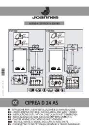
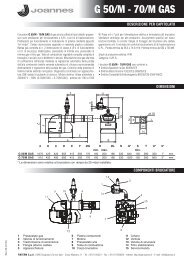
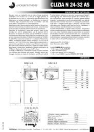
Ciprea <strong>20</strong>KeyBCDEGPressure pointModureg cableProtective capMinimum pressure adjustmentMaximum pressure adjustmentAfter checking or adjusting the pressure,it is mandatory to seal the adjustmentscrew with paint or a specific seal.Fig. 3Adjusting the maximum heating outputTo adjust the heating power, set the boiler on TEST operation (see par. 3.1). Turn the heating temperature controlknob (ref. 1 - fig. 1) clockwise to increase the power or anticlockwise to decrease it (see pressure/power diagramchap. 4.5). Exit TEST operation (see par. 3.1). The maximum heating power will remain as set during the TEST.Ignition power adjustmentTo adjust the ignition power, set the boiler on TEST operation (see par. 3.1).Turn the hot water temperature control knob (ref. 2 - fig. 1) clockwise to increase the power or anticlockwise to decreaseit (see pressure/power diagram chap. 4.5). Exit TEST operation (see par. 3.1). The ignition power will remainas set during the TEST.Installer parameters menuThe card has 10 transparent parameters that can be modified either by Remote Control (Service parameters menu)or by itself (8 from Installer Parameters Menu and 2 in Test Mode):Remote Control Parameters Menu Range Default Card menu1 (not used) / / /2 (Gas type selection) 0=Natural gas,1=LPG 0=Natural gas P13 (not used) / / /4 (Heating post-circulation pump) 1-<strong>20</strong> minutes 6 minutes P35 (Heating ramp) 1-<strong>20</strong>°C/min 5°C/min P56 (Maximum heating output) 0-100% 100% TEST mode7 (Heating stand-by time) 0-255 seconds 1<strong>20</strong>sec. P28 (Maximum hot water user setpoint) 0=55°C,1=60°C 0 P69 (Ignition power) 0-60% 50 % TEST mode10 (Maximum heating user setpoint) 30-85°C 85°C P411 (Switching off burner in hot water mode) 0=Fixed,1=Tied to setpoint 1=setp. P712 (Mains Voltage Frequency) 0=50Hz,1=60Hz 0=50Hz P8The Remote Timer Control is modified by entering its Service parameters menu (see relevant manual): the order andrange correspond exactly to the contents of the table.The card is modified in two ways.The Maximum Heating Output and Ignition Power parameters can be modified in Test Mode (see relevantparagraph).The parameters, designated P1‚P8 in the previous table, can be displayed and if necessary modified from the Installer24