DLK/ DLKT FKN/ FKNT UV/ UVT - Walter Roller GmbH & Co.
DLK/ DLKT FKN/ FKNT UV/ UVT - Walter Roller GmbH & Co.
DLK/ DLKT FKN/ FKNT UV/ UVT - Walter Roller GmbH & Co.

Create successful ePaper yourself
Turn your PDF publications into a flip-book with our unique Google optimized e-Paper software.
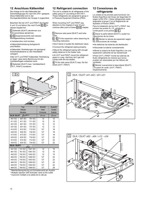
12 Anschluss Kältemittel<br />
Die Anlage ist für alle Kältemittel der<br />
Sicherheitsgruppe A2 nach EN 378-1 geeignet.<br />
Diese Kältemittel sind in der<br />
Druckgeräterichtlinie der Gruppe 2 zugeordnet.<br />
Beachten Sie bei <strong>UV</strong>/T und <strong>FKN</strong>/T die Kapitel<br />
9 und 10 und fahren Sie nach Punkt 2. / 3. in<br />
diesem Kapitel fort.<br />
1. Seitenteil (<strong>DLK</strong>/T) abnehmen und<br />
Rohrverschlüsse abnehmen.<br />
2. / 3. Expansionsventil nach dessen<br />
Montageanleitung montieren.<br />
12<br />
Verteilerrohre nicht knicken.<br />
Kältemittelrohrleitung fachgerecht<br />
anschließen.<br />
Kältemittel- Rohrleitungen mit genügend<br />
Sicherheitsabstand zu den Heizstäben<br />
verlegen!<br />
Bei <strong>UV</strong>/T und <strong>FKN</strong>/T Kältemittel- Rohrleitung<br />
so legen, dass keine Berührung mit den<br />
Ventilatorflügeln entstehen kann.<br />
4. Seitenteil (<strong>DLK</strong>/T) bzw. Ventilatorblech<br />
(<strong>UV</strong>/T, <strong>FKN</strong>/T) montieren.<br />
Typ Eintritt Austritt<br />
Model Inlet Outlet<br />
Modelo Entrada Salida<br />
<strong>DLK</strong>/ <strong>DLK</strong>T Ø mm Ø mm<br />
401 EC 601 EC 701 EC 12 12<br />
411 EC 611 EC 711 EC 12 12<br />
421 EC 621 EC 721 EC 12 12<br />
431 EC 631 EC 731 EC 12 12<br />
412 EC 612 EC 712 EC 12* 18<br />
432 EC 632 EC 732 EC 12* 18<br />
413 EC 613 EC 713 EC 12* 18<br />
433 EC 633 EC 733 EC 12* 22<br />
414 EC 614 EC 714 EC 12* 22<br />
434 EC 634 EC 734 EC 12* 22<br />
<strong>DLK</strong> / <strong>DLK</strong>T<br />
441 EC 741 EC 1041 EC 12 15<br />
461 EC 761 EC 1061 EC 12 15<br />
442 EC 742 EC 1042 EC 12 15<br />
462 EC 762 EC 1062 EC 12* 22<br />
443 EC 743 EC 1043 EC 12* 22<br />
463 EC 763 EC 1063 EC 12* 22<br />
444 EC 744 EC 1044 EC 12* 22<br />
464 EC 764 EC 1064 EC 12* 28<br />
* Mehrfacheinspritzung mit Schraderventil am Austritt<br />
* Multiple injection with Schrader valve at the outlet<br />
* Inyección múltiple a la salida de la válvula<br />
12 Refrigerant connection<br />
The unit is suitable for all refrigerants of the<br />
safety group A1 according to EN 378-1.<br />
These refrigerants are assigned to group 2<br />
in Pressure Equipment Directive (PED).<br />
When mounting <strong>UV</strong>/T and <strong>FKN</strong>/T pay<br />
attention to the chapters 9 and 10 and<br />
continue after point of these 2. / 3. chapter.<br />
1. Remove side panel (<strong>DLK</strong>/T) and tube<br />
seals.<br />
2. / 3. Fit the expansion valve observing its<br />
mounting instruction.<br />
Don’t bend or buckle the distributor tubes.<br />
<strong>Co</strong>nnect the refrigerant piping properly.<br />
Mount the refrigerant piping with enough<br />
safety distance to the heater rods.<br />
At <strong>UV</strong>/T and <strong>FKN</strong>/T mount the refrigerant<br />
pipes in a way, that they don’t get into<br />
contact with the fan blades.<br />
4. Fit the side panel (<strong>DLK</strong>/T) resp. the fan<br />
sheet (<strong>UV</strong>/T, <strong>FKN</strong>/T)<br />
12 <strong>Co</strong>nexiones de<br />
refrigerante<br />
La unidad se ha previsto para funcionar con<br />
fluidos frigoríficos del Grupo de Seguridad A1<br />
según la EN 378-1. Estos refrigerantes están<br />
asignados al grupo 2 en el Reglamento de<br />
Aparatos a Presion (RAP).<br />
Para la instalación de los <strong>UV</strong>/T y <strong>FKN</strong>/T, lea<br />
primero los puntos 9 y 10, volviendo a<br />
continuación a los puntos 2./ 3. .<br />
1. Sacar la parte lateral (<strong>DLK</strong>/T) y quitar los<br />
capuchones de los tubos.<br />
2. / 3. Montar la válvula de expansión según<br />
las instrucciones de montaje.<br />
No deformar las tuberías del distribuidor.<br />
Abocardar la tubería correctamente.<br />
Monte la tubería de fluido frigorífico con una<br />
separación suficiente de las resistencias!<br />
Para <strong>UV</strong>/T y <strong>FKN</strong>/T monte las tuberías de<br />
fluido refrigerante de manera que nunca<br />
puedan ser alcanzadas por las hélices del<br />
ventilador.<br />
4. Montar nuevamente la tapa lateral (<strong>DLK</strong>/T)<br />
y el panel de ventil. (<strong>UV</strong>/T, <strong>FKN</strong>/T)<br />
respectivamente.