Robbe Cardinal.pdf - RCtube.eu
Robbe Cardinal.pdf - RCtube.eu
Robbe Cardinal.pdf - RCtube.eu

Create successful ePaper yourself
Turn your PDF publications into a flip-book with our unique Google optimized e-Paper software.
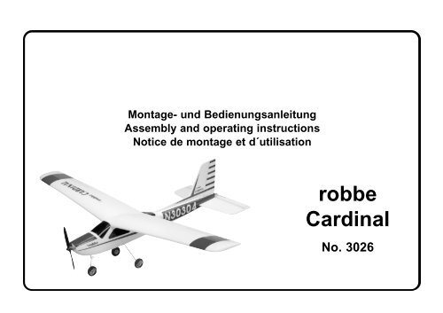
Montage- und Bedienungsanleitung<br />
Assembly and operating instructions<br />
Notice de montage et d´utilisation<br />
robbe<br />
<strong>Cardinal</strong><br />
No. 3026
Technische Daten<br />
Spannweite: ca. 1550 mm<br />
Gesamtflächeninhalt: ca. 36,7 dm 2<br />
Fluggewicht: ab 1550 g<br />
Gesamtflächenbelastung: ab 42,2 g/dm 2<br />
Nicht enthaltenes Zubehör siehe Beilageblatt<br />
Werkz<strong>eu</strong>ge siehe robbe Hauptkatalog<br />
Allgemeine Hinweise für den Bauablauf<br />
Die Numerierung entspricht im wesentlichen der<br />
Reihenfolge des Bauablaufs, wobei die Nummer vor dem<br />
Punkt die Baustufe, die Nummer hinter dem Punkt das<br />
betreffende Bauteil angibt.<br />
Verschaffen Sie sich in Verbindung mit den Abbildungen<br />
und Kurztexten, sowie der Stückliste einen Überblick über<br />
die jeweiligen Bauschritte.<br />
Richtungsangaben, wie z. Bsp. „rechts“ sind in<br />
Flugrichtung zu sehen.<br />
Besondere Hinweise zu dem Werkstoff Arcel<br />
Die <strong>Cardinal</strong> ist aus dem schlagzähen Formschaum<br />
Arcel gefertigt.<br />
Dies bed<strong>eu</strong>tet keine größeren Probleme beim Bau des<br />
Modells, jedoch müssen beim Kleben und der<br />
Oberflächenbehandlung einige werkstofftypische<br />
Eigenheiten beachtet werden.<br />
Verklebungen<br />
Klebearbeiten an Arcel-Formschaumteilen nur mit <strong>Robbe</strong>-<br />
Speed-Sekundenkleber ausführen.<br />
Bauanleitung, Assembly instructions, Notice de montage<br />
<strong>Cardinal</strong><br />
Specification<br />
Wingspan: approx. 1550 mm<br />
Total surface area: approx. 36.7 dm 2<br />
All-up weight: min. 1550 g<br />
Total surface area loading: min. 42.2 g/dm 2<br />
See separate sheet for details of accessories not<br />
included in the kit.<br />
Refer to the main robbe catalogue for modelling tools.<br />
Sequence of assembly<br />
In general terms the numbering of the kit components<br />
reflects the sequence of assembly; the number before the<br />
point indicates the Stage of construction, the number after<br />
the point the individual part.<br />
Please study the brief instructions, referring to the illustrations<br />
and the parts list, so that you have a clear idea how<br />
each stage of construction progresses.<br />
Directions such as „right-hand“ are as seen from the<br />
tail of the model looking forward.<br />
Working with Arcel<br />
The<strong>Cardinal</strong> is moulded in a tough, resilient foam called<br />
Arcel.<br />
This does not present any major problems when building<br />
the model, but some characteristics of the material must<br />
be borne in mind when gluing joints and finishing the surfaces.<br />
Glued joints<br />
Moulded Arcel foam components should always be glued<br />
using <strong>Robbe</strong> Speed cyano-acrylate („cyano“.<br />
2<br />
Caractéristiques techniques<br />
envergure : approx. 1550 mm<br />
surface alaire totale : approx. 36,7 dm 2<br />
poids en ordre de vol : à partir de 1550 g<br />
charge alaire totale: à partir de 42,2 g/dm 2<br />
No.<br />
3026<br />
Pour les accessoires non contenus dans la boîte de<br />
construction, reportez-vous au f<strong>eu</strong>illet joint.<br />
Outillage, cf. catalogue général robbe<br />
Consignes générales concernant le déroulement de la<br />
construction<br />
La numérotation des pièces correspond en règle générale<br />
à l<strong>eu</strong>r ordre d’intervention dans le montage ; le numéro<br />
devant le point désigne le stade de montage en cours et<br />
le numéro suivant le point désigne la pièce elle-même.<br />
Avant d’entreprendre l‘assemblage du modèle, lire la présente<br />
notice en vous référant aux illustrations et à la liste<br />
des pièces afin de vous faire une idée d’ensemble des<br />
diverses étapes de construction.<br />
Les indications directionnelles comme „droite“, par<br />
exemple, sont à considérer dans le sens du vol.<br />
Consignes particulières concernant le matériau de<br />
construction Arcel<br />
Le modèle <strong>Cardinal</strong>. est réalisé en mousse moulée résistant<br />
aux chocs Arcel.<br />
Cela signifie que la construction du modèle elle-même ne<br />
présente pas de gros problèmes, toutefois pour le collage<br />
et le traitement de surface, il faut tenir compte des spécificités<br />
du matériau.<br />
Collage<br />
Ne coller les éléments en mousse moulée Arcel qu’avec<br />
de la colle cyanoacrylate <strong>Robbe</strong>-Speed.
Zum Verkleben von Metall- oder Kunststoffteilen mit<br />
Formschaum ausschließlich Epoxy verwenden.<br />
Oberflächenbehandlung<br />
Die Farbgebung des Modells erfolgt mit den Dekorbildern.<br />
Arcel ist mit handelsüblichen Farben nicht lackierbar.<br />
Hinweise zur Fernst<strong>eu</strong>eranlage<br />
Als Fernst<strong>eu</strong>erung benötigen Sie eine Anlage ab 3<br />
Kanälen und 2 Servos sowie einen elektronischen<br />
Fahrtregler mit BEC - Funktion.<br />
Orientieren Sie sich vor Baubeginn über die<br />
Einbaumöglichkeit der zu verwendenden Fernst<strong>eu</strong>erung.<br />
Sollte eine andere, als die von uns vorgeschlagene<br />
St<strong>eu</strong>erung verwendet werden, können Sie sich nach dem<br />
Einbauschema richten. Maßdifferenzen sind von Ihnen<br />
selbst auszugleichen.<br />
Die Servos vor dem Einbau mit der Fernst<strong>eu</strong>erung in<br />
N<strong>eu</strong>tralstellung bringen (Knüppel und Trimmhebel am<br />
Sender in Mittelstellung).<br />
Zur Inbetriebnahme immer den Gasknüppel in Stellung<br />
„Motor aus“ bringen, den Sender einschalten. Erst dann<br />
den Akku anschließen.<br />
Zum Ausschalten immer die Verbindung Akku -<br />
Motorregler trennen, erst dann den Sender ausschalten.<br />
Hinweis zur Stückliste<br />
n. e. = nicht enthalten<br />
Bauanleitung, Assembly instructions, Notice de montage<br />
<strong>Cardinal</strong><br />
Use epoxy for all joints where metal or plastic parts are to<br />
be glued to the moulded foam components.<br />
Surface finishing<br />
The model is designed to be finished using the self-adhesive<br />
decals supplied. Arcel cannot be painted using standard<br />
commercially available paints.<br />
Radio control system<br />
You will need a radio control system with at least 3 channels<br />
and 2 servos, plus an electronic speed controller with<br />
integral BEC system.<br />
Ensure that your receiving system components will fit in<br />
the recommended positions before starting construction.<br />
If you prefer to use a system other than the one we<br />
recommend, you can still follow the overall installation<br />
plan, but you may need to make allowance for minor differences<br />
in component size.<br />
Before installing the receiving system set the servos to<br />
n<strong>eu</strong>tral (centre) from the transmitter (sticks and trims to<br />
centre).<br />
When flying the model it is important to keep to this<br />
sequence when you switch on: first set the throttle stick to<br />
the „motor off“ position, then switch on the transmitter.<br />
Only then connect the flight battery to the speed controller.<br />
At the end of a flight always disconnect the flight battery<br />
from the speed controller first, and only then switch off the<br />
transmitter.<br />
Abbreviations in the parts list<br />
N.I. = Not included<br />
3<br />
No.<br />
3026<br />
Pour coller les éléments en métal et en plastique avec la<br />
mousse moulée, utiliser exclusivement de la colle époxy.<br />
Traitement des surfaces<br />
La décoration du modèle est assurée par des autocollants.<br />
Arcel ne p<strong>eu</strong>t être mis en peinture avec les produits habituels.<br />
Remarques concernant l’ensemble de radiocommande<br />
Pour piloter le modèle, il faut disposer d’un ensemble de<br />
radiocommande à partir de 3 voies et d<strong>eu</strong>x servos de<br />
même que d’un variat<strong>eu</strong>r électronique équipe de la fonction<br />
BEC.<br />
Avant d’entreprendre la construction, tenir compte des<br />
possibilités d’implantation de l’ensemble de réception<br />
choisi.<br />
Si vous utilisez un autre ensemble de radiocommande<br />
que celui que nous recommandons, référez-vous au schéma<br />
d’implantation afin de compenser systématiquement<br />
les différences d‘encombrement.<br />
Avant de mettre les servos en place, les amener au n<strong>eu</strong>tre<br />
à l’aide de l’ensemble de radiocommande (manche et<br />
potentiomètre (trim) sur l’émett<strong>eu</strong>r en position médiane.<br />
Pour la mise en service du modèle, disposer systématiquement<br />
le manche des gaz en position „mot<strong>eu</strong>r arrêt“<br />
avant de mettre l’émett<strong>eu</strong>r en marche. Raccorder ensuite<br />
s<strong>eu</strong>lement l’accu du mot<strong>eu</strong>r.<br />
Pour couper, désolidariser toujours d’abord le variat<strong>eu</strong>r du<br />
mot<strong>eu</strong>r de l’accu du mot<strong>eu</strong>r puis couper l‘émett<strong>eu</strong>r.<br />
Remarques concernant la liste des pièces<br />
n. c. = non contenu dans la boîte de construction
1 2<br />
3<br />
1.3<br />
Bauanleitung, Assembly instructions, Notice de montage<br />
No.<br />
<strong>Cardinal</strong> 3026<br />
4<br />
4<br />
1.2<br />
1.3<br />
1.1, 1.2<br />
1.1
Bild 1<br />
Hinweis zu den Angüssen: Alle Angüsse an den Arcel-<br />
Teilen mit einem scharfen Messer entfernen<br />
Baustufe 1, die Tragfläche<br />
Nr. Bezeichnung, Maße in mm Stück<br />
1.1 Tragflächenhälfte rechts 1<br />
1.2 Tragflächenhälfte links 1<br />
1.3 Hütchen (Lochverstärkung) 1<br />
Bild 2<br />
- Die Tragflächenhälften 1.1 und 1.2 mit Sekundenkleber<br />
und Aktivator deckungsgleich zusammenkleben.<br />
Bild 3<br />
- Das Hütchen 1.3 als Auflage für die<br />
Tragflächenschraube mit Sekundenkleber einkleben.<br />
Das Hütchen ist aus Darstellungsgründen schwarz eingefärbt.<br />
Bild 4<br />
- Die Bohrung in der Tragfläche durch das Hütchen mit<br />
einer Rundfeile auffeilen.<br />
Bauanleitung, Assembly instructions, Notice de montage<br />
<strong>Cardinal</strong><br />
Fig. 1<br />
Note - moulding flash: remove all excess material attached<br />
to the Arcel components using a sharp knife.<br />
Stage 1, the wing<br />
No. Description, size in mm No. off<br />
1.1 Right wing panel 1<br />
1.2 Left wing panel 1<br />
1.3 Top-hat bush (hole reinforcement) 1<br />
Fig. 2<br />
- Glue the wing panels 1.1 and 1.2 together using cyano<br />
and activator. Take care to keep all edges and faces<br />
flush.<br />
Fig. 3<br />
- Glue the top-hat bush 1.3 in the hole for the wing retainer<br />
screw, where it acts as a reinforcement. The bush is<br />
shown black for clarity.<br />
Fig. 4<br />
- Continue the hole right through the wing by twisting a<br />
round file through the top-hat bush.<br />
5<br />
Fig. 1<br />
No.<br />
3026<br />
Recommandation concernant les bavures d’injection :<br />
ébarber tous les éléments en Arcel à l’aide d’un couteau<br />
bien aiguisé<br />
Stade 1,l’aile<br />
N° Désignation, cotes en mm Nbre de pièces<br />
1.1 demi-aile droite 1<br />
1.2 demi-aile gauche 1<br />
1.3 calotte (renfort d’alésage) 1<br />
Fig. 2<br />
- Coller les demi-ailes 1.1 et 1.2 exactement ensemble<br />
avec de la colle cyanoacrylate et un activat<strong>eu</strong>r.<br />
Fig. 3<br />
- Coller la calotte 1.3 comme embout pour la vis de l’aile<br />
avec de la colle cyanoacrylate.<br />
Pour des raisons de lisibilité, la calotte est représentée<br />
en noir.<br />
Fig. 4<br />
- Limer l’orifice dans l’aile au travers de la calotte à l’aide<br />
d’une lime ronde.
5 6 7<br />
2.1<br />
8 9 10<br />
2.2<br />
Bauanleitung, Assembly instructions, Notice de montage<br />
No.<br />
<strong>Cardinal</strong> 3026<br />
2.1<br />
2.2 2.4<br />
2.3 2.5<br />
6<br />
2.1<br />
2.6
Baustufe 2, der Antrieb<br />
Nr. Bezeichnung, Maße in mm Stück<br />
2.1 Rumpf1<br />
2.2 E - Motor 1<br />
2.3 Regler 1, n.e.<br />
2.4 Lüsterklemme 1<br />
2.5 Schraube, M 3 x 8 2<br />
2.6 Motorspant 1<br />
2.7 Motorhaubendeckel 1<br />
Bild 5 - 7<br />
- Den Frischluftkanal und den Abluftkanal zur Kühlung<br />
von Motor und Regler mit einer Rundfeile im Rumpfkopf<br />
(Rumpf 2.1) ausarbeiten.<br />
Bild 8<br />
- Die Anschlußkabel des Motors 2.2 auf 4 cm, die weißblauen<br />
Motoranschlußkabel des Reglers 2.3 auf 7 cm<br />
kürzen und ca. 6 mm abisolieren.<br />
Bild 9<br />
- Den Regler 2.3 mittels Lüsterklemme 2.4 mit dem<br />
Motor verbinden, wobei das rote Motorkabel am weißen<br />
Reglerkabel, das schwarze Kabel am blauen Kabel<br />
angeschlossen wird.<br />
Bild 10<br />
- Den Motor mit den Schrauben 2.5 am Motorspant 2.6<br />
verschrauben.<br />
Bauanleitung, Assembly instructions, Notice de montage<br />
<strong>Cardinal</strong><br />
Stage 2, the power system<br />
No. Description, size in mm No. off<br />
2.1 Fuselage 1<br />
2.2 Electric motor 1<br />
2.3 Speed controller 1, N.I.<br />
2.4 Terminal block 1<br />
2.5 Screw, M3 x 8 2<br />
2.6 Motor bulkhead 1<br />
2.7 Motor cowl cover 1<br />
Figs. 5 - 7<br />
- Cut the air inlet and exit ducts in the fuselage nose<br />
(fuselage 2.1) using a round file. They are required to<br />
cool the motor and speed controller.<br />
Fig. 8<br />
- Cut down the power leads attached to the motor 2.2 to<br />
a length of 4 cm, and the white/blue motor leads attached<br />
to the speed controller 2.3 to 7 cm. Strip about 6<br />
mm of insulation from the wire ends.<br />
Fig. 9<br />
- Connect the speed controller 2.3 to the motor using the<br />
terminal block 2.4. The red motor wire should be<br />
connected to the white controller wire, the black wire to<br />
the blue wire.<br />
Fig. 10<br />
- Fix the motor to the motor bulkhead 2.6 using the<br />
screws 2.5.<br />
7<br />
Stade 2, l‘entraînement<br />
No.<br />
3026<br />
N° Désignation, cotes en mm Nbre de pièces<br />
2.1 fuselage 1<br />
2.2 mot<strong>eu</strong>r électrique 1<br />
2.3 variat<strong>eu</strong>r 1, n.c.<br />
2.4 domino 1<br />
2.5 vis, M 3 x 8 2<br />
2.6 couple-mot<strong>eu</strong>r 1<br />
2.7 couvercle du capot-mot<strong>eu</strong>r 1<br />
Fig. 5 à 7<br />
- Dans le nez du fuselage, à l’aide d’une lime ronde, limer<br />
l’entrée d’air frais et la sortie de l’air pour le refroidissement<br />
du mot<strong>eu</strong>r (fuselage 2.1).<br />
Fig. 8<br />
- Réduire le cordon de connexion du mot<strong>eu</strong>r 2.2 à 4 cm et<br />
raccourcir le cordon vers le mot<strong>eu</strong>r, blanc-bl<strong>eu</strong>, du variat<strong>eu</strong>r<br />
2.3 à 7 cm et en retirer la gaine isolante sur 6 mm<br />
environ.<br />
Fig. 9<br />
- Raccorder le variat<strong>eu</strong>r 2.3 à l’aide du domino 2.4 au<br />
mot<strong>eu</strong>r, le brin rouge du mot<strong>eu</strong>r devant être raccordé au<br />
brin blanc du variat<strong>eu</strong>r, le brin noir du mot<strong>eu</strong>r au brin<br />
bl<strong>eu</strong> du variat<strong>eu</strong>r.<br />
Fig. 10<br />
- À l’aide des vis 2.5 fixer le mot<strong>eu</strong>r au couple-mot<strong>eu</strong>r 2.6.
11<br />
13<br />
(2.3)<br />
2.1<br />
Bauanleitung, Assembly instructions, Notice de montage<br />
No.<br />
<strong>Cardinal</strong> 3026<br />
2.6<br />
8<br />
12<br />
14<br />
2.3<br />
2.7
Bild 11<br />
- Die Einheit in den Rumpf 2.1 setzen und ausrichten. Bei<br />
korrektem Sitz den Motorspant 2.6 am Rumpfkopf verkleben.<br />
Bild 12<br />
- Den Regler 2.3 hinter dem Motor platzieren. Akku-<br />
Anschlußkabel und Empfängerkabel des Reglers im<br />
Schacht nach hinten führen.<br />
Bild 13<br />
- Das Akku-Anschlußkabel des Reglers wird nach unten<br />
zum Akkuschacht verlegt.<br />
Bild 14<br />
- Den Motorhaubendeckel 2.7 aufsetzen und mit einem<br />
Streifen Klebeband fixieren. Die endgültige Befestigung<br />
erfolgt nach der Funktionsprobe mit dem Dekorteil - A.<br />
Bauanleitung, Assembly instructions, Notice de montage<br />
<strong>Cardinal</strong><br />
Fig. 11<br />
- Place the motor assembly in the fuselage 2.1 and align<br />
it carefully. When you are confident of its position, glue<br />
the motor bulkhead 2.6 to the fuselage nose.<br />
Fig. 12<br />
- Install the speed controller 2.3 immediately behind the<br />
motor. Route the battery leads and receiver lead attached<br />
to the controller towards the rear, pushing them<br />
into the slot provided.<br />
Fig. 13<br />
- Run the battery leads attached to the speed controller<br />
down through the fuselage and into the battery well.<br />
Fig. 14<br />
- Place the motor cowl cover 2.7 on the fuselage and<br />
secure it with a strip of adhesive tape. It is attached permanently<br />
using decal A once you have checked the working<br />
systems.<br />
9<br />
Fig. 11<br />
No.<br />
3026<br />
- Installer l’unité dans le fuselage 2.1 et l’y centrer.<br />
Lorsque l’assise est correcte, coller le couple-mot<strong>eu</strong>r<br />
2.6 au nez du fuselage.<br />
Fig. 12<br />
- Disposer le variat<strong>eu</strong>r 2.3 derrière le mot<strong>eu</strong>r. Amener le<br />
cordon de connexion à l’accu et le cordon de réception<br />
du variat<strong>eu</strong>r vers l’arrière dans le logement.<br />
Fig. 13<br />
- Disposer le cordon de connexion de l’accu du variat<strong>eu</strong>r<br />
vers le bas, en direction du compartiment de l‘accu.<br />
Fig. 14<br />
- Mettre le couvercle du capot-mot<strong>eu</strong>r 2.7 en place et le<br />
fixer avec un morceau de ruban adhésif. La fixation<br />
définitive n’interviendra qu’après les essais de fonctionnement<br />
à l’aide de l’élément de décoration - A.
15<br />
3.6<br />
30°<br />
17 18<br />
3.5<br />
3.2<br />
3.1<br />
Bauanleitung, Assembly instructions, Notice de montage<br />
No.<br />
<strong>Cardinal</strong> 3026<br />
3.3<br />
10<br />
16<br />
3.3<br />
3.7<br />
3.4
Baustufe 3, RC-Einbau<br />
Nr. Bezeichnung, Maße in mm Stück<br />
3.1 Höhenruderservo 1, n.e.<br />
3.2 Seitenruderservo 1, n.e.<br />
3.3 Höhenrudergestänge, eins. Z, Ø 1,2 x 570 1<br />
3.4 Seitenrudergestänge, eins. Z, Ø 1,2 x 570 1<br />
3.5 Führungsröhrchen, Höhe, Ø 3,2 x 430 1<br />
3.6 Führungsröhrchen, Seite, Ø 3,2 x 320 1<br />
3.7 Empfänger 1, n.e.<br />
Bild 15<br />
- Servos 3.1 und 3.2 in die Servoschächte des Rumpfs<br />
einsetzen, dabei die Kabel nach vorn zum<br />
Empfängerschacht führen. Servos mit einigen Tropfen<br />
Epoxy sichern. St<strong>eu</strong>erscheibe vom Höhenruderservo<br />
demontieren.<br />
- Die Servos mit der Fernst<strong>eu</strong>erung in N<strong>eu</strong>tralstellung<br />
bringen.<br />
- Das Höhenrudergestänge 3.3 von unten in der<br />
St<strong>eu</strong>erscheibe einhängen. Führungsröhrchen 3.5 aufschieben.<br />
St<strong>eu</strong>erscheibe so aufstecken, daß sich etwa<br />
ein Winkel von 30° zur Mittenposition ergibt.<br />
Bilder 16 und 17<br />
- Das Höhenrudergestänge 3.3 so nach hinten führen,<br />
daß es am Rumpfende mittig austritt.<br />
- Das Seitenrudergestänge 3.4 von oben in der<br />
St<strong>eu</strong>erscheibe einhängen, mit Führungsröhrchen 3.6<br />
versehen und nach hinten zum rechten Rumpfaustritt<br />
verlegen.<br />
- Das Höhenrudergestänge befindet sich unten.<br />
Bild 18<br />
- Die Litzenantenne des Empfängers 3.7 abwickeln.<br />
- Regler und Servos an den entsprechenden<br />
Empfängerkanälen anschließen.<br />
- Den Empfänger in den Empfängerschacht eindrücken.<br />
Die Litzenantenne wird bei Fertigstellung des Modells<br />
zum Seitenleitwerk verlegt. Der Führungsröhrchen-Rest<br />
kann zum Verlegen der Antenne im Rumpf verwendet<br />
werden.<br />
Bauanleitung, Assembly instructions, Notice de montage<br />
<strong>Cardinal</strong><br />
Stage 3, RC installation<br />
No. Description, size in mm No. off<br />
3.1 Elevator servo 1, N.I.<br />
3.2 Rudder servo 1, N.I.<br />
3.3 Elev. pushrod, one Z-bend, 1.2 Ø x 570 1<br />
3.4 Rudder pushrod, one Z-bend, 1.2 Ø x 570 1<br />
3.5 Elevator pushrod sleeve, 3.2 Ø x 430 1<br />
3.6 Rudder pushrod sleeve, 3.2 Ø x 320 1<br />
3.7 Receiver 1, N.I.<br />
Fig. 15<br />
- Place the servos 3.1 and 3.2 in the servo wells in the<br />
fuselage, and run the leads forward to the receiver bay.<br />
Secure each servo with a few drops of epoxy. Remove<br />
the output disc from the elevator servo.<br />
- Set the servos to n<strong>eu</strong>tral (centre) from the transmitter.<br />
- Connect the pre-formed end of the elevator pushrod 3.3<br />
to the servo output disc from the underside. Slip the pushrod<br />
sleeve 3.5 onto the pushrod. Fit the output disc on<br />
the servo, angled back by about 30º as shown.<br />
Figs. 16 and 17<br />
- Run the elevator pushrod 3.3 back until it exits the tail<br />
end of the fuselage in the centre.<br />
- Connect the rudder pushrod 3.4 to the output disc from<br />
the top, slip the pushrod sleeve onto it and route it down<br />
the fuselage to the tail end, exiting the fuselage through<br />
the right-hand slot.<br />
- The elevator pushrod should be underneath the rudder<br />
pushrod.<br />
Fig. 18<br />
- Unwind the flexible aerial attached to the receiver 3.7.<br />
- Connect the speed controller and servos to the appropriate<br />
receiver sockets.<br />
- Push the receiver into the receiver bay. During the final<br />
stages of construction the receiver aerial will be routed<br />
to the fin. Fit the remaining piece of pushrod sleeve in<br />
the fuselage and run the receiver aerial through it.<br />
11<br />
No.<br />
3026<br />
Stade 3, mise en place de l’ensemble de réception<br />
N° Désignation, cotes en mm Nbre de pièces<br />
3.1 servo de la gouverne de profond<strong>eu</strong>r 1, n.c.<br />
3.2 servo de la gouverne de direction 1, n.c.<br />
3.3 tringle, profond<strong>eu</strong>r, un. Z, Ø 1,2 x 570 1<br />
3.4 tringle, direction, un. Z, Ø 1,2 x 570 1<br />
3.5 tube-guide, profond<strong>eu</strong>r, Ø 3,2 x 430 1<br />
3.6 tube-guide, direction, Ø 3,2 x 320 1<br />
3.7 récept<strong>eu</strong>r 1, n.c.<br />
Fig. 15<br />
- Installer les servos 3.1 et 3.2 dans les logements de<br />
servo du fuselage en tirant le cordon vers l’avant vers le<br />
compartiment du récept<strong>eu</strong>r. Fixer le servo avec quelques<br />
gouttes de colle époxy. Démonter le palonnier circulaire<br />
du servo de la gouverne de profond<strong>eu</strong>r.<br />
- Amener les servos au n<strong>eu</strong>tre à l’aide de l’ensemble de<br />
radiocommande.<br />
- Accrocher la tringle de la gouverne de profond<strong>eu</strong>r 3.3<br />
par-dessous au palonnier circulaire. Mettre le tubeguide<br />
3.5 en place. Mettre le palonnier circulaire en<br />
place de telle manière à ce qu’un angle de 30° environ<br />
apparaisse par rapport à la position médiane.<br />
Fig. 16 et 17<br />
- Amener la tringle de la gouverne de profond<strong>eu</strong>r 3.3 vers<br />
l’arrière de sorte qu’elle réapparaisse au mili<strong>eu</strong> de la<br />
qu<strong>eu</strong>e du fuselage. Accrocher la tringle de la gouverne<br />
de direction 3.4 par le haut dans le palonnier circulaire,<br />
la munir du tube-guide 3.6 et la disposer vers l’arrière<br />
vers la sortie droite de la qu<strong>eu</strong>e du fuselage. La tringle<br />
de la gouverne de profond<strong>eu</strong>r se trouve en bas.<br />
Fig. 18<br />
- Développer l’antenne souple du récept<strong>eu</strong>r 3.7.<br />
- Raccorder le variat<strong>eu</strong>r et les servos aux voies correspondantes<br />
du récept<strong>eu</strong>r. Pousser le récept<strong>eu</strong>r dans le<br />
compartiment du récept<strong>eu</strong>r. Lorsque le modèle sera terminé,<br />
l’antenne souple du récept<strong>eu</strong>r sera disposée vers<br />
la dérive. Le reste du tube-guide p<strong>eu</strong>t être employé pour<br />
disposer l’antenne dans le fuselage.
19<br />
22<br />
4.2<br />
4.1, 4.2<br />
4.1<br />
20<br />
4.5, (4.6)<br />
4.5<br />
Bauanleitung, Assembly instructions, Notice de montage<br />
No.<br />
<strong>Cardinal</strong> 3026<br />
4.3<br />
12<br />
23<br />
21<br />
4.1, 4.2<br />
4.6<br />
4.5, (4.6)<br />
90°<br />
4.4
Baustufe 4, die Leitwerke<br />
Nr. Bezeichnung, Maße in mm Stück<br />
4.1 Bolzen, Stiftscharnier 7<br />
4.2 Auge, Stiftscharnier 7<br />
4.3 Höhenruder 1<br />
4.4 Seitenruder 1<br />
4.5 Höhenleitwerk 1<br />
4.6 Seitenleitwerk mit Formteil 1<br />
4.7 Ruderhorn 2<br />
4.8 Schraube, M 2 x 6 2<br />
4.9 Gestängekupplung 2<br />
Bild 19<br />
- Die Stiftscharniere aus den Bolzen 4.1 und den Augen<br />
4.2 zusammensetzen. Das Gelenk gegen Verkleben mit<br />
einem Tropfen Öl schützen.<br />
Bilder 20 und 21<br />
- Das Höhenruder 4.3 und das Seitenruder 4.4 mit einem<br />
scharfen Messer und einem Stahllineal nach<br />
Markierungen gerade abtrennen.<br />
- Die Schnittkanten verputzen.<br />
Bild 22<br />
- Gemäß den halbrunden Anformungen in den Leitwerken<br />
4.5 und 4.6 mit einem Stichling die Löcher für die<br />
Scharniere mittig mit Ø 2 mm vorstechen.<br />
Bild 23<br />
- Epoxy mit einem Drähtchen oder einer dicken Nadel in<br />
die Löcher träufeln.<br />
- Die Scharniere bis zum Gelenkanschlag einschieben.<br />
Scharniere nach oben drehen, um zu prüfen, daß sie<br />
rechtwinklig zur Mittellinie stehen.<br />
- Achtung: Es darf kein Kleber in die<br />
Scharnierdrehpunkte gelangen.<br />
Bauanleitung, Assembly instructions, Notice de montage<br />
<strong>Cardinal</strong><br />
Stage 4, the tail panels<br />
No. Description, size in mm No. off<br />
4.1 Point hinge, male 7<br />
4.2 Point hinge, female 7<br />
4.3 Elevator 1<br />
4.4 Rudder 1<br />
4.5 Tailplane 1<br />
4.6 Fin and strake 1<br />
4.7 Horn 2<br />
4.8 Screw, M2 x 6 2<br />
4.9 Pushrod connector 2<br />
Fig. 19<br />
- Assemble the point hinges from the male parts 4.1 and<br />
the female parts 4.2. Apply a tiny drop of oil to the pivots<br />
to prevent glue jamming them.<br />
Figs. 20 and 21<br />
- Separate the elevator 4.3 from the tailplane by cutting<br />
along the marked line using a sharp balsa knife and a<br />
steel ruler. Separate the rudder 4.4 from the fin in the<br />
same way.<br />
- Carefully clean up the cut edges.<br />
Fig. 22<br />
- Pierce 2 mm Ø holes for the point hinges in the centre<br />
of the semi-circular recesses in the tailplane 4.5 and fin<br />
4.6 using a bradawl.<br />
Fig. 23<br />
- Apply epoxy to the inside of the holes using a piece of<br />
wire or a large pin.<br />
- Push the hinges into the holes as far as the pivot. Fold<br />
the hinges upwards to check that they are at rightangles<br />
to the centreline.<br />
- Caution: take care to avoid glue getting onto the hinge<br />
pivots.<br />
13<br />
Stade 4, les empennages<br />
No.<br />
3026<br />
N° Désignation, cotes en mm Nbre de pièces<br />
4.1 axe, charnière 7<br />
4.2 œillet, charnière 7<br />
4.3 gouverne de profond<strong>eu</strong>r 1<br />
4.4 gouverne de direction 1<br />
4.5 stabilisat<strong>eu</strong>r 1<br />
4.6 dérive avec élément formé 1<br />
4.7 guignol 2<br />
4.8 vis, M 2 x 6 2<br />
4.9 accouplement de tringle 2<br />
Fig. 19<br />
- Assembler les charnière à partir des axes 4.1 et des œillets<br />
4.2. Protéger l’articulation colle le collage éventuel<br />
par une goutte d‘huile.<br />
Fig. 20 et 21<br />
- Couper avec précision la gouverne de profond<strong>eu</strong>r 4.3 et<br />
la gouverne de direction 4.4 à l’aide d’un couteau bien<br />
aiguisé et d’une règle en métal en fonction des repères.<br />
- Nettoyer les arêtes de coupe.<br />
Fig. 22<br />
- Dans les concavités semi-circulaires dans les empennages<br />
4.5 et 4.6, à l’aide d’un poinçon, prépercer les<br />
trous des charnières, au centre, avec un diamètre de 2<br />
mm environ.<br />
Fig. 23<br />
- Appliquer de la colle époxy à l’aide d’un brin métallique<br />
ou d’une grosse aiguille dans les trous.<br />
- Mettre les charnières en place jusqu’à la butée de l‘articulation.<br />
- Tourner les charnières vers le haut afin de vérifier qu’elles<br />
se trouvent parfaitement perpendiculaires à la ligne<br />
médiane. Attention : la colle ne doit en aucun cas<br />
atteindre le pivot des charnières.
24 25<br />
26<br />
4.5<br />
Bauanleitung, Assembly instructions, Notice de montage<br />
No.<br />
<strong>Cardinal</strong> 3026<br />
4.3<br />
14<br />
27<br />
4.4<br />
4.6<br />
4.5
Bilder 24 und 25<br />
- Löcher für die Scharniere im Höhenruder 4.3 und<br />
Seitenruder 4.4 wie bei den Leitwerken vorstechen.<br />
- Die Ruder probeweise ansetzen, leichte Beweglichkeit<br />
prüfen.<br />
Bild 26<br />
- In die Scharnierbohrungen der Ruder Epoxy einträufeln<br />
und Ruder ansetzen. Auf ausreichende Ausschläge achten.<br />
Bild 27<br />
- Das Höhenleitwerk 4.5 probeweise auf die Einformung<br />
am Rumpfheck setzen, genauen Sitz kontrollieren.<br />
- Höhenleitwerk mit Sekundenkleber aufkleben.<br />
Bauanleitung, Assembly instructions, Notice de montage<br />
<strong>Cardinal</strong><br />
Figs. 24 and 25<br />
- Pierce holes for the hinges in the elevator 4.3 and rudder<br />
4.4 as described for the tailplane and fin.<br />
- Push the control surfaces onto the hinges and check<br />
that they deflect freely to both sides of centre.<br />
Fig. 26<br />
- Apply a little epoxy to the inside of the hinge holes in the<br />
rudder and elevator and push them onto the hinges.<br />
Check that they have plenty of movement to both sides.<br />
Fig. 27<br />
- Place the tailplane 4.5 temporarily in the moulded-in<br />
recess at the tail end of the fuselage, and check that it<br />
fits correctly.<br />
- Glue the tailplane to the fuselage using cyano.<br />
15<br />
Fig. 24 et 25<br />
No.<br />
3026<br />
- Prépercer les trous des charnières dans la gouverne de<br />
profond<strong>eu</strong>r 4.3 et dans la gouverne de direction 4.4<br />
comme décrit ci-dessus pour les empennages.<br />
- Mettre les gouvernes en place pour effectuer des essais<br />
de souplesse.<br />
Fig. 26<br />
- Appliquer de la colle époxy dans les orifices des charnières<br />
des gouvernes et mettre les gouvernes en place.<br />
Veiller à ce que les gouvernes présentent un débattement<br />
suffisant.<br />
Fig. 27<br />
- Installer le stabilisat<strong>eu</strong>r 4.5 pour en relever la position<br />
sur la concavité de l’arrière du fuselage, veiller à ce que<br />
son assise soit parfaite.<br />
- Coller le stabilisat<strong>eu</strong>r avec de la colle cyanoacrylate.
28 29<br />
31 32<br />
4.9<br />
4.6<br />
3.6<br />
Bauanleitung, Assembly instructions, Notice de montage<br />
No.<br />
<strong>Cardinal</strong> 3026<br />
16<br />
Ø 2 mm<br />
4.7<br />
30<br />
4.8<br />
4.9<br />
4.9
Bild 28<br />
- Das Seitenleitwerk 4.6 mit Formteil aufsetzen und korrekten,<br />
rechtwinkligen Sitz zum Höhenleitwerk prüfen.<br />
- Das Seitenleitwerk in der Rumpfsicke verkleben. Das<br />
Führungsröhrchen 3.6 wird dabei mitverklebt.<br />
Bilder 29 und 30<br />
- Die Ruderhörner 4.7 auf Ø 2 mm aufbohren. Die<br />
Gestängekupplungen 4.9 mit den Schrauben 4.8 an den<br />
Ruderhörnern montieren. Für Höhenruder: äußeres<br />
Loch; für Seitenruder: inneres Loch.<br />
Bild 31<br />
- Gestängekupplungen auf die Gestänge schieben.<br />
Ruderhörner in die entsprechenden Bohrungen der<br />
Ruder einsetzen, ausrichten und verkleben.<br />
- Achtung: Das Ruderhorn des Höhenruders weist nach<br />
hinten.<br />
Bild 32<br />
- Die Ruder auf Mittelstellung bringen und die Schrauben<br />
der Gestängekupplungen anziehen.<br />
- Überstehende Gestängeenden ca. 5 mm hinter den<br />
Kupplungen kürzen.<br />
Bauanleitung, Assembly instructions, Notice de montage<br />
<strong>Cardinal</strong><br />
Fig. 28<br />
- Place the fin and strake 4.6 on the fuselage and check<br />
that it is at right-angles to the tailplane.<br />
- Glue the fin in the slot in the fuselage, glue the pushrod<br />
sleeve 3.6 in place at the same time.<br />
Figs. 29 and 30<br />
- Drill out the linkage holes in the horns 4.7 to 2 mm Ø.<br />
Attach the pushrod connectors 4.9 to the horns using<br />
the screws 4.8. Use the outer hole for the elevator, the<br />
inner hole for the rudder.<br />
Fig. 31<br />
- Slip the pushrod connectors onto the pushrods. Fit the<br />
horns in the holes in the control surfaces, check alignment<br />
and glue them in place.<br />
- Caution: the elevator horn must face backwards.<br />
Fig. 32<br />
- Set the control surfaces to centre and tighten the screws<br />
in the pushrod connectors.<br />
- Snip off excess pushrod length about 5 mm aft of the<br />
pushrod connectors.<br />
17<br />
Fig. 28<br />
No.<br />
3026<br />
- Mettre la dérive 4.6 en place avec l’élément formé et en<br />
contrôler l’assise et l’angle droit par rapport au stabilisat<strong>eu</strong>r.<br />
- Coller la dérive dans la gorge du fuselage. Le tubeguide<br />
3.6 est collé simultanément.<br />
Fig. 29 et 30<br />
- Agrandir les trous des guignols 4.7 à Ø 2 mm. Monter<br />
les accouplements de tringle 4.9 avec les vis 4.8 sur les<br />
guignols. Pour la gouverne de profond<strong>eu</strong>r : trou le plus<br />
extéri<strong>eu</strong>r ; pour la gouverne de direction : trou les plus à<br />
l‘intéri<strong>eu</strong>r.<br />
Fig. 31<br />
- Glisser les accouplements de tringles sur la tringle.<br />
Installer les guignols dans les trous appropriés de la<br />
gouverne, les aligner et les coller.<br />
- Attention : le guignol de la gouverne de profond<strong>eu</strong>r est<br />
dirigé vers l‘arrière.<br />
Fig. 32<br />
- Amener les gouvernes au n<strong>eu</strong>tre et serrer les vis des<br />
accouplements de tringles.<br />
- Couper les saillies des extrémités des tringles, 5 mm<br />
approximativement à l’arrière des accouplements.
33 34<br />
5.3<br />
5.1<br />
35 36<br />
5.2<br />
5.2<br />
5.3<br />
Bauanleitung, Assembly instructions, Notice de montage<br />
No.<br />
<strong>Cardinal</strong> 3026<br />
18<br />
5.5, 5.6<br />
5.4<br />
5.5, 5.6<br />
5.1<br />
5.5, 5.6
Baustufe 5, das Fahrwerk<br />
Nr. Bezeichnung, Maße in mm Stück<br />
5.1 Bugfahrwerk 1<br />
5.2 Hauptfahrwerk 1<br />
5.3 Befestigungsstopfen 6<br />
5.4 Rad Ø 51 3<br />
5.5 Stellring Ø 3 x Ø 7 x 5 6<br />
5.6 Madenschraube M 3 x 3 6<br />
- Hinweis: Das Modell ist mit Dreibeinfahrwerk für sichere<br />
Bodenstarts und Landungen konzipiert. Wenn nur<br />
aus der Hand gestartet und auf einer Wiese gelandet<br />
wird, kann das Fahrwerk weggelassen werden. Durch<br />
das verringerte Gewicht und den verringerten<br />
Luftwiderstand werden die Flugleistungen dadurch<br />
sogar etwas verbessert. Die Flugcharakteristik ähnelt<br />
dann mehr derjenigen eines Motorseglers.<br />
Bild 33<br />
- Bug- und Hauptfahrwerksdraht 5.1 und 5.2 jeweils mit<br />
3 Befestigungsstopfen 5.3 versehen.<br />
Bild 34<br />
- Die Befestigungsbolzen des Bugfahrwerks mit Epoxy<br />
im Rumpf verkleben.<br />
Bild 35<br />
- Die Befestigungsbolzen des Hauptfahrwerks mit Epoxy<br />
im Rumpf verkleben.<br />
Bild 36<br />
- Die Räder 5.4 mit den Stellringen 5.5 mit<br />
Madenschrauben 5.6 leicht drehbar sichern.<br />
Bauanleitung, Assembly instructions, Notice de montage<br />
<strong>Cardinal</strong><br />
Stage 5, the undercarriage<br />
No. Description, size in mm No. off<br />
5.1 Noseleg unit 1<br />
5.2 Main undercarriage 1<br />
5.3 Retaining plugs 6<br />
5.4 Wheel, 51 Ø 3<br />
5.5 Collet, 3 Ø x 7 Ø x 5 6<br />
5.6 Grubscrew, M3 x 3 6<br />
- Note: the model features a tricycle undercarriage which<br />
provides reliable ground take-off and landing. If you<br />
intend only to hand-launch the model, and are able to<br />
land it on a grassy field, you can omit the undercarriage<br />
completely. The reduced weight and drag results in a<br />
slight improvement to the model’s performance in the<br />
air. Its flight characteristics are then similar to those of a<br />
powered glider.<br />
Fig. 33<br />
- Fit three retaining plugs 5.3 onto the noseleg unit 5.1<br />
and three more on the main undercarriage unit 5.2.<br />
Fig. 34<br />
- Epoxy the noseleg retaining plugs in the fuselage.<br />
Fig. 35<br />
- Epoxy the main undercarriage retaining plugs in the<br />
fuselage.<br />
Fig. 36<br />
- Fix the wheels 5.4 on the axles using the collets 5.5 and<br />
grubscrews 5.6. Ensure that the wheels rotate freely.<br />
19<br />
Stade 5, l’atterriss<strong>eu</strong>r<br />
No.<br />
3026<br />
N° Désignation, cotes en mm Nbre de pièces<br />
5.1 atterriss<strong>eu</strong>r avant 1<br />
5.2 atterriss<strong>eu</strong>r principal 1<br />
5.3 bouchon de fixation 6<br />
5.4 roue Ø 51 3<br />
5.5 bague d’arrêt Ø 3 x Ø 7 x 5 6<br />
5.6 vis sans tête M 3 x 3 6<br />
- À noter : le modèle est conçu avec un train d’atterrissage<br />
à trois jambes afin qu’il soit plus stable pour les<br />
décollages et les atterrissages du sol. Si l’appareil ne<br />
doit être lancé qu’à la main pour atterrir dans l’herbe<br />
d’une prairie, il est possible de faire l’impasse sur le train<br />
d‘atterrissage. L’avion présentera ainsi de meill<strong>eu</strong>res<br />
performances en vol grâce à un poids réduit et une résistance<br />
à l’air inféri<strong>eu</strong>re. Les caractéristiques de vol sont<br />
alors semblables à celle d’un motoplan<strong>eu</strong>r.<br />
Fig. 33<br />
- Munir les cordes à piano de l’atterriss<strong>eu</strong>r avant et de<br />
l‘atterriss<strong>eu</strong>r principal 5.1 et 5.2 chacun de 3 bouchons<br />
de fixation 5.3.<br />
Fig. 34<br />
- Coller les axes de fixation de l‘atterriss<strong>eu</strong>r avant avec de<br />
la colle époxy dans le fuselage.<br />
Fig. 35<br />
- Coller les axes de fixation de l‘atterriss<strong>eu</strong>r principal avec<br />
de la colle époxy dans le fuselage.<br />
Fig. 36<br />
- Monter les roues 5.4 avec les bagues d’arrêt 5.5 et les<br />
vis sans tête 5.6 de manière à ce que les roues tournent<br />
aisément.
37<br />
39 6.1, 6.2<br />
40<br />
6.3<br />
6.1<br />
6.2<br />
6.3<br />
Bauanleitung, Assembly instructions, Notice de montage<br />
No.<br />
<strong>Cardinal</strong> 3026<br />
Ø 6,5 mm<br />
20<br />
38<br />
6.1<br />
6.4<br />
6.2<br />
6.5
Baustufe 6, Endarbeiten<br />
Nr. Bezeichnung, Maße in mm Stück<br />
6.1 Haltebrettchen, 3 x 25 x 53 2<br />
6.2 Einschlagmutter M 5 1<br />
6.3 Dreikantleiste, Balsa, 10 x 10 x 25 2<br />
6.4 Auflagebrettchen, 3 x 28 x 35 1<br />
6.5 Klettband, selbstklebend, 20 lang 1<br />
6.6 Dekorteil, lang 1<br />
6.7 Dekorteil, kurz 1<br />
6.8 Akkudeckel, 3 x 28 x 190 1<br />
6.9 Akkudeckel, 3 x 28 x 17 1<br />
6.10 Klettband, nicht selbstklebend, 40 lang 1<br />
6.11 Flugakku 1, n.e.<br />
6.12 Luftschraube 1<br />
6.13 Tragflächenschraube M 5 x 50 1<br />
6.14 Halteleiste, Balsa, 10 x 10 x 35 1<br />
Bild 37<br />
- Die Haltebrettchen 6.1 für die Tragflächenbefestigung<br />
deckungsgleich aufeinanderkleben und mit Ø 6,5 mm<br />
mittig bohren.<br />
Bild 38<br />
- Die eingedrückte Einschlagmutter 6.2 an den Rändern<br />
mit Epoxy sichern.<br />
Bild 39<br />
- Das komplette Haltebrettchen in die Vertiefung des<br />
Rumpfs einkleben.<br />
- Die Dreikantleisten 6.3 beidseitig einkleben.<br />
Bild 40<br />
- Das Auflagebrettchen 6.4 zwischen dem Hauptfahrwerk<br />
einkleben. Selbstklebenden Klettbandstreifen 6.5 aufkleben.<br />
Bauanleitung, Assembly instructions, Notice de montage<br />
<strong>Cardinal</strong><br />
Stage 6, final work<br />
No. Description, size in mm No. off<br />
6.1 Wing retainer plate, 3 x 25 x 53 2<br />
6.2 Captive nut, M5 1<br />
6.3 Triangular balsa strip, 10 x 10 x 25 2<br />
6.4 Support plate, 3 x 28 x 35 1<br />
6.5 Velcro tape, self-adhesive, 20 long 1<br />
6.6 Long decal 1<br />
6.7 Short decal 1<br />
6.8 Battery hatch, 3 x 28 x 190 1<br />
6.9 Battery hatch, 3 x 28 x 17 1<br />
6.10 Velcro tape, non-adhesive, 40 long 1<br />
6.11 Flight battery 1, N.I.<br />
6.12 Propeller 1<br />
6.13 Wing retainer screw, M5 x 50 1<br />
6.14 Balsa retaining block, 10 x 10 x 35 1<br />
Fig. 37<br />
- Glue together the two pieces 6.1 to form the wing retainer<br />
plate, and drill a central 6.5 mm Ø hole through it.<br />
Fig. 38<br />
- Press the captive nut 6.2 into the hole and apply epoxy<br />
round the flange to prevent it falling out.<br />
Fig. 39<br />
- Glue the prepared wing retainer plate in the recess in<br />
the fuselage.<br />
- Glue the triangular strips 6.3 to the plate and the fuselage<br />
on both sides.<br />
Fig. 40<br />
- Glue the support plate 6.4 between the main undercarriage<br />
legs. Stick the piece of self-adhesive Velcro tape<br />
6.5 to the plate.<br />
21<br />
Stade 6, finition<br />
No.<br />
3026<br />
N° Désignation, cotes en mm Nbre de pièces<br />
6.1 planchette de maintien, 3 x 25 x 53 2<br />
6.2 écrou noyé M 5 1<br />
6.3 baguette triangulaire, balsa, 10 x 10 x 25 2<br />
6.4 planchette d’appui, 3 x 28 x 35 1<br />
6.5 bande Velcro, autocollante, 20 long 1<br />
6.6 élément de décoration, long 1<br />
6.7 élément de décoration, court 1<br />
6.8 couvercle d’accu, 3 x 28 x 190 1<br />
6.9 couvercle d’accu, 3 x 28 x 17 1<br />
6.10 bande Velcro, non autocollante, 40 long 1<br />
6.11 accu d’alimentation du mot<strong>eu</strong>r 1, n.c.<br />
6.12 hélice 1<br />
6.13 vis d’aile M 5 x 50 1<br />
6.14 baguette de maintien, balsa, 10 x 10 x 35 1<br />
Fig. 37<br />
- Coller l’une sur l’autre, exactement à fl<strong>eu</strong>r, les planchettes<br />
de maintien 6.1 pour la fixation de l’aile et les percer<br />
au centre avec une mèche de Ø 6,5 mm.<br />
Fig. 38<br />
- Fixer l‘écrou noyé 6.2 mis en place, sur les bords, avec<br />
de la colle époxy.<br />
Fig. 39<br />
- Coller la planchette de maintien complète dans la concavité<br />
du fuselage.<br />
- Coller les baguettes triangulaires 6.3 de chaque côté.<br />
Fig. 40<br />
- Coller la planchette d’appui 6.4 entre l‘atterriss<strong>eu</strong>r principal.<br />
Mettre les bandes Velcro autocollantes 6.5 en<br />
place.
41<br />
43<br />
40 mm<br />
6.10<br />
6.6 - 6.10<br />
6.8<br />
6.6<br />
6.9<br />
Bauanleitung, Assembly instructions, Notice de montage<br />
No.<br />
<strong>Cardinal</strong> 3026<br />
6.7<br />
22<br />
42<br />
44<br />
6.10<br />
15 mm<br />
6.6 6.7<br />
6.8 6.9
Bild 41<br />
- Die Dekorteile 6.6 und 6.7 für den zweiteiligen<br />
Akkudeckel 6.8 / 6.9 ausschneiden. Nicht selbstklebenden<br />
Klettbandstreifen 6.10 zuschneiden.<br />
Bild 42<br />
- Akkudeckelteile 6.8 / 6.9 mit dem Dekorteil 6.6 bekleben.<br />
- Auf der Unterseite das kurze Dekorteil 6.7 so aufkleben,<br />
daß der Deckel 6.8 geklappt werden kann. Den<br />
Klettbandstreifen 6.10 aufkleben.<br />
Bild 43<br />
- Dekor (6.7) an den Klebestellen entfernen und Einheit<br />
hinter dem Bugfahrwerk im Rumpf mit Epoxy verkleben.<br />
Bild 44<br />
- Noch vor Aushärten des Klebers den Deckel zuklappen,<br />
um einen korrekten Sitz über dem Akkuschacht zu<br />
gewährleisten.<br />
Bauanleitung, Assembly instructions, Notice de montage<br />
<strong>Cardinal</strong><br />
Fig. 41<br />
- Cut out the decals 6.6 and 6.7 for the two-part battery<br />
hatch 6.8 / 6.9. Cut the piece of non-adhesive Velcro<br />
tape 6.10 to size.<br />
Fig. 42<br />
- Apply the decal 6.6 to the battery hatch components 6.8<br />
/ 6.9.<br />
- Apply the short decal 6.7 on the underside to form a<br />
hinge for the hatch 6.8. Stick the Velcro tape 6.10 in<br />
place.<br />
Fig. 43<br />
- Peel off the decal 6.7 from the joint surface and epoxy<br />
the hatch assembly to the fuselage, just aft of the noseleg<br />
unit.<br />
Fig. 44<br />
- Close the hatch while the glue is still soft, to ensure that<br />
it is correctly positioned over the battery well.<br />
23<br />
Fig. 41<br />
No.<br />
3026<br />
- Couper les éléments de décoration 6.6 et 6.7 du couvercle<br />
d’accu 6.8 / 6.9 en d<strong>eu</strong>x parties. Couper les morceaux<br />
de bandes non autocollante 6.10.<br />
Fig. 42<br />
- Coller les éléments du couvercle d’accu 6.8 / 6.9 avec<br />
l‘élément de décoration 6.6.<br />
- Coller l‘élément de décoration 6.7 court de telle manière<br />
que le couvercle 6.8 puisse être rabattu. Coller le<br />
morceau de bande Velcro 6.10.<br />
Fig. 43<br />
- Retirer la décoration (6.7) au niveau des emplacements<br />
de collage et coller l’unité à l’arrière de l’atterriss<strong>eu</strong>r<br />
dans le fuselage avec de la colle époxy.<br />
Fig. 44<br />
- Avant que la colle ne soit sèche, rabattre le couvercle,<br />
afin d’assurer une assise correcte sur le compartiment<br />
de l‘accu.
45<br />
47<br />
6.12<br />
6.11<br />
6.14<br />
Bauanleitung, Assembly instructions, Notice de montage<br />
<strong>Cardinal</strong><br />
48<br />
24<br />
46<br />
„S2“<br />
6.12<br />
C.G. 75 mm<br />
„S1“<br />
No.<br />
3026<br />
Seitenruder, Rudder, Gouvernail<br />
25 mm<br />
25 mm<br />
Höhenruder, Elevator, Profond<strong>eu</strong>r<br />
10 mm<br />
10 mm
Bild 45<br />
- Zur Festlegung der Akkuposition muß das Modell jetzt<br />
ausgewogen werden.<br />
- Den Flugakku 6.11 in den Akkuschacht klemmen, nicht<br />
anschließen.<br />
- Luftschraube 6.12 aufschieben, noch nicht befestigen.<br />
Bilder 46 und 47, Auswiegen<br />
- Das Schwerpunktzeichen C.G. (Dekor) beidseitig<br />
anbringen.<br />
- Tragfläche mit der Tragflächenschraube 6.13 aufschrauben.<br />
- Das Modell im Schwerpunkt unterstützen und auspendeln<br />
lassen. Die Idealstellung ist erreicht, wenn das<br />
Modell mit leicht nach unten hängendem Vorderteil in<br />
der Waage bleibt.<br />
- Flugakku falls erforderlich entsprechend verschieben.<br />
Zur Sicherung des Akkus in der gefundenen Position die<br />
Leiste 6.14 auf den Akkudeckel 6.8 kleben.<br />
- Erst, wenn das Trimmen mit dem Akku nicht ausreicht,<br />
Trimmblei verwenden, welches entsprechend im<br />
Rumpfheck bzw. in der Rumpfnase platziert wird. Schlitz<br />
einschneiden, Trimmblei eindrücken und bei korrekter<br />
Schwerpunktlage mit Epoxy fixieren.<br />
Funktionsprobe<br />
Bild 48<br />
- Die Fernst<strong>eu</strong>erung betriebsbereit anschließen. Erst den<br />
Sender einschalten. Der Gasknüppel muß sich in der<br />
Stellung „Motor Aus“ befinden. Den Flugakku 6.11 einlegen<br />
und anschließen.<br />
- Den Regler gemäß der Anleitung, die dem Gerät beiliegt,<br />
einstellen. Nach erfolgter Einstellung darf der<br />
Motor jetzt nicht anlaufen.<br />
- Gas geben, Motorlaufrichtung prüfen. Der Motor muß<br />
von vorn gesehen gegen den Uhrzeigersinn drehen.<br />
Bauanleitung, Assembly instructions, Notice de montage<br />
<strong>Cardinal</strong><br />
Fig. 45<br />
- The model must now be balanced in order to determine<br />
the correct battery position.<br />
- Push the flight battery 6.11 into the battery well, but do<br />
not connect it at this stage.<br />
- Fit the propeller 6.12 on the motor, but do not tighten the<br />
retaining screws.<br />
Figs. 46 and 47, balancing<br />
- Mark the Centre of Gravity (C.G. - decal) on both sides<br />
of the fuselage.<br />
- Fix the wing to the fuselage using the wing retainer<br />
screw 6.13.<br />
- Support the model at the marked points and allow it to<br />
hang freely. Ideally the model will balance level, with the<br />
nose inclined slightly down.<br />
- If necessary adjust the position of the flight battery<br />
slightly until the model balances correctly. Glue the strip<br />
6.14 to the battery hatch 6.8 to secure the battery in the<br />
position you have established.<br />
- Lead ballast may be used to achieve correct balance,<br />
but only if re-positioning the battery is not sufficient. The<br />
lead should be fitted in the extreme tail or nose of the<br />
fuselage. Cut a slot, press the lead into it, then check<br />
the CG again. When correct, epoxy the ballast in the<br />
slot.<br />
Checking the working systems<br />
Fig. 48<br />
- Connect the components of the radio control system.<br />
Switch on the transmitter first, and check that the throttle<br />
stick is at the „motor stopped“ position. Place the flight<br />
battery 6.11 in the fuselage and connect it.<br />
- Set up the speed controller in accordance with the<br />
instructions supplied with the unit. When the controller is<br />
correctly adjusted, there should be no tendency for the<br />
motor to start running when the stick is at the OFF position.<br />
- Open the throttle gently, and check the direction of rotation<br />
of the motor. The motor shaft must rotate anti-clockwise<br />
when viewed from the front.<br />
25<br />
Fig. 45<br />
No.<br />
3026<br />
- Pour déterminer la position de l’accu, il faut maintenant<br />
équilibrer le modèle.<br />
- Coincer l‘accu d’alimentation du mot<strong>eu</strong>r 6.11 dans le<br />
logement de l‘accu, ne pas le raccorder.<br />
- Mettre l’hélice en place 6.12 sans la fixer pour l‘instant.<br />
Fig. 46 et 47, Équilibrage<br />
- Appliquer les éléments de décoration du centre de gravité<br />
C.G. de chaque côté.<br />
- Fixer l‘aile à l’aide de la vis d’aile 6.13.<br />
- Caler le modèle au niveau de son centre de gravité et le<br />
laisser en équilibre. Il présente une position idéale lorsqu’il<br />
dem<strong>eu</strong>re en équilibre avec le nez légèrement incliné<br />
vers le bas.<br />
- Si nécessaire, décaler l‘accu d’alimentation du mot<strong>eu</strong>r<br />
en conséquence.<br />
- Pour fixer dans la position d’équilibre, coller la baguette<br />
6.14 sur le couvercle d’accu 6.8.<br />
- Ce n’est que lorsque l’équilibrage avec l’accu s’avère<br />
inefficace qu’il faut envisager la mise en place de plomb<br />
de lestage qui sera planté dans des encoches entaillées<br />
dans le nez ou dans la qu<strong>eu</strong>e du modèle avant d’y être<br />
collé à la colle époxy lorsque la position du centre de<br />
gravité est correcte.<br />
Essai de fonctionnement<br />
Fig. 48<br />
- Raccorder l’ensemble de radiocommande de manière<br />
qu’elle soit en ordre de marche. Mettre d’abord l’émett<strong>eu</strong>r<br />
en marche. Le manche des gaz doit se trouver en<br />
position „mot<strong>eu</strong>r coupé“. Mettre l‘accu d’alimentation du<br />
mot<strong>eu</strong>r 6.11 en place et le raccorder.<br />
- Régler le variat<strong>eu</strong>r en fonction des indications fournies<br />
par la notice accompagnant l‘appareil. Une fois que le<br />
réglage a été établi, il ne faut pas que le mot<strong>eu</strong>r démarre<br />
pour l‘instant.<br />
- Donner des gaz, contrôler le sens de rotation du mot<strong>eu</strong>r.<br />
Le mot<strong>eu</strong>r doit, vu de l’avant, tourner dans le sens contraire<br />
des aiguilles d’une montre.
Bauanleitung, Assembly instructions, Notice de montage<br />
<strong>Cardinal</strong><br />
49 50<br />
51 52<br />
26<br />
No.<br />
3026
Sollte dies nicht der Fall sein, (z. B. bei Verwendung<br />
anderer, als der von uns empfohlenen Komponenten),<br />
die Motorkabel an der Lüsterklemme tauschen.<br />
- Luftschraube montieren. Die Schraube „S2“ zur<br />
Arretierung des Stifts muß immer festgezogen sein. Den<br />
Luftschraubenmitnehmer mit Madenschraube „S“1“ auf<br />
der Motorwelle befestigen. Der Mitnehmer darf nicht am<br />
Motor schleifen.<br />
- Die Ruder in N<strong>eu</strong>tralstellung bringen. Trimmungen am<br />
Sender in Mittelstellung. Falls erforderlich, dazu die<br />
Schrauben der Gestängekupplungen lösen und die<br />
Kupplungen entsprechend verschieben.<br />
- Laufrichtung der Ruder prüfen. Bei Ziehen des<br />
Höhenruderknüppels zum Körper hin muß sich die<br />
Hinterkante des Höhenruders heben.<br />
- Bei Bewegen des Seitenruderknüppels nach rechts<br />
muß das Seitenruder nach rechts ausschlagen. Bei vertauschten<br />
Ruderfunktionen Servo - Reverse des<br />
Senders betätigen.<br />
- Die Ruderausschläge nach den angegebenen Werten<br />
einstellen.<br />
- Die Dekorbilder nach Abbildungen 49 - 52 aufbringen.<br />
Rudermarkierungen mit einem Filzstift anbringen.<br />
- Die Litzenantenne zum Seitenleitwerk spannen und mit<br />
Klebestreifen sichern.<br />
- Die Verstärkungsstreifen (40 x 390 mm) auf die<br />
Flächenunterseite aufbringen.<br />
Einfliegen, Flughinweise<br />
- Vor dem Erstflug die Abschnitte „Routineprüfungen vor<br />
dem Start“ und „Modellbetrieb“ der Sicherheitshinweise<br />
sowie die nachfolgende Fluganleitung beachten.<br />
Hinweis zur Fluganleitung: Das abgebildete Modell<br />
weist zwar eine andere Außenkontur auf, entspricht aber<br />
im Flugverhalten der robbe <strong>Cardinal</strong>, sodaß die<br />
Beschreibung für die <strong>Cardinal</strong> zutrifft.<br />
Bauanleitung, Assembly instructions, Notice de montage<br />
<strong>Cardinal</strong><br />
- If this is not the case (this may happen if you are using<br />
components other than the recommended items), swap<br />
over the motor power wires at the terminal clamp.<br />
- Fit the propeller on the motor shaft. The screw „S2“<br />
which retains the cross-pin must always be fully tightened.<br />
Fix the propeller driver to the motor shaft using the<br />
grubscrew „S1“. Check that there is slight clearance between<br />
the driver and the motor.<br />
- Set the rudder and elevator trims to centre and check<br />
that both control surfaces are at n<strong>eu</strong>tral when the sticks<br />
are centred. If not, undo the grubscrews in the pushrod<br />
connectors and adjust the position of the connectors on<br />
the pushrods.<br />
- Check the direction of movement of the control surfaces:<br />
pull the elevator stick back towards you, and the<br />
trailing edge of the elevator should rise.<br />
- Move the rudder stick to the right, and the rudder should<br />
also deflect to the right. If either function works the<br />
wrong way round, correct it using the servo reverse facility<br />
on your transmitter.<br />
- Set the control surface travels to the values stated in the<br />
drawing.<br />
- Apply the decals in the arrangement shown in the figures<br />
49 - 52. Draw the markings on the control surfaces<br />
using a felt-tip pen.<br />
- Run the receiver aerial to the fin and fix the end with a<br />
piece of adhesive tape.<br />
- Apply the reinforcing strip (40 x 390 mm) to the underside<br />
of the wing.<br />
Test-flying, flying notes<br />
- Before you attempt to fly the model for the first time<br />
please read the sections entitled „Routine pre-flight<br />
checks“ and „Operating the model“ in the Safety Notes,<br />
together with the flying instructions which follow these<br />
instructions.<br />
Note on the flying instructions: the model illustrated is<br />
a slightly different shape to the robbe <strong>Cardinal</strong>, but its flying<br />
characteristics are the same, so the information<br />
applies equally to this model.<br />
27<br />
No.<br />
3026<br />
- Si ce n’était pas le cas (à cause par exemple de l’emploi<br />
d’autre éléments que c<strong>eu</strong>x que nous recommandons)<br />
intervertir les brins du mot<strong>eu</strong>r au niveau des dominos.<br />
- Monter l‘hélice. La vis „S2“ de blocage de la goupille doit<br />
toujours être parfaitement serrée. Fixer l’entraîn<strong>eu</strong>r<br />
d’hélice avec sans tête „S“1“ sur l’arbre du mot<strong>eu</strong>r.<br />
L‘entraîn<strong>eu</strong>r ne doit pas frotter au mot<strong>eu</strong>r.<br />
- Amener les gouvernes au n<strong>eu</strong>tre. Disposer les curs<strong>eu</strong>rs<br />
de précision (trims) de l’émett<strong>eu</strong>r en position médiane.<br />
Si nécessaire, desserrer les vis des accouplements de<br />
tringles et décaler les tringles en conséquence.<br />
- Contrôler le sens de débattement des gouvernes.<br />
Lorsqu’on tire sur le manche (vers soi) de la gouverne<br />
de profond<strong>eu</strong>r, il faut que l’arête arrière de la gouverne<br />
de profond<strong>eu</strong>r s‘élève.<br />
- Lorsqu’on déplace le manche de la gouverne de direction<br />
vers la droite il faut que la gouverne de direction<br />
effectue un débattement vers la droite. Si les fonctions<br />
sont inversées, inverser les fonctions sur l’émett<strong>eu</strong>r à<br />
l’aide du dispositif d’inversion des servos.<br />
- Régler le débattement des gouvernes en fonction des<br />
val<strong>eu</strong>rs fournies.<br />
- Appliquer les autocollants de décoration selon les figures<br />
49 à 52.<br />
- Appliquer les repères des gouvernes à l’aide d’un crayon<br />
f<strong>eu</strong>tre.<br />
- Développer l’antenne souple du récept<strong>eu</strong>r jusqu’à la<br />
dérive et l’y fixer avec un morceau de ruban adhésif.<br />
- Appliquer les bandes de renfort (40 x 390 mm) sur l’intrados<br />
de l‘aile.<br />
Le premier vol, conseils de pilotage<br />
- Avant le premier vol, lire les paragraphes „Contrôles de<br />
routine avant le décollage“ et „mise en œuvre du<br />
modèle“ des consignes de sécurité et tenir compte des<br />
indications fournies par la notice de pilotage ci-après.<br />
Remarque concernant les instructions de pilotage : le<br />
modèle représenté sur les illustrations présente il est vrai<br />
d’autres contours que le modèle robbe <strong>Cardinal</strong> mais son<br />
comportement en vol est exactement identique si bien que<br />
la description s’applique exactement au modèle <strong>Cardinal</strong>.
Bauanleitung, Assembly instructions, Notice de montage<br />
<strong>Cardinal</strong><br />
28<br />
No.<br />
3026
Bauanleitung, Assembly instructions, Notice de montage<br />
<strong>Cardinal</strong><br />
Fluganleitung<br />
Flying Instructions<br />
Instructions de pilotage<br />
robbe <strong>Cardinal</strong><br />
29<br />
No.<br />
3026
Windrichtung<br />
Wind direction<br />
Direction du vent<br />
Windrichtung<br />
Wind direction<br />
Direction du vent<br />
Flaches, turbulenzfreies Gebiet<br />
Flat, turbulence-free zone<br />
Zone plane sans turbulences<br />
A<br />
Bauanleitung, Assembly instructions, Notice de montage<br />
No.<br />
<strong>Cardinal</strong> 3026<br />
Aufwindgebiet<br />
Lift area<br />
Zone d´ascendances<br />
30<br />
Schwaches Aufwindgebiet<br />
Weak lift area<br />
Ascendances faibles<br />
B C<br />
Fallwindgebiet<br />
Downdraught area<br />
Zone de vent rabattant<br />
Nicht in Sektor "D" fliegen<br />
Do not fly in sector "D"<br />
Ne volez pas dans le sect<strong>eu</strong>r "D"<br />
D<br />
D<br />
Turbulenzen<br />
Turbulence<br />
Turbulences<br />
Turbulenzen<br />
Turbulence<br />
Turbulences<br />
Fallwindgebiet<br />
Downdraught area<br />
Zone de vent rabattant
Das Modell ist bereit zum Erstflug. Es ist einfach zu beherrschen,<br />
jedoch müssen, wie bei jedem Flugmodell einige<br />
Grundregeln beachtet werden.<br />
Man sollte sich, bevor man auf das Flugfeld geht mit dieser<br />
Fluganleitung vertraut machen. Nachfolgend wird das<br />
St<strong>eu</strong>ern erklärt, damit das Modell viel Flugvergnügen bereitet.<br />
Wetterbedingungen und Gelände<br />
Das Flugwetter<br />
Da das Modell ein langsam fliegendes Fluggerät ist, darf der<br />
Wind gewisse Stärken nicht überschreiten. Um die<br />
Windstärke b<strong>eu</strong>rteilen zu können, orientiert man sich am<br />
besten an Bäumen. Bei Bewegung der Blätter und<br />
Zweigbewegungen kann das Modell ohne weiteres geflogen<br />
werden. Bei d<strong>eu</strong>tlicher Bewegung von Ästen ist der Wind<br />
so stark, daß das Modell nicht eingesetzt werden sollte.<br />
Die Auswahl des Fluggeländes<br />
Zum Fliegen eignen sich ein leicht geneigter Hang oder eine<br />
flache, freie Wiese am besten. Die Nähe von<br />
Hochspannungsleitungen, verkehrsreichen Straßen,<br />
Ansiedlungen und Flugplätzen sowie anderen Hindernissen<br />
ist zu meiden.<br />
Ein Hang kann im wesentlichen in vier Fluggebiete<br />
unterteilt werden.<br />
- Sektor „A“: Flaches, turbulenzfreies Gelände, in dem<br />
geflogen werden kann.<br />
- Sektor „B“: Aufwindgebiet am Hang, ebenfalls zum<br />
Fliegen geeignet<br />
- Sektor „C“: An Hängen schwaches Aufwindgebiet, in<br />
welchem Höhe abgebaut werden kann und gelandet wird.<br />
- Sektor „D“: Gebiet in welchem durch Fallwind (Lee) und<br />
Turbulenzen nicht geflogen werden darf.<br />
- Hindernisse wie Bäume, Häuser, Buschreihen etc. erz<strong>eu</strong>gen<br />
auch in der Ebene Turbulenzen. Niemals hinter diesen<br />
Hindernissen fliegen, wenn der Wind über diese hinwegstreicht.<br />
Bauanleitung, Assembly instructions, Notice de montage<br />
<strong>Cardinal</strong><br />
Your model should be ready for its first flight. The model is<br />
easy to master, but it is important to observe a few basic<br />
rules, as with any model aircraft.<br />
Before you head for the flying field please read through these<br />
instructions and study them carefully. The text includes<br />
details of controlling the model, to ensure that your model<br />
gives you many hours of pleasure.<br />
Weather conditions and flying sites<br />
Weather for flying<br />
Since the model is a slow-flying machine the wind must not be<br />
too strong. The easiest way of assessing wind speed is to<br />
look at nearby trees. If leaves and twigs are moving then the<br />
model can be flown without any worries. If branches are<br />
clearly moving about then the wind is too strong, and you<br />
should not fly the model.<br />
Flying sites<br />
The ideal flying site for your model is a flat open field or a gentle<br />
slope. Keep well away from high tension overhead cables,<br />
roads carrying heavy traffic, houses and airports, and any<br />
other potential obstruction.<br />
A slope can be divided into four flying areas:<br />
- Sector "A": Flat, turbulence-free area in which flying can be<br />
carried out.<br />
- Sector "B": Lift area at the slope, also good for flying.<br />
- Sector "C": Area of weak lift on the slope, where you can<br />
lose height and land.<br />
- Sector "D": Area in which turbulence and downdraught<br />
make flying impossible.<br />
- Obstructions such as trees, houses, hedges etc. can also<br />
produce turbulence at a flat flying site. Never fly behind<br />
such obstacles when the wind is flowing over them.<br />
31<br />
No.<br />
3026<br />
Votre modèle est prêt à entamer son premier vol. Cet avion<br />
est relativement facile à piloter. Il faut toutefois, comme pour<br />
tout aéroplane, respecter un certain nombre de principes.<br />
Lisez attentivement les présentes consignes avant d’aller au<br />
terrain de vol. Des conseils de pilotage vous sont indiqués<br />
afin que le modèle vous procure beaucoup de plaisir.<br />
Conditions climatiques et géographiques<br />
Le temps<br />
Le modèle est un appareil à vol lent qui ne doit pas voler en<br />
présence de certaines forces de vent. Pour estimer la force<br />
du vent observez le f<strong>eu</strong>illage des arbres. Si le vent agite les<br />
f<strong>eu</strong>illes et les rameaux vous pouvez voler sans crainte. Par<br />
contre, si le vent agite les branches il est trop fort pour le<br />
modèle.<br />
Le choix du terrain<br />
Pour lancer le modèle il est préférable de choisir une pente à<br />
faible inclinaison ou une prairie plane sans relief. Eviter la<br />
proximité de lignes à haute tension, de routes très fréquentées,<br />
de maisons et d’aérodromes de même que de tout autre<br />
obstacle.<br />
Une pente p<strong>eu</strong>t être divisée en quatre zones de vol différentes:<br />
- Sect<strong>eu</strong>r „A“:<br />
terrain plat sans turbulence à partir duquel il est possible de<br />
voler.<br />
- Sect<strong>eu</strong>r „B“:<br />
zone de vent ascendant également propre au pilotage.<br />
- Sect<strong>eu</strong>r „C“:<br />
zone d’ascendances faibles dans laquelle il est possible de<br />
réduire l’altitude et d’atterrir.<br />
- Sect<strong>eu</strong>r „D“: zone de rabattants et de turbulences dans<br />
laquelle il n’est pas indiqué de voler.<br />
- Les obstacles comme les arbres, les maisons, les haies etc.<br />
provoquent également des turbulences en plaine. Ne<br />
jamais voler derrière ces obstacles lorsque le vent a soufflé<br />
au dessus de c<strong>eu</strong>x-ci.
Bauanleitung, Assembly instructions, Notice de montage<br />
No.<br />
<strong>Cardinal</strong> 3026<br />
Vollgas<br />
Full throttle<br />
Plein gaz<br />
32<br />
Horizont<br />
Horizon<br />
Horizon<br />
Wind<br />
Wind<br />
Vent<br />
5-10 schnelle Schritte gegen den Wind<br />
5-10 quick paces into the wind<br />
5 à 10 pas rapides face au vent
Funktionsprobe<br />
Trimmungen am Sender in Mittelstellung bringen. Den<br />
Gasknüppel auf "Motor aus" stellen. Den Sender einschalten.<br />
den Akku anschließen. Die Ruder müssen sich jetzt in<br />
Mittelstellung befinden. Falls erforderlich, die Gestänge<br />
nachjustieren.<br />
Bei allen Montage- Wartungs- und Einstellarbeiten und<br />
beim Start niemals in den Drehkreis der Luftschraube<br />
geraten - Verletzungsgefahr.<br />
Nach dem Fliegen grundsätzlich NC-AKKU abziehen.<br />
Das Starten des Modells<br />
Der Start erfolgt grundsätzlich gegen den Wind.<br />
Zum Einfliegen empfiehlt es sich, das Modell aus der Hand zu<br />
starten. Der Handstart muß vor dem Erstflug einige Male<br />
„trocken“ geübt werden. Zum Start ist ein Helfer vorteilhaft.<br />
- Darauf achten, daß der Rumpf waagrecht gehalten wird.<br />
Die Tragfläche darf nicht nach rechts oder links geneigt<br />
sein.<br />
- Einige Schritte genau gegen den Wind laufen. Das Modell<br />
wird in der Hand leichter, da die Fläche zu tragen beginnt.<br />
- Durch kurzes Öffnen der Hand sich ein Gefühl für die<br />
Startgeschwindigkeit verschaffen.<br />
- Sobald ein Gefühl der Sicherheit für das „Freiwerden“<br />
erreicht ist, kann mit eingeschaltetem Motor (Vollgas) gestartet<br />
werden.<br />
- Beachten Sie, daß das Modell selbst fliegt (eigenstabil) und<br />
mit der Fernst<strong>eu</strong>erung nur die Flugrichtung eingehalten<br />
wird.<br />
- Das Höhenruder vorerst nicht betätigen.<br />
- Auf diese Weise die „<strong>Cardinal</strong>“ Höhe gewinnen lassen.<br />
Bauanleitung, Assembly instructions, Notice de montage<br />
<strong>Cardinal</strong><br />
Checking the working systems<br />
Set the trim sliders of the transmitter at n<strong>eu</strong>tral. Check that the<br />
throttle stick is at the "motor off" position. Switch the transmitter<br />
on, then connect the flight battery. Both control surfaces<br />
should now be at n<strong>eu</strong>tral (centre). If necessary adjust the<br />
pushrods until this is the case.<br />
Keep your fingers well away from the propeller whenever<br />
the battery is connected, as the spinning blades can easily<br />
injure you.<br />
Be sure to disconnect the NC flight battery after each<br />
flight.<br />
Launching the model<br />
Launch the model always into the wind.<br />
We recommend a hand-launch for test flights. Before the first<br />
power flight it is essential to practise the hand launch „dry“.<br />
An assistant is very useful for launching.<br />
- The fuselage should be horizontal, and the wing should not<br />
hang down on either side.<br />
- Run into the wind for a few paces. You will feel the model<br />
grow lighter in your hand as the wing starts to generate lift.<br />
- Open your hand for a moment, releasing the model for a<br />
second or two, until you get an idea of the correct launching<br />
speed.<br />
- As soon as you feel confident about releasing the model,<br />
you can start the model with the motor switched on (Full<br />
throttle).<br />
- Note that the model is inherently stable, i.e. it will fly by<br />
itself; the radio control system is only required to maintain<br />
the required heading in the air.<br />
- Do not touch the elevator control at first.<br />
- Allow the <strong>Cardinal</strong> to gain height in this way.<br />
33<br />
Essai de fonctionnement<br />
No.<br />
3026<br />
Placez les trims au n<strong>eu</strong>tre sur l'émett<strong>eu</strong>r. Déplacez le manche<br />
des gaz sur "mot<strong>eu</strong>r coupé". Mettez l'émett<strong>eu</strong>r en marche,<br />
raccordez l'accu d'alimentation du mot<strong>eu</strong>r. La gouverne doit<br />
également se trouver au n<strong>eu</strong>tre. si nécessaire, ajustez la<br />
tringle.<br />
Vérifiez le sens de rotation du mot<strong>eu</strong>r. Test mot<strong>eu</strong>r :<br />
Lorsque le mot<strong>eu</strong>r est en marche, n’approchez jamais le plan<br />
de rotation de l’hélice, pour le régler, l’entretenir ou le monter<br />
ainsi qu’au moment du décollage - danger de blessure.<br />
Après la séance de pilotage, retirer systématiquement<br />
l'accu Cd-Ni.<br />
Le décollage du modèle<br />
Le décollage doit toujours être fait face au vent.<br />
Pour le premier vol il est recommandé de lancer le modèle à<br />
la main. Pour le décollage, il est recommandé de demander<br />
l’assistance d‘un tiers.<br />
- Maintenez le fuselage horizontalement. L'aile ne doit<br />
pencher ni vers la droite ni vers la gauche.<br />
- Courez quelques pas contre le vent, le modèle s’allège<br />
dans la main, l'aile commence à porter.<br />
- Ouvrez brièvement la main pour tenter de sentir le vitesse<br />
de décollage (lancement du modèle).<br />
- Dès que vous avez l’impression d’avoir défini la bonne<br />
vitesse de lancement, il est possible de lancer le modèle<br />
avec le mot<strong>eu</strong>r en marche (plein gaz).<br />
- Observer que le modèle vole de lui-même (autostable) et<br />
qu’il n’est maintenu avec l’ensemble de radiocommande<br />
que sur sa trajectoire.<br />
- Ne pas actionner la gouverne de profond<strong>eu</strong>r au début.<br />
- De cette manière, le modèle <strong>Cardinal</strong> va prendre de l’altitude.
Flugabweichung<br />
Flight deviation<br />
Ecart de trajectoire<br />
Korrekturmaßnahmen<br />
Corrective measures<br />
Mesures correctrices<br />
Bauanleitung, Assembly instructions, Notice de montage<br />
No.<br />
<strong>Cardinal</strong> 3028<br />
Gewünschte Flugbahn<br />
Desired flight path<br />
Trajectoire souhaitée<br />
Gewünschte Trimmstellung<br />
Correct trim position<br />
Position du trim souhaitée<br />
34<br />
Gewünschte Flugbahn<br />
Desired flight path<br />
Trajectoire souhaitée<br />
Korrekturmaßnahmen<br />
Corrective measures<br />
Mesures correctrices<br />
Flugabweichung<br />
Flight deviation<br />
Ecart de trajectoire
Trimmen auf Geradeausflug<br />
Das Modell genau beobachten. Bei seitlichem Ausbrechen in<br />
eine Richtung entsprechend durch kurzes Gegenst<strong>eu</strong>ern<br />
(kleine Ruderausschläge) korrigieren.<br />
Wenn das Modell von sich aus nach der Korrektur weiterhin<br />
eine Kurve fliegt, Kurvenrichtung merken.<br />
- Bei Kurvenflug links die Sendertrimmung nach rechts, bei<br />
Kurvenflug rechts die Trimmung nach links verschieben.<br />
- Ist ein Geradeausflug erreicht, eine weite Kurve einleiten,<br />
Modell zurückholen und mit abgeschaltetem Motor landen.<br />
- War eine Rechtstrimmung erforderlich, das Ruder nach<br />
Lösen des Schraube leicht nach rechts stellen. Bei<br />
einer Linkstrimmung das Ruder nach Lösen des<br />
Schraube leicht nach links stellen.<br />
- Die Sendertrimmung auf Mittelstellung bringen und ern<strong>eu</strong>t<br />
starten. Sollte die Trimmung am Modell nicht ausreichend<br />
sein, das Ruder in ganz kleinen Schritten nachstellen, bis<br />
ein Geradeausflug erreicht ist.<br />
Bauanleitung, Assembly instructions, Notice de montage<br />
<strong>Cardinal</strong><br />
Trimming for straight flight<br />
Watch the model carefully. If it shows a tendency to veer to<br />
one side, apply the opposite turn control briefly to correct<br />
(only slight movements).<br />
If the model continues to turn after you have corrected its<br />
flight path, note the direction of turn.<br />
- If the model turns left, move the transmitter trim to the right.<br />
If the model turns right, move the trim to the left.<br />
- Once the model is flying straight ahead, fly a broad turn to<br />
bring the model back towards the starting point, then switch<br />
off the motor and land on the glide.<br />
- If right trim is necessary, undo the pushrod screw and<br />
offset the rudder slightly to the right. If left trim is necessary,<br />
undo the pushrod screw and offset the rudder<br />
slightly to the left.<br />
- Move the transmitter trim to centre and launch again. If the<br />
trim adjustment on the model was not sufficient, adjust the<br />
rudder in very small increments until you achieve straight<br />
flight.<br />
35<br />
Mise au point du vol en ligne droite<br />
No.<br />
3026<br />
Observez le modèle exactement, s’il décroche latéralement,<br />
contrez avec de courts mouvements au manche (Pas de<br />
débattements de gouverne).<br />
Si de lui-même le modèle à tendance à virer malgré les corrections,<br />
observez la direction du virage.<br />
- Si la tendance à virer se manifeste vers la gauche, déplacer<br />
le trim de l’émett<strong>eu</strong>r vers la droite, si la tendance à virer<br />
se manifeste vers la droite, déplacez le trim vers la gauche.<br />
- Lorsqu’on a obtenu une trajectoire parfaitement rectiligne,<br />
engager un autre virage, ramener le modèle et le faire atterrir<br />
mot<strong>eu</strong>r coupé.<br />
- Si vous avez volé avec le trim de direction à droite,<br />
repositionnez la vis sur la tringlerie en poussant la<br />
dérive légèrement vers la droite. Remettez le trim au<br />
n<strong>eu</strong>tre.<br />
- Si vous avez volé avec le trim de direction à gauche,<br />
repositionnez la vis sur la tringlerie en poussant la<br />
dérive légèrement vers la gauche. Remettez le trim au<br />
n<strong>eu</strong>tre.<br />
- Ramenez le trim au n<strong>eu</strong>tre sur l’émett<strong>eu</strong>r et décoller. Si la<br />
correction s’avérait insuffisante , retouchez le gouvernail<br />
par petites étapes jusqu’à ce qu’elle soit parfaite: Le modèle<br />
doit, de lui-même, poursuivre une trajectoire rectiligne.
Bauanleitung, Assembly instructions, Notice de montage<br />
<strong>Cardinal</strong><br />
36<br />
Windrichtung<br />
Wind direction<br />
Direction du vent<br />
No.<br />
3026
Der Kurvenflug<br />
Das Modell wird am Anfang zur Eingewöhnung an das<br />
St<strong>eu</strong>erverhalten in S-Kurven vor dem Piloten gegen den Wind<br />
gehalten.<br />
- Knüppelstellung 1:<br />
Eine Linkskurve einleiten, bis das Modell kurvt.<br />
- Knüppelstellung 2:<br />
Knüppel loslassen, das Modell bleibt in der Kurve.<br />
- Knüppelstellung 3:<br />
Die Kurve durch Gegenst<strong>eu</strong>ern nach rechts wieder ausleiten,<br />
bis das Modell wieder geradeaus fliegt.<br />
- Knüppelstellung 4:<br />
Knüppel in N<strong>eu</strong>tralstellung bringen.<br />
- Knüppelstellung 5-7:<br />
Nach einem erkennbaren Geradeausflug gemäß den<br />
Knüppelstellungen 5, 6, 7 und 8 eine Rechtskurve fliegen<br />
und das Modell wieder gerade legen.<br />
- Durch ständiges Wiederholen dieser gegensinnigen Kurven<br />
in S-Schleifen steigen. Zwischen den Kurven jeweils ein<br />
Stück geradeaus fliegen.<br />
- Durch die S-Schleifen entfernt sich das Modell im Steigflug<br />
nicht soweit vom Piloten.<br />
- Das Höhenruder am Anfang nur wenig betätigen (kleine<br />
Knüppelausschläge). Bei Kurvenflug kann das<br />
Höhenruder zur Unterstützung leicht gezogen werden.<br />
Nach Ausleiten des Kurvenflugs mit wenig Höhenruder<br />
nachdrücken.<br />
Bauanleitung, Assembly instructions, Notice de montage<br />
<strong>Cardinal</strong><br />
Turning<br />
Until you have become familiar with the model’s turning characteristics<br />
it is best to fly S-turns into wind, keeping the model<br />
upwind of yourself.<br />
- Stick position 1:<br />
Initiate a left-hand turn until the model starts turning.<br />
- Stick position 2:<br />
Release the stick to n<strong>eu</strong>tral and the model will continue<br />
turning.<br />
- Stick position 3:<br />
Move the stick to the right and hold it there until the model<br />
is flying straight again.<br />
- Stick position 4:<br />
Release the stick to centre.<br />
- Stick position 5-7:<br />
Allow the model to fly some distance in a straight line, then<br />
carry out a right-hand turn using the stick positions 5, 6, 7<br />
and 8, followed by a further straight run.<br />
- By repeating this process - a left turn followed by a right turn<br />
- allow the model to climb in a steady S-pattern. Always let<br />
the model fly straight for a distance between turns.<br />
- This flight pattern prevents the model getting too far away<br />
from you while it is climbing.<br />
At first you should only use the elevator when absolutely<br />
essential, and even then keep stick movements very<br />
small. You will find that slight up-elevator helps when turning;<br />
it tightens the turn and keeps the model’s nose up. You may<br />
find slight down-elevator is necessary to prevent “ballooning”<br />
as the model comes out of a turn.<br />
37<br />
Le virage<br />
No.<br />
3026<br />
- Au début, pour s’habituer à son comportement, maintenez<br />
le modèle contre le vent en effectuant des virages en S.<br />
- Position 1:<br />
Engagez un virage à gauche, jusqu’à ce que le modèle<br />
entame un virage.<br />
- Position 2:<br />
Lâchez le manche de direction. Le modèle poursuit son<br />
virage.<br />
- Position 3:<br />
En contrant au manche, rétablissez l’appareil vers la droite,<br />
jusqu’à ce que le modèle reprenne une trajectoire rectiligne.<br />
- Position 4:<br />
Lâchez le manche de direction.<br />
- Positions 5 à 7:<br />
Après un vol rectiligne, avec les positions 5, 6, 7 et 8 du<br />
manche, effectuez un virage à droite puis rétablissez le vol<br />
rectiligne.<br />
- Effectuez constamment ces virages en S pour prendre de<br />
l’altitude. Faîtes systématiquement un vol rectiligne entre<br />
chaque virage.<br />
- Ces virages permettent de prendre de l’altitude sans que le<br />
modèle s’éloigne de son pilote.<br />
Au début, utiliser la gouverne de profond<strong>eu</strong>r le moins<br />
possible (pas de débattement complet du manche). En<br />
virage, pour conserver l’assiette du modèle et son altitude, il<br />
est possible d’utiliser légèrement la profond<strong>eu</strong>r.<br />
.
Sinkflug<br />
Glide<br />
Vol descendant<br />
Bauanleitung, Assembly instructions, Notice de montage<br />
<strong>Cardinal</strong><br />
Start<br />
Launch<br />
Décollage<br />
38<br />
Landung<br />
Landing<br />
Atterrisage<br />
Steigflug<br />
Climb<br />
Vol ascensionnel<br />
Windrichtung<br />
Wind direction<br />
Direction du vent<br />
No.<br />
3026
Gleiten und Landen<br />
Bei ausreichender Höhe den Motor drosseln und das Modell<br />
gleiten lassen.<br />
- Es werden wiederum S-Schleifen vor dem Piloten geflogen.<br />
- Nähert sich das Modell dem Boden, wird es geradeaus<br />
gegen den Wind ausgerichtet, der Motor abgeschaltet und<br />
gelandet. In Bodennähe keine Kurven fliegen, um das<br />
Modell „vor die Füße“ zu zwingen. Eine Außenlandung ist<br />
vorzuziehen.<br />
Die ersten Flüge sollten nach dem geschilderten Schema<br />
durchgeführt werden, bis man mit den St<strong>eu</strong>erreaktionen des<br />
Modells vertraut ist.<br />
Mit zunehmender Übung kann der Motor im Landeanflug<br />
wieder eingeschaltet und das Modell durchgestartet werden.<br />
Dadurch sind je nach Akkukapazität mehrere Steigflüge<br />
möglich.<br />
Beim Einschalten im Flug nimmt das Modell die Nase nach<br />
oben, beim Ausschalten senkt es die Nase, um Fahrt aufzuholen.<br />
Dies ist beim Ein- und Ausschalten in Bodennähe zu<br />
beachten.<br />
Kreisfliegen<br />
Im spätern Verlauf können Vollkreise geflogen werden, wobei<br />
auf die Kurvenrichtung beim Einleiten zu achten ist. Beim<br />
Ausleiten der Kurve muß in die entgegengesetzte Richtung<br />
gest<strong>eu</strong>ert werden, da das Modell sonst weiterkreist und dem<br />
Boden zustrebt.<br />
Bei Unsicherheit den Knüppel loslassen, damit sich das<br />
Modell von selbst abfängt. Am einfachsten ist das Fliegen<br />
eines Vollkreises, wenn man das Modell nicht direkt auf<br />
sich zufliegen läßt, sondern sich so mitdreht, daß man<br />
immer etwa 90° zum Modell steht.<br />
Wartungshinweise<br />
Wurde die Luftschraube bei einer Landung beschädigt, diese<br />
austauschen. Vor ern<strong>eu</strong>ter Montage den Rundlauf der<br />
Motorwelle prüfen.<br />
Auf festen Sitz der Schrauben „S1“ und „S2“ achten.<br />
Stets auf volle Batterien des Senders sowie einen vollgeladenen<br />
Flugakku achten!<br />
Viel Vergnügen und Erfolg mit Ihrem Modell<br />
robbe Modellsport GmbH & Co. KG<br />
Technische Änderungen vorbehalten<br />
Bauanleitung, Assembly instructions, Notice de montage<br />
<strong>Cardinal</strong><br />
Gliding and landing<br />
Switch off the motor when the model is at a good height, and<br />
allow the model to glide.<br />
- Continue flying the S-pattern - alternate left and right turns -<br />
on the glide.<br />
- When the model is approaching the ground turn it straight<br />
into wind and let it land. Don’t turn the model close to the<br />
ground in an attempt to force it to land at your feet. Far better<br />
to land safely some distance away.<br />
We strongly recommend that you carry out the first few flights<br />
as described above, until you are confident of the model’s<br />
control response.<br />
With a little practice you will find you can switch the motor on<br />
again on the final approach and climb away a second time.<br />
Depending on battery capacity several climbs are possible on<br />
one flight.<br />
When you switch the motor on in flight the model will raise its<br />
nose. When you switch off, the nose drops so that the model<br />
can pick up speed. Bear this in mind when altering motor settings<br />
close to the ground.<br />
Circling<br />
In later flights you can fly complete circles, using the same circle<br />
direction to initiate the turn. To end the circle you must<br />
apply opposite turn, otherwise the model will continue to turn<br />
in circles of ever decreasing radius, losing height all the while.<br />
If you are uncertain what to do just release the transmitter<br />
sticks and let the model sort itself out. The simplest method<br />
of flying a full circle is to avoid letting the model fly directly<br />
towards you, but to turn with the model so that you are<br />
always at about 90 degrees to it.<br />
Maintenance<br />
If the propeller is damaged on landing, replace it.<br />
Check that the motor shaft is not bent before you fit the new<br />
propeller.<br />
Note that the screws "S1" and "S2" are tightened.<br />
Note that you only fly with full transmitter and flight batteries.<br />
We hope you have loads of fun and many successful<br />
flights with your model.<br />
robbe Modellsport GmbH & Co. KG<br />
We reserve the right to alter technical specification<br />
39<br />
No.<br />
3026<br />
Vol plané et atterrissage<br />
A l´altitude suffisante couper le mot<strong>eu</strong>r et laissez le modèle<br />
planer.<br />
- Effectuer des virages en S devant le pilote.<br />
- Lorsque le modèle s’approche du sol, l’amener en ligne<br />
droite face au vent pour atterrir.<br />
- Ne pas effectuer de virage à l’approche du sol pour contraindre<br />
le modèle à atterrir à ses pieds. Il recommandé<br />
d’atterrir en tenant l’appareil éloigné du pilote.<br />
Réaliser les premiers vols selon les indications des schémas<br />
présentés jusqu’à être parfaitement familiarisé avec les réactions<br />
du modèle. Avec un certain entraînement il sera possible<br />
de relancer le mot<strong>eu</strong>r à l’atterrissage pour redécoller. En<br />
fonction de la capacité des accus il est possible d’effectuer<br />
plusi<strong>eu</strong>rs vols ascensionnels.<br />
Lorsque le mot<strong>eu</strong>r est mis en marche en vol, le nez de l’appareil<br />
s’élève et lorsque le mot<strong>eu</strong>r est coupé, il pique du nez<br />
pour prendre de la vitesse. Il faut en tenir compte à l’approche<br />
du sol.<br />
Le vol en circuit<br />
Par la suite, il est possible de réaliser des virages en cercle<br />
complet en tenant compte de la position des manches à l’entrée<br />
du virage. En sortie du virage il faut contrer en direction<br />
inverse sur l’émett<strong>eu</strong>r faute de quoi le modèle effectue des<br />
virages de plus en plus serrés et s’approche du sol.<br />
En cas de doute, lâcher le manche afin que le modèle se stabilise<br />
de lui-même. Le plus simple est d’effectuer un cercle au<br />
cours duquel on ne laisse jamais le modèle voler vers soi,<br />
c’est-à-dire qu’on tourne avec lui avec un angle de 90° de<br />
décalage.<br />
Conseil d’entetien<br />
Changez l’hélice de votre avion si celle-ci était endommagée<br />
suite à un atterrissage. Avant son remontage véréfiez que<br />
l’axe mot<strong>eu</strong>r n’est pas faussé.<br />
Veillez à la parfaite fixation des vis "S1" et "S2".<br />
Veillez toujours à la pleine charge de votre accu d'émission et<br />
de l'accu Cd-Ni.<br />
Nous vous souhaitons beaucoup d’agrément et de succès<br />
avec votre modèle<br />
robbe Modellsport GmbH & Co. KG<br />
Sous réserve de modification technique
Irrtum und technische Änderungen vorbehalten<br />
Copyright robbe-Modellsport 2002<br />
Kopie und Nachdruck, auch auszugsweise, nur mit schriftlicher<br />
Genehmigung der robbe-Modellsport GmbH & Co.KG<br />
Errors and omissions excepted. Modifications reserved.<br />
Copyright robbe-Modellsport 2002<br />
Copying and re-printing, in whole or in part, only with prior written<br />
approval of robbe-Modellsport GmbH & Co. KG<br />
Sous réserve de d’err<strong>eu</strong>r et de modification technique.<br />
Copyright robbe-Modellsport 2002<br />
Copie et reproduction, même d’extraits, interdites sans autorisation<br />
écrite expresse de la Société robbe-Modellsport GmbH & Co. KG<br />
robbe Modellsport GmbH & Co. KG<br />
Metzloserstr. 36<br />
Telefon: 06644 / 87-0<br />
D 36355 Grebenhain<br />
robbe-Form 40-4905 BBAC