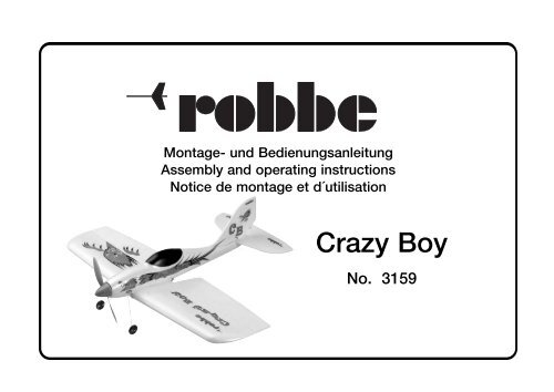
Robbe CRAZYBOY.pdf - RCtube.eu
Robbe CRAZYBOY.pdf - RCtube.eu
Robbe CRAZYBOY.pdf - RCtube.eu

Create successful ePaper yourself
Turn your PDF publications into a flip-book with our unique Google optimized e-Paper software.
Montage- und Bedienungsanleitung<br />
Assembly and operating instructions<br />
Notice de montage et d´utilisation<br />
Crazy Boy<br />
No. 3159
Technische Daten<br />
Spannweite: ca. 835 mm<br />
Länge: ca. 805 mm<br />
Gesamtflächeninhalt: ca. 24 dm 2<br />
Fluggewicht: ca. 400 g<br />
Gesamtflächenbelastung: ca. 16 g/dm 2<br />
Nicht enthaltenes Zubehör siehe Beilageblatt<br />
Werkz<strong>eu</strong>ge und Hilfsmittel siehe robbe Hauptkatalog<br />
Allgemeine Hinweise für den Bauablauf<br />
Die Numerierung entspricht im wesentlichen der Reihenfolge<br />
des Bauablaufs.<br />
Verschaffen Sie sich in Verbindung mit den Abbildungen und<br />
Kurztexten einen Überblick über die jeweiligen Bauschritte.<br />
Das Auffinden der Stanzteile erleichtern die<br />
Identifikationszeichnungen auf Seite 5.<br />
Verklebungen von Depron®<br />
Klebearbeiten an Depron® Teilen nur mit Foam Speed ausführen.<br />
Kleber auf Nitro- und Polyesterbasis und normaler<br />
Sekundenkleber führen zur Zerstörung des Werkstoffs.<br />
Richtungsangaben wie z. Bsp. „rechts“ sind in<br />
Flugrichtung zu sehen.<br />
Hinweise zur Fernst<strong>eu</strong>eranlage<br />
Als Fernst<strong>eu</strong>erung benötigen Sie eine Anlage ab 4 Kanälen<br />
und 4 Servos sowie einen elektronischen Flugregler.<br />
Orientieren Sie sich vor Baubeginn über die<br />
Einbaumöglichkeit der zu verwendenden Fernst<strong>eu</strong>erung.<br />
Sollte eine andere, als die von uns vorgeschlagene<br />
St<strong>eu</strong>erung verwendet werden, können Sie sich nach dem<br />
Einbauschema richten.<br />
Bauanleitung, Assembly instructions, Notice de montage<br />
Specification<br />
Crazy Boy<br />
Wingspan: approx. 835 mm<br />
Length: approx. 805 mm<br />
Total surface area: approx. 24 dm 2<br />
All-up weight: approx. 400 g<br />
Total surface area loading: approx. 16 g / dm 2<br />
See separate sheet for accessories not included in the kit.<br />
See the main robbe catalogue for details of tools and aids<br />
to building.<br />
Sequence of assembly<br />
In general terms the numbering of the kit components<br />
reflects the sequence of assembly.<br />
To gain a clear idea how the model goes together please<br />
study the illustrations and brief instructions.<br />
You will find identification drawings on page 5 which will<br />
help you locate the die-cut parts.<br />
Gluing Depron® components<br />
Use only robbe Foam-Speed (foam-safe cyano) to glue the<br />
Depron® components.<br />
Using ordinary cyano-acrylate, or any adhesive based on<br />
cellulose or polyester, will instantly ruin the material.<br />
Directions such as “right-hand” are as seen from the tail<br />
of the model looking forward.<br />
The radio control system<br />
To control the model you will need a radio control system<br />
with at least four channels, four servos and an electronic<br />
speed controller.<br />
Before you start construction check that your RC system<br />
components will fit in the suggested locations.<br />
If you wish to use a radio control system other than the one<br />
we recommend you can still base your installation on the<br />
arrangement shown.<br />
2<br />
Caractéristiques techniques<br />
No.<br />
3159<br />
envergure : approx. 835 mm<br />
longu<strong>eu</strong>r : approx. 805 mm<br />
surface alaire totale : approx. 24 dm 2<br />
poids en ordre de vol: approx. 400 g<br />
charge alaire à la surface totale : approx. 16 g/dm 2<br />
Accessoires non contenus dans la boîte de construction,<br />
cf. f<strong>eu</strong>illet joint.<br />
Outillage et accessoires de montage, cf. catalogue général<br />
robe.<br />
Recommandations générales concernant les séquences<br />
de construction.<br />
La numérotation correspond en règle générale à l’ordre d’intervention<br />
dans la construction.<br />
A l’aide des illustrations et des textes les accompagnant permettent<br />
de se familiariser avec les diverses étapes de la construction.<br />
L’identification des pièces estampées est facilitée par les<br />
schémas d’identification de la page 5.<br />
Collage des pièces en Depron®<br />
N’effectuer les travaux de collage sur les pièces en Depron®<br />
qu’avec le produit Foam Speed.<br />
Les colles à base de nitrométhane ou de polyester et les<br />
colles cyanoacrylates normales provoquent la destruction du<br />
matériau.<br />
Les indications directionnelles telles que droite ou gauche,<br />
par exemple, sont à considérer dans le sens du vol.<br />
Recommandations concernant l’ensemble de radiocommande<br />
L’ensemble de radiocommande approprié est un ensemble<br />
de radiocommande à partir de quatre voies et de quatre servos<br />
accompagnés d’un variat<strong>eu</strong>r électronique pour le mot<strong>eu</strong>r<br />
de l’hélice.
Maßdifferenzen sind von Ihnen selbst auszugleichen.<br />
Die angegebenen Ruderausschläge stellen einen Mittelwert<br />
dar. Je nach St<strong>eu</strong>ergewohnheiten und Motorisierung sind<br />
diese entsprechend zu verkleinern oder zu vergrößern.<br />
Hinweise zu den Querruderservos<br />
Die Querruderservos können mit einem V-Kabel an einem<br />
Empfängerkanal oder mit 2 Verlängerungskabeln an 2<br />
getrennten Kanälen angeschlossen werden.<br />
Bei Anschluß mit Verlängerungskabeln und einer<br />
entsprechenden Computer-Fernst<strong>eu</strong>erung können die<br />
Querruder als Klappen zum Höhenruder zugemischt werden,<br />
was die Wendigkeit des Modells erhöht.<br />
Hinweise zur Motorisierung<br />
In den Crazy-Boy kann wahlweise ein Brushlessmotor<br />
(Außenläufer) für Direktantrieb oder ein Bürstenmotor bzw.<br />
Brushless-Innenläufer mit Getriebe eingebaut werden.<br />
Beide Varianten sind in den Bildern 2 und 3 bzw. 4 bis 6<br />
dargestellt. Die erforderlichen, verschiedenen Motorspanten<br />
(2BR, 3BR für Direktantrieb, 4B, 5B für Getriebe-Antrieb)<br />
sind beigefügt.<br />
Vor Baubeginn den Motor mit entsprechendem Regler<br />
auswählen.<br />
Baukasteninhalt<br />
Nr. Bezeichnung Stück<br />
1 Rumpf 1<br />
2BR Motorspant 1<br />
3BR Aufdopplung 1<br />
-- Gewindeschraube M3 2-4<br />
4B Motorspant 1<br />
5B Aufdopplung 1<br />
-- Blechschraube Ø 2,2 x 9,5 mm 2<br />
Bauanleitung, Assembly instructions, Notice de montage<br />
Crazy Boy<br />
However, you may have to make allowance for minor differences<br />
in component sizes.<br />
The stated control surface travels represent average values.<br />
You may wish to reduce or increase them to suit the power<br />
system and your personal piloting preferences.<br />
Controlling the aileron servos<br />
The aileron servos can be connected to a single receiver<br />
channel using a Y-lead, or to two separate channels using<br />
a pair of extension leads.<br />
If you prefer the second option, and you have a computer<br />
radio control system with suitable facilities, you can configure<br />
the ailerons to work as flaps in opposition to the elevators,<br />
which further increases the model’s mano<strong>eu</strong>vrability.<br />
The power system<br />
The Crazy Boy can be fitted either with a direct-drive external<br />
rotor (out-runner) brushless motor, or a geared motor,<br />
either of the brushed or conventional brushless type.<br />
Both versions are shown in Figs. 2 and 3, and 4 to 6. The<br />
different motor bulkheads (2BR, 3BR for direct-drive<br />
motors, 4B, 5B for geared motors) are included in the kit.<br />
It is important to select the motor and matching speed controller<br />
before you start building the model.<br />
Kit contents<br />
No. Description No. off<br />
1 Fuselage 1<br />
2BR Motor bulkhead 1<br />
3BR Doubler 1<br />
-- M3 screw 2-4<br />
4B Motor bulkhead 1<br />
5B Doubler 1<br />
-- Self-tapping screw, 2.2 Ø x 9.5 mm 2<br />
3<br />
No.<br />
3159<br />
Avant d’entreprendre le montage vérifier les conditions<br />
d’implantation de l’ensemble de radiocommande que vous<br />
souhaitez installer.<br />
Si vous utilisez un ensemble de radiocommande autre que<br />
celui que nous recommandons, ajustez les cotes d’intégration<br />
des éléments utilisés en fonction des indications du<br />
schéma d‚implantation<br />
Compenser les différences de cote existantes.<br />
Le débattement des gouvernes indiqué constitue une<br />
val<strong>eu</strong>r moyenne qu’il faut augmenter ou réduire en fonction<br />
des habitudes de pilotage du pilote ou de l motorisation<br />
mise en place.<br />
Recommandations concernant les servos d’aileron<br />
Il est possible de raccorder les servos d’aileron à l’aide d’un<br />
cordon Y relié à une sortie u récept<strong>eu</strong>r ou à l’aide de d<strong>eu</strong>x<br />
cordons Y branchés sur d<strong>eu</strong>x sorties différentes du récept<strong>eu</strong>r.<br />
Avec un raccordement à l’aide de cordons rallonge sur un<br />
ensemble de radiocommande informatique il est possible<br />
d’utiliser les ailerons comme volets d‘atterrissage en les<br />
mixant avec la profond<strong>eu</strong>r pour augmenter la maniabilité du<br />
modèle.<br />
Recommandations concernant la motorisation<br />
Dans le modèle Crazy-Boy il est possible d’installer au<br />
choix un mot<strong>eu</strong>r sans balais (rotor extéri<strong>eu</strong>r) avec un<br />
entraînement direct ou un mot<strong>eu</strong>r à balais ou un mot<strong>eu</strong>r<br />
sans balais à rotor intéri<strong>eu</strong>r avec un engrenage.<br />
Les d<strong>eu</strong>x variantes sont présentées sur les fig. 2 et 3 ou 4<br />
à 6. Les couples mot<strong>eu</strong>rs différents nécessaires ((2BR, 3BR<br />
pour l‘entraînement direct, 4B, 5B pour l‘entraînement à<br />
engrenage) sont joints.<br />
Avant d‘installer le mot<strong>eu</strong>r, sélectionner le variat<strong>eu</strong>r approprié.
6 Keil 1<br />
7 Hauptspant vorn 1<br />
8 Halbspant 2<br />
9 Längsleiste, 0,5 x 10 x 150 2<br />
10 Hauptspant hinten 1<br />
11 RC-Platte 1<br />
12 Höhenruder 1<br />
13 Höhenleitwerk 1<br />
14 Seitenruder 1<br />
15 Seitenleitwerk 1<br />
16 Ruderhorn 2<br />
17 Seitenrudergestänge 1<br />
18 Höhenrudergestänge 1<br />
19 Kunststoffrohr 4<br />
20 Hauptfahrwerk 1<br />
21 Rad, zweiteilig 2<br />
22 Sicherungsscheibe 4<br />
23 Stützspant 1<br />
24 Hecksporn 1<br />
25 Querruder 2<br />
26 Tragfläche 1<br />
27 Servorahmen 2<br />
28 Randverstärkung 1<br />
29 Ruderhorn 2<br />
30 Querrudergestänge 2<br />
31 Kunstoffrohr 4<br />
32 Tragflächendübel 2<br />
33 Gummiring 2-4<br />
34 Spinner 1<br />
35 Spinner-Rückwand 1<br />
36 Rückwandboden 1<br />
37 Klötzchen 4<br />
38 Blechschraube, Ø 2,2 x 6,5 mm 4<br />
Bauanleitung, Assembly instructions, Notice de montage<br />
Crazy Boy<br />
6 Wedge 1<br />
7 Front main former 1<br />
8 Half-former 2<br />
9 Stringer, 0.5 x 10 x 150 2<br />
10 Rear main former 1<br />
11 RC plate 1<br />
12 Elevator 1<br />
13 Tailplane 1<br />
14 Rudder 1<br />
15 Fin 1<br />
16 Control surface horn 2<br />
17 Rudder pushrod 1<br />
18 Elevator pushrod 1<br />
19 Plastic sleeve 4<br />
20 Main undercarriage unit 1<br />
21 Two-part wheel 2<br />
22 Wheel retainer 4<br />
23 Tailskid support 1<br />
24 Tailskid 1<br />
25 Aileron 2<br />
26 Wing 1<br />
27 Servo frame 2<br />
28 Wing trailing edge doubler 1<br />
29 Aileron horn 2<br />
30 Aileron pushrod 2<br />
31 Plastic sleeve 4<br />
32 Wing dowel 2<br />
33 Rubber band 2 - 4<br />
34 Spinner 1<br />
35 Spinner backplate 1<br />
36 Spinner backplate base 1<br />
37 Spinner screw-block 4<br />
38 Self-tapping screw, 2.2 Ø x 6.5 mm 4<br />
4<br />
Contenu de la boîte de construction<br />
No.<br />
3159<br />
n° désignation nombre de pièces<br />
1 fuselage 1<br />
2BR couple-mot<strong>eu</strong>r 1<br />
3BR doublure 1<br />
-- tige filetée M3 2-4<br />
4B couple-mot<strong>eu</strong>r 1<br />
5B doublure 1<br />
-- vis autotaraud<strong>eu</strong>se Ø 2,2 x 9,5 mm 2<br />
6 coin 1<br />
7 demi-couple avant 1<br />
8 demi-couple 2<br />
9 longeron, 0,5 x 10 x 150 2<br />
10 demi-couple arrière 1<br />
11 platine de radiocommande 1<br />
12 gouverne de profond<strong>eu</strong>r 1<br />
13 stabilisat<strong>eu</strong>r 1<br />
14 gouverne de direction 1<br />
15 dérive 1<br />
16 guignol 2<br />
17 tringle de gouverne de direction 1<br />
18 tringle de gouverne de profond<strong>eu</strong>r 1<br />
19 tube en plastique 4<br />
20 atterriss<strong>eu</strong>r principal 1<br />
21 roue en d<strong>eu</strong>x parties 2<br />
22 circlips 4<br />
23 couple d'étai 1<br />
24 éperon de qu<strong>eu</strong>e 1<br />
25 aileron 2<br />
26 aile 1<br />
27 encadrement de servo 2<br />
28 renfort de bordure 1<br />
29 guignol 2<br />
30 tringle d'aileron 2<br />
31 tube en plastique 4<br />
32 cheville d'aile 2<br />
33 élastique 2-4<br />
34 cône d’hélice 1<br />
35 paroi arrière du cône d’hélice 1<br />
36 fond de paroi arrière 1<br />
37 cale 4<br />
38 vis autotaraud<strong>eu</strong>se, Ø 2,2 x 6,5 mm 4
25<br />
13<br />
11<br />
12<br />
1<br />
15<br />
10<br />
7<br />
26<br />
8 8<br />
25<br />
6<br />
14<br />
Bauanleitung, Assembly instructions, Notice de montage<br />
36<br />
28<br />
29<br />
16<br />
16<br />
27<br />
5B<br />
3BR<br />
2BR<br />
4B<br />
29<br />
23<br />
Crazy Boy<br />
5<br />
35<br />
17, 18<br />
21<br />
38, Ø 2,2 x 6,5<br />
24<br />
34<br />
37<br />
30<br />
9<br />
20<br />
33<br />
22<br />
19, 31<br />
No.<br />
3159<br />
32
Bauanleitung, Assembly instructions, Notice de montage<br />
Crazy Boy<br />
1 2<br />
3 4<br />
M 3<br />
Senkkopfschraube<br />
Countersunk screw<br />
Vis à tête fraisée<br />
Regler<br />
Speed controller<br />
Variat<strong>eu</strong>r de vitesse<br />
1<br />
“S”<br />
6<br />
8 mm<br />
3-5 mm<br />
2BR, 3BR<br />
4B, 5B<br />
2BR<br />
4B<br />
No.<br />
3159<br />
3BR<br />
5B
Bild 1<br />
- Bild 1 zeigt den Rumpf von unten mit dem<br />
Tragflächenausschnitt.<br />
Bild 2<br />
Einbau eines Brushless Motors<br />
- Den Motorspant 2BR so mit der Aufdopplung 3BR<br />
verkleben, dass die Bohrungen deckungsgleich aufeinander<br />
liegen.<br />
- Vorgesehenen Motor probeweise einsetzen und Lochbild<br />
von Motor und Spant vergleichen. Falls erforderlich<br />
nacharbeiten.<br />
- Motorspant einsetzen, rundum mit einem Rand von 3-5<br />
mm (je nach vorgesehenem Luftschraubenmitnehmer) zum<br />
Rumpfkopf ausrichten und verkleben.<br />
Bild 3<br />
- Bei den folgenden Arbeiten die Anleitungen beachten, die<br />
dem Motor bzw. dem Regler beigefügt sind.<br />
- Motorkabel des Reglers mit Schrumpfschlauchstücken<br />
versehen.<br />
- Die Anschlüsse von Motor und Regler miteinander verlöten.<br />
Lötstellen mit Schrumpfschlauch isolieren.<br />
- Am Akkukabel des Reglers eine zum vorgesehenen Akku<br />
passende Steckverbindung “S” anbringen.<br />
- Bei der Auswahl der Gewindeschrauben M 3 für den Motor<br />
die Einschraubtiefe im Motorgehäuse beachten.<br />
- Motor einsetzen und mit 2-4 Schrauben befestigen.<br />
Bild 4<br />
Einbau eines Bürstenmotors<br />
- Motorspant 4B und Aufdopplung 5B deckungsgleich<br />
aufeinanderkleben.<br />
- Motorspant einsetzen, rundum mit einem Rand von 8 mm<br />
zum Rumpfkopf ausrichten und verkleben. Der Ausschnitt<br />
für den Motor muss sich unten befinden.<br />
Bauanleitung, Assembly instructions, Notice de montage<br />
Fig. 1<br />
Crazy Boy<br />
- Fig. 1 shows the underside of the fuselage and the wing<br />
saddle.<br />
Fig. 2<br />
Installing a brushless motor<br />
- Glue the motor bulkhead 2BR to the doubler 3BR; take<br />
care to line up the holes accurately.<br />
- Offer up the motor to the bulkhead assembly and check<br />
the hole pattern; carry out any adjustments required.<br />
- Place the bulkhead assembly in the fuselage and position<br />
it inset by 3-5 mm all round (according to the propeller<br />
coupling you want to use). Glue the parts together.<br />
Fig. 3<br />
- Before carrying out the next stage please read the instructions<br />
supplied with the motor and the speed controller.<br />
- Locate the motor cables attached to the speed controller<br />
and fit small pieces of heat-shrink sleeve on them.<br />
- Solder the motor and controller cables together, and insulate<br />
each soldered joint with a heat-shrink sleeve.<br />
- Locate the battery leads attached to the speed controller,<br />
and fit the appropriate connector “S” (matching the flight<br />
battery you intend to use) to them.<br />
- Select the M3 retaining screws for the motor, and check<br />
carefully that they are the correct length - they must not<br />
intrude too far into the motor case.<br />
- Fit the motor and secure it using the 2-4 screws.<br />
Fig. 4<br />
Installing a brushed motor<br />
- Glue the motor bulkhead 4B to the doubler 5B with the<br />
edges flush all round.<br />
- Place the bulkhead assembly in the fuselage and position<br />
it inset by 8 mm all round. Note that the opening for the<br />
motor must be at the bottom. Glue the parts together.<br />
7<br />
fig. 1<br />
- La fig. 1 présente le fuselage vu du dessous avec la<br />
découpe destinée à l’aile.<br />
fig. 2<br />
Mise en place d’un mot<strong>eu</strong>r sans balais<br />
- Coller le couple-mot<strong>eu</strong>r 2BR avec la doublure 3BR de telle<br />
sorte que les alésages coïncident parfaitement.<br />
- Mettre le mot<strong>eu</strong>r prévu provisoirement en place et comparer<br />
à titre d’essai les alésages de fixation du mot<strong>eu</strong>r<br />
avec c<strong>eu</strong>x du couple. Effectuer les corrections qui s’imposent,<br />
si nécessaire.<br />
- Mettre le couple-mot<strong>eu</strong>r en place, l’aligner avec une marge<br />
de 3 à 5 mm (selon moy<strong>eu</strong> d’hélice) par rapport au nez du<br />
fuselage et le coller.<br />
fig. 3<br />
- Pour les travaux suivants, tenir compte des indications<br />
fournies par la notice accompagnant le mot<strong>eu</strong>r et le variat<strong>eu</strong>r.<br />
- Isoler le cordon du mot<strong>eu</strong>r sur le variat<strong>eu</strong>r à l’aide de<br />
morceau de gaine thermorétractable.<br />
- Souder l’un à l’autre les raccords du mot<strong>eu</strong>r et du variat<strong>eu</strong>r.<br />
Isoler les points de soudure avec des morceaux de<br />
gaine thermorétractable.<br />
- Sur le cordon de l’accu du variat<strong>eu</strong>r installer un connect<strong>eu</strong>r<br />
“S” approprié à l’accu prévu.<br />
- Lors du choix des vis M 3de fixation du mot<strong>eu</strong>r, tenir<br />
compte de la profond<strong>eu</strong>r de vissage dans le carter du<br />
mot<strong>eu</strong>r.<br />
- Mettre le mot<strong>eu</strong>r en place et le fixer avec 2-4 vis.<br />
fig. 4<br />
No.<br />
3159<br />
Mise en place d’un mot<strong>eu</strong>r à balais<br />
- Coller l’un sur l’autre le couple-mot<strong>eu</strong>r 4B et la doublure<br />
5B de manière qu’ils coïncident parfaitement.<br />
- Mettre le couple-mot<strong>eu</strong>r en place et l’ajuste avec une<br />
marge de 8 mm tout autour par rapport au nez du fuselage.<br />
Le dégagement pour le mot<strong>eu</strong>r doit se trouver en bas.
Bauanleitung, Assembly instructions, Notice de montage<br />
Crazy Boy<br />
5<br />
Regler<br />
Speed controller<br />
6<br />
100 nF 100 nF<br />
Variat<strong>eu</strong>r de vitesse<br />
47 nF<br />
F<br />
7 8<br />
7, 8<br />
“U”<br />
8<br />
8<br />
7<br />
“S”<br />
8<br />
10<br />
Ø 2,2 x 9,5 mm<br />
9<br />
No.<br />
3159<br />
9
Bild 5<br />
- Den Bürsten-Motor entstören. Dazu die Kondensatoren<br />
100 nF jeweils mit einem Beinchen an das Gehäuse löten,<br />
welches dazu blankzufeilen ist. Zweites Beinchen mit<br />
Isolierschlauch an die Motorpole stecken. Die Beinchen<br />
des Kondensators 47 nF mit Isolierschlauch versehen<br />
und ebenfalls an die Motorpole stecken.<br />
- Ferritkern "F" 1x durch das Motoranschlußkabel des<br />
Reglers schlingen. Das Kabel an die Motorpole löten, die<br />
Kondensatoren werden dabei mitverlötet.<br />
- Das Stecksystem anbringen. Auf richtige Polarität achten.<br />
Regleranleitung beachten.<br />
- Motorwelle mit Schleifpapier in Längsrichtung aufrauhen.<br />
- Etwas Loctite in die Bohrung des Ritzels träufeln. Das<br />
Ritzel hochkant auf den Arbeitstisch legen und<br />
Motorwelle einpressen. Dabei von hinten auf die<br />
Motorwelle drücken. Die Welle muß vorn bündig mit dem<br />
Ritzel abschließen.<br />
- Innenzahnrad und Getriebewelle gut einfetten.<br />
- Die Scheibe “U” als Zwischenlage einlegen und das<br />
Getriebegehäuse auf den Motor stecken.<br />
Bild 6<br />
- Antrieb von vorn einschieben. Löcher bohren, Antrieb mit<br />
Blechschrauben Ø 2,2 x 9,5 mm befestigen.<br />
Anschlußkabel nach hinten in den Rumpf führen.<br />
Bild 7<br />
- Den Keil 6 vom vorderen Hauptspant 7 abtrennen.<br />
- Die Halbspanten 8 beidseitig auf den Spant 7 aufkleben.<br />
- Die Öffnung für das Hauptfahrwerk nach Markierung<br />
ausschneiden.<br />
- Spant 7 in den Rumpf setzen, ausrichten und verkleben.<br />
Dabei die Öffnung für das Hauptfahrwerk beachten.<br />
Bild 8<br />
- Längsleisten 9 und hinteren Hauptspant 10 gemeinsam<br />
einsetzen und ausrichten. Nur die Längsleisten im<br />
Rumpf verkleben.<br />
Bauanleitung, Assembly instructions, Notice de montage<br />
Crazy Boy<br />
Fig. 5<br />
- The next stage is to fit the suppressor capacitors to the<br />
brushed motor. Solder one pin of one 100 nF capacitor to the<br />
motor can. Fit an insulating sleeve on the other pin, and<br />
thread it through one motor terminal; file the motor can perfectly<br />
clean before soldering. Repeat the procedure with the<br />
second 100 nF capacitor and the other motor terminal. Fit<br />
insulating sleeves on both pins of the 47 nF capacitor, and<br />
solder it across the motor terminals as a bridge.<br />
- Wind the motor cables attached to the speed controller<br />
through the ferrite ring “F” for one complete turn as shown.<br />
Solder the wires to the motor terminals, soldering the capacitors<br />
in place at the same time.<br />
- Attach the connectors, taking great care to maintain correct<br />
polarity. Read the speed controller instructions if you are not<br />
sure of this.<br />
- Rub the motor shaft in the axial direction with abrasive paper.<br />
- Apply a little Loctite to the inside of the pinion bore. Place the<br />
pinion flat on the workbench, hole uppermost, and press the<br />
motor shaft into it, pressing on the other end of the shaft; the<br />
shaft should end flush with the pinion.<br />
- Thoroughly grease the internal-tooth gear and the gearbox<br />
shaft.<br />
- Position the spacer disc “U” as shown, and fit the gearbox<br />
housing on the motor.<br />
Fig. 6<br />
- Fit the motor assembly into the nose bulkhead from the front;<br />
mark and drill the holes for the retaining screws. Attach the<br />
motor using the 2.2 Ø x 9.5 mm self-tapping screws supplied,<br />
and run the motor leads back into the fuselage.<br />
Fig. 7<br />
- Cut the wedge 6 from the underside of the front main former<br />
7 to create a recess for the main undercarriage.<br />
- Glue the half-formers 8 on both sides of the former 7.<br />
- Cut out the slot in the underside of the fuselage for the main<br />
undercarriage unit, as shown in the drawing.<br />
- Place the former 7 in the fuselage, align it carefully and glue<br />
it in place. Make sure that the slot for the main undercarriage<br />
unit lines up correctly with the recess in the former.<br />
Fig. 8<br />
- Fit the stringers 9 and the rear main former 10 at the same<br />
time, and align them carefully. Glue the stringers to the<br />
fuselage, but don’t glue the former at this stage.<br />
9<br />
No.<br />
3159<br />
fig. 5<br />
- Antiparasiter le mot<strong>eu</strong>r à balais. Pour ce faire, souder systématiquement<br />
une broche des condensat<strong>eu</strong>rs 100 nF au<br />
carter du mot<strong>eu</strong>r qui aura préalablement été limé. Souder<br />
la seconde broche des condensat<strong>eu</strong>rs après les avoir<br />
isolées avec des morceaux de gaine thermorétractable<br />
aux pôles du mot<strong>eu</strong>r.<br />
- Disposer le noyau de ferrite "F" 1x au travers du cordon de<br />
connexion du mot<strong>eu</strong>r sur le variat<strong>eu</strong>r. Souder le cordon aux<br />
pôles du mot<strong>eu</strong>r en soudant simultanément les broches de<br />
condensat<strong>eu</strong>r.<br />
- Mettre le système de connexion en place. Observer la<br />
polarité des brins.<br />
Observer les instructions fournies par la notice accompagnant<br />
le variat<strong>eu</strong>r.<br />
- Poncer l’arbre du mot<strong>eu</strong>r longitudinalement avec du papier<br />
de verre.<br />
- Verser une goutte de Loctite dabs l’alésage du pignon.<br />
Installer le pignon debout sur un chantier plan et engager<br />
l’arbre du mot<strong>eu</strong>r en appliquant une forte pression. L’arbre<br />
doit se trouver à fl<strong>eu</strong>r à l’avant avec le pignon.<br />
- Bien graisser la roue dentée intéri<strong>eu</strong>re et l’arbre d’engrenage.<br />
- Intercaler la rondelle”U” et planter le carter d’engrenage<br />
sur le mot<strong>eu</strong>r.<br />
fig. 6<br />
- Engager l’entraînement par l’avant. Percer les trous, fixer<br />
l’entraînement à l’aide des vis autotaraud<strong>eu</strong>ses Ø 2,2 x 9,5<br />
mm.<br />
Amener le cordon de connexion vers l’arrière dans le fuselage.<br />
fig. 7<br />
- Désolidariser le coin 6 du couple principal avant 7.<br />
- Coller e demi-couple 8 de chaque côté sur le couple 7.<br />
- Découper le dégagement de l’atterriss<strong>eu</strong>r principal en<br />
fonction des repères.<br />
- Installer le couple 7 dans le fuselage, l’aligner et le coller.<br />
Ce faisant, tenir compte du dégagement destiné à l’atterriss<strong>eu</strong>r<br />
principal.<br />
fig. 8<br />
- Mettre les longerons 9 et le couple principal arrière 10 en<br />
place simultanément et les aligner. Ne coller que les<br />
longerons dans le fuselage.
Bauanleitung, Assembly instructions, Notice de montage<br />
Crazy Boy<br />
9 10<br />
11 12<br />
Ø 1 mm Ø 1 mm<br />
16<br />
7<br />
11<br />
10<br />
9<br />
11<br />
16<br />
10<br />
10<br />
12<br />
12<br />
„R“<br />
„R“<br />
„SP“<br />
90°<br />
„D“<br />
15<br />
13<br />
13<br />
15<br />
„D“<br />
„SP“<br />
3 mm<br />
„R“<br />
No.<br />
3159<br />
14<br />
14<br />
14, 15, 16<br />
12, 13, 16
Bild 9<br />
- RC-Platte 11 so in den Rumpf setzen, dass sie in den<br />
Aussparungen der Spanten 7 und 10 liegt. Spant 10 dazu<br />
entsprechend verschieben. Alle Teile zueinander ausrichten<br />
und verkleben.<br />
Bild 10<br />
- Höhen- und Seitenruder 12, 14 von den Leitwerken 13 und<br />
15 abtrennen. Spalte „SP“ anschleifen. Über die Kante<br />
des Höhenleitwerks einen Streifen Klebeband als<br />
Ruderscharnier „R“ kleben. Ruder umklappen und auf der<br />
Unterseite einen zweiten Streifen Klebeband anbringen.<br />
- Beim Seitenruder/Seitenleitwerk Klebeband beidseitig<br />
anbringen. Die Ruder mehrfach hin- und herbewegen, um<br />
die Leichtgängigkeit zu gewährleisten.<br />
Bild 11<br />
- Gemäß Markierungen Schlitze für die Ruderhörner 16 in<br />
den Rudern einschneiden.<br />
- Ruderhörner 16 mit 1 mm bohren und in die Schlitze der<br />
Ruder 12 und 14 einkleben.<br />
Bild 12<br />
- Schlitz für das Seitenleitwerk im Rumpfende nach<br />
Markierungen austrennen. Ebenso die Durchbrüche “D”<br />
für die Gestänge beidseitig ausarbeiten.<br />
- Den Rumpf auf die Tragfläche setzen. Höhenleitwerk parallel<br />
fluchtend zur Tragfläche und mittig auf das<br />
Rumpfende kleben.<br />
- Seitenleitwerk rechtwinklig zum Höhenleitwerk aufkleben.<br />
3 mm Abstand zum Höhenleitwerk einhalten.<br />
Bauanleitung, Assembly instructions, Notice de montage<br />
Fig. 9<br />
Crazy Boy<br />
- Place the RC plate 11 in the fuselage, and engage the lugs<br />
in the notches of the formers 7 and 10, adjusting the position<br />
of the former 10 accordingly. Check that everything fits<br />
as shown, then glue the parts together and to the fuselage.<br />
Fig. 10<br />
- Separate the elevator 12 from the tailplane 13, and the rudder<br />
14 from the fin 15. Sand the hinge lines “SP” to the<br />
sections shown. Apply a strip of adhesive tape on the top<br />
surface of the trailing edge of the tailplane and the leading<br />
edge of the elevator to act as the elevator hinge “R”. Fold<br />
the elevator “up and over”, and apply a second strip of<br />
tape on the underside.<br />
- Apply the hinge tape on both sides of the fin and rudder as<br />
shown. Move the control surfaces repeatedly to and fro to<br />
satisfy yourself that they move smoothly and freely.<br />
Fig. 11<br />
- Cut slots at the marked points in the control surfaces to<br />
accept the horns 16.<br />
- Drill 1 mm Ø holes in the horns for the pushrods, and glue<br />
them in the slots in the elevator 12 and rudder 14.<br />
Fig. 12<br />
- Cut the slot in the tail end of the fuselage to accept the fin,<br />
working along the marked lines. At the same time cut the<br />
slots “D” for the pushrods on both sides of the fuselage.<br />
- Place the fuselage on the wing. Set the tailplane parallel to<br />
the wing as seen from the nose, and glue it to the tail end<br />
of the fuselage. Check that the tailplane is exactly central<br />
when viewed from above.<br />
- Glue the fin on the tailplane, setting it exactly at rightangles.<br />
Note that the rudder must have 3 mm clearance<br />
above the tailplane.<br />
11<br />
fig. 9<br />
No.<br />
3159<br />
- Installer la platine de radiocommande 11 dans le fuselage<br />
de telle sorte qu’elle s’engage dans les dégagements des<br />
couples 7 et 10. Déplacer le couple 10 en conséquence.<br />
Aligner tous les éléments les uns par rapport aux autres et<br />
les coller.<br />
fig. 10<br />
- Détacher la gouverne de profond<strong>eu</strong>r et la gouverne de<br />
direction 12, 14 des plans fixes 13 et 15. Poncer le joint<br />
“SP”. Coller une bande de ruban adhésif sur l’arête du stabilisat<strong>eu</strong>r,<br />
elle fera office de charnière “R” de gouverne.<br />
Rabattre la gouverne et sur son intrados, appliquer un second<br />
morceau de ruban adhésif.<br />
- Appliquer des morceaux de ruban adhésif de chaque côté<br />
sur l’ensemble gouverne de direction /dérive. Déplacer les<br />
gouvernes plusi<strong>eu</strong>rs fois dans les d<strong>eu</strong>x sens de débattement<br />
afin d’assurer l<strong>eu</strong>r souplesse.<br />
fig. 11<br />
- En fonction des repères, entailler les fentes des guignols<br />
16 dans les gouvernes.<br />
- Percer les guignols 16 avec une mèche de 1 mm et les<br />
coller dans les fentes des gouvernes 12 et 14.<br />
fig. 12<br />
- Détacher la fente de la dérive dans la qu<strong>eu</strong>e du fuselage en<br />
fonction des repères. Réaliser également de chaque côté<br />
les passages ”D” destinés aux tringles.<br />
- Installe le fuselage sur l’aile. Coller le stabilisat<strong>eu</strong>r et centre<br />
de la qu<strong>eu</strong>e du fuselage parfaitement parallèle à l’aile.<br />
- Coller le dérive perpendiculairement par rapport au stabilisat<strong>eu</strong>r.<br />
Observer l’écart de 3 mm par rapport au stabilisat<strong>eu</strong>r.
Bauanleitung, Assembly instructions, Notice de montage<br />
Crazy Boy<br />
13 14<br />
11<br />
15 16<br />
19<br />
16<br />
12<br />
19<br />
21<br />
90°<br />
90°<br />
17<br />
18<br />
17, 18<br />
18<br />
6<br />
17<br />
20<br />
22<br />
No.<br />
3159
Bild 13<br />
- Die Servohebel von den Servos abnehmen.<br />
- Servos in die RC-Platte 11 einsetzen und mit Foam Speed<br />
sichern. Kabel nach vorn führen.<br />
Bild 14<br />
- Seiten- und Höhenrudergestänge 17 und 18 in die Schlitze<br />
am Rumpfheck einschieben und in den Servohebeln einhängen.<br />
- Zur Sicherung ein kurzes Stück Kunststoffrohr 19 auf das<br />
Ende schieben und mit einem Tropfen Sekundenkleber<br />
sichern.<br />
- Servos mit der Fernst<strong>eu</strong>erung in N<strong>eu</strong>tralstellung bringen.<br />
- Hebel so aufstecken, dass sie mit den Gestängen jeweils<br />
einen Winkel von 90° bilden und mit den<br />
Servohebelschrauben sichern.<br />
Bild 15<br />
- Beide Ruder genau in Mittelstellung bringen und fixieren.<br />
Gestänge genau über der Bohrung des jeweiligen<br />
Ruderhorns markieren und abwinkeln.<br />
- Enden in den Ruderhörnern einhängen.<br />
- Leichtgängigen Lauf der Gestänge prüfen. Falls erforderlich,<br />
die Durchbrüche am Rumpfende nacharbeiten.<br />
- Gestängeenden an den Ruderhörnern mit Kunststoffrohr-<br />
Abschnitten sichern. Überstand abtrennen.<br />
- Je nach Servohöhe gegebenenfalls die Schlitze für die<br />
Führungsröhrchen im Hauptspant 10 ausfeilen.<br />
- Führungsröhrchen am Hauptspant 10 und am Rumpfende<br />
mit Klebstoff fixieren.<br />
Bild 16<br />
- Hauptfahrwerk 20 parallel zum Höhenleitwerk ausrichten<br />
und Keil 6 mit Foam Speed einkleben.<br />
- Die Halbschalen 21 für die Räder zusammenkleben.<br />
- Räder auf Ø 1,5 mm aufbohren.<br />
- Räder mit innen und außen auf das Hauptfahrwerk<br />
geschobenen Sicherungsclipsen 22 drehbar fixieren.<br />
Bauanleitung, Assembly instructions, Notice de montage<br />
Fig. 13<br />
Crazy Boy<br />
- Remove the output levers from the servos.<br />
- Place the servos in the openings in the RC plate 11, and<br />
secure each with two drops of Foam Speed. Run the servo<br />
leads forward as shown.<br />
Fig. 14<br />
- Slip the rudder pushrod 17 and the elevator pushrod 18<br />
through the slots in the tail end of the fuselage, and connect<br />
them to the servo output arms.<br />
- Push a short piece of plastic sleeve 19 onto the angled end<br />
of the pushrod, and secure it with a tiny drop of cyano.<br />
- Set the servos to n<strong>eu</strong>tral (centre) from the transmitter.<br />
- Fit the output arms on the servos in such a way that they<br />
form an angle of 90° to the pushrods. Secure the output<br />
arms with the output screws.<br />
Fig. 15<br />
- Set the rudder and elevator to centre and tape them in that<br />
position. Mark the exact point where the pushrods cross<br />
the holes in the control surface horns, then bend the end at<br />
90° at the marked point.<br />
- Connect the angled ends to the rudder and elevator horns.<br />
- Check that the linkages work smoothly and freely; adjust<br />
the slots in the tail end of the fuselage if necessary.<br />
- Secure the pushrod ends at the horns using short pieces of<br />
plastic sleeve, as described earlier, and cut off the excess<br />
pushrod length.<br />
- If necessary, file out the slots for the guide tubes in the main<br />
former 10 to match the level of the servo output arms.<br />
- Glue the guide tubes to the main former 10 and the slots in<br />
the tail end of the fuselage.<br />
Fig. 16<br />
- Insert the main undercarriage unit 10, and set the wheel<br />
axles parallel to the tailplane. Fit the wedge 6, and glue the<br />
parts together using Foam Speed.<br />
- Glue together the shells 21 to form the main wheels.<br />
- Drill out the completed wheels to 1.5 mm Ø.<br />
- Fit the wheels on the main undercarriage axles and secure<br />
them by pushing the wheel retainers 22 onto the wire.<br />
Check that the wheels rotate freely.<br />
13<br />
fig. 13<br />
No.<br />
3159<br />
- Retirer les palonniers des servos.<br />
- Installer les servos dans la platine de radiocommande 11<br />
et les fixer avec le produit Foam Speed. Amener les cordons<br />
vers l’avant.<br />
fig. 14<br />
- Glisser la tringle de direction et la tringle de gouverne de<br />
profond<strong>eu</strong>r 17 et 18 dans les fentes de la qu<strong>eu</strong>e du fuselage<br />
et les accrocher aux palonniers des servos.<br />
- Pour l<strong>eu</strong>r fixation, glisser un morceau court de tube en<br />
plastique 19 sur l’extrémité et l’y fixer avec une goutte de<br />
colle cyanoacrylate.<br />
- Amener les servos au n<strong>eu</strong>tre à l’aide de l’ensemble de<br />
radiocommande.<br />
- Mettre les palonniers de servo en place de telle sorte qu’ils<br />
constituent avec les tringles un angle de 90° et les fixer<br />
avec les vis des servos.<br />
fig. 15<br />
- Amener les d<strong>eu</strong>x gouvernes exactement en position médiane<br />
et les fixer.<br />
Appliquer un repère sur les tringles exactement au niveau<br />
de l’alésage du guignol approprié et les cintrer.<br />
- Accrocher les extrémités dans les guignols.<br />
- Contrôler la souplesse de déplacement des tringles et, si<br />
nécessaire, retravailler les passages de tringle à l’extrémité<br />
du fuselage.<br />
- Fixer les extrémités des tringles aux guignols avec des<br />
morceaux de tube en plastique. Détacher les saillies.<br />
- En fonction de la haut<strong>eu</strong>r des servos, si nécessaire, limer<br />
les fentes des tubes-guides dans le couple principal 10.<br />
- Fixer les tubes-guides au couple principal 10 et à la qu<strong>eu</strong>e<br />
du fuselage à l’aide de colle.<br />
fig. 16<br />
- Aligner l’atterriss<strong>eu</strong>r principal 20 parallèlement au stabilisat<strong>eu</strong>r<br />
et coller le coin 6 avec le produit Foam Speed.<br />
- Coller ensemble les demi-coquilles 21 des roues.<br />
- Porter les alésages de roues à Ø 1,5 mm avec une mèche<br />
appropriée.<br />
- Fixer les roues à l’intéri<strong>eu</strong>r et à l’extéri<strong>eu</strong>r sur l’ atterriss<strong>eu</strong>r<br />
principal à l’aide des circlips 22 mise en place en veillant à<br />
ce qu’elles tournent avec souplesse.
Bauanleitung, Assembly instructions, Notice de montage<br />
Crazy Boy<br />
17 18<br />
24<br />
19 20<br />
27<br />
27<br />
23<br />
14<br />
26<br />
25<br />
“R”<br />
“R”<br />
No.<br />
3159<br />
28
Bild 17<br />
- Den Stützspant 23 mit dem Hecksporn 24 verkleben.<br />
Schlitz im Rumpfheck einschneiden, Einheit einkleben.<br />
Bild 18<br />
- Die Querruder 25 einseitig über die ganze Länge gleichmäßig<br />
anschrägen.<br />
- Ruder an die Tragfläche 26 ansetzen und mit Tesastreifen<br />
als Ruderscharnier “R” von oben und unten über die ganze<br />
Länge befestigen.<br />
Bild 19<br />
- Die Servorahmen 27 auflegen und mit Tesastreifen fixieren,<br />
noch nicht verkleben.<br />
- Servo-Ausschnitte innen anzeichnen.<br />
Bild 20<br />
- Servoschächte für die Servos nach angezeichneten<br />
Markierungen austrennen.<br />
- Die Randverstärkung 28 auf die Tragflächenunterseite<br />
kleben.<br />
Bauanleitung, Assembly instructions, Notice de montage<br />
Fig. 17<br />
Crazy Boy<br />
- Glue the support 23 to the tailskid 24. Cut a slot for the<br />
skid assembly in the tail end of the fuselage, and glue the<br />
assembly in it.<br />
Fig. 18<br />
- Bevel the leading edge of the ailerons as shown in the<br />
cross-section. Take care to keep the hinge line straight,<br />
and the bevel angle constant.<br />
- Offer up one aileron to the wing 26, and apply a full-length<br />
tape hinge “R” using Tesa tape or similar to the top and<br />
bottom of the hinge axis.<br />
Fig. 19<br />
- Place the servo frames 27 on the wing and tape them in<br />
place; don’t glue them at this stage.<br />
- Mark the servo openings on the wing using the frames as<br />
a template.<br />
Fig. 20<br />
- Cut out the recesses for the servos, working along the<br />
marked lines.<br />
- Glue the trailing edge doubler 28 on the underside of the<br />
wing as shown.<br />
15<br />
fig. 17<br />
- Coller le couple d'étai 23 à l’ éperon de qu<strong>eu</strong>e 24.<br />
Entailler la fente dans la qu<strong>eu</strong>e et coller l’unité.<br />
fig. 18<br />
No.<br />
3159<br />
- Biaiser les ailerons 25 d’un côté sur toute la longu<strong>eu</strong>r de<br />
manière homogène.<br />
- Installer les ailerons sur l’aile 26 et les fixer avec des<br />
morceaux de ruban adhésif ”R”, faisant office de charnière<br />
sur l’intrados et sur l’extrados, sur toute l<strong>eu</strong>r longu<strong>eu</strong>r.<br />
fig. 19<br />
- Mettre l’encadrement de servo 27 en place et le fixer avec<br />
des morceaux de ruban adhésif, sans coller pour l’instant.<br />
- Marquer les dégagement des servos à l’intéri<strong>eu</strong>r.<br />
fig. 20<br />
- Détacher les logements de servo en fonction des repères<br />
appliqués.<br />
- Coller les renforts de bordure 28 sur l’intrados de l’aile.
Bauanleitung, Assembly instructions, Notice de montage<br />
Crazy Boy<br />
21 22<br />
23 24<br />
Ø 10 mm<br />
16<br />
30<br />
Ø 3 mm<br />
31<br />
29<br />
32<br />
31<br />
30<br />
Ø 1 mm<br />
Ø 3 mm<br />
29<br />
No.<br />
3159
Bild 21<br />
- Servohebel abnehmen, Servos mit der Fernst<strong>eu</strong>erung in<br />
N<strong>eu</strong>tralstellung bringen.<br />
- Servohebel bearbeiten und spiegelbildlich auf die Servos<br />
stecken.<br />
- Hebel mit Servohebelschrauben sichern.<br />
- Servos einsetzen.<br />
Bild 22<br />
- Ruderhörner 29 mit Ø 1 mm bohren.<br />
- Ruderhörner und Gestänge 30 einbauen, Gestängeenden<br />
mit Kunststoffröhrchen 31 sichern.<br />
- Servos mit Rahmen verschieben, bis sich die Querruder<br />
beide in Mittelstellung befinden. In dieser Position die<br />
Servorahmen auf der Tragfläche verkleben.<br />
- Servos mit Schrauben oder Foam Speed fixieren.<br />
Bild 23<br />
- Auf der Tragflächen-Oberseite ein Loch von ca. Ø 10 mm<br />
nach Markierung einschneiden und die Kabel der<br />
Querruderservos nach außen führen.<br />
Bild 24<br />
- Löcher Ø 3 mm nach Markierungen im Rumpf durchstechen.<br />
Dübel 32 einschieben, mittig ausrichten und<br />
verkleben.<br />
Bauanleitung, Assembly instructions, Notice de montage<br />
Fig. 21<br />
Crazy Boy<br />
- Remove the aileron servo output levers and set the servos<br />
to centre from the transmitter.<br />
- Cut down the servo output arms as shown, and fit them on<br />
the servos in a mirror-image arrangement (both arms facing<br />
the centre).<br />
- Secure the output arms using the servo output screws.<br />
- Place the aileron servos in the servo frames.<br />
Fig. 22<br />
- Drill 1 mm Ø holes in the aileron horns 29.<br />
- Install the horns and the pushrods 30, and secure the<br />
pushrod ends with short pieces of plastic sleeve 31.<br />
- Adjust the position of the servos and the servo frames until<br />
both ailerons are at n<strong>eu</strong>tral (centre). In this position glue the<br />
servo frames to the wing.<br />
- Check alignment once more, then fix the servos to the<br />
frames using screws or a little Foam Speed.<br />
Fig. 23<br />
- Cut a hole about 10 mm Ø at the marked position in the<br />
top of the wing. Thread the aileron servo cables through<br />
the hole and out of the wing.<br />
Fig. 24<br />
- Pierce 3 mm Ø holes at the marked points in the fuselage.<br />
Slide the wing dowels 32 through the holes, set them central,<br />
and glue them to the fuselage.<br />
17<br />
fig. 21<br />
No.<br />
3159<br />
- Retirer le palonnier du servo, amener le servo au n<strong>eu</strong>tre à<br />
l’aide de l’ensemble de radiocommande.<br />
- Travailler les palonniers de servo et installer les palonnier<br />
symétriquement sur les servos.<br />
- Fixer les palonniers à l’aide des vis de servo.<br />
- Mettre les servos en place.<br />
fig. 22<br />
- Percer les guignols 29 avec une mèche de Ø 1 mm.<br />
- Monter les guignols et la tringlerie 30, fixer les extrémités<br />
de tringle à laide de tubes en plastique 31.<br />
- Décaler les servos dans l<strong>eu</strong>r châssis jusqu’à ce que les<br />
d<strong>eu</strong>x ailerons se trouvent en position médiane. Dans cette<br />
position, coller les encadrements de servo sur l’aile.<br />
- Fixer les servos avec des vis ou du produit Foam Speed.<br />
fig. 23<br />
- Sur l’extrados de l’aile, entailler un trou d’approx. Ø 10 mm<br />
en fonction du repère et amener les cordons des servos<br />
d’aileron vers l’extéri<strong>eu</strong>r.<br />
fig. 24<br />
- Transpercer les trous de Ø 3 mm en fonction des repères<br />
dans le fuselage.<br />
Mettre les chevilles 32 en place, les aligner et les coller.
Bauanleitung, Assembly instructions, Notice de montage<br />
Crazy Boy<br />
25 33<br />
26<br />
27 28<br />
Ø 1,5 mm<br />
33<br />
34 - 37<br />
90°<br />
18<br />
4 x<br />
35<br />
34<br />
38, Ø 2,2 x 6,5<br />
35 - 37<br />
35<br />
36<br />
37<br />
No.<br />
3159<br />
10 mm<br />
1 mm<br />
37
Bild 25<br />
- Die Tragfläche probeweise aufsetzen und mit je 2 über<br />
Kr<strong>eu</strong>z gespannten Gummiringen 33 befestigen.<br />
Bild 26<br />
- Spinner 34 und Spinner-Rückwand 35 nach Markierungen<br />
austrennen. Bei der Rückwand muß ein umlaufender Rand<br />
von ca 1 mm stehen bleiben, auf welchem der Spinner<br />
später aufliegt.<br />
- Rückwandboden 36 in die Rückwand einpassen und einkleben.<br />
- Die Bohrung zur Befestigung des Spinners zunächst mit<br />
6mm zentrisch ausarbeiten.<br />
- Vier 10 mm Leistenstücke 37 zuschneiden und auf die<br />
Spinner-Rückwand kleben.<br />
Bild 27<br />
- Den Spinner auf die Rückwand setzen. Löcher Ø 1,5 mm<br />
durch Spinner und Leistenstücke bohren. Nur im Spinner<br />
die Löcher auf Ø 2 mm aufbohren.<br />
- Spinner ern<strong>eu</strong>t aufsetzen. Überstehenden Rand der<br />
Rückwand zum Spinner verschleifen.<br />
- Ausschnitte für die vorgesehene Luftschraube ausarbeiten.<br />
Bild 28<br />
Montage von Luftschraube und Spinner auf einem<br />
Direktantrieb<br />
- Geeignete Luftschraubenkupplung auswählen. Loch Ø 6<br />
mm in der Spinner-Rückwand entsprechend erweitern.<br />
- Bei der Montage der Teile auf ausreichenden Abstand der<br />
Spinner-Rückwand zum Rumpfkopf achten.<br />
- Spinner mit 4 Blechschrauben 38 befestigen.<br />
Bauanleitung, Assembly instructions, Notice de montage<br />
Fig. 25<br />
Crazy Boy<br />
- Place the wing on the fuselage wing saddle, and stretch<br />
two rubber bands 33 diagonally between the dowels to<br />
secure it.<br />
Fig. 26<br />
- Cut out the spinner 34 and the spinner backplate 35 along<br />
the marked lines. Be sure to leave an upstand about 1 mm<br />
high all round the edge of the backplate; the spinner will<br />
rest on this later when assembled<br />
- Trim the backplate base carefully to fit inside the spinner<br />
backplate, and glue the parts together.<br />
- Cut the central hole in the spinner using a 6 mm Ø drill; the<br />
hole must be exactly central.<br />
- Cut four 10 mm lengths from the strip material to form the<br />
screw-blocks 37, and glue the blocks to the spinner backplate.<br />
Fig. 27<br />
- Place the spinner on the backplate, and drill 1.5 mm Ø<br />
holes through the cone and the blocks. Open up the holes<br />
in the spinner only to 2 mm Ø.<br />
- Fit the spinner on the backplate again, and sand back the<br />
projecting upstand of the backplate flush with the spinner<br />
cone.<br />
- Cut out the openings in the spinner cone to clear the propeller<br />
blades.<br />
Fig. 28<br />
Fitting the propeller and spinner on a direct-drive motor<br />
- Select a suitable propeller adaptor. Open up the 6 mm Ø<br />
hole in the spinner backplate to the size required to clear<br />
the adaptor.<br />
- Assemble the parts, taking care to leave adequate clearance<br />
between the spinner backplate and the fuselage<br />
nose.<br />
- Attach the spinner using the four self-tapping screws 38.<br />
19<br />
fig. 25<br />
No.<br />
3159<br />
- Mettre l’aile en place à titre d’essai et la fixer avec systématiquement<br />
d<strong>eu</strong>x élastiques croisés 33.<br />
fig. 26<br />
- Détacher le cône d’hélice 34 et la paroi arrière du cône<br />
d’hélice 35 en fonction des repères. Sur la paroi arrière doit<br />
subsister une marge de 1 mm approximativement sur tout<br />
le pourtour sur laquelle le cône d’hélice s’appuiera<br />
ultéri<strong>eu</strong>rement.<br />
- Ajuster le fond de paroi arrière 36 dans la paroi arrière et l’y<br />
coller.<br />
- Réaliser d’abord l’alésage de fixation du cône d’hélice<br />
centré avec une mèche de 6mm.<br />
- Découper quatre baguettes de 10 mm, 37 et les coller sur<br />
la paroi arrière du cône d’hélice.<br />
fig. 27<br />
- Installer le cône d’hélice sur la paroi arrière. Percer les<br />
trous de Ø 1,5 mm au travers du cône d’hélice et des<br />
baguettes. Dans le cône d’hélice uniquement, porter les<br />
trous à Ø 2 mm.<br />
- Remettre le cône d’hélice en place. Poncer la saillie arrière<br />
de la paroi arrière par rapport au cône d’hélice.<br />
- Réaliser les dégagements pour l’hélice prévue.<br />
fig. 28<br />
Montage de l’hélice et du cône d’hélice sur un entraînement<br />
direct<br />
- Sélectionner un accouplement d'hélice approprié. Porter le<br />
trou de Ø 6 mm dans la paroi arrière du cône d’hélice à la<br />
taille appropriée.<br />
- Lors du montage des éléments, veiller à observer un écart<br />
suffisant entre la paroi arrière du cône d’hélice et le nez du<br />
fuselage.<br />
- Fixer le cône d’hélice avec 4 vis autotaraud<strong>eu</strong>ses 38.
29<br />
31<br />
4 x<br />
38, Ø 2,2 x 6,5<br />
85 mm<br />
35 - 37<br />
C.G.<br />
Bauanleitung, Assembly instructions, Notice de montage<br />
30<br />
Crazy Boy<br />
BR-M Brushless-Motor<br />
Brushless motor<br />
Mot<strong>eu</strong>r sans balais<br />
BR-R Brushless-Regler<br />
Brushless controller<br />
Variat<strong>eu</strong>r Brushless<br />
A Akku<br />
Battery<br />
Accu<br />
Rx Empfänger<br />
Receiver<br />
Récept<strong>eu</strong>r<br />
S Servo<br />
M Motor, Mot<strong>eu</strong>r<br />
R Regler<br />
Speed controller<br />
Variat<strong>eu</strong>r<br />
20<br />
32<br />
BR-M<br />
BR-R<br />
A A<br />
M<br />
R<br />
A<br />
25 mm<br />
25 mm<br />
50 mm<br />
No.<br />
3159<br />
Rx Rx<br />
M R<br />
Rx<br />
S<br />
S<br />
50 mm<br />
20 mm<br />
S<br />
20 mm
Bild 29<br />
Montage von Luftschraube und Spinner auf einem<br />
Getriebe-Antrieb<br />
- Loch in der Spinner-Rückwand auf Ø 8 mm erweitern.<br />
- Bei der Montage der Teile auf ausreichenden Abstand<br />
der Spinner-Rückwand zum Rumpfkopf achten.<br />
- Spinner mit 4 Blechschrauben befestigen.<br />
Bild 30<br />
- Servos am Empfänger anschließen. Zum Anschluß der<br />
Querruderservos entweder ein V-Kabel oder 2<br />
Verlängerungskabel verwenden.<br />
- Empfänger mit Klettband auf der RC-Platte befestigen.<br />
- Litzenantenne des Empfängers nach hinten aus dem<br />
Rumpf führen und zum Seitenleitwerk spannen.<br />
- Die endgültige Akkuposition wird beim Auswiegen festgelegt.<br />
Bild 31, Auswiegen<br />
- Den Schwerpunkt „C.G.“ beidseitig anzeichnen.<br />
- Den Akku einlegen und mit Schaumgummi oder<br />
Klettband gegen Verrutschen sichern. Nicht<br />
anschließen.<br />
- Das Modell zusammenbauen.<br />
- Das Modell im Schwerpunkt unterstützen und auspendeln<br />
lassen. Die Idealstellung ist erreicht, wenn das<br />
Modell mit leicht nach unten hängendem Vorderteil in der<br />
Waage bleibt.<br />
- Hängt das Leitwerk nach unten, den Akku nach vorn<br />
schieben. Wenn das Rumpfvorderteil zu stark nach unten<br />
hängt, Akku nach hinten schieben.<br />
- Den Akku in der gefundenen Lage mit Klettband auf der<br />
RC-Platte fixieren. Die Akkuposition im Rumpf anzeichnen,<br />
damit der Akku bei einem Wechsel wieder in der gleichen<br />
Lage eingebaut werden kann.<br />
Bauanleitung, Assembly instructions, Notice de montage<br />
Fig. 29<br />
Crazy Boy<br />
Fitting the propeller and spinner on a geared motor<br />
- Open up the hole in the spinner backplate to 8 mm Ø.<br />
- Assemble the parts, taking care to leave adequate clearance<br />
between the spinner backplate and the fuselage<br />
nose.<br />
- Attach the spinner using the four self-tapping screws 38.<br />
Fig. 30<br />
- Connect the servos to the receiver; you can use either a Ylead<br />
or two extension leads to connect the aileron servos.<br />
- Fix the receiver to the RC plate using hook-and-loop tape.<br />
- Locate the wire aerial attached to the receiver, and route it<br />
out of the fuselage. Tension it to the tip of the fin.<br />
- The final position of the flight battery is established during<br />
the balancing process.<br />
Fig. 31, Balancing<br />
- Mark the Centre of Gravity “C.G.” on both sides of the<br />
fuselage.<br />
- Place the flight battery in the fuselage, and secure it with<br />
foam rubber or hook-and-loop tape to prevent it shifting.<br />
Do not connect it at this stage.<br />
- Assemble the model completely, ready to fly.<br />
- Support the model at the marked CG position, and allow it<br />
to hang freely. The model is balanced correctly when it<br />
remains horizontal, with the nose inclined slightly down.<br />
- If the tail hangs down, move the flight battery forward. If<br />
the nose hangs down too far, move the battery further aft.<br />
- Use hook-and-loop tape to fix the flight battery to the RC<br />
plate at the position you have established. Mark the battery<br />
location in the fuselage so that you can install it in<br />
exactly the same position after removing it for charging.<br />
21<br />
fig. 29<br />
No.<br />
3159<br />
Montage de l'hélice et du cône d’hélice sur un entraînement<br />
à engrenage<br />
- Porter le trou dans la paroi arrière du cône d’hélice à Ø 8<br />
mm.<br />
- Lors du montage des éléments, veiller à conserver un<br />
écart suffisant entre la paroi arrière du cône d’hélice et le<br />
nez du fuselage.<br />
- Fixer le cône d’hélice avec 4 vis autotaraud<strong>eu</strong>ses.<br />
fig. 30<br />
- Raccorder les servos au récept<strong>eu</strong>r. Pour raccorder les servos<br />
d'aileron, utiliser soit un cordon Y soit 2 cordons-rallonges.<br />
- Fixer le récept<strong>eu</strong>r à la platine de radiocommande avec des<br />
morceaux de bande Velcro.<br />
- Amener l'antenne souple du récept<strong>eu</strong>r vers l'arrière hors<br />
du fuselage et la tendre sur la dérive.<br />
- Déterminer la position définitive de l'accu après avoir<br />
effectué l'équilibrage.<br />
fig. 31, équilibrage<br />
- Marquer de chaque côté le centre de gravité “C.G.”.<br />
- Mettre l'accu en place et le fixer à l'aide de mousse plastique<br />
ou de morceaux de bande velcro afin qu'il ne puisse<br />
se déplacer. Ne pas le raccorder pour l'instant.<br />
- Assembler le modèle.<br />
- Caler le modèle au niveau de son centre de gravité et le<br />
laisser en équilibre. Il atteint sa position idéale lorsque le<br />
nez est légèrement piqu<strong>eu</strong>r (vers le bas) lorsque le modèle<br />
est en équilibre.<br />
- Si les empennages pendent vers le bas, déplacer l'accu<br />
vers l'avant et lorsque le nez de l'appareil pend trop vers le<br />
bas, déplacer l'accu vers l'arrière.<br />
- Lorsque la position de l'accu a été définie, le fixer avec des<br />
morceaux de bande Velcro sur la platine de radiocommande.<br />
Repérer la position de l'accu dabs le fuselage, afin<br />
de retrouver exactement la position de l'accu après un<br />
changement d'alimentation.
Bild 32<br />
- Laufrichtung der Ruder und Ruderausschläge prüfen.<br />
Gegebenenfalls senderseitig Servo-Reverse verwenden<br />
bzw. N<strong>eu</strong>tralstellung nachtrimmen.<br />
- Motorlauf prüfen.<br />
- Der Motor muß von vorn gesehen gegen den<br />
Uhrzeigersinn drehen. Ist dies nicht der Fall, die Kabel an<br />
den Motorpolen/Motoranschlüssen durch Umlöten vertauschen.<br />
Anleitung des Motors beachten.<br />
Achtung: Bei allen Montage- Wartungs- und<br />
Einstellarbeiten sowie beim Start niemals in den Drehkreis<br />
der Luftschraube geraten - Verletzungsgefahr.<br />
- Die Dekorbilder nach Kartonagen-Abbildung anbringen.<br />
Die Kabine kann mit geeigneten Farbstiften oder<br />
lösungsmittelfreien Farben bemalt werden. Das Modell ist<br />
damit fertiggestellt.<br />
Einfliegen, Flughinweise<br />
Vor dem Erstflug die Abschnitte „Routineprüfungen vor<br />
dem Start“ und „Modellbetrieb“ der Sicherheitshinweise<br />
beachten.<br />
- Für den Erstflug einen möglichst windstillen Tag aussuchen.<br />
Als Gelände eignet sich eine flache, freie Wiese,<br />
die Bodenstart erlaubt oder eine Hartbelagspiste. Nähe<br />
von Hochspannungsleitungen, verkehrsreichen Straßen,<br />
Ansiedlungen und Flugplätzen sowie anderen<br />
Hindernissen meiden.<br />
- Nochmals eine Funktionskontrolle durchführen.<br />
- Immer den Gasknüppel in Stellung „Motor aus“ bringen,<br />
den Sender einschalten. Erst dann den Akku anschließen.<br />
- Zum Ausschalten immer die Verbindung Akku -<br />
Motorregler trennen, erst dann den Sender ausschalten.<br />
- Vor dem ersten Bodenstart einige Rollversuche durchführen,<br />
um sich mit dem Verhalten des Modells am Boden<br />
vertraut zu machen.<br />
Bauanleitung, Assembly instructions, Notice de montage<br />
Fig. 32<br />
Crazy Boy<br />
- Check the “sense” of the control surfaces (direction relative<br />
to stick movements), and the control surface travels.<br />
You may need to use the servo reverse and n<strong>eu</strong>tral point<br />
adjustment facilities provided by your transmitter.<br />
- Check the motor run.<br />
- When viewed from the front, the motor shaft must rotate<br />
anti-clockwise. If this is not the case, swap over the wires<br />
at the motor terminals and re-solder the joints. Read the<br />
instructions supplied with the motor if you are not sure of<br />
this.<br />
Caution: whenever you are working on the power system,<br />
i.e. installing, adjusting or maintaining it, keep well clear of<br />
the rotational plane of the propeller - injury hazard. The<br />
same applies when you are launching the model.<br />
- Apply the decals in the arrangement shown in the kit box<br />
illustration. The cabin can be painted with a felt-tip pen or<br />
suitable colours. Your model is now finished, and ready to<br />
fly.<br />
Test-flying, flying notes<br />
Before test-flying the model be sure to read the sections<br />
in the Safety Notes entitled “Routine pre-flight checks”<br />
and “Operating the model”.<br />
- For the first flight wait for a day with flat calm conditions,<br />
or no more than a gentle breeze. The flying site should be<br />
a large, flat, unobstructed field. A smooth, hard surface<br />
will permit ground take-offs. Keep well away from hightension<br />
overhead cables, busy roads, residential areas<br />
and airfields, and any other obstacles.<br />
- Repeat the check of the working systems.<br />
- Always set the throttle stick to the “motor stopped” position<br />
before preparing for a flight. Switch on the transmitter,<br />
and only then connect the flight battery.<br />
- Always disconnect the battery from the speed controller<br />
at the end of a flight, and only then switch off the transmitter.<br />
22<br />
fig. 32<br />
No.<br />
3159<br />
- Contrôler le sens de déplacement des gouvernes et l<strong>eu</strong>r<br />
débattement.<br />
Si nécessaire, actionner le dispositif d'inversion de la<br />
course des servos sur l'émett<strong>eu</strong>r et si nécessaire,<br />
effectuer un réglage de précision du n<strong>eu</strong>tre.<br />
- Contrôler le sens de rotation du mot<strong>eu</strong>r.<br />
- Vu de l'avant, le mot<strong>eu</strong>r doit tourner dans le sens contraire<br />
des aiguilles d'une montre. Si ce n'est pas le cas, intervertir<br />
les pôles du mot<strong>eu</strong>r/les branchements du mot<strong>eu</strong>r en<br />
dessoudant puis en ressoudant.<br />
Observer les indications fournies par la notice du mot<strong>eu</strong>r.<br />
Attention: pour tous les travaux de montage, de maintenance<br />
ou de mise au point ou lors du démarrage, veiller à<br />
ne pas engager la main dans le plan de rotation de l'hélice<br />
- danger de blessure.<br />
- Appliquer les autocollants de décoration selon les indications<br />
fournies par les illustrations sur le carton d'emballage.<br />
C’est possible de peindre la cabine avec un crayonf<strong>eu</strong>tre<br />
ou des coul<strong>eu</strong>rs appropriées.<br />
Le modèle est ainsi prêt à voler.<br />
Le premier vol, conseils de pilotage<br />
Avant d'effectuer le premier vol, lire les consignes du paragraphe<br />
“contrôles de routine avant le décollage” et “mise<br />
en o<strong>eu</strong>vre du modèle” des consignes de sécurité.<br />
- Pour le premier vol, choisir autant que possible une<br />
journée sans vent ou à vent faible et, pour terrain de vol,<br />
une grande prairie dégagée ne présentant pas de relief et<br />
permettant un décollage du sol ou alors une piste en dur.<br />
Éviter le voisinage de lignes à haute tension, de routes à<br />
forte circulation, de lotissements et d'aéroports de même<br />
que tout autre obstacle.<br />
- Effectuer à nouveau un contrôle des fonctions.<br />
- Disposer systématiquement le manche des gaz en position<br />
“Mot<strong>eu</strong>r arrêté” et mettre l'émett<strong>eu</strong>r en marche. Ne<br />
raccorder l'accu qu'à ce moment-là.<br />
- En fin de séance de vol, En fin de séance, couper d'abord<br />
systématiquement la liaison de l'accu au variat<strong>eu</strong>r avant<br />
de coupe d'émett<strong>eu</strong>r.
- Sind Ihnen die Reaktionen des Modells bekannt, wird das<br />
Modell mit der Nase genau gegen den Wind gestellt.<br />
Kontinuierlich bis zur vollen Motorleistung Gas geben und<br />
das Modell durch leichtes Ziehen des Höhenruders vom<br />
Boden abheben. Das Modell nicht überziehen. Falls<br />
erforderlich, sofort nachtrimmen.<br />
- Nach dem Start den Steigflug nicht zu früh einleiten, sondern<br />
das Modell in flachem Horizontalflug Fahrt<br />
aufnehmen lassen.<br />
- Überzogene Flugzustände vermeiden. In diesem Fall<br />
nachdrücken und in den Horizontalflug übergehen.<br />
- Falls erforderlich, die entsprechenden Ruder nachtrimmen.<br />
- Das Flugverhalten genau beobachten. Sind Korrekturen<br />
erforderlich, so sind diese nach der ersten Landung<br />
vorzunehmen.<br />
Reparaturen<br />
- Bei einer eventuell erforderlichen Reparatur an Depron®<br />
Teilen wie folgt vorgehen:<br />
- Bruchstelle freilegen. Die Bruchstelle so wenig wie<br />
möglich verändern.<br />
- Die Teile unter Zugabe von Foam-Speed wieder paßgenau<br />
zusammenfügen und ausrichten.<br />
- Die Klebestelle gut aushärten lassen.<br />
- Bei fehlenden Bruchstücken diese durch gleichwertiges<br />
Depron® -Material ersetzen.<br />
robbe Modellsport GmbH & Co. KG<br />
Technische Änderungen vorbehalten<br />
Bauanleitung, Assembly instructions, Notice de montage<br />
Crazy Boy<br />
- If you wish to carry out a ground take-off, carry out a few<br />
taxi-runs first so that you have some idea how the model<br />
responds to steering commands.<br />
- When you feel familiar with the aeroplane’s control<br />
response, set it on the ground with the nose pointing<br />
exactly into wind. Open the throttle gradually to the fullthrottle<br />
point, allow the model to pick up speed, and lift off<br />
with a gentle up-elevator command. Take care not to<br />
over-do it and stall the model. Adjust the trims immediately<br />
if necessary.<br />
- Keep the model flying straight and level at first so that it<br />
has a chance to pick up plenty of speed before climbing.<br />
- Take care to avoid stalling the model. If the nose rises and<br />
speed falls off markedly, correct with down-elevator and<br />
allow the model to pick up speed in level flight.<br />
- Adjust the transmitter trims if necessary so that the model<br />
flies straight and level “hands off”.<br />
- Observe the model’s behaviour in the air carefully. If corrections<br />
to the trims are required, it is best to adjust the<br />
mechanical linkages as soon as the model is back on the<br />
ground, so that you can return the trims to centre.<br />
Repairs<br />
- If any Depron® part should require repair, this is the procedure:<br />
- Expose the break completely. Disturb the broken area as<br />
little as possible.<br />
- Apply Foam-Speed sparingly to the surfaces of the break<br />
and push the parts back together. Align them carefully<br />
and wait for the glue to harden.<br />
- Allow the joint to cure fully before flying again.<br />
- If any broken parts are lost, cut replacements from a similar<br />
grade of Depron® material.<br />
robbe Modellsport GmbH & Co. KG<br />
We reserve the right to alter technical specifications<br />
23<br />
No.<br />
3159<br />
- Avant le premier décollage, effectuer quelques essais de<br />
roulement au sol afin de vous familiariser avec le comportement<br />
du modèle au sol.<br />
- Lorsque les réactions du modèle sont familières, le disposer<br />
face au vent.<br />
Donner régulièrement des gaz jusqu'à la puissance maximale<br />
du mot<strong>eu</strong>r et en tirant légèrement sur le manche de<br />
profond<strong>eu</strong>r, décoller le modèle du sol. Veiller à ne pas trop<br />
tirer sur le manche de profond<strong>eu</strong>r afin que le modèle ne<br />
décroche pas. Si nécessaire, effectuer les corrections qui<br />
s'imposent au niveau des dispositifs de réglage de précision.<br />
- Après le décollage, n'engager pas le vol ascensionnel de<br />
manière trop vive mais laisser le modèle prendre de l'altitude<br />
régulièrement.<br />
- Éviter toutes les assiettes de vol excessives. Si c'est le<br />
cas, ramener le manche de profond<strong>eu</strong>r et revenir à un vol<br />
horizontal.<br />
- Si nécessaire, effectuer les corrections qui s'imposent au<br />
niveau des gouvernes.<br />
- Observer l'appareil en vol et après l'avoir posé, effectuer<br />
les corrections nécessaires.<br />
Réparations<br />
- Si une réparation s'impose sur les éléments en Depron®,<br />
procéder comme suit :<br />
- Dégager l'emplacement abîmé en veillant à le déranger le<br />
moins possible.<br />
- Réunir les d<strong>eu</strong>x parties après les avoir enduites de colle<br />
Foam-Speed et les aligner.<br />
- Bien laisser sécher la colle.<br />
- S'il manque des morceaux, les remplacer par des chutes<br />
de même taille de Depron®.<br />
robbe Modellsport GmbH & Co. KG<br />
Sous réserve de modification technique
Irrtum und technische Änderungen vorbehalten<br />
Copyright robbe-Modellsport 2005<br />
Kopie und Nachdruck, auch auszugsweise, nur mit schriftlicher<br />
Genehmigung der robbe-Modellsport GmbH & Co.KG<br />
Errors and omissions excepted. Modifications reserved.<br />
Copyright robbe-Modellsport 2005<br />
Copying and re-printing, in whole or in part, only with prior written<br />
approval of robbe-Modellsport GmbH & Co. KG<br />
Sous réserve de d’err<strong>eu</strong>r et de modification technique.<br />
Copyright robbe-Modellsport 2005<br />
Copie et reproduction, même d’extraits, interdites sans autorisation<br />
écrite expresse de la Société robbe-Modellsport GmbH & Co. KG<br />
robbe Modellsport GmbH & Co. KG<br />
Metzloserstr. 36<br />
Telefon: 06644 / 87-0<br />
36355 Grebenhain<br />
DAF