
You also want an ePaper? Increase the reach of your titles
YUMPU automatically turns print PDFs into web optimized ePapers that Google loves.
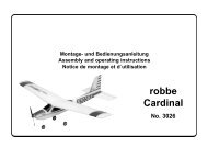
Montage- und Bedienungsanleitung<br />
Assembly and operating instructions<br />
Notice de montage et de pilotage<br />
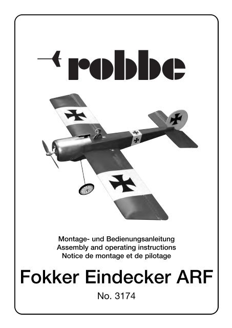
Fokker Eindecker ARF<br />
No. 3174
Technische Daten<br />
Spannweite: ca. 850 mm<br />
Rumpflänge: ca. 650 mm<br />
Gesamtflächeninhalt: ca. 15 dm 2<br />
Fluggewicht: ca. 300 g<br />
Gesamtflächenbelastung: ca. 20 g/dm 2<br />
Vorwort, Hinweise zur Bauanleitung<br />
Vielen Dank, daß Sie sich für dieses robbe Produkt entschieden<br />
haben. Hierbei handelt es sich um einen ARF- (Almost Ready to Fly)<br />
Baukasten, d.h. das Modell ist lackiert und vormontiert.<br />
Wir setzen bei diesem Modell eine gewisse Erfahrung des Anwenders<br />
voraus und haben die nachfolgende Bauanleitung bewußt kurz gehalten.<br />
Einige Abschnitte sind nur angerissen und sollen vielmehr als<br />
Wegweiser und Denkanstoß dienen.<br />
Der Zusammenbau des Modells erfolgt nach den einzelnen Fotos, die<br />
auch die Reihenfolge vorgeben. Textlich wird nur auf Punkte hingewiesen,<br />
die besonders zu beachten sind.<br />
Hinweise zur RC-Anlage<br />
Als Fernst<strong>eu</strong>erung benötigen Sie eine Anlage ab 3 Kanälen und 2<br />
Servos sowie einen elektronischen Fahrtregler mit BEC - Funktion.<br />
Zur Inbetriebnahme immer den Gasknüppel in Stellung „Motor aus“<br />
bringen, den Sender einschalten. Erst dann den Akku anschließen.<br />
Zum Ausschalten immer die Verbindung Akku - Motorregler trennen,<br />
erst dann den Sender ausschalten.<br />
Der Zusammenbau<br />
Es wird mit Epoxy oder robbe-Foam Speed geklebt.<br />
Montage der Ruderhörner<br />
- Verstärkungsstreifen mittig auf die Unterseite des Höhenruders kleben.<br />
Loch Ø 2 mm bohren, M 2 Schraube mit Kunststoffplättchen<br />
und Mutter montieren. Anlenkung aufdrehen – Bilder 1 – 5.<br />
- Die Ruderhörner für die Querruder ebenso montieren. Die<br />
Anlenkungen rechts und links auf gleiche Höhe einstellen – Bilder<br />
6 – 8.<br />
Montage des Querruderservos<br />
- Das vorgesehene Servo von unten probeweise in die Tragfläche<br />
einsetzen. Den Ausschnitt falls erforderlich, nacharbeiten.<br />
Sperrholzstreifen aufkleben. Oberseite der Tragfläche entsprechend<br />
ausschneiden, Servo einbauen – Bilder 9 - 11.<br />
- Gabelköpfe auf die Querrudergestänge aufdrehen. Das andere<br />
Ende jeweils mit einer Z-Kröpfung versehen.<br />
- Gestänge im Servo einhängen. Gestänge durch die<br />
Tragflächenabdeckung fädeln – Bilder 12 - 14.<br />
- Tragfläche mit Abdeckung auf den Rumpf setzen und gemäß<br />
Draufsicht mittig ausrichten. Abdeckung nur auf der Tragfläche verkleben.<br />
Gabelköpfe anschließen – Bilder 15 und 16.<br />
Die Leitwerke<br />
- Schlitze für Höhenleitwerk nach hinten öffnen. Höhenleitwerk nach<br />
Draufsicht und Vorderansicht zur Tragfläche ausrichten und verkleben<br />
– Bilder 15, 17 und 18.<br />
- Sporn einkleben. Schlitz für Seitenleitwerk nach hinten öffnen<br />
Seitenleitwerk rechtwinklig zum Höhenleitwerk einkleben – Bilder<br />
15, 19 – 21.<br />
Das Höhenruderservo<br />
- Höhenruderservo einbauen,<br />
- Servo in N<strong>eu</strong>tralstellung bringen,Führungsrohr in den Rumpf einbauen.<br />
Gabelkopf auf Gestänge aufdrehen, Gestänge von hinten in<br />
Montage- und Bedienungsanleitung<br />
Fokker Eindecker ARF<br />
2<br />
No.<br />
3174<br />
den Rumpf schieben. Höhenruder mit Gabelkopf anschließen –<br />
Bild 23 - 27. Z- Kröpfung anbringen, Gestänge einhängen.<br />
- Die Motorkabel des Reglers mit Schrumpfschlauch versehen und<br />
mit einem BEC-Steckerkabel verlöten. An den Akkukabeln des<br />
Reglers eine zum Akku passende Steckverbindung anbringen –<br />
Anleitung des Reglers und Polung der Kabel beachten.<br />
- Regler und Höhenruderservo am Empfänger anschließen,<br />
Empfänger mit Doppelklebeband im Rumpf platzieren – Bild 28.<br />
- Litzenantenne des Empfängers zum Seitenleitwerk spannen.<br />
Fahrwerk und Motorhaube, Endarbeiten<br />
- Räder drehbar montieren. An der Rumpfunterseite einen Schlitz für<br />
das Fahrwerk einschneiden. Fahrwerk probeweise zwischen die<br />
zwei Spanten im Rumpf schieben.<br />
- Fahrwerk verkleben – Bilder 29 - 31.<br />
- Tragflächendübel einschieben und verkleben.<br />
- Motorhaube aufsetzen, ausrichten und beidseitig mit<br />
Blechschrauben befestigen – Bild 32.<br />
- Pilotenfigur und MG-Attrappe anfertigen und aufkleben – Bilder 33<br />
und 34.<br />
- Bei der Montage der Luftschraube und des Mitnehmers auf festen<br />
Sitz achten – Bild 35.<br />
- Tragfläche mit 4 Gummiringen am Rumpf befestigen – Bild 36.<br />
- Akku zum Auswiegen einlegen, nicht anschließen – Bild 37. Riegel<br />
für den Deckel verschrauben – Bild 38.<br />
Auswiegen, Bild 39<br />
Der Schwerpunkt liegt bei unserer Fokker bei ca. 45 mm von der<br />
Nasenleiste nach hinten gemessen. Schwerpunkt anzeichnen und<br />
Modell dort unterstützen.<br />
Die richtige Schwerpunktlage ist erreicht, wenn der Rumpf eine waagerechte<br />
Position einnimmt. Akku entsprechend im Rumpf verschieben<br />
und anschließend mit Schaumgummi gegen Verrutschen sichern.<br />
Sicherstellen, dass der Akku immer in der gleichen Position im Rumpf<br />
eingebaut wird.<br />
Funktionsprobe der Ruder, Bild 40<br />
- Knüppel und Trimmungen am Sender in Mittelstellung bringen.<br />
- Die Ruder müssen sich jetzt in N<strong>eu</strong>tralstellung befinden, ansonsten<br />
an den Gabelköpfen korrigieren.<br />
- Laufrichtung der Ruder prüfen, gegebenenfalls mit Servo-Reverse<br />
korrigieren.<br />
- Die Ausschlaggrößen der Ruder nach Maßangaben einstellen.<br />
- Laufrichtung des Motors prüfen, danach Luftschraube montieren.<br />
Bei allen Montage- Wartungs- und Einstellarbeiten niemals in den<br />
Drehkreis der Luftschraube geraten - Verletzungsgefahr.<br />
Erstflug<br />
Vor dem Erstflug die Abschnitte „Routineprüfungen vor dem Start“<br />
und „Modellbetrieb“ der Sicherheitshinweise beachten.<br />
Ein geeignetes Fluggelände und einen windstillen Tag auswählen.<br />
Das Modell kann aus der Hand und vom Boden gestartet werden.<br />
Der Start erfolgt genau gegen den Wind.<br />
robbe Modellsport GmbH & Co. KG<br />
Technische Änderungen vorbehalten
1<br />
3 4<br />
5<br />
Fokker Eindecker ARF<br />
7 8<br />
9 10<br />
3<br />
2<br />
6<br />
No.<br />
3174
11<br />
13<br />
15<br />
X1 = X2<br />
Y1 = Y2<br />
Z1 = Z2<br />
16<br />
17<br />
X1<br />
Y1<br />
Z1 90°<br />
Fokker Eindecker ARF<br />
19 20<br />
Y2<br />
X2<br />
Z2<br />
4<br />
12<br />
14<br />
18<br />
No.<br />
3174
21<br />
23<br />
Fokker Eindecker ARF<br />
25 26<br />
27 28<br />
29 30<br />
5<br />
22<br />
24<br />
No.<br />
3174
31<br />
33<br />
Fokker Eindecker ARF<br />
35 36<br />
37 38<br />
39 40<br />
45<br />
6<br />
32<br />
34<br />
Querruder, aileron, aileron<br />
Höhenruder, elevator, profond<strong>eu</strong>r<br />
No.<br />
3174<br />
12 mm<br />
12 mm<br />
10 mm<br />
10 mm
Specification<br />
Wingspan: approx. 850 mm<br />
Overall length: approx. 650 mm<br />
Total surface area: approx. 15 dm 2<br />
All-up weight: approx. 300 g<br />
Total surface area loading: approx. 20 g / dm 2<br />
Introduction, notes on the building instructions<br />
Many thanks and congratulations on your choice of a model aircraft<br />
from the robbe Modellsport range. This is an ARF (Almost Ready to<br />
Fly) model, i.e. it is supplied painted and largely factory-assembled.<br />
This model is only suitable for modellers with a certain level of experience<br />
and skill, and for this reason the building instructions have deliberately<br />
been kept short.<br />
Some procedures are only sketched-in, and should be considered<br />
simply as guidelines and sources of inspiration.<br />
The model should be assembled as shown in the stage photos, which<br />
also reflect the correct sequence of assembly. The text instructions<br />
only point out areas where particular care has to be taken.<br />
The radio control system<br />
For this model you will require a radio control system with at least<br />
three channels, together with two servos and an electronic speed<br />
controller with BEC function.<br />
Always set the throttle stick to the “motor stopped” end-point before<br />
you switch on the transmitter; do not connect the flight battery until<br />
you have done this.<br />
When switching off, always disconnect the battery from the speed<br />
controller first, and only then switch off the transmitter.<br />
Assembling the model<br />
Use epoxy or robbe Foam Speed (foam cyano) for all joints.<br />
Installing the control surface horns<br />
- Glue the reinforcing strip centrally to the underside of the elevator.<br />
Drill a 2 mm Ø hole through it, and fit the M2 screw, plastic spreader<br />
plates and nut. Screw the horn lug on the screw - Figs. 1 - 5.<br />
- Install the aileron horns using the same procedure. Set the horn<br />
lugs to the same height on both ailerons - Figs. 6 - 8.<br />
Installing the aileron servos<br />
- Trial-fit the aileron servo in the wing from the underside; trim the<br />
servo opening if required. Glue the plywood strips in place as<br />
shown. Cut away the top surface of the wing as required, then<br />
install the servo - Figs. 9 - 11.<br />
- Screw a clevis on each of the aileron pushrods, and form a Z-bend<br />
in the other end.<br />
- Connect the pushrods to the servo, and route them through the<br />
slots in the wing fairing - Figs. 12 - 14.<br />
- Place the wing and the wing fairing on the fuselage, and set it central<br />
when viewed from above. Glue the fairing to the wing only.<br />
Connect the aileron clevises - Figs. 15 and 16.<br />
Tail panels<br />
- Open the tailplane slots at the rear. Align the tailplane with the wing<br />
when viewed from above and the front; glue it in place - Figs. 15,<br />
17 and 18.<br />
- Glue the tailskid in place. Open the fin slot to the rear. Glue the fin<br />
in place at right-angles to the tailplane - Figs. 15, 19 - 21.<br />
Elevator servo<br />
- Install the elevator servo.<br />
- Set the servo to n<strong>eu</strong>tral, and install the pushrod sleeve in the fuselage.<br />
Screw the clevis on the pushrod, and fit the pushrod in the<br />
Assembly and operating instructions<br />
Fokker Eindecker ARF<br />
7<br />
fuselage from the tail end. Connect the clevis to the elevator - Figs.<br />
23 - 27. Form the Z-bend at the front end of the pushrod and connect<br />
it to the servo.<br />
- Fit short pieces of heat-shrink sleeving on the motor cables attached<br />
to the speed controller, and solder a BEC plug lead to the<br />
wires. Solder a matching socket to the battery cables attached to<br />
the speed controller - take care to maintain correct polarity when<br />
connecting the cables; read the controller instructions.<br />
- Connect the speed controller and the elevator servo to the receiver,<br />
then fix the receiver to the fuselage side using double-sided<br />
foam tape - Fig. 28.<br />
- Tension the receiver aerial to the fin.<br />
Undercarriage and cowl, final work<br />
- Fit the wheels and check that they rotate freely. Cut a slot in the<br />
underside of the fuselage for the undercarriage. Check that the<br />
undercarriage fits snugly between the two formers in the fuselage.<br />
- Glue the undercarriage in place - Figs. 29 - 31.<br />
- Fit the wing dowels and glue them in place.<br />
- Fit the cowl on the model, position it carefully and attach it using<br />
self-tapping screws on both sides - Fig. 32.<br />
- Complete the pilot figure and dummy machine gun and glue them<br />
to the fuselage as shown - Figs. 33 and 34.<br />
- Fit the propeller and propeller driver on the electric motor; ensure<br />
that they are firmly secured - Fig. 35.<br />
- Fix the wing to the fuselage using four rubber bands - Fig. 36.<br />
- Place the flight battery in the fuselage to check the model’s balance;<br />
don’t connect it at this stage - Fig. 37. Screw the hatch turnbuckle<br />
in place - Fig. 38.<br />
Balancing, Fig. 39<br />
The Centre of Gravity of our Fokker is approximately 45 mm aft of the<br />
root leading edge. Mark the CG position and support the model at<br />
that point.<br />
The model is balanced correctly when it hangs approximately level.<br />
Adjust the position of the battery until the aeroplane balances as described,<br />
then pack foam rubber round the pack to prevent it shifting.<br />
Mark the position of the battery in the fuselage, so that you can easily<br />
replace it in the same position after removing it.<br />
Checking the control systems, Fig. 40<br />
- Set the transmitter sticks and trims to centre.<br />
- The control surfaces should now be at n<strong>eu</strong>tral (centre); if not, adjust<br />
the clevises to correct.<br />
- Check the direction of movement (the “sense”) of the control surfaces,<br />
and use your transmitter’s servo reverse facilities if they are<br />
not correct.<br />
- Set the control surface travels as stated in Fig. 40.<br />
- Check the direction of rotation of the motor shaft, then fit the propeller.<br />
Caution: during all these stages, i.e. when assembling, maintaining<br />
and adjusting the model, keep well clear of the rotational plane of<br />
the propeller - injury hazard.<br />
First flights<br />
Before attempting the first flight please read the sections in the<br />
Safety Notes entitled “Routine pre-flight checks” and “Flying the<br />
model”.<br />
Seek out a large, flat, open field for your flying site, and wait for a day<br />
with little or no wind. The model can be hand-launched or taken off<br />
from the ground.<br />
The model must be launched directly into wind.<br />
robbe Modellsport GmbH & Co. KG<br />
We reserve the right to alter technical specifications.<br />
No.<br />
3174
Caractéristiques techniques<br />
Envergure : approx. 850 mm<br />
Longu<strong>eu</strong>r du fuselage : approx. 650 mm<br />
Surface alaire totale : approx. 15 dm 2<br />
Poids en ordre de vol : approx. 300 g<br />
Charge alaire à la surface totale : approx. 20 g/dm 2<br />
Avant-propos<br />
Consignes concernant la notice de construction<br />
Merci d’avoir choisi un produit de la gamme robbe. Il s’agit d’une<br />
boîte de construction de modèle réduit du type prêt à voler ARF-<br />
(Almost Ready to Fly), c’est-à-dire que le modèle est peint et préassemblé.<br />
En ce qui concerne ce modèle nous partons du principe que son utilisat<strong>eu</strong>r<br />
dispose d’une certaine expérience et fournissons de ce fait<br />
une notice de construction relativement courte.<br />
Un certain nombre de manipulations ne sont que suggérées et doivent<br />
être considérées plutôt comme des remarques indicatrices et<br />
des esquisses.<br />
L’assemblage du modèle intervient selon les photos de la notice qui<br />
fournissent grossièrement la séquence de l’assemblage décrite avec<br />
des détails dont il faut tenir compte,<br />
Recommandations concernant l’ensemble de radiocommande<br />
Pour piloter le modèle nous recommandons un ensemble de radiocommande<br />
à partir de 3 voies en liaison avec 2 servos et un variat<strong>eu</strong>r<br />
électronique avec fonction d'alimentation directe du récept<strong>eu</strong>r (BEC).<br />
Pour la mise en service disposer systématiquement le manche des<br />
gaz en position „Mot<strong>eu</strong>r arrêt“, mettre l'émett<strong>eu</strong>r en marche.<br />
Raccorder l'accu.<br />
Pour couper l'ensemble de radiocommande désolidariser d'abord<br />
la connexion entre l'accu et le variat<strong>eu</strong>r, en suite coupe l'émett<strong>eu</strong>r.<br />
L’assemblage du modèle<br />
Coller avec de la colle époxy ou avec le produit robbe Foam Speed.<br />
Montage des guignols<br />
- Coller les bandes de renfort au centre de l’intrados de la gouverne<br />
de profond<strong>eu</strong>r. Percer le trou indiqué de Ø 2 mm, Monter la vis M<br />
2 avec la plaque en plastique et l’écrou approprié. Visser l’asservissement<br />
en place – photos 1 – 5.<br />
- Monter également les guignols des ailerons. Régler les asservissements<br />
à gauche et à droite à même haut<strong>eu</strong>r – photos 6 – 8.<br />
Montage du servo des ailerons<br />
- Installer le servo prévu par-dessous, à titre d’essai dans l’aile. Si<br />
nécessaire, réaménager le logement de l’accu.<br />
Coller les bandes de contre-plaqué. Découper l’extrados de l’aile<br />
en conséquence et installer le servo – photos 9 - 11.<br />
- Visser les chapes sur la timonerie des ailerons. Munir l’autre extrémité<br />
systématiquement d’un cintrage en Z.<br />
- Accrocher la timonerie dans la servo. Enfiler la timonerie au travers<br />
de la couverture de l’aile – photos 12 - 14.<br />
- Installer l’aile avec la couverture sur le fuselage et en fonction des<br />
indications de la vue plongeante, l’aligner au mili<strong>eu</strong>. Ne coller la<br />
couverture qu’à l’aile. Raccorder les chapes – photos 15 et 16.<br />
Les empennages<br />
- Ouvrir les fentes pour le stabilisat<strong>eu</strong>r vers l’arrière Aligner et coller<br />
le stabilisat<strong>eu</strong>r selon les indications de la vue plongeante et de la<br />
vue de face – fig. 15, 17 et 18.<br />
- Coller l’éperon. Ouvrir la fente de la dérive vers l’arrière Coller la<br />
dérive à angle droit par rapport au stabilisat<strong>eu</strong>r – fig. 15, 19 – 21.<br />
Le servo de profond<strong>eu</strong>r<br />
- Monter le servo de la gouverne de profond<strong>eu</strong>r,<br />
- Amener le servo au n<strong>eu</strong>tre, installer le tube-guide dans le fuselage.<br />
Visser la chape sur la timonerie, introduire la timonerie de l’arrière<br />
dans le fuselage. Raccorder la gouverne de profond<strong>eu</strong>r à la chape<br />
fig. 23 - 27. Cintrer l’extrémité de la timonerie en Z, accrocher la<br />
timonerie.<br />
- Munir les brins du variat<strong>eu</strong>r à destination du mot<strong>eu</strong>r de morceaux<br />
de gaine thermo-rétractable et les souder à un cordon-connect<strong>eu</strong>r<br />
Notice de montage et de pilotage<br />
Fokker Eindecker ARF<br />
8<br />
BEC. Sur le cordon du variat<strong>eu</strong>r à destination de l’accu, installer un<br />
connect<strong>eu</strong>r approprié à l’accu – Observer les indications fournies<br />
par la notice du variat<strong>eu</strong>r et les polarités des cordons.<br />
- Raccorder le variat<strong>eu</strong>r et le servo de profond<strong>eu</strong>r au récept<strong>eu</strong>r,<br />
Installer le récept<strong>eu</strong>r avec des morceaux de ruban adhésif double<br />
face dans le fuselage – photo 28.<br />
- Tendre l’antenne souple du récept<strong>eu</strong>r vers la dérive.<br />
Atterriss<strong>eu</strong>r et capot-mot<strong>eu</strong>r, Travaux de finition<br />
- Enfiler les rondelles-entretoises “K” et les fixer avec de la colle.<br />
Monter les roues de manière qu’elles conservent l<strong>eu</strong>r mobilité.<br />
Entailler une gorge dans l’intrados du fuselage pour l’atterriss<strong>eu</strong>r. À<br />
titre d’essai, installer l’atterriss<strong>eu</strong>r entre les couples dans le fuselage.<br />
- Coller l’atterriss<strong>eu</strong>r – photos 29 - 31.<br />
- Mettre la cheville d’aile en place et la coller.<br />
- Mettre le capot mot<strong>eu</strong>r en place, l’aligner et le fixer bilatéralement<br />
avec des vis autotaraud<strong>eu</strong>ses – fig. 32<br />
- Réaliser la figurine du pilote et la mitraill<strong>eu</strong>se factice et les coller en<br />
place – photos 33 et 34.<br />
- Lors du montage de l’hélice et de l’entraîn<strong>eu</strong>r d’hélice veiller à ce<br />
qu’ils soient particulièrement bien installés – photo 35.<br />
- Fixer l’aile avec quatre élastiques sur le fuselage – photo 36.<br />
- Mettre l’accu en place pour procéder à l’équilibrage du modèle, ne<br />
pas le raccorder pour l’instant – photo 37. Visser le verrou du couvercle<br />
– photo 38.<br />
Équilibrage, photo 39<br />
Le centre de gravité du modèle Fokker se trouve à environ 45 mm<br />
vers l’arrière à partir du bord d’attaque de l’aile. Repérer le centre de<br />
gravité sur le modèle et y caler le modèle à cet endroit.<br />
Le positionnement du centre de gravité est parfait lorsque le fuselage<br />
reste en équilibre parfaitement horizontal. Décaler l’accu en conséquence<br />
dans le fuselage et le caler ensuite avec de la mousse plastique<br />
de manière qu’i ne puisse pas se déplacer en vol.<br />
S’assurer que l’accu est toujours installé dans la même position dans<br />
le fuselage.<br />
Essai de fonctionnement des gouvernes, photo 40<br />
- Disposer les manches et les dispositifs de réglage de précision<br />
(trim) sur l’émett<strong>eu</strong>r en position médiane.<br />
- Les gouvernes doivent alors également se trouver en position n<strong>eu</strong>tre,<br />
sic e n’est pas le cas, effectuer les correction nécessaires sur<br />
les chapes.<br />
- Contrôler le sens de débattement des gouvernes, si nécessaire,<br />
corriger avec le dispositif d’inversion de la course de servos sur l’émett<strong>eu</strong>r.<br />
- Établir la grand<strong>eu</strong>r de débattement des gouvernes en fonction des<br />
cotes fournies par la notice.<br />
- Contrôler le sens de rotation du mot<strong>eu</strong>r et, ensuite, monter l’hélice.<br />
Pour tous les travaux de montage, de maintenance et de mise au<br />
point, veiller à ne jamais engager les mains dans le plan de rotation<br />
de l’hélice – danger de blessure.<br />
Le premier vol<br />
Avant le premier vol, lire attentivement les paragraphes „Contrôles de<br />
routine avant le décollage“ et „mise en œuvre du modèle“ en observant<br />
particulièrement les consignes de sécurité.<br />
Choisir un terrain de vol approprié et autant que possible un jour à<br />
vent faible.<br />
Il est possible de lancer le modèle à la main et de le faire décoller du<br />
sol.<br />
Le décollage doit intervenir exactement face au vent.<br />
robbe Modellsport GmbH & Co. KG<br />
Sous réserve de modification technique<br />
robbe Form GAF<br />
réf.<br />
3174