Anleitung für Montage, Betrieb und Wartung Installation ... - Hormann
Anleitung für Montage, Betrieb und Wartung Installation ... - Hormann
Anleitung für Montage, Betrieb und Wartung Installation ... - Hormann

Create successful ePaper yourself
Turn your PDF publications into a flip-book with our unique Google optimized e-Paper software.
ENGLISH<br />
When a hand transmitter / receiver set is included, the top<br />
button on the hand transmitter is generally already programmed<br />
into the receiver.<br />
For information on how to programme in hand transmitter<br />
buttons on other receivers, please refer to the instructions<br />
supplied with the receiver.<br />
Note<br />
Completely unroll the aerial wire and fasten to the garage<br />
ceiling, if possible upwards as well as diagonally in the<br />
direction of the structural opening. In doing so, do not wind<br />
the aerial wire aro<strong>und</strong> metal parts such as nails, braces etc.<br />
The best alignment to achieve an optimum range must be<br />
established by trial and error.<br />
868 MHz: GSM 900 mobile phones used at the same time<br />
may influence the range of the radio remote control.<br />
3.5.2 Connecting external IMPULSE buttons to start<br />
or stop door travel cycles<br />
One or several buttons with normally open (n.o.) contacts<br />
(potential-free), such as internal buttons or key switches,<br />
are connected (in the case of the latter, then joined<br />
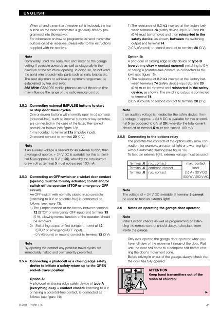
parallel) as follows (see figure 12):<br />
1) first contact to terminal 21a (impulse input).<br />
2) second contact to terminal 20 (0 V).<br />
Note<br />
If an auxiliary voltage is needed for an external button, then<br />
a voltage of approx. + 24 V DC is available for this at terminal<br />
5 (as opposed to 0 V at 20), whereby the total current<br />
drawn off at terminal 5 must not exceed 100 mA.<br />
3.5.3 Connecting an OFF-switch or a wicket door contact<br />
(opening must be forcibly actuated) to halt and/or<br />
switch off the operator (STOP or emergency-OFF<br />
circuit)<br />
An OFF-switch with normally closed (n.c.) contacts<br />
(switching to 0 V or potential-free) is connected as<br />
follows (see figure 13):<br />
1) The jumper inserted at the factory between terminal<br />
12 (STOP or emergency-OFF input) and terminal 13<br />
(0 V), allowing normal function of the operator, should<br />
be removed.<br />
2) - Switching output or first contact at terminal 12<br />
(STOP or emergency-OFF input).<br />
- 0 V (Gro<strong>und</strong>) or second contact to terminal 13 (0 V).<br />
Note<br />
By opening the contact any possible travel cycles are<br />
immediately halted and permanently prevented.<br />
3.5.4 Connecting a photocell or a closing edge safety<br />
device to initiate a safety return up to the OPEN<br />
end-of-travel position<br />
Option A:<br />
A photocell or closing edge safety device of type A<br />
(everything okay = contact closed) switching to 0 V<br />
or having a potential-free contact, is connected as<br />
follows (see figure 14):<br />
06.2004 TR10A014 RE<br />
1) The resistance of 8.2 kΩ inserted at the factory between<br />
terminals 74 (safety device-input SE) and 20<br />
(0 V) must be removed and then reinserted in the<br />
safety device, as shown, between the switching<br />
output and terminal 74.<br />
2) 0 V (Gro<strong>und</strong>) or second contact to terminal 20 (0 V).<br />
Option B:<br />
A photocell or closing edge safety device of type B<br />
(everything okay = contact opened) switching to 0 V<br />
or having a potential-free contact, is connected as follows<br />
(see figure 15):<br />
1) The resistance of 8.2 kΩ inserted at the factory between<br />
terminals 74 (safety device-input SE) and 20<br />
(0 V) must be removed and reinserted in the safety<br />
device, as shown. The switching output is connected<br />
to terminal 74.<br />
2) 0 V (Gro<strong>und</strong>) or second contact to terminal 20 (0 V).<br />
Note<br />
If an auxiliary voltage is needed for the safety device, then<br />
a voltage of approx. + 24 V DC is available for this at terminal<br />
5 (as opposed to 0 V at 20), whereby the total current<br />
drawn off at terminal 5 must not exceed 100 mA.<br />
3.5.5 Connecting to the options relay<br />
The potential-free contacts of the options relay allow connection,<br />
for example, an external light or a warning light<br />
without automatic flashing (see figure 16).<br />
To feed an external light, external voltage must be used!<br />
Terminal .6 n.c. contact max. contact<br />
Terminal .5 common contact load:<br />
Terminal .8 n.o. contact 2,5 A / 30 V DC<br />
500 W / 250 V AC<br />
Note<br />
The voltage of + 24 V DC available at terminal 5 cannot<br />
be used to feed an external light!<br />
3.6 Notes on operating the garage door operator<br />
Note<br />
Initial function checks as well as programming or extending<br />
the remote control should always take place from<br />
inside the garage.<br />
Only ever operate the garage door operator when you<br />
have full view of the movement range of the door. Wait<br />
until the door has come to a complete halt before entering<br />
the door's movement zone.<br />
Before driving in or out of the garage, always check that<br />
the door has fully opened.<br />
ATTENTION<br />
Keep hand transmitters out of the<br />
reach of children!<br />
➤<br />
41