Schutzbeschlag - Security plate Montageanleitung Fixing ... - Glutz
Schutzbeschlag - Security plate Montageanleitung Fixing ... - Glutz
Schutzbeschlag - Security plate Montageanleitung Fixing ... - Glutz

You also want an ePaper? Increase the reach of your titles
YUMPU automatically turns print PDFs into web optimized ePapers that Google loves.
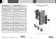
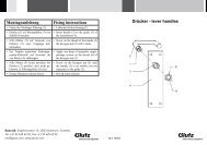
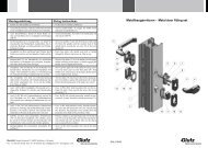
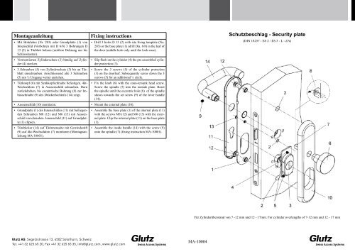
<strong>Montageanleitung</strong> <strong>Fixing</strong> instructions<br />
• Mit Bohrlehre (Nr. 203) oder Grundplatte (1) von<br />
Innenschild (Vorbohren mit D 6/8) 3 Bohrungen D<br />
13 (2) in Türblatt bohren (mittlere Bohrung nur bis<br />
Schlosskasten).<br />
• Vormontierten Zylinderschutz (3) bündig auf Zylinder<br />
(4) stecken.<br />
• 3 Schrauben (5) von Zylinderschutz (3) bis an Türblatt<br />
einschrauben. Anschliessend alle 3 Schrauben<br />
(5) um ½ Umgang weiter anziehen.<br />
• Türknopf (6) mit Senkkopfschraube befestigen. 4kt-<br />
Wechseldorn (7) in Aussenschild schrauben. Dorn<br />
zurückdrehen, bis exzentrische Bohrung (8) zur Imbusschraube<br />
(9) des Drückerlochteils (14) zeigt.<br />
<strong>Glutz</strong> AG, Segetzstrasse 13, 4502 Solothurn, Schweiz<br />
Tel. +41 32 625 65 20, Fax +41 32 625 65 35, info@glutz.com, www.glutz.com<br />
• Drill 3 holes D 13 (2) with site fixing tem<strong>plate</strong> (No.<br />
203) or the base <strong>plate</strong> (1) (drill Dia. 6/8) in the leaf of<br />
the door (middle hole only until the lock-case).<br />
• Slip flush on the cylinder (4) the pre assembled cylinder<br />
protection (3).<br />
• Screw the 3 screws (5) of the cylinder protection<br />
(3) on the doorleaf. Subsequently screw down the 3<br />
screws (5) for an additional ½ circle.<br />
• Fix the knob (6) with the coun-tersunk head screw.<br />
Screw the spindle (7) into the outside <strong>plate</strong>. Reset<br />
the spindle until the eccentric hole (8) of the spindle<br />
shows towards the set screw (9) of the lever handle<br />
(14).<br />
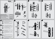
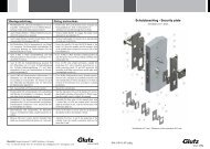
• Aussenschild (10) montieren. • Mount the external <strong>plate</strong> (10).<br />
• Grundplatte (1) des Innenschildes (11) mit beiliegenden<br />
Schrauben M8 (12) und M6 (13) mit Aussenschild<br />
verschrauben. Innenschild (11) auf Grundplatte<br />
(1) clipsen.<br />
• Türdrücker (14) auf Türinnenseite mit Gewindestift<br />
(9) auf 4kt-Wechseldorn (7) montieren (<strong>Montageanleitung</strong><br />
MA-10001).<br />
• Assemble the base <strong>plate</strong> (1) of the internal <strong>plate</strong> (11)<br />
with the screws M8 (12) and M6 (13) with the external<br />
<strong>plate</strong>. Clip the internal <strong>plate</strong> (11) on the base <strong>plate</strong><br />
(1).<br />
• Assemble the inside handle (14) with the screw (9)<br />
onto the spindle (7) (fixing instruction MA-10001).<br />
MA-10004<br />
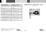
<strong>Schutzbeschlag</strong> - <strong>Security</strong> <strong>plate</strong><br />
(DIN 18257 - ES 2 / ES 3 - L - ZA)<br />
Für Zylinderüberstand von 7 -12 mm und 12 - 17mm. For cylinder overlengths of 7-12 mm and 12 - 17 mm
Mode d’emploi Istruzioni di montaggio<br />
• Percer les 3 perçages D 13 (2) au moyen du gabarit de perçage<br />
(No. 203) ou de la plaque de base (1) (percer avec D<br />
6/8) (le trou du milieu seulement jusqu’à la serrure).<br />
• Attacher la protection du cylin-dre (3) à fleur sur le cylindre<br />
(4).<br />
• Visser les 3 vis (5) de la protec-tion du cylindre (3) à la<br />
porte. Ensuite serrer tous les 3 vis (5) pour tour supplémentaire.<br />
• Fixer le bouton (6) ou moyen du boulon à tête conique.<br />
Visser la tige carrée (7) dans l’entrée extérieure jusqu’au<br />
fond. Ensuite dévisser la tige jusqu’à ce que le trou excentrique<br />
(8) de la tige soit placé du coté de la vis de blocage<br />
(9) de la poignée (14).<br />
<strong>Glutz</strong> AG, Segetzstrasse 13, 4502 Solothurn, Schweiz<br />
Tel. +41 32 625 65 20, Fax +41 32 625 65 35, info@glutz.com, www.glutz.com<br />
• Praticare 3 fori D 13 (2) nel battente con la dima di foratura<br />
(n. 203) o la piastra di base (1) della placca interna (preforare<br />
con D 6/8) (foro centrale solo fino alla scatola).<br />
• Inserire la protezione premontata (3) a filo sul cilindro<br />
(4).<br />
• Avvitare le 3 viti (5) della protezione del cilindro (3) fino<br />
al battente. Quindi serrare ulteriormente di mezzo giro<br />
tutte e 3 le viti (5).<br />
• Fermare il pomello (6) con la vite a testa svasata. Avvitare<br />
il perno quadro (7) sulla placca esterna. Ruotare il perno<br />
quadro in senso antiorario fino a quando il foro eccentrico<br />
(8) punta verso la vite Allen (9) della maniglia (14).<br />
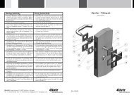
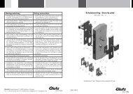
• Monter l’entrée extérieure (10). • Montare la placca esterna (10).<br />
• Visser la plaque de base (1) de l’entrée intérieure (11)<br />
avec des vis M8 (12) et M6 (13) sur l’entrée extérieure.<br />
Clipser l’entrée intérieure (11) sur la plaque de base (1).<br />
• Monter la poignée (14) au moyen de la vis (9) à l’intérieur<br />
sur la tige (7).<br />
• Avvitare la piastra di base (1) della placca interna (11) alla<br />
placca esterna con le viti M8 (12) e M6 (13) in dotazione.<br />
Agganciare la placca interna (11) alla piastra di base (1).<br />
• Montare la maniglia (14) con il perno filettato (9) sul perno<br />
quadro fielttato (7).<br />
MA-10004<br />
Entrée de sécurité - Ferramenta di sicurezza<br />
(DIN 18257 - ES 2 / ES 3 - L - ZA)<br />
Pour dépassement de cy-lindre 7-12mm et 12-17mm