Classic® 50 212/410 - Peavey
Classic® 50 212/410 - Peavey
Classic® 50 212/410 - Peavey

You also want an ePaper? Increase the reach of your titles
YUMPU automatically turns print PDFs into web optimized ePapers that Google loves.
Classic ® <strong>50</strong> <strong>212</strong>/<strong>410</strong><br />
GUITAR AMPLIFIER<br />
Operating<br />
Manual<br />
www.peavey.com
Intended to alert the user to the presence of uninsulated “dangerous voltage” within the product’s<br />
enclosure that may be of sufficient magnitude to constitute a risk of electric shock to persons.<br />
Intended to alert the user of the presence of important operating and maintenance (servicing)<br />
instructions in the literature accompanying the product.<br />
CAUTION: Risk of electrical shock — DO NOT OPEN!<br />
CAUTION: To reduce the risk of electric shock, do not remove cover. No user serviceable parts inside.<br />
Refer servicing to qualified service personnel.<br />
WARNING: To prevent electrical shock or fire hazard, this apparatus should not be exposed to rain or<br />
moisture‚ and objects filled with liquids‚ such as vases‚ should not be placed on this apparatus. Before<br />
using this apparatus‚ read the operating guide for further warnings.<br />
Este símbolo tiene el propósito, de alertar al usuario de la presencia de “(voltaje) peligroso” sin<br />
aislamiento dentro de la caja del producto y que puede tener una magnitud suficiente como para<br />
constituir riesgo de descarga eléctrica.<br />
Este símbolo tiene el propósito de alertar al usario de la presencia de instruccones importantes sobre la<br />
operación y mantenimiento en la información que viene con el producto.<br />
PRECAUCION: Riesgo de descarga eléctrica ¡NO ABRIR!<br />
PRECAUCION: Para disminuír el riesgo de descarga eléctrica, no abra la cubierta. No hay piezas útiles<br />
dentro. Deje todo mantenimiento en manos del personal técnico cualificado.<br />
ADVERTENCIA: Para prevenir choque electrico o riesgo de incendios, este aparato no se debe exponer a<br />
la lluvia o a la humedad. Los objetos llenos de liquidos, como los floreros, no se deben colocar encima<br />
de este aparato. Antes de usar este aparato, lea la guia de funcionamiento para otras advertencias.<br />
Ce symbole est utilisé dans ce manuel pour indiquer à l’utilisateur la présence d’une tension dangereuse<br />
pouvant être d’amplitude suffisante pour constituer un risque de choc électrique.<br />
Ce symbole est utilisé dans ce manuel pour indiquer à l’utilisateur qu’il ou qu’elle trouvera d’importantes<br />
instructions concernant l’utilisation et l’entretien de l’appareil dans le paragraphe signalé.<br />
ATTENTION: Risques de choc électrique — NE PAS OUVRIR!<br />
ATTENTION: Afin de réduire le risque de choc électrique, ne pas enlever le couvercle. Il ne se trouve<br />
à l’intérieur aucune pièce pouvant être reparée par l’utilisateur. Confiez I’entretien et la réparation de<br />
l’appareil à un réparateur <strong>Peavey</strong> agréé.<br />
AVIS: Dans le but de reduire les risques d’incendie ou de decharge electrique, cet appareil ne doit<br />
pas etre expose a la pluie ou a l’humidite et aucun objet rempli de liquide, tel qu’un vase, ne doit<br />
etre pose sur celui-ci. Avant d’utiliser de cet appareil, lisez attentivement le guide fonctionnant pour<br />
avertissements supplémentaires.<br />
Dieses Symbol soll den Anwender vor unisolierten gefährlichen Spannungen innerhalb des Gehäuses<br />
warnen, die von Ausreichender Stärke sind, um einen elektrischen Schlag verursachen zu können.<br />
Dieses Symbol soll den Benutzer auf wichtige Instruktionen in der Bedienungsanleitung aufmerksam<br />
machen, die Handhabung und Wartung des Produkts betreffen.<br />
VORSICHT: Risiko — Elektrischer Schlag! Nicht öffnen!<br />
VORSICHT: Um das Risiko eines elektrischen Schlages zu vermeiden, nicht die Abdeckung enfernen.<br />
Es befinden sich keine Teile darin, die vom Anwender repariert werden könnten. Reparaturen nur von<br />
qualifiziertem Fachpersonal durchführen lassen.<br />
WARNUNG: Um elektrischen Schlag oder Brandgefahr zu verhindern, sollte dieser Apparat nicht<br />
Regen oder Feuchtigkeit ausgesetzt werden und Gegenstände mit Flüssigkeiten gefuellt, wie Vasen,<br />
nicht auf diesen Apparat gesetzt werden. Bevor dieser Apparat verwendet wird, lesen Sie bitte den<br />
Funktionsführer für weitere Warnungen.<br />
2
IMPORTANT SAFETY INSTRUCTIONS<br />
WARNING: When using electrical products, basic cautions should always be followed, including the following:<br />
1. Read these instructions.<br />
2. Keep these instructions.<br />
3. Heed all warnings.<br />
4. Follow all instructions.<br />
5. Do not use this apparatus near water.<br />
6. Clean only with a dry cloth.<br />
7. Do not block any of the ventilation openings. Install in accordance with manufacturer’s instructions.<br />
8. Do not install near any heat sources such as radiators, heat registers, stoves or other apparatus (including amplifiers) that<br />
produce heat.<br />
9. Do not defeat the safety purpose of the polarized or grounding-type plug. A polarized plug has two blades with one wider than<br />
the other. A grounding type plug has two blades and a third grounding plug. The wide blade or third prong is provided for your<br />
safety. If the provided plug does not fit into your outlet, consult an electrician for replacement of the obsolete outlet.<br />
10. Protect the power cord from being walked on or pinched, particularly at plugs, convenience receptacles, and the point they exit<br />
from the apparatus.<br />
11. Only use attachments/accessories provided by the manufacturer.<br />
12. Use only with a cart, stand, tripod, bracket, or table specified by the manufacturer, or sold with the apparatus. When a cart is<br />
used, use caution when moving the cart/apparatus combination to avoid injury from tip-over.<br />
13. Unplug this apparatus during lightning storms or when unused for long periods of time.<br />
14. Refer all servicing to qualified service personnel. Servicing is required when the apparatus has been damaged in any way, such<br />
as power-supply cord or plug is damaged, liquid has been spilled or objects have fallen into the apparatus, the apparatus has<br />
been exposed to rain or moisture, does not operate normally, or has been dropped.<br />
15. Never break off the ground pin. Write for our free booklet “Shock Hazard and Grounding.” Connect only to a power supply of the<br />
type marked on the unit adjacent to the power supply cord.<br />
16. If this product is to be mounted in an equipment rack, rear support should be provided.<br />
17. Note for UK only: If the colors of the wires in the mains lead of this unit do not correspond with the terminals in your plug‚<br />
proceed as follows:<br />
a) The wire that is colored green and yellow must be connected to the terminal that is marked by the letter E‚ the earth symbol‚<br />
colored green or colored green and yellow.<br />
b) The wire that is colored blue must be connected to the terminal that is marked with the letter N or the color black.<br />
c) The wire that is colored brown must be connected to the terminal that is marked with the letter L or the color red.<br />
18. This electrical apparatus should not be exposed to dripping or splashing and care should be taken not to place objects<br />
containing liquids, such as vases, upon the apparatus.<br />
19. The on/off switch in this unit does not break both sides of the primary mains. Hazardous energy can be present inside the<br />
chassis when the on/off switch is in the off position. The mains plug or appliance coupler is used as the disconnect device, the<br />
disconnect device shall remain readily operable.<br />
20. Exposure to extremely high noise levels may cause a permanent hearing loss. Individuals vary considerably in susceptibility to<br />
noise-induced hearing loss, but nearly everyone will lose some hearing if exposed to sufficiently intense noise for a sufficient<br />
time. The U.S. Government’s Occupational Safety and Health Administration (OSHA) has specified the following permissible<br />
noise level exposures:<br />
Duration Per Day In Hours Sound Level dBA, Slow Response<br />
8 90<br />
6 92<br />
4 95<br />
3 97<br />
2 100<br />
1 1⁄2 102<br />
1 105<br />
1⁄2 110<br />
1⁄4 or less 115<br />
According to OSHA, any exposure in excess of the above permissible limits could result in some hearing loss. Ear plugs or protectors to<br />
the ear canals or over the ears must be worn when operating this amplification system in order to prevent a permanent hearing loss, if<br />
exposure is in excess of the limits as set forth above. To ensure against potentially dangerous exposure to high sound pressure levels, it is<br />
recommended that all persons exposed to equipment capable of producing high sound pressure levels such as this amplification system be<br />
protected by hearing protectors while this unit is in operation.<br />
SAVE THESE INSTRUCTIONS!
WICHTIGE SICHERHEITSHINWEISE<br />
ACHTUNG: Beim Einsatz von Elektrogeräten müssen u.a. grundlegende Vorsichtsmaßnahmen befolgt werden:<br />
1. Lesen Sie sich diese Anweisungen durch.<br />
2. Bewahren Sie diese Anweisungen auf.<br />
3. Beachten Sie alle Warnungen.<br />
4. Befolgen Sie alle Anweisungen.<br />
5. Setzen Sie dieses Gerät nicht in der Nähe von Wasser ein.<br />
6. Reinigen Sie es nur mit einem trockenen Tuch.<br />
7. Blockieren Sie keine der Lüftungsöffnungen. Führen Sie die Installation gemäß den Anweisungen des Herstellers durch.<br />
8. Installieren Sie das Gerät nicht neben Wärmequellen wie Heizungen, Heizgeräten, Öfen oder anderen Geräten (auch Verstärkern),<br />
die Wärme erzeugen.<br />
9. Beeinträchtigen Sie nicht die Sicherheitswirkung des gepolten Steckers bzw. des Erdungssteckers. Ein gepolter Stecker weist<br />
zwei Stifte auf, von denen einer breiter ist als der andere. Ein Erdungsstecker weist zwei Stifte und einen dritten Erdungsstift auf.<br />
Der breite Stift bzw. der dritte Stift dient Ihrer Sicherheit. Sollte der beiliegende Stecker nicht in Ihre Steckdose passen, wenden<br />
Sie sich bitte an einen Elektriker, um die ungeeignete Steckdose austauschen zu lassen.<br />
10. Schützen Sie das Netzkabel, sodass niemand darauf tritt oder es geknickt wird, insbesondere an Steckern oder Buchsen und<br />
ihren Austrittsstellen aus dem Gerät.<br />
11. Verwenden Sie nur die vom Hersteller erhältlichen Zubehörgeräte oder Zubehörteile.<br />
12. Verwenden Sie nur einen Wagen, Stativ, Dreifuß, Träger oder Tisch, der den Angaben des Herstellers entspricht oder zusammen<br />
mit dem Gerät verkauft wurde. Wird ein Wagen verwendet, bewegen Sie den Wagen mit dem darauf befindlichen Gerät besonders<br />
vorsichtig, damit er nicht umkippt und möglicherweise jemand verletzt wird.<br />
13. Trennen Sie das Gerät während eines Gewitters oder während längerer Zeiträume, in denen es nicht benutzt wird, von der<br />
Stromversorgung.<br />
14. Lassen Sie sämtliche Wartungsarbeiten von qualifizierten Kundendiensttechnikern durchführen. Eine Wartung ist erforderlich,<br />
wenn das Gerät in irgendeiner Art beschädigt wurde, etwa wenn das Netzkabel oder der Netzstecker beschädigt wurden,<br />
Flüssigkeit oder Gegenstände in das Gerät gelangt sind, das Gerät Regen oder Feuchtigkeit ausgesetzt wurde, nicht normal<br />
arbeitet oder heruntergefallen ist.<br />
15. Der Erdungsstift darf nie entfernt werden. Auf Wunsch senden wir Ihnen gerne unsere kostenlose Broschüre „Shock Hazard and<br />
Grounding“ (Gefahr durch elektrischen Schlag und Erdung) zu. Schließen Sie nur an die Stromversorgung der Art an, die am<br />
Gerät neben dem Netzkabel angegeben ist.<br />
16. Wenn dieses Produkt in ein Geräte-Rack eingebaut werden soll, muss eine Versorgung über die Rückseite eingerichtet werden.<br />
17. Hinweis – Nur für Großbritannien: Sollte die Farbe der Drähte in der Netzleitung dieses Geräts nicht mit den Klemmen in Ihrem<br />
Stecker übereinstimmen, gehen Sie folgendermaßen vor:<br />
a) Der grün-gelbe Draht muss an die mit E (Symbol für Erde) markierte bzw. grüne oder grün-gelbe Klemme angeschlossen<br />
werden.<br />
b) Der blaue Draht muss an die mit N markierte bzw. schwarze Klemme angeschlossen werden.<br />
c) Der braune Draht muss an die mit L markierte bzw. rote Klemme angeschlossen werden.<br />
18. Dieses Gerät darf nicht ungeschützt Wassertropfen und Wasserspritzern ausgesetzt werden und es muss darauf geachtet<br />
werden, dass keine mit Flüssigkeiten gefüllte Gegenstände, wie z. B. Blumenvasen, auf dem Gerät abgestellt werden.<br />
19. Der Netzschalter in dieser Einheit bricht beide Seiten von den primären Haupleitungen nicht. Gerfährliche Energie kann<br />
anwesend innerhalb des Chassis sein, wenn her Netzschalter im ab Poistion ist. Die Hauptleitungen stöpseln zu oder<br />
Gerätkupplung ist benutzt, während das Vorrichtung abschaltet, das schaltet Vorrichtung wird bleiben sogleich hantierbar ab.<br />
20. Belastung durch extrem hohe Lärmpegel kann zu dauerhaftem Gehörverlust führen. Die Anfälligkeit für durch Lärm bedingten<br />
Gehörverlust ist von Mensch zu Mensch verschieden, das Gehör wird jedoch bei jedem in gewissem Maße geschädigt, der über<br />
einen bestimmten Zeitraum ausreichend starkem Lärm ausgesetzt ist. Die US-Arbeitsschutzbehörde (Occupational and Health<br />
Administration, OSHA) hat die folgenden zulässigen Pegel für Lärmbelastung festgelegt:<br />
Dauer pro Tag in Stunden Geräuschpegel dBA, langsame Reaktion<br />
8 90<br />
6 92<br />
4 95<br />
3 97<br />
2 100<br />
1 1 ⁄2 102<br />
1 105<br />
1 ⁄2 110<br />
1 ⁄4 oder weniger 115<br />
Laut OSHA kann jede Belastung über den obenstehenden zulässigen Grenzwerten zu einem gewissen Gehörverlust führen. Sollte die Belastung<br />
die obenstehenden Grenzwerte übersteigen, müssen beim Betrieb dieses Verstärkungssystems Ohrenstopfen oder Schutzvorrichtungen<br />
im Gehörgang oder über den Ohren getragen werden, um einen dauerhaften Gehörverlust zu verhindern. Um sich vor einer möglicherweise<br />
gefährlichen Belastung durch hohe Schalldruckpegel zu schützen, wird allen Personen empfohlen, die mit Geräten arbeiten, die wie dieses<br />
Verstärkungssystem hohe Schalldruckpegel erzeugen können, beim Betrieb dieses Geräts einen Gehörschutz zu tragen.<br />
BEWAHREN SIE DIESE SICHERHEITSHINWEISE AUF!
INSTRUCTIONS IMPORTANTES DE SECURITE<br />
ATTENTION: L’utilisation de tout appareil électrique doit être soumise aux precautions d’usage incluant:<br />
1. Lire ces instructions.<br />
2. Gardez ce manuel pour de futures références.<br />
3. Prétez attention aux messages de précautions de ce manuel.<br />
4. Suivez ces instructions.<br />
5. N’utilisez pas cette unité proche de plans d’eau.<br />
6. N’utilisez qu’un tissu sec pour le nettoyage de votre unité.<br />
7. N’obstruez pas les systèmes de refroidissement de votre unité et installez votre unité en fonction des instructions de ce manuel.<br />
8. Ne positionnez pas votre unité à proximité de toute source de chaleur.<br />
9. Connectez toujours votre unité sur une alimentation munie de prise de terre utilisant le cordon d’alimentation fourni.<br />
10. Protégez les connecteurs de votre unité et positionnez les cablages pour éviter toutes déconnexions accidentelles.<br />
11. N’utilisez que des fixations approuvées par le fabriquant.<br />
12. Lors de l’utilsation sur pied ou pole de support, assurez dans le cas de déplacement de l’ensemble enceinte/support de prévenir<br />
tout basculement intempestif de celui-ci.<br />
13. Il est conseillé de déconnecter du secteur votre unité en cas d’orage ou de durée prolongée sans utilisation.<br />
14. Seul un technicien agréé par le fabriquant est à même de réparer/contrôler votre unité. Celle-ci doit être contrôlée si elle a subit<br />
des dommages de manipulation, d’utilisation ou de stockage (humidité,…).<br />
15. Ne déconnectez jamais la prise de terre de votre unité.<br />
16. Si votre unité est destinée a etre montée en rack, des supports arriere doivent etre utilises.<br />
17. Note pour les Royaumes-Unis: Si les couleurs de connecteurs du cable d’alimentation ne correspond pas au guide de la prise<br />
secteur, procédez comme suit:<br />
a) Le connecteur vert et jaune doit être connectrer au terminal noté E, indiquant la prise de terre ou correspondant aux couleurs<br />
verte ou verte et jaune du guide.<br />
b) Le connecteur Bleu doit être connectrer au terminal noté N, correspondnat à la couleur noire du guide.<br />
c) Le connecteur marron doit être connectrer au terminal noté L, correspondant à la couleur rouge du guide.<br />
18. Cet équipement électrique ne doit en aucun cas être en contact avec un quelconque liquide et aucun objet contenant un liquide,<br />
vase ou autre ne devrait être posé sur celui-ci.<br />
19. L'interrupter (on-off) dans cette unité ne casse pas les deux côtés du primaire principal. L'énergie hasardeuse peut être<br />
preésente dans châssis quand l'interrupter (on-off) est dans le de la position. Le bouchon principal ou atelage d'appareil est<br />
utilisé comme le débrancher l'appareil restera facilement opérable.<br />
20. Une exposition à de hauts niveaux sonores peut conduire à des dommages de l’écoute irréversibles. La susceptibilité au bruit<br />
varie considérablement d’un individu à l’autre, mais une large majorité de la population expériencera une perte de l’écoute après<br />
une exposition à une forte puissance sonore pour une durée prolongée. L’organisme de la santé américaine (OSHA) a produit le<br />
guide ci-dessous en rapport à la perte occasionnée:<br />
Durée par Jour (heures) Niveau sonore moyen (dBA)<br />
8 90<br />
6 92<br />
4 95<br />
3 97<br />
2 100<br />
1 1 ⁄2 102<br />
1 105<br />
1 ⁄2 110<br />
1 ⁄4 ou inférieur 115<br />
D’après les études menées par le OSHA, toute exposition au delà des limites décrites ce-dessus entrainera des pertes de l’écoute chez la<br />
plupart des sujets. Le port de système de protection (casque, oreilette de filtrage,…) doit être observé lors de l’opération cette unité ou des<br />
dommages irréversibles peuvent être occasionnés. Le port de ces systèmes doit être observé par toutes personnes susceptibles d’être exposées<br />
à des conditions au delà des limites décrites ci-dessus.<br />
GARDEZ CES INSTRUCTIONS!
INSTRUCCIONES IMPORTANTES PARA SU SEGURIDAD<br />
CUIDADO: Cuando use productos electrónicos, debe tomar precauciones básicas, incluyendo las siguientes:<br />
1. Lea estas instrucciones.<br />
2. Guarde estas instrucciones.<br />
3. Haga caso de todos los consejos.<br />
4. Siga todas las instrucciones.<br />
5. No usar este aparato cerca del agua.<br />
6. Limpiar solamente con una tela seca.<br />
7. No bloquear ninguna de las salidas de ventilación. Instalar de acuerdo a las instrucciones del fabricante.<br />
8. No instalar cerca de ninguna fuente de calor como radiadores, estufas, hornos u otros aparatos (incluyendo amplificadores) que<br />
produzcan calor.<br />
9. No retire la patilla protectora del enchufe polarizado o de tipo “a Tierra”. Un enchufe polarizado tiene dos puntas, una de ellas<br />
más ancha que la otra. Un enchufe de tipo “a Tierra” tiene dos puntas y una tercera “a Tierra”. La punta ancha (la tercera ) se<br />
proporciona para su seguridad. Si el enchufe proporcionado no encaja en su enchufe de red, consulte a un electricista para que<br />
reemplaze su enchufe obsoleto.<br />
10. Proteja el cable de alimentación para que no sea pisado o pinchado, particularmente en los enchufes, huecos, y los puntos que<br />
salen del aparato.<br />
11. Usar solamente añadidos/accesorios proporcionados por el fabricante.<br />
12. Usar solamente un carro, pie, trípode, o soporte especificado por el fabricante, o vendido junto al aparato. Cuando se use un<br />
carro, tenga cuidado al mover el conjunto carro/aparato para evitar que se dañe en un vuelco. No suspenda esta caja de ninguna<br />
manera.<br />
13. Desenchufe este aparato durante tormentas o cuando no sea usado durante largos periodos de tiempo.<br />
14. Para cualquier reparación, acuda a personal de servicio cualificado. Se requieren reparaciones cuando el aparato ha sido dañado<br />
de alguna manera, como cuando el cable de alimentación o el enchufe se han dañado, algún líquido ha sido derramado o algún<br />
objeto ha caído dentro del aparato, el aparato ha sido expuesto a la lluvia o la humedad, no funciona de manera normal, o ha<br />
sufrido una caída.<br />
15. Nunca retire la patilla de Tierra.Escríbanos para obtener nuestro folleto gratuito “Shock Hazard and Grounding” (“Peligro de<br />
Electrocución y Toma a Tierra”). Conecte el aparato sólo a una fuente de alimentación del tipo marcado al lado del cable de<br />
alimentación.<br />
16. Si este producto va a ser enracado con más equipo, use algún tipo de apoyo trasero.<br />
17. Nota para el Reino Unido solamente: Si los colores de los cables en el enchufe principal de esta unidad no corresponden con los<br />
terminales en su enchufe‚ proceda de la siguiente manera:<br />
a) El cable de color verde y amarillo debe ser conectado al terminal que está marcado con la letra E‚ el símbolo de Tierra (earth)‚<br />
coloreado en verde o en verde y amarillo.<br />
b) El cable coloreado en azul debe ser conectado al terminal que está marcado con la letra N o el color negro.<br />
c) El cable coloreado en marrón debe ser conectado al terminal que está marcado con la letra L o el color rojo.<br />
18. Este aparato eléctrico no debe ser sometido a ningún tipo de goteo o salpicadura y se debe tener cuidado para no poner objetos<br />
que contengan líquidos, como vasos, sobre el aparato.<br />
19. El interruptor de en/lejos en esta unidad no rompe ambos lados de la red primaria. La energía peligrosa puede ser presente<br />
dentro del chasis cuando el interruptor de en/lejos está en el de la posición. El tapón de la red o el acoplador del aparato son<br />
utilizados como el desconecta dispositivo, el desconecta dispositivo se quedará fácilmente operable.<br />
20. La exposición a altos niveles de ruido puede causar una pérdida permanente en la audición. La susceptibilidad a la pérdida de<br />
audición provocada por el ruido varía según la persona, pero casi todo el mundo perderá algo de audición si se expone a un<br />
nivel de ruido suficientemante intenso durante un tiempo determinado. El Departamento para la Salud y para la Seguridad del<br />
Gobierno de los Estados Unidos (OSHA) ha especificado las siguientes exposiciones al ruido permisibles:<br />
Duración por Día en Horas Nivel de Sonido dBA, Respuesta Lenta<br />
8 90<br />
6 92<br />
4 95<br />
3 97<br />
2 100<br />
1 1 /2 102<br />
1 105<br />
1 /2 110<br />
1 /4 o menos 115<br />
De acuerdo al OSHA, cualquier exposición que exceda los límites arriba indicados puede producir algún tipo de pérdida en la audición.<br />
Protectores para los canales auditivos o tapones para los oídos deben ser usados cuando se opere con este sistema de sonido para prevenir<br />
una pérdida permanente en la audición, si la exposición excede los límites indicados más arriba. Para protegerse de una exposición a altos<br />
niveles de sonido potencialmente peligrosa, se recomienda que todas las personas expuestas a equipamiento capaz de producir altos niveles<br />
de presión sonora, tales como este sistema de amplificación, se encuentren protegidas por protectores auditivos mientras esta unidad<br />
esté operando.<br />
GUARDE ESTAS INSTRUCCIONES!<br />
6<br />
6
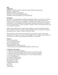
Front Panel<br />
POWER SWITCH (1)<br />
Switch to “ON” position to turn on.<br />
ENGLISH<br />
8 7<br />
STANDBY SWITCH (2)<br />
Allows amp to be placed in standby or active mode. In standby mode the tubes remain hot, but the<br />
amplifier is not operational.<br />
CHANNEL SELECT SWITCH (3)<br />
Allows selection of the Lead or Normal channels.<br />
NOTE: Channel selection may also be accomplished by the remote footswitch. If remote<br />
selection is desired the channel switch must be in the Lead position.<br />
PILOT LIGHT LED (4)<br />
Illuminates when AC power is being supplied to the amp.<br />
PRESENCE (5)<br />
An active tone control that boosts the extreme high frequencies by up to 6 dB.<br />
MASTER VOLUME (6)<br />
Controls the overall volume level of the system.<br />
TREBLE, MIDDLE, AND BASS EQ (7)<br />
Passive tone controls that regulate high, mid, and low frequencies, respectively.<br />
REVERB (8)<br />
Reverberation is an echo effect. Rotate clockwise to increase the effect. Remote footswitch can control<br />
ON/OFF.<br />
Ventilation: Allow 24" of clearance on all sides from a combustible surface.<br />
7<br />
6<br />
5<br />
WARNING<br />
THE ON/OFF SWITCH IN THIS APPARATUS<br />
DOES NOT BREAK BOTH SIDES OF THE MAINS.<br />
HAZARDOUS ENERGY MAY BE PRESENT INSIDE<br />
THE ENCLOSURE WHEN THE POWER SWITCH IS<br />
IN THE OFF POSITION.<br />
4<br />
3<br />
2<br />
1
13<br />
Front Panel<br />
12<br />
11<br />
10<br />
9<br />
POST GAIN (9)<br />
Controls the overall volume level of the Lead channel. The final level adjustment should be made after<br />
the desired sound has been achieved.<br />
PRE GAIN (10)<br />
Controls the input volume level of the Lead channel.<br />
NORMAL GAIN (11)<br />
Controls the volume level of the Normal channel.<br />
BRIGHT INPUT (12)<br />
Input for instrument-level signals. This input produces enhanced high frequency response (treble),<br />
similar to a bright switch, when compared to the normal input.<br />
NORMAL INPUT (13)<br />
Input for instrument-level signals. For brighter frequency response (highs) see Bright Input (12).<br />
8
Rear Panel<br />
14 15<br />
16<br />
FUSE (14)<br />
The fuse is located within the cap of the fuseholder. If the fuse should fail, IT MUST BE REPLACED<br />
WITH THE SAME TYPE AND VALUE IN ORDER TO AVOID DAMAGE TO THE EQUIPMENT AND TO PREVENT<br />
VOIDING THE WARRANTY. If the amp repeatedly blows fuses, it should be taken to a qualified service<br />
center for repair.<br />
WARNING: THE FUSE SHOULD ONLY BE REPLACED WHEN THE POWER CORD HAS BEEN<br />
DISCONNECTED FROM ITS POWER SOURCE.<br />
GROUND SWITCH (15)<br />
Three position rocker-type switch which, in most applications, should be operated in its center or<br />
zero position. There may be some situations when audible hum and/or noise will come from the<br />
loudspeaker. If this situation arises, position the ground switch to either positive or negative ( + or -) or<br />
until the noise is minimized.<br />
NOTE: Should the noise problem continue, consult your Authorized <strong>Peavey</strong> Dealer, the <strong>Peavey</strong><br />
Factory, or a qualified service technician. THE GROUND SWITCH IS NOT FUNCTIONAL ON<br />
220/240 VOLT MODELS.<br />
SPEAKER OUTPUTS (16)<br />
Speaker output (1/4") jacks are provided for 16 and 8 ohms. When both jacks are engaged, amplifier<br />
impedance is 8 ohms.<br />
REMOTE SWITCH JACK (17)<br />
Provided for the connection of the optional remote footswitch. Footswitch is used to select the Lead or<br />
Normal channels and defeat reverb. When using remote footswitch, always insert the plug fully (second<br />
click) to ensure proper operation.<br />
EFFECTS RETURN (18)<br />
Input for returning signals from external effects or signal processing equipment.<br />
EFFECTS SEND (19)<br />
Output for supplying signals to external effects or signal processing equipment.<br />
9<br />
17<br />
18<br />
19
POWER AMPLIFIER SECTION<br />
Four 6BQ5/EL84’s with 12AX7 driver<br />
Rated Power & Load:<br />
<strong>50</strong> W RMS into 16 or 8 ohms<br />
Power @ Clipping (Typically):<br />
(5% THD, 1 kHz, 120 V AC line)<br />
<strong>50</strong> W RMS into 16 or 8 ohms<br />
(Bias must be reduced to measure)<br />
Frequency Response:<br />
+0, -2 dB, <strong>50</strong> Hz to 15 kHz, @ 40 W RMS into 16 ohms<br />
Hum & Noise:<br />
No greater than 80 dB below rated power<br />
Power Consumption:<br />
200 watts, <strong>50</strong>/60 Hz, 120 VAC (Domestic)<br />
PREAMP SECTION<br />
Two 12AX7’s<br />
The following specs are measured @ 1 kHz with the controls<br />
preset as follows:<br />
Pre & Post (lead) @ 0<br />
Reverb Level @ 0<br />
Bass & Treble EQ @ 12<br />
Middle EQ @ 0<br />
Master Volume @ 12<br />
Presence @ 6<br />
Nominal level is with Input Gain @ 6.<br />
Minimum level is with Input Gain @ 12.<br />
Preamp Normal Input:<br />
Impedance: Very high Z, 470 K ohms<br />
Lead Channel (Post Gain @ 10):<br />
Nominal Input Level:<br />
-40 dBV, 10 mV RMS<br />
Minimum Input Level:<br />
-70 dBV, 0.3 mV RMS<br />
Classic ® <strong>50</strong><br />
Guitar Amplifier<br />
SPECIFICATIONS<br />
10<br />
PREAMP SECTION, continued<br />
Normal Channel:<br />
Nominal Input Level:<br />
-17 dBV, 140 mV RMS<br />
Minimum Input Level:<br />
-28 dBV, 40 mV RMS<br />
Maximum Input Level:<br />
0 dBV, 1.0 V RMS<br />
Preamp Bright Input:<br />
Impedance: Very high Z, 470 K ohms<br />
+12 dB boost @ 2 kHz<br />
Equalization:<br />
(Lead and Normal Channels)<br />
Custom bass, middle, and treble passive-type EQ<br />
Effects Send:<br />
Load Impedance: 1 K ohm or greater<br />
Nominal Output Level: -6 dBV, 0.5 V RMS<br />
Effects Return:<br />
Impedance: High Z, 2 M ohms<br />
Designed Input Level: -6 dBV, 0.5 V RMS<br />
(Switching jack provides Effects Send to Effects Return<br />
connection when not used.)<br />
External Footswitch Function:<br />
Reverb Defeat (when reverb control is raised)<br />
Normal/Lead Channel Select (when Lead activated)
Vorderseite<br />
DEUTSCH<br />
8 7<br />
POWER-Schalter (1)<br />
Zum Einschalten diesen Schalter auf „ON“ stellen.<br />
STANDBY-Schalter (2)<br />
Ermöglicht es, den Verstärker in den Standby- bzw. Betriebsmodus zu schalten. Im Standby-Modus<br />
werden die Röhren weiter beheizt, das Signal ist jedoch abgeschaltet.<br />
KANALWAHLSCHALTER (3)<br />
Zum Umschalten zwischen Lead- und Normal-Kanal.<br />
HINWEIS: Die Kanalumschaltung kann auch über den Fußschalter erfolgen. In diesem Fall<br />
muss der Kanalwahlschalter auf Lead-Kanal stehen.<br />
PILOT-LAMPE (4)<br />
Diese Betriebslampe leuchtet auf, wenn der Verstärker mit Wechselstrom versorgt wird.<br />
PRESENCE (5)<br />
Aktiver Klangregler, mit dem die extrem hohen Frequenzen um bis zu 6 dB angehoben werden.<br />
MASTER VOLUME (6)<br />
Regler für die Gesamtlautstärke des Systems.<br />
TREBLE-, MIDDLE- UND BASS-EQ (7)<br />
Passive Klangregler, die jeweils die Höhen, Mitten und Bässe bearbeiten.<br />
REVERB (8)<br />
Eingebautes Echo-Hall-System. Durch Drehen im Uhrzeigersinn wird der Effekt verstärkt. Das Ein- und<br />
Ausschalten erfolgt über den Fußschalter.<br />
Belüftung: Belassen Sie an allen Seiten 61 cm Abstand zu brennbaren Flächen.<br />
11<br />
6<br />
5<br />
WARNUNG<br />
DER AN/AUS SCHALTER IN DIESEM GERÄT UNTERBRICHT<br />
NICHT BEIDE SEITEN DES NETZES. AUCH WENN DER<br />
SCHALTER AUF "AUS" STEHT KANN IM INNERN DES<br />
GERÄTES IMMER NOCH GEFÄHRLICHE ELEKTRISCHE<br />
ENERGIEN VORHANDEN SEIN.<br />
4<br />
3<br />
2<br />
1
13<br />
Vorderseite<br />
12<br />
11<br />
10<br />
9<br />
POST GAIN (9)<br />
Regelt den Gesamtlautstärkepegel des Lead-Kanals. Die endgültige Lautstärkeregelung sollte<br />
vorgenommen werden, nachdem der gewünschte Sound eingestellt wurde.<br />
PRE GAIN (10)<br />
Regelt den Vorstufenpegel des Lead-Kanals.<br />
NORMAL GAIN (11)<br />
Regelt den Lautstärkepegel des Normal-Kanals.<br />
BRIGHT-EINGANG (12)<br />
Eingang für Signale mit Instrumentenpegel. Dieser Eingang erhöht die Wiedergabe der hohen<br />
Frequenzen (Treble), ähnlich wie beim Bright-Schalter im Vergleich zum Normal-Eingang.<br />
NORMAL-EINGANG (13)<br />
Eingang für Signale mit Instrumentenpegel. Für brillantere Frequenzwiedergabe in den Höhen siehe<br />
Bright-Eingang (12).<br />
12
Rückseite<br />
14 15<br />
16<br />
FUSE (14)<br />
Die Sicherung befindet sich im Deckel der Sicherungsfassung. Sollte die Sicherung ausfallen, MUSS<br />
SIE DURCH EINE SICHERUNG DERSELBEN ART UND MIT DENSELBEN WERTEN ERSETZT WERDEN, UM<br />
EINE BESCHÄDIGUNG DER GERÄTE UND EINEN VERFALL DER GARANTIE ZU VERHINDERN. Sollte die<br />
Sicherung des Geräts wiederholt durchbrennen, muss es zu einem qualifizierten <strong>Peavey</strong>-Servicecenter<br />
zur Reparatur gebracht werden.<br />
WARNUNG: DIE SICHERUNG DARF NUR AUSGETAUSCHT WERDEN, WENN DAS NETZKABEL VON<br />
DER STROMQUELLE ABGEZOGEN WURDE!<br />
ERDUNGSSCHALTER (15)<br />
Dieser dreistufige Kippschalter sollte bei den meisten Einsätzen auf der mittleren Position (0) stehen.<br />
In einigen Situationen kann ein hörbares Brummen und/oder Rauschen aus dem Lautsprecher ertönen.<br />
Stellen Sie in diesem Fall den Erdungsschalter auf positive oder negative Position (+ oder -), bis das<br />
Geräusch leiser wird.<br />
HINWEIS: Sollte das Geräuschproblem andauern, wenden Sie sich bitte an Ihren autorisierten<br />
<strong>Peavey</strong>-Händler, das <strong>Peavey</strong>-Werk oder einen qualifizierten Kundendiensttechniker. DER<br />
ERDUNGSSCHALTER IST BEI MODELLEN MIT 220/240 V NICHT BELEGT.<br />
LAUTSPRECHERAUSGÄNGE (16)<br />
Für die Lautsprecherausgänge stehen Klinkenbuchsen (1/4”) für 16 und 8 Ohm zur Verfügung. Sind<br />
beide Buchsen belegt, beträgt die Impedanz des Verstärkers 8 Ohm.<br />
REMOTE-SWITCH-ANSCHLUSS (17)<br />
Hiermit kann der optionale Fußschalter angeschlossen werden. Der Fußschalter kann zum Anwählen<br />
von Lead- bzw. Normal-Kanal sowie zum Ein- und Ausschalten des Halls verwendet werden. Um eine<br />
einwandfreie Funktion zu gewährleisten, ist beim Anschluss des Fußschalters darauf zu achten, dass<br />
der Stecker vollständig (bis zum zweiten Klick) eingesteckt ist.<br />
EFFECTS RETURN (18)<br />
Eingang für die von externen Effektgeräten oder Signalbearbeitungsgeräten gelieferten Signale.<br />
EFFECTS SEND (19)<br />
Ausgang für die Weiterleitung von Signalen an externe Effektgeräte oder Signalbearbeitungsgeräte.<br />
13<br />
17<br />
18<br />
19
ENDSTUFE<br />
Vier 6BQ5/EL84-Röhren mit 12AX7-Treiber<br />
Nennleistung und Nennlast:<br />
<strong>50</strong> W RMS an 16 oder 8 Ohm<br />
Leistung bei Clipping (typisch):<br />
(5% THD, 1 kHz, 120 V Wechselstromleitung)<br />
<strong>50</strong> W RMS an 16 oder 8 Ohm<br />
(Vorspannung muss für Messung verringert werden)<br />
Frequenzverhalten:<br />
+0, -2 dB, <strong>50</strong> Hz bis 15 kHz bei 40 W RMS an 16 Ohm<br />
Brummen und Rauschen:<br />
Nicht über 80 dB unter Nennleistung<br />
Leistungsaufnahme:<br />
200 Watt, <strong>50</strong>/60 Hz, 120 V Wechselstrom (USA)<br />
VORVERSTÄRKERSTUFE<br />
Zwei 12AX7-Treiber<br />
Die folgenden technischen Daten wurden bei 1 kHz mit<br />
folgenden Reglereinstellungen gemessen:<br />
Pre/Post (Lead-Kanal) auf 0<br />
Reverb-Pegel auf 0<br />
Bass- und Treble-EQ auf 12<br />
Middle-EQ auf 0<br />
Master Volume bei 12<br />
Presence auf 6<br />
Nennpegel bei Eingangs-Gain auf 6<br />
Mindestpegel bei Eingangs-Gain auf 12<br />
Vorverstärkereingang (Normal):<br />
Impedanz: Sehr hochohmig, 470 kOhm<br />
Lead-Kanal (Post Gain auf 10):<br />
Nenneingangspegel:<br />
-40 dBV, 10 mV RMS<br />
Mindesteingangspegel:<br />
-70 dBV, 0,3 mV RMS<br />
Classic ® <strong>50</strong><br />
Gitarrenverstärker<br />
TECHNISCHE DATEN<br />
14<br />
VORVERSTÄRKERSTUFE, Fortsetzung<br />
Normal-Kanal:<br />
Nenneingangspegel:<br />
-17 dBV, 140 mV RMS<br />
Mindesteingangspegel:<br />
-28 dBV, 40 mV RMS<br />
Max. Eingangspegel:<br />
0 dBV, 1,0 V RMS<br />
Vorverstärker-Bright-Eingang:<br />
Impedanz: Sehr hochohmig, 470 kOhm<br />
+12 dB Anhebung bei 2 kHz<br />
Abgleich:<br />
(Lead- und Normal-Kanal)<br />
Spezieller passiver Bass-, Middle- und Treble-EQ<br />
Effects Send:<br />
Verbraucherimpedanz: 1 kOhm oder darüber<br />
Nennausgangspegel: -6 dBV, 0,5 V RMS<br />
Effects Return:<br />
Impedanz: Hochohmig, 2 MOhm<br />
Ausgelegter Eingangspegel: -6 dBV, 0,5 V RMS<br />
(Bei Nichtverwendung ermöglicht Schaltklinke Anschluss<br />
zwischen Effects Send und Effects Return)<br />
Funktionen des externen Fußschalters:<br />
Reverb-Deaktivierung (Reverb-Regler ist nicht gedrückt)<br />
Auswahl Normal-/Lead-Kanal (Lead-Kanal ist aktiviert)
PANNEAU AVANT<br />
FRANÇAIS<br />
8 7<br />
Interrupteur d’alimentation (1)<br />
Mettre en position “On” pour mettre sous tension.<br />
Sélecteur attente (2)<br />
Permet de sélectionner l’état de l’ampli: mode “Active” (actif) ou mode “Standby” (attente). En<br />
position “Stand-by”, l’amplificateur ne fonctionne pas mais les lampes (“tubes”) restent chaudes pour<br />
permettre de le remettre en service sans délai.<br />
Sélecteur de canal (3)<br />
Permet de sélectionner les canaux “Lead” ou “Normal”.<br />
NOTE: La sélection de canal peut aussi s’accomplir à distance à l’aide de la pédaleinterrupteur.<br />
Pour que la sélection à distance soit possible, le canal doit être en position “In”<br />
(“Lead”).<br />
DEL témoin (4)<br />
S’allume lorsque l’ampli reçoit l’alimentation CA.<br />
Presence (5)<br />
Réglage de tonalité actif qui renforce les fréquences aiguës (+6 dB).<br />
Principal volume (6)<br />
Contrôle le niveau de volume général du système.<br />
Egalisation aiguës, moyennes, graves (7)<br />
Réglages de tonalité passif ajustant respectivement les fréquences aiguës, moyennes et graves.<br />
Réverbération (8)<br />
La réverbération est un effet d’écho. Tournez dans le sens du mouvement des aiguilles d’une montre<br />
pour augmenter l’intensité de l’effet. L’interrupteur au pied peut contrôler la mise en circuit ou hors<br />
circuit (“On/Off’).<br />
Ventilation: Liberez un espace vide pour chaque extrémités d’une distance de 24" de toutes surfaces<br />
combustibles.<br />
15<br />
6<br />
5<br />
ATTENTION<br />
L'INTERRUPTEUR D'ALIMENTATION NE COUPE PAS<br />
CELLE-CI AUX DEUX BORNES ET DE L'ENERGIE<br />
ELECTRIQUE PEUT ETRE PRESENTE DANS CERTAINS<br />
COMPOSANTS APRES LA MISE HORS-TENSION.<br />
4<br />
3<br />
2<br />
1
PANNEAU AVANT<br />
13<br />
12<br />
11<br />
10<br />
9<br />
Post gain (9)<br />
Commande le volume général du canal “Lead”. Le réglage final de niveau doit être effectué après avoir<br />
obtenu la sonorité désirée a l’aide des autres réglages.<br />
Pre gain (10)<br />
Contrôle le niveau de volume a l’entrée sur du canal “Lead”.<br />
Gain canal normal (11)<br />
Contrôle le niveau de volume du canal “Normal”.<br />
Entrée “Bright” (12)<br />
Entrée pour signaux de niveau instrument. Cette entrée produit une réponse accentuée des fréquences<br />
aiguës, similaire a un sélecteur de brillance compare a une entrée normale.<br />
Entrée normale (13)<br />
Entrée pour les signaux de niveau instrument. Pour une réponse en fréquence plus brillante (hautes)<br />
voir Bright Input No. 12.<br />
16
PANNEAU ARRIÈRE<br />
14 15<br />
16<br />
Fusible (14)<br />
Le fusible se trouve a l’intérieur de son support. Si le fusible grille, IL DOlT ETRE REMPLACE PAR UN<br />
FUSIBLE DE MEME TYPE ET MEME VALEUR POUR EVITER TOUT DOMMAGE A L’APPAREIL ET EVITER<br />
D’ANNULER LA GARANTIE. Si le fusible grille de façon répétée, apportez l’appareil a un centre de<br />
service qualiflé pour reparation.<br />
AVERTISSEMENT: LE FUSIBLE NE DOlT ETRE REMPLACE QUE LORSQUE LE CORDON<br />
D’ALIMENTATION EST DE BRANCHE DE LA SOURCE D’ALIMENTATION.<br />
Selecteur de masse (15)<br />
Ce sélecteur à bascule de trois positions, devra rester en position centrale ou sur 0 dans la pluspart<br />
des situations. Dans certaines situations oú un bruit ou des parasites venant des haut-parleurs seraient<br />
perçus utiliser ce sélecteur de masse pour passer en mode positif ou négatif (+ ou -) j’usqu’a la<br />
réduction du bruit.<br />
NOTE: Dans le cas ou le problème de bruit perdure, veuillez contacter votre revendeur ou un<br />
technicien agrée <strong>Peavey</strong>. LE SELECTEUR DE TERRE N’EST PAS FONCTIONNEL SUR LES MODELES<br />
220/240 VOLT.<br />
Sortie pour haut-parleur (16)<br />
Les jacks 1/4" (6,35 mm) de sortie pour haut-parleur sont prévus pour 16 et 8 ohms. Lorsque les deux<br />
jacks sont utilisés, l’impédance de l’amplificateur est de 8 ohms.<br />
Prise pour interrupteur a distance (17)<br />
Sert a brancher la pédale-interrupteur (en option). L’interrupteur au pied est utilisé pour sélectionner<br />
les canaux “Lead” ou “Normal” et mettre la réverbération hors service. Afin d’assurer un bon<br />
fonctionnement lors de l’utilisation de l’interrupteur au pied, insérez la fiche a fond jusquau second<br />
cran (au second clic).<br />
Retour d’effets (18)<br />
Prise d’entrée pour signaux provenant d’appareils externes de traitement de signal ou d’effets.<br />
Envoi d’effets (19)<br />
Prise de sortie servant a fournir des signaux a des appareils externes de traitement de signal ou<br />
d’effets.<br />
17<br />
17<br />
18<br />
19
SECTION AMPLIFICATION<br />
Quatre 6BQ5/EL84s avec pilote 12AX7<br />
Puissance mesurée et charge d’impédance:<br />
<strong>50</strong> W RMS sous 16 ou 8 ohms<br />
Puissance de Crête (Type):<br />
(5% THD, 1 kHz, 120 V AC ligne)<br />
<strong>50</strong> W RMS sous 16 ou 8 ohms<br />
(le Bias doit être réduit à la mesure.)<br />
Réponse en Fréquence:<br />
+0, -2 dB, <strong>50</strong> Hz à 15 kHz, @ 40 W RMS sous 16 ohms<br />
Bruit:<br />
Inferieur à 80 dB en dessous de la puissance mesurée<br />
Consommation élèctrique:<br />
200 watts, <strong>50</strong>/60 Hz, 120 VAC (Domestique)<br />
SECTION PREAMPLIFICATION<br />
Deux 12AX7’s<br />
Les spécifications suivantes sont mesurées @ 1 kHz avec les<br />
réglages de contrôles suivants:<br />
Pre & Post (lead) @ 0<br />
Reverb Level @ 0<br />
Bass & Treble EQ @ 12<br />
Middle EQ @ 0<br />
Master Volume @ 12<br />
Presence @ 6<br />
Le niveau nominal est avec un gain d’entrée @ 6<br />
Le niveau minimal est avec un gain d’entrée @ 12<br />
Entrée normale préamplificateur:<br />
Impedance: Très Haute, 470 K ohms<br />
Canal Lead (Post Gain @ 12):<br />
Niveau d’entrée Nominal :<br />
-40 dBV, 10 mV RMS<br />
Niveau d’entrée Minimum :<br />
-70 dBV, 0.3 mV RMS<br />
Classic ® <strong>50</strong><br />
Amplificateur guitare<br />
SPECIFICATIONS<br />
18<br />
SECTION PREAMPLIFICATION, continué<br />
Canal Normal (Post Gain @ 12):<br />
Niveau d’entrée Nominal :<br />
-17 dBV, 140 mV RMS<br />
Niveau d’entrée Minimum :<br />
-28 dBV, 40 mV RMS<br />
Niveau d’entrée Maximum :<br />
0 dBV, 1.0 V RMS<br />
Entrée Bright Préamplificateur:<br />
Impedance: Très Haute, 470 K ohms<br />
+12 dB boost @ 2 kHz<br />
Egalisation:<br />
(Canaux Lead et Normal)<br />
Egaliseur passif bass, médium, et aigu de type Custom<br />
Effects Send:<br />
Charge d’impédance: 1 K ohm ou plus<br />
Niveau de Sortie Nominal: -6 dBV, 0.5 V RMS<br />
Effects Return:<br />
Impedance: Haute, 2 M ohms<br />
Niveau d’entrée prévu: -6 dBV, 0.5 V RMS<br />
(Le Changement de jack fournit l’Effects Send à la connection<br />
Effects Return si cette dernière n’est pas utilisée)<br />
Fonction footswitch externe:<br />
Coupure Reverb (lorsque le contrôle de Reverb est activé)<br />
Sélection canal Normal/Lead (lorsque le canal Lead est<br />
activé)
PANEL FRONTAL<br />
ESPAÑOL<br />
8 7<br />
Interruptor de corriente (1)<br />
Coloque a la posición “on” para encender.<br />
Interruptor de condición de espera (2)<br />
Este interruptor le permite a su aparato estar en condición de”espera” o la condición de activo. En la<br />
condición “standby” los tubos permanecen calientes, pero el amplificador no está en operación.<br />
Interruptor de selección de canal (3)<br />
Permite la selección del canal “Lead” (solista) o Normal.<br />
NOTA: También se puede lograr la selección del canal por medio del pedal interruptor remoto.<br />
Si desea la selección a control remoto, el interruptor de canal debe estar en la posición “in”<br />
(hacia adentro) (canal de solista).<br />
LED indicadora de lámpara piloto (4)<br />
Se ilumina cuando el amplificador recibe corriente alterna.<br />
Presencia (5)<br />
Control de tono activo que aumenta en 6 dB las frecuencias de los extremos agudos.<br />
Volumen maestro (6)<br />
Controla el nivel global de volumen del sistema.<br />
Ecualizador de agudos, medias y graves (7)<br />
Controles de tono pasivo que regulan las frecuencias altas, medias y graves, respectivamente.<br />
Reverberación (8)<br />
La reverberación es un efecto de eco. Haga girar a la derecha para aumentar el efecto. El encendido/<br />
apagado (“on/off”) se puede controlar con el pedal interruptor de control remoto.<br />
Ventilación: Permita 24" (61 cm) de espacio a cada lado de una superficie inflamable.<br />
19<br />
6<br />
5<br />
ADVERTENCIA<br />
EL INTERRUPTOR ON/OFF DE ESTE APARATO NO<br />
ROMPE AMBOS LADOS DEL CIRCUITO. ENERGÍA<br />
PELIGROSA PUEDE ESTAR PRESENTE DENTRO DE LA<br />
CAJA CUANDO EL INTERRUPTOR DE ENCENDIDO<br />
ESTÉ EN LA POSICIÓN OFF.<br />
4<br />
3<br />
2<br />
1
PANEL FRONTAL<br />
13<br />
12<br />
11<br />
10<br />
9<br />
Control de ganancia posterior del preamplificador (9)<br />
Controla el volumen general del canal solista. El ajuste final de nivel debe hacerse después de que se<br />
haya obtenido el sonido deseado.<br />
Control del preamplificador (10)<br />
Controla la entrada de volumen del canal solista.<br />
Ganancia normal (11)<br />
Controla el nivel de volumen del canal Normal.<br />
Entrada de brillo (12)<br />
Esta entrada es para las señales a nivel de instrumentos. Esta entrada produce una respuesta de<br />
frecuencias agudas (tiple) , semejante al interruptor de brillo cuando se compara con la entrada<br />
normal.<br />
Entrada normal (13)<br />
Entrada para señales de nivel de instrumento. Para obtener respuestas de frecuencia más brillantes<br />
(altas) ver Entrada de Brillo Número 12.<br />
20
PANEL TRASERO<br />
14 15<br />
16<br />
Fusible (14)<br />
El fusible se encuentra localizado dentro de la cápsula del portafusible. Si el fusible se quema o falla,<br />
SE DEBERA REEMPLAZAR CON UNO DEL MISMO TIPO Y VALOR, PARA EVITAR DAÑO AL APARATO Y EL<br />
ANULAMIENTO DE LA GARANTIA. Si el aparato quema los fusibles repetidamente, cerciórese de que<br />
está conectado a un tomacorriente con el voltaje adecuado, si esto es correcto, entonces desconéctelo<br />
y llévelo a revisión por un técnico autorizado.<br />
ATENCION: Antes de reemplazar el fusible quemado, cerciórese de que el aparato está<br />
completamente desconectado del tomacorriente.<br />
Interruptor de tierra (15)<br />
Interruptor de tres posiciones tipo-rocker los cuales, en la mayoría de las aplicaciones, debería ser<br />
operado en desde el centro o en posición cero. Pudieran darse algunas situaciones en las que se<br />
detecta un zumbido y/o ruido proveniente del altavoz. Si se diera este caso, situar el interruptor de<br />
tierra en positivo o negativo (+ or -) o hasta que el ruido haya disminuído.<br />
NOTA: Si persistiera el problema del ruido, consulte a su Distribuidor Autorizado de <strong>Peavey</strong>,<br />
a la Fábrica <strong>Peavey</strong>, o a un Servicio Técnico cualificado. EL INTERRUPTOR DE TIERRA NO<br />
FUNCIONA CON MODELOS DE 220/240 VOLTIOS.<br />
Salidas de altavoz (16)<br />
Se proporcionan enchufes hembras de salida de parlante de 1/4 de pulgada para 16 y 8 ohmios. Cuando<br />
se utilizan ambos conectores, la impedancia de amplificador es de 8 ohmios.<br />
Enchufe hembra de interruptor remoto (17)<br />
Se suministra para la conexión del pedal interruptor de control remoto opcional. El pedal interruptor<br />
se utiliza para seleccionar los canales solista o normal y desactivar la reverberación. Cuando utilice el<br />
pedal de control remoto, inserte siempre la clavija completamente (segundo retén) para asegurar el<br />
correcto funcionamiento.<br />
Retorno de efectos (18)<br />
Entrada para el retorno de señales procedentes de equipos de efectos externos o de equipos<br />
procesadores de señal.<br />
Envío de efectos (19)<br />
Salida para enviar señales a efectos externos o equipos procesadores de señal.<br />
21<br />
17<br />
18<br />
19
SECCIÓN DE LA ETAPA DE POTENCIA<br />
Cuatro 6BQ5/EL84s con 12 AX7<br />
Potencia estimada & Carga<br />
<strong>50</strong> W RMS bajo 16 u 8 ohmios<br />
Potencia en Saturación (Típicamente)<br />
(5% THD, 1 kHz, línea de 120 VAC )<br />
<strong>50</strong> W RMS bajo 16 u 8 ohmios<br />
(Debe reducir el Bias para la medición.)<br />
Respuesta en Frecuencia:<br />
+0, -2 dB, <strong>50</strong> Hz a 15 kHz, a 40 W RMS bajo 16 ohmios<br />
Zumbido Y Ruido:<br />
Inferior a 80 dB por debajo de la potencia estimada<br />
Consumo de Potencia:<br />
200 vatios, <strong>50</strong>/60 Hz, 120 VAC (Doméstico)<br />
SECCIÓN DE PREVIO<br />
Dos 12AX7’s<br />
Las siguientes especificaciones están medidas a 1 kHz con los<br />
controles situados como sigue:<br />
Pre & Post (lead) a 0<br />
Nivel de Reverb a 0<br />
EQ de Graves y Agudos a 12<br />
EQ de Medios a 0<br />
Volumen Master a 12<br />
Presencia a 6<br />
El nivel nominal es con la Ganancia de Entrada a 6<br />
El nivel mínimo es con la ganancia de entrada a 12<br />
Entrada Normal de Previo:<br />
Impedancia: Z Muy Alta, 470 K ohmios<br />
Canal Solista (Post Gain a 10):<br />
Nivel de Entrada Nominal:<br />
-40 dBV, 10 mV RMS<br />
Nivel de Entrada Mínimo:<br />
-70 dBV, 0.3 mV RMS<br />
Classic ® <strong>50</strong><br />
Amplificador para Guitarra<br />
ESPECIFICACIONES<br />
22<br />
Sección del Previo, continuación<br />
Canal Normal:<br />
Nivel de Entrada Nominal:<br />
-17 dBV, 140 mV RMS<br />
Nivel de Entrada Mínimo:<br />
-28 dBV, 40 mV RMS<br />
Nivel de Entrada Máximo:<br />
0 dBV, 1.0 V RMS<br />
Entrada Brillante De Previo:<br />
Impedancia: Z Muy Alta, 470 K ohmios<br />
Incremento del +12 dB a 2 kHz<br />
Ecualización:<br />
(Canales Solista y Normal)<br />
EQ pasiva de graves, medios, y agudos especialmente<br />
diseñada<br />
Envío de Efectos:<br />
Carga de Impedancia: 1 K ohmio o mayor<br />
Nivel de Salida Nominal: -6 dBV, 0.5 V RMS<br />
Retorno de Efectos:<br />
Impedancia: Z Alta, 2 M ohmios<br />
Nivel de entrada diseñado: -6 dBV, 0.5 V RMS<br />
(el jack interruptor proporciona conexión Effects Send a Effects<br />
Return cuando no se usa.)<br />
Función del Pedal Externo:<br />
Anulación de la reverb (cuando el control de reverb control<br />
está levantado)<br />
Selección de canal Normal/Lead (con el Lead activado)
PEAVEY ELECTRONICS CORPORATION LIMITED WARRANTY<br />
Effective Date: 09/15/2010<br />
What This Warranty Covers<br />
Your <strong>Peavey</strong> Warranty covers defects in material and workmanship in <strong>Peavey</strong> products purchased and serviced in the U.S.A. and Canada.<br />
What This Warranty Does Not Cover<br />
The Warranty does not cover: (1) damage caused by accident, misuse, abuse, improper installation or operation, rental, product modification or neglect; (2) damage occurring<br />
during shipment; (3) damage caused by repair or service performed by persons not authorized by <strong>Peavey</strong>; (4) products on which the serial number has been altered, defaced or<br />
removed; (5) products not purchased from an Authorized <strong>Peavey</strong> Dealer.<br />
Who This Warranty Protects<br />
This Warranty protects only the original purchaser of the product.<br />
How Long This Warranty Lasts<br />
The Warranty begins on the date of purchase by the original retail purchaser. The duration of the Warranty is as follows:<br />
Product Category Duration<br />
Guitars/Basses, Amplifiers, Preamplifiers, Mixers, Electronic Crossovers and Equalizers 2 years *(+ 3 years)<br />
Drums 2 years *(+ 1 year)<br />
Enclosures 3 years *(+ 2 years)<br />
Digital Effect Devices and Keyboards and MIDI Controllers 1 years *(+ 1 year)<br />
Microphones 2 years<br />
Speaker Components 1 year<br />
(incl. Speakers, Baskets, Drivers, Diaphragm Replacement Kits and Passive Crossovers)<br />
Tubes and Meters 90 Days<br />
Cables Limited Lifetime<br />
AmpKit Link, Rockmaster Series, Strum’n Fun, RetroFire, GT & BT Series Amps 1 year<br />
[* Denotes additional Warranty period applicable if optional Warranty Registration Card is completed and returned to <strong>Peavey</strong> by original retail purchaser within 90 days of purchase.]<br />
What <strong>Peavey</strong> Will Do<br />
We will repair or replace (at <strong>Peavey</strong>’s discretion) products covered by Warranty at no charge for labor or materials. If the product or component must be shipped to <strong>Peavey</strong> for<br />
Warranty service, the consumer must pay initial shipping charges. If the repairs are covered by Warranty, <strong>Peavey</strong> will pay the return shipping charges.<br />
How To Get Warranty Service<br />
(1) Take the defective item and your sales receipt or other proof of date of purchase to your Authorized <strong>Peavey</strong> Dealer or Authorized <strong>Peavey</strong> Service Center.<br />
OR<br />
(2) Ship the defective item, prepaid, to <strong>Peavey</strong> Electronics Corporation, International Service Center, 412 Highway 11 & 80 East, Meridian, MS 39301. Include a detailed description<br />
of the problem, together with a copy of your sales receipt or other proof of date of purchase as evidence of Warranty coverage. Also provide a complete return address.<br />
Limitation of Implied Warranties<br />
ANY IMPLIED WARRANTIES, INCLUDING WARRANTIES OF MERCHANTABILITY AND FITNESS FOR A PARTICULAR PURPOSE, ARE LIMITED IN DURATION TO THE LENGTH OF<br />
THIS WARRANTY.<br />
Some states do not allow limitations on how long an implied Warranty lasts, so the above limitation may not apply to you.<br />
Exclusions of Damages<br />
PEAVEY’S LIABILITY FOR ANY DEFECTIVE PRODUCT IS LIMITED TO THE REPAIR OR REPLACEMENT OF THE PRODUCT, AT PEAVEY’S OPTION. IF WE ELECT TO REPLACE THE<br />
PRODUCT, THE REPLACEMENT MAY BE A RECONDITIONED UNIT. PEAVEY SHALL NOT BE LIABLE FOR DAMAGES BASED ON INCONVENIENCE, LOSS OF USE, LOST PROFITS,<br />
LOST SAVINGS, DAMAGE TO ANY OTHER EQUIPMENT OR OTHER ITEMS AT THE SITE OF USE, OR ANY OTHER DAMAGES WHETHER INCIDENTAL, CONSEQUENTIAL OR<br />
OTHERWISE, EVEN IF PEAVEY HAS BEEN ADVISED OF THE POSSIBILITY OF SUCH DAMAGES.<br />
Some states do not allow the exclusion or limitation of incidental or consequential damages, so the above limitation may not apply to you.<br />
This Warranty gives you specific legal rights, and you may also have other rights which vary from state to state.<br />
If you have any questions about this Warranty or services received or if you need assistance in locating an Authorized Service Center, please contact the <strong>Peavey</strong> International<br />
Service Center at (601) 483-5365.<br />
Features and specifications are subject to change without notice.<br />
Logo referenced in Directive 2002/96/EC Annex IV<br />
(OJ(L)37/38,13.02.03 and defined in EN <strong>50</strong>419: 2005<br />
The bar is the symbol for marking of new waste and<br />
is applied only to equipment manufactured after<br />
13 August 2005
Features and specifications subject to change without notice.<br />
<strong>Peavey</strong> Electronics Corporation<br />
<strong>50</strong>22 Hartley <strong>Peavey</strong> Drive • Meridian, MS 39305<br />
(601) 483-5365 • FAX (601) 486-1278 • www.peavey.com<br />
© 2005 80305327