KESSEL - Aqualift Hebeanlage bis Baujahr 12/95
KESSEL - Aqualift Hebeanlage bis Baujahr 12/95
KESSEL - Aqualift Hebeanlage bis Baujahr 12/95

You also want an ePaper? Increase the reach of your titles
YUMPU automatically turns print PDFs into web optimized ePapers that Google loves.
D EINBAU- UND BEDIENUNGSANLEITUNG<br />
GB INSTALLATION AND OPERATING INSTRUCTIONS F INSTRUCTIONS DE MONTAGE ET DE SERVICE<br />
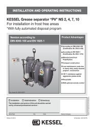
<strong>KESSEL</strong> - <strong>Aqualift</strong> <strong>Hebeanlage</strong> <strong>bis</strong> <strong>Baujahr</strong> <strong>12</strong>/<strong>95</strong><br />
Installation Inbetriebnahme Einweisung<br />
der Anlage wurde durchgeführt von Ihrem Fachbetrieb:<br />
Name/Unterschrift Datum Ort Stempel Fachbetrieb<br />
Produktvorteile<br />
D Die komplette Schmutzwasserhebeanlage<br />
mit Rückschlagklappe<br />
GB Complete Wastewater lifting<br />
System with backflow Preventer<br />
F Poste complet de relevage<br />
des eaux usées avec clapet antiretour<br />
Änderungsstand: 11/2009-HG<br />
Sachnummer: 099-143<br />
Techn. Änderungen vorbehalten
Inhaltsverzeichnis<br />
Allgemeines .......................................................................................................... Seite 3/4<br />
Einbau / Installation / Installation .......................................................................................................... Seite 5-9<br />
Einbaubeispiele / Examples of installation<br />
Modele d’installation .......................................................................................................... Seite 10<br />
Einbaumuster / Model of installation<br />
Modèle d’installation .......................................................................................................... Seite 11<br />
Einbautips / Models of installation<br />
Modèles d’installation .......................................................................................................... Seite <strong>12</strong>/13<br />
Technische Daten / Technical data<br />
Donnèes techniques .......................................................................................................... Seite 14<br />
Leistungstabelle / Table of performance<br />
Tableau de rendement .......................................................................................................... Seite 15<br />
Abmessungen (Pumpe) / Dimensions (Pump)<br />
Dimensions (Pompe) .......................................................................................................... Seite 15<br />
Achtung! / Attention! / Attention! .......................................................................................................... Seite 16<br />
Gewährleistung / Warranty / Garantie .......................................................................................................... Seite 17-19<br />
2
D Die komplette Schmutzwasserhebeanlage<br />
mit Rückschlagklappe<br />
Durch den Einsatz von dauerresistenten,<br />
hochwertigen und hochschlagfesten Kunststoffen<br />
haben wir eine Schmutzwasserhebeanlage<br />
geschaffen, die in ihrer Leistung<br />
zum benötigten Platzaufwand unübertroffen<br />
ist. Die hierzu verwendeten Stähle sind<br />
absolut korrosionsfrei, die Kunststoffe sind<br />
gegen haushaltsübliche Laugen und Säuren<br />
beständig, ebenso gegen Kälte und<br />
Heißwasser (<strong>bis</strong> <strong>95</strong>° C). Leistungstabelle<br />
der Pumpe beachten (siehe letzte Seite).<br />
Als weitere Punkte neben dem geringen<br />
Gewicht sind die äußerst niedrige Einbauhöhe<br />
und die einfache Montage der<br />
UNIVA-<strong>Aqualift</strong>-<strong>Hebeanlage</strong> zu nennen.<br />
Der UNIVA-<strong>Aqualift</strong> ermöglicht durch wahlweises<br />
Anbringen von Zulaufstutzen DN 50-<br />
70 oder 100 den Anschluß von Ferneinläufen<br />
und gewährleistet somit die sichere Entsorgung<br />
von Duschen, Waschmaschinen<br />
usw., sowie von Regenwasser aus tiefgele-<br />
Allgemeines<br />
genen Räumen oder Kellerabgängen. Außerdem<br />
ist der Anschluß für Gebäude- und<br />
Grundstücksentwässerung über Drainagerohr-Zuleitungen<br />
möglich. Bei Verwendung<br />
von Aufsatzstücken kann ein stufenlos vertiefter<br />
Einbau erreicht werden. Grundkörper<br />
und Aufsatzstücke sind dicht miteinander<br />
zu verbinden (z. B. mit Silikon, oder Tangit).<br />
GB Complete Wastewater lifting<br />
System with backflow Preventer<br />
By the use of very persistent and impact resistant<br />
plastics of high-quality (slight by resistant<br />
to alkaline and acid solutions, to cold<br />
and hot water up to <strong>95</strong>° C) as well as stainless<br />
steels, we have created a wastewater<br />
lifting system which is unexcelled in its performance<br />
and does not require much space.<br />
As other advantages, we must hold up lightness,<br />
as well as the low height of installation<br />
and the easy setting of the wastewater lifting<br />
system UNIVA-<strong>Aqualift</strong>. Through the possi-<br />
3<br />
bility of adapting inlet nozzles Ø 50, 70, 100,<br />
the UNIVA-<strong>Aqualift</strong> system enables the<br />
branch of arriving water mains thus guaranteeing<br />
the disposal of water coming from<br />
showers, washing maschines etc., as well<br />
as rainwater from underground rooms or<br />
outdoor basement stairs. Besides the<br />
branch for a house-drainage system can be<br />
connected by supply drainage pipes.<br />
Through employment of frames (size 3, ref.<br />
32 500), you can obtain a deeper setting, as<br />
well as a larger capacity of the system, at all<br />
the same time the frames enable an installation<br />
at a frost free level.<br />
F Poste complet de relevage des eaux<br />
usées avec clapet antiretour<br />
Grâce à des matières plastiques très performantes<br />
(résistant facilement aux éléments<br />
caustiques et aux acides, résistant également<br />
aux variations de température jusquʼà<br />
<strong>95</strong>° C) et avec très haute résistance aux
chocs, grâce aussi aux aciers inoxydables,<br />
nous avons créé un poste de relevage des<br />
eaux usées qui par son faible encombrement<br />
ne coûte rien point de vue place.<br />
En tant quʼautres points avantageux, il faut<br />
citer la légèreté, ainsi que la faible hauteur<br />
dʼinstallation intérieure et la facilité de montage<br />
du poste de relevage UNIVA-<strong>Aqualift</strong>.<br />
Allgemeines<br />
Grâce à la possibilité dʼadapter des raccords<br />
dʼalimentation Ø 50, 70, 100, le poste<br />
UNIVA-<strong>Aqualift</strong> perment le branchement de<br />
conduits dʼarrivée et facilité ainsi Iʼévacuation<br />
de Iʼeau des douches, machines à laver<br />
etc., ainsi que des eaux pluviales depuis les<br />
pièces de sous-sol ou sorties de cave. De<br />
plus, le branchement pour Iʼextraction de<br />
4<br />
Iʼeau des bâtiments et terrains est possible<br />
sur uns amenée de tuyau de drainage. En<br />
utilisant des rehausses (standard 3 réf.<br />
32500) on peut atteindre un approfondissement<br />
de Iʼinstallation ainsi quʼune plus grande<br />
capacité du poste; en même temps, ces<br />
rehausses permettent une installation à un<br />
niveau épargné par le gel.
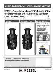
Einbau · Installation · Installation<br />
Einhängeflansch der Pumpe<br />
und des Gehäuses<br />
Suspension flange of the pump<br />
and housing<br />
Bride de suspension de la pompe<br />
du boîtier<br />
<strong>Hebeanlage</strong> von oben, ohne Gitterrost und Abdeckplatte dargestellt.<br />
Lifting unit shown from above without grate and locking cover plate.<br />
Poste de relevage vu de haut présenté sans grille et sans couvercle.<br />
5<br />
Stufenlose Einbautiefe durch<br />
beliebiges Absägen der UNIVA-<br />
Aufsatzstücke (Best.-Nr. 32500)<br />
Perfect equalizing by sawing the UNIVAframes<br />
off (ref. 32500)<br />
Mise à niveau parfaite par découpage des<br />
rehausses UNIVA (réf. 32500)<br />
Um Schmutzablagerungen zu vermeiden,<br />
sollte beim Einbau des Reduzierstückes darauf geachtet werden,<br />
daß die gerade Fläche unten liegt.<br />
To avoid deposits of dirt, pay attention, by setting the reducer,<br />
that it is situated on the flat part.<br />
Afin dʼéviter les dépôts de saletés, il faut faire attention,<br />
en montant la pièce de réduction, que celle-ci repose sur al partie plate.<br />
5 Meter mit Schukostecker für Anschluß<br />
an Steckdose 230 V ~ 50 Hz. Absicherung mind. 6 Amp. träge<br />
Wire of 5 m with plug. Power 230 V ~ 50 Hz.<br />
Protection of min. 6 Amp. inert<br />
Câble de 5 m avec prise de courant pour branchement<br />
au secteur 230 V ~ 50 Hz.<br />
Protection au moins de 6 Amp. inerte
D<br />
1. Vor dem Einbau der UNIVA-<strong>Aqualift</strong>-<br />
<strong>Hebeanlage</strong> sind alle Teile auf äußere<br />
Transportschäden zu überprüfen.<br />
2. Reduzierstück (2) auf gewünschten<br />
Druckleitungsanschluß DN 50 oder DN 40<br />
absägen. Reduzierstück auf Ablaufstutzen<br />
kleben (PVC-Kleber). Druckleitung (DIN<br />
8063) anschließen (Verbindung muß Iängskraftschlüssig<br />
erfolgen).<br />
3. Kabelaustritt (7) am Gehäuse (1) oder<br />
Aufsatzstück Best.-Nr. 32500 wahlweise<br />
nach »Roter Montageanleitung für Zu- und<br />
Ablaufstutzen« anbringen und beigefügten<br />
Zulaufstutzen (7) DN 50 einschrauben<br />
(siehe Bild 3). Ferneinläufe von Duschen,<br />
Waschmaschinen oder Kellerabläufen festlegen<br />
und wahlweise Zulaufstutzen (13)<br />
rechts, links oder mittig DN 50-70 oder 100,<br />
anbringen.<br />
4. Gehäuse (1) nach Anschluß sämtlicher<br />
Rohrleitungen im Betonbett eingießen.<br />
Zum evtl. Ausgleich des Kellerbodens ist<br />
ein Aufsatzstück Best.-Nr. 32500 zu ver-<br />
Einbau · Installation · Installation<br />
wenden, durch beliebiges Absägen des<br />
Aufsatzstückes kann jede Einbautiefe<br />
stufenlos erreicht werden. Grundkörper<br />
und Aufsatzstücke sind dicht miteinander<br />
zu verbinden (z.B. mit Silikon oder Tangit).<br />
5. Aus- und Einbau der Pumpe:<br />
a) Ausbau:<br />
Durch Lösen der beiden Sechskantmuttern<br />
(10) kann die Pumpe (4) komplett mit Rückschlagklappe<br />
(8) und Rollring (3) aus dem<br />
Gehäuse (1) genommen werden. Dadurch<br />
ist ein ungehinderter Zugang zum Reinigen<br />
der Druckleitung möglich. Durch Abziehen<br />
der kompletten Rückschlaghalterung (8)<br />
können Pumpe und Klappe leicht gereinigt<br />
werden.<br />
b) Einbau:<br />
Vor Einbau sämtliche Dichtflächen reinigen,<br />
Rollring (3) (bei Bedarf neuen Rollring DN<br />
100) in die dafür vorgesehene Ringnut der<br />
Pumpe (4) einlegen. Rückschlaghalterung<br />
(8) fest auf Pumpenflansch aufdrücken.<br />
Komplette Pumpe auf die zwei Schrauben<br />
(9) im Gehäuse (1) aufstecken, an die Ge-<br />
6<br />
häusewand schieben und nach unten in den<br />
Einhängeflansch (14) einrasten lassen. Ein<br />
leichtes Schrägstellen der Pumpe erleichtert<br />
das Einrasten in den Einhängeflansch<br />
(14). Anschließend mit den beiden Sechskantmuttern<br />
(10) Pumpe und Gehäuse verschrauben.<br />
Kabel mit Stecker (6) durch Kabelrohr<br />
(siehe Bild 3) mittels eines Zugdrahtes<br />
einziehen und an Steckdose anschließen.<br />
Behälter mit Wasser auffüllen<br />
und Schwimmerschalter (5) auf Funktion<br />
überprüfen. Abdeckplatte (<strong>12</strong>) und Gitterrost<br />
(11) einlegen; es ist darauf zu achten,<br />
daß die Abdeckplatte (<strong>12</strong>) über der Pumpe<br />
liegt.<br />
Besondere Bestimmungen des Instituts<br />
für Bautechnik, Berlin:<br />
Die Kellerentwässerungspumpen dürfen<br />
zum Heben von leicht verschmutztem Abwasser<br />
nicht jedoch von solchen aus Klosett-<br />
und Urinanlagen, in der Grundstücksentwässerung<br />
gemäß den Bestimmungen<br />
der Norm DIN 1986 verwendet werden.<br />
Die Druckrohrleitungen müssen über die
örtlich festgelegten Rückstauebenen hochgeführt<br />
werden. Der Anschluß an den<br />
Druckstutzen muß Iängskraftschlüssig erfolgen.<br />
Bei Anlagen, die innerhalb von Gebäuden<br />
verwendet werden, sind die Bestimmungen<br />
der Norm DIN 4109 - Schallschutz im Hochbau<br />
- zu beachten.<br />
Wartung:<br />
Die Pumpe mindestens zweimal jährlich<br />
äußerlich reinigen und die Einlauföffnungen<br />
säubern, bzw. mit klarem Wasser durchspülen.<br />
Die Pumpe niemals selber öffnen<br />
(nur durch Fachmann), da bei unsachgemäßem<br />
Eingriff die Abdichtung der Pumpe<br />
beschädigt werden und Öl in das Abwasser<br />
gelangen könnte.<br />
Entsprechend den Vorschriften für abwassertechnische<br />
Anlagen dürfen mit der<br />
UNIVA-<strong>Aqualift</strong>-<strong>Hebeanlage</strong> keine Fäkalien<br />
und keine brennbaren oder explosiven<br />
FIüssigkeiten gefördert werden.<br />
Vorsicht: Benutzung in Schwimmbecken<br />
und Gartenteichen und deren Schutzbe-<br />
Einbau · Installation · Installation<br />
reich nur zulässig, wenn diese nach VDE<br />
0100 § 49d errichtet sind. Bitte fragen Sie<br />
Ihren Elektrofachmann.<br />
GB<br />
1. Before installation of the wastewater<br />
lifting system UNIVA-<strong>Aqualift</strong>, please<br />
check up the pieces with regard to external<br />
transport damages.<br />
2. Reducer(2) to be sawn off at DN 50 or 40<br />
according to the reguired branch of pressure<br />
main. Place sealing ring (3) DN 100 into<br />
the slot, grease and fit to the branch piece<br />
of the housing. Pay attention that it is situated<br />
on the flat part (see drawing 1). If it is<br />
sticked together with PVC glue, no sealing<br />
ring (3) is needed.<br />
3. Fix the outlet nozzle (7) of the wire to the<br />
housing (1) or the frame ref. 32500 according<br />
to the „red instructions for installation of<br />
the inlet of outlet nozzle“ and screw in the<br />
inlet nozzle (7) DN 50 (drawing 3). Fix the<br />
arriving mains of showers, washing machi-<br />
7<br />
nes or basement sewers and connect inlet<br />
nozzles (13) on the right, on the left or in the<br />
middle DN 50, 70 or 100.<br />
4. After branch of all pipes, place housing<br />
(1) into a concrete bed. In order to achieve<br />
continuous adjustment to floor level,<br />
use frames ref. 32500; to have a perfect<br />
equalisation saw the frames off. A seal of<br />
Terroson inserted between the housing and<br />
the frame enables, if requested a watertight<br />
closure.<br />
5. Removal and setting of the pump:<br />
a) Removal:<br />
By unscrewing both hexagon bolts (10), the<br />
pump (4) can be completely taken off from<br />
the housing (1) with backflow preventer (8)<br />
and joint ring (3). By this it is possible to<br />
clean the pressure pipe. Taking off the complete<br />
backflow preventer unit, the pump and<br />
the preventer can be easily cleaned.<br />
b) Setting:<br />
Before setting clean all joint surfaces, insert<br />
sealing ring (3) (if necessary new joint DN<br />
100) into the slot of the pump (4), fit the
ackflow preventer unit (8) into the flange of<br />
the pump. Fix the complete pump in the<br />
housing (1) with both screws (9), insert<br />
along the inside surface of housing and<br />
place on the suspension flange (14). A slight<br />
tilt of the pump facilitates its installation into<br />
the suspension flange (14). At last, fix the<br />
pump to the housing with both hexagon<br />
bolts (10). Insert the electrical cable and the<br />
plug through the blank pipe (drawing 3) with<br />
a wire and branch into the stocket. Fill up the<br />
housing with water and test the automatic<br />
float (5). Put on the locking cover plate (<strong>12</strong>)<br />
and the grate (11); it is important that the<br />
cover plate is situated over the pump.<br />
Particular prescriptions of the Institut<br />
for Technical Setting, Berlin:<br />
Basement sewers can be used in a housedrainage<br />
system to lift wastewater which is<br />
not very dirty, however, not coming from sanitary<br />
installation (WC), according to the<br />
prescriptions of the effluent standard DIN<br />
1986.<br />
Pressure pipes must always be lead over<br />
Einbau · Installation · Installation<br />
local backwater level. The link to the pressure<br />
pipe must be made with an elbow of<br />
45°. For installation in buildings, refer to the<br />
effluent standard DIN 4109 - protection<br />
against noise in surface engineering.<br />
Maintenance:<br />
Clean the pump and wash the infall openings<br />
with clear water at least twice a year.<br />
Never open the pump by yourself (only by<br />
an expert), because in the event of wrong<br />
handling, the sealing of the pump can be damaged<br />
and oil could get into the wastewater.<br />
According to the prescriptions for installation<br />
of drainage systems, no fecal substances<br />
and no inflammable or explosive liquids<br />
must be extracted by the wastewater<br />
lifting system UNIVA-<strong>Aqualift</strong>.<br />
Attention: To be used for swimming-pool<br />
and garden ponds as well as the protected<br />
area around them, only if they are established<br />
according to VDE 0100 § 49d. Contact<br />
your electrician.<br />
8<br />
F<br />
1. Avant d’installer le poste de relevage<br />
UNIVA-<strong>Aqualift</strong>, contrôler que les pièces<br />
n’ont été endommagées par le transport.<br />
2. Réduction (2) à scier selon le branchement<br />
du tuyau pression souhaité. Placer le<br />
joint (3) dans la rainure, graisser et emboîtier<br />
à Iʼouverture du boîtier. Lors de cette<br />
opération, bien observer que la partie plate<br />
est en bas (voir schéma 1). En collant avec<br />
de la colle PVC, le joint (3) peut être supprimé.<br />
3. Apporter la sortie de câble (7) au boîtier<br />
(1) ou à la rehausse réf. 32500 selon „les instructions<br />
de montage en rouge pour le raccord<br />
dʼentrée ou de sortie“ et visser le raccord<br />
dʼalimentation (7) DN 50 (voir schéma<br />
3). Fixer les conduites dʼarrivée des douches,<br />
machines à laver ou sortie de cave et<br />
les amener aux raccords (13) de droite, de<br />
gauche ou du milieu DN 50, 70 ou 100.<br />
4. Après branchement de Iʼensemble de la<br />
tuyauterie, placer le boîtier (1) dans un<br />
moule de béton. Pour une éventuelle mise
à niveau au sol de la cave, utiliser une rehausse<br />
réf. 32500; le découpage de la<br />
rehausse perment une mise à niveau<br />
parfaite. Un joint en Terroson placé entre le<br />
boîtier et la rehausse perment, si cela est<br />
souhaité, un assemblage étanche.<br />
5. Démontage et montage de la pompe:<br />
a) Démontage:<br />
En desserrant les deux écrous (10) on peut<br />
sortir complètement la pompe (4) du boîtier<br />
avec clapet anti-retour (8) et joint (3). De<br />
cette façon, il est alors possible de nettoyer<br />
le tuyau pression. En retirant le système<br />
complet anti-retour, on peut ainsi nettoyer la<br />
pompe et le clapet.<br />
b) Montage:<br />
Avant le montage, nettoyer Iʼensemble des<br />
surfaces de jonction, placer le joint (3) (si<br />
besoin nouveau joint DN 100) dans la rainure<br />
de la pompe (4), emboîter le système<br />
anti-retour (8) sur la bride de la pompe.<br />
Fixer la pompe complette dans le boîter (1)<br />
avec les deux vis (9), glisser vers le bas le<br />
long de la paroi du boîtier et laisser reposer<br />
Einbau · Installation · Installation<br />
sur la bride suspension (14). Une Iégère inclinaison<br />
de la pompe facilite la fixation<br />
dans la bride de suspension. Enfin, fixer la<br />
pompe au boîtier avec les deux écours (10).<br />
Glisser le câble et la prise de courant (6)<br />
dans la gaine (voir schéma 3) à Iʼaide dʼun<br />
fil de fer et brancher au secteur. Remplir le<br />
boîtier dʼeau et tester le flotteur automatique<br />
(5). Placer le couvercle (<strong>12</strong>) et la grille (11);<br />
il est important que le couvercle (<strong>12</strong>) se<br />
situe au-dessus de la pompe.<br />
Prescriptions particulières de I’lnstitut<br />
de Montages Techniques, Berlin:<br />
Les pompes vide-cave peuvent être utilisées<br />
dans le drainage domestique pour le<br />
relevage des eaux peu sales et non des<br />
eaux provenant des installations sanitaires<br />
(WC), selon les prescriptions de la norme<br />
DIN 1986. Les tuyaux de pression doivent<br />
être conduits en permanence au-dessus du<br />
niveau des remous. Le branchement au<br />
raccord de pression doit arriver en angle de<br />
45°.<br />
Pour les installations dans les bâtiments, il<br />
9<br />
faut seréférer aux prescriptions de la norme<br />
DIN 4109 - protection contre le bruit dans<br />
les constructions en surface.<br />
Entretien:<br />
Nettoyer la pompe extérieurement au moins<br />
deux fois par an et laver les ouvertures dʼarrivée<br />
à Iʼeau claire. Ne jamais ouvrir la<br />
pompe soi-même (seul un spécialiste peut<br />
le faire), car en cas de mauvaise manipulation,<br />
Iʼétanchéité de la pompe peut être<br />
détériorée et de Iʼhuile pourrait arriver dans<br />
les eaux usées.<br />
Selon les inducations pour les installations<br />
dʼévacuations dʼeau, aucune vidange et<br />
aucun liquide inflammable ou explosif ne<br />
doivent être extraits par le poste de relevage<br />
UNIVA-<strong>Aqualift</strong>.<br />
Attention: Lʼutilisation dans les piscines et<br />
réserves de jardin et dans leur zone de protection<br />
nʼest permise que si celles-ci sont<br />
aménagées selon VDE 0100 § 49d. Renseignez-vous<br />
auprès de votre électricien<br />
agréé.
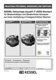
Einbaubeispiele · Examples of installation · Modele d’installation<br />
Ferneinläufe ins Gehäuse oder Aufsatzstück DN 100 - 70 oder 50<br />
rechts, links oder mittig möglich.<br />
Infall pipes into the housing or into the frame DN 100, 70 or 50<br />
possible on the right, on the left or in the middle.<br />
Conduits dʼarrivée dans le boîtier ou la rehausse<br />
DN 100, 70 ou 50 possible à droite, gauche ou au millieu.<br />
Achtung für 87° HT-Bogen<br />
müssen 2 x 45° HT-Bogen<br />
eingesetzt werden.<br />
Important: use two bends of<br />
45° instead of one bend of 87°.<br />
Attention: utiliser deux coudes<br />
de 45° au lieu dʼun de 87°.<br />
an<br />
on<br />
ouvert<br />
aus<br />
off<br />
fermé<br />
Kabelanschluß mit Zulaufstutzen DN 50 Nr. 39005<br />
Connection with inlet nozzle DN 50 ref. 39005<br />
Passage avec racord DN 50 réf. 39005<br />
D<br />
Beispiel einer UNIVA-<strong>Aqualift</strong>-<strong>Hebeanlage</strong> mit<br />
Aufsatzstück Größe 3. Einbaumöglichkeiten<br />
zur Installation des Elektrokabels und Schukostecker<br />
mit verschiedenen Kabelrohren.<br />
Rohrverlegung für Kabel, Kabellänge: 5 m, Steckdose: 230 V ~ 50 Hz<br />
Insertion of the cable through blank pipes length of cable: 5 m, power: 230 V ~ 50 Hz<br />
Passage du câble sous gaine longueur du câble: 5 m, moteur: 230 V ~ 50 Hz<br />
HT-Rohr<br />
HT-blank pipe<br />
gaine HT<br />
GB<br />
Lifting system UNIVA-<strong>Aqualift</strong> with frame<br />
size 3. Possibility to insert the cable and the<br />
plug through different blank pipes.<br />
Panzerrohr<br />
Kabelanschluß mit NH-Verschraubung<br />
und Gegenmutter<br />
Innen Ø 48,7 mm<br />
Typ 48<br />
Stiffblank pipe connection with<br />
NH screwed and lock nuted link<br />
Ø inside 48.7 mm<br />
type 48<br />
Gaine rigide passage avec<br />
fermeture à vis et contre-écrou<br />
NH<br />
Ø int. 48,7 mm<br />
type 48<br />
10<br />
Wellrohr<br />
Kabelanschluß mit BIMO-Verschraubung<br />
und Gegenmutter<br />
Innen Ø 47,7 mm<br />
Typ 48<br />
Semistift blank-pipe connection<br />
with BIMO screwed and lock<br />
nuted link Ø inside 47.7 mm<br />
type 48<br />
Gaine semi-rigide<br />
passage avec fermeture<br />
à vis et contre-écrou<br />
BIMO Ø int. 47,7 mm<br />
type 48<br />
F<br />
Exemple de poste de relevage UNIVA-<br />
<strong>Aqualift</strong> avec rehausse standard 3.<br />
Possibilité dʼutiliser des gaines différentes<br />
pour le passage du cable et de la prise.
Einbaumuster · Model of installation · Modèle d’installation<br />
D<br />
Einbau- und Anschlußmöglichkeiten an<br />
UNIVA-<strong>Aqualift</strong>-<strong>Hebeanlage</strong> mit höhenverstellbarem<br />
Aufsatzstück.<br />
GB<br />
Possibilities of installation and branch to the<br />
pump UNIVA-<strong>Aqualift</strong> with adjustable frame.<br />
11<br />
F<br />
Possibilité dʼinstallation et de branchement<br />
à la pompe UNIVA-<strong>Aqualift</strong> avec adaptation<br />
en hauteur des rehausses.
Einbautips · Models of installation · Modèles d’installation<br />
D<br />
Ein leichtes Schrägstellen der Pumpe<br />
bzw. des Notverschlusses erleichtert das<br />
Einrasten in den Einhängeflansch (G). Beim<br />
Einbau des Kellerablaufes ist darauf zu achten,<br />
daß die Wand im Bereich der schwarzen<br />
Pfeile nicht verzogen wird.<br />
Der Zulaufstutzen bietet die Möglichkeit,<br />
die <strong>Hebeanlage</strong> oder das Aufsatzstück<br />
nachträglich in jeder Richtung aufzubohren,<br />
um Ferneinläufe zuzuführen.<br />
<br />
GB<br />
A slight tilt of the pump or of the security<br />
lever makes easier the installation into the<br />
suspension flange (G). By installing the basement<br />
outlet, it is important not to bend the<br />
wall in the area shown by the black pointer.<br />
The inlet nozzle offers the possibility of<br />
boring later in all directions through the lifting<br />
unit or the frames in order the lead arriving<br />
mains.<br />
<strong>12</strong><br />
F<br />
Une Iégère inclinaison de la pompe ou de<br />
la fermeture de sécurité facilite Iʼinstallation<br />
dans la bride de suspension (G). En montant<br />
le système dʼevacuation de sous-sol, il est<br />
important de faire attention à ne pas coucher<br />
la paroi montrée par la flèche hove-joint.<br />
Le raccord dʼalimentation offre la possibilité<br />
de percer ultérieurement dans toutes les directions<br />
le poste de relevage ou les rehausses<br />
afin dʼamener des conduites dʼarrivée.
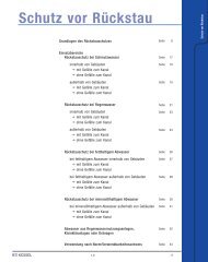
Einbautips · Models of installation · Modèles d’installation<br />
Gehäusedeckel<br />
Cover plate of the housing<br />
Couvercle du boîtier<br />
Dichtring DN 100<br />
Sealing ring DN 100<br />
Joint DN 100<br />
Klappenhalterung mit<br />
Rückschlagklappe<br />
Backflow preventer and support<br />
Clapet anti-retour et support<br />
Kondensator<br />
Condenser<br />
Condensateur<br />
Ansaugkorb<br />
Suction basket<br />
Panier dʼaspiration<br />
5 m-Anschlußklappe<br />
mit Schukostecker HO7RN<br />
Wire with plug HO7RN length 5 m<br />
Câble électrique avec prise<br />
de courant HO7RN longueur 5 m<br />
13<br />
Ansaugdeckel<br />
Suction cover plate<br />
Couvercle dʼaspiration<br />
Motorschutzschalter<br />
Security swith of the<br />
motor<br />
Interrupteur de sécurité<br />
du moteur<br />
Stator<br />
Stator<br />
Stator<br />
Schwimmerschalter<br />
für automatische<br />
Niveauschaltung<br />
Automaticfloat for<br />
automatic levelling<br />
Flotteur automatique<br />
Flügelrad<br />
Ventilator<br />
Ventilateur
Technische Daten · Technical data · Données techniques<br />
Typ Leistung P1*) Drehzahl Stromart Betriebsspannung<br />
Type Performance Revolutions Power Voltage<br />
Type Rendement Nombre de Tours Courant Tension<br />
Wechselstrom 50 Hz<br />
<strong>Aqualift</strong> 0.5 kW 2850 U/min. Alternating courant 50 Hz 230 Volt<br />
Courant alternatif 50 Hz<br />
Nennstrom Sicherung Kabellänge Steckvorrichtung Motorschutz<br />
Nominal Power Security Length of wire Plugging device Protection of Motor<br />
Courant Nominal Sécurité Longueur de câble Dispositif de Branchement Protection du Moteur<br />
6 Amp. träge 5 m Schuko 2-pol. eingebaut<br />
2,4 Amp. 6 Amp. inert 10 m **) Bipolar plug mounted<br />
6 Amp. inerte Fiche bipolaire montée<br />
D<br />
**) P1 = die dem Netz entnommene<br />
Wirkleistung<br />
**) Im Freien mit 10 m verwenden<br />
GB<br />
**) P1 = active power<br />
**) use a wire of 10 m outdoors<br />
14<br />
F<br />
**) P1 = dépit de pompage pris au réseau<br />
**) En air libre utiliser un câble de 10 m
Leistungstabelle · Table of performance · Tableau de rendement<br />
Typ Motorleistung Förderstrom Förderhöhe (m) • Pumping level (m) • Hauteur de relevage (m)<br />
Type Performance Delivery Q<br />
Type Rendement Débit 1 2 3 4 5 6 7 8 9 10<br />
<strong>Aqualift</strong><br />
0.5<br />
P1/kW<br />
l/min<br />
m<br />
190 170 140 110 85 50 stand.<br />
3/h 11.4 10.2 8.4 6.6 5.1 3 –<br />
D<br />
Tauchtiefe 10 m<br />
Dauertemperatur bei Schmutzwasserförderung<br />
40° C.<br />
AB-Betrieb 50% ED 30 min.<br />
GB<br />
Depth of immision 10 m<br />
Continued temperature in case of extraction<br />
of wastewater 40° C.<br />
AB-operation 50% outfall length 30 min.<br />
F<br />
Profondeur dʼimmersion 10 m<br />
Température continue par pompage des<br />
eaux usées 40° C.<br />
Durée dʼecoulement 30 min.<br />
Abmessungen (Pumpe) · Dimensions (Pump) · Dimensions (Pompe)<br />
Gewicht Höhe Größter Durchmesser Breite Tiefe<br />
Weight Height Largest calibre Breadth Depth<br />
Poids Hauteur Plus grand calibre Largeur Profondeur<br />
185 mm ohne Schwimmer 160 mm ohne Schwimmer 165 mm ohne Rückstauklappe<br />
6.1 kg 215 mm 185 mm without float 160 mm without float 165 mm without backflow preventer<br />
185 mm sans flotteur 160 mm sans flotteur 165 mm sans clapet anti-retour<br />
15
D<br />
Achtung!<br />
Tauchmotorpumpen enthalten zur Schmierung<br />
und Kühlung Öl, das bei Beschädigung<br />
der Pumpe austreten und das Fördermedium<br />
verunreinigen kann! Bevor Sie Ihre<br />
UNIVA-<strong>Aqualift</strong>-Tauchpumpe in Betrieb<br />
nehmen, lassen Sie fachmännisch prüfen,<br />
ob eine der angeführten elektrischen<br />
Schutzmaßnahmen vorhanden ist: Erdung,<br />
Nullung, Trenntrafe oder Fehlerstromschutzschaltung;<br />
diese müssen den örtlichen<br />
EVU-Vorschriften entsprechen und<br />
einwandfrei funktionieren. (EVU = Energie-<br />
Versorgungsunternehmen)<br />
Die elektrische Steckvorrichtung ist vor<br />
Nässe zu schützen! Bei Überschwemmungsgefahr<br />
die Steckvorrichtung im überflutungssicheren<br />
Bereich montieren. Geprüfte<br />
Sicherheit nach VDE-Vorschriften<br />
gemäß Maschinenschutzgesetz der Landesgewerbeanstalt<br />
Nürnberg und der ETVA<br />
Wien nach ÖVE-Vorschriften. Allgemeine<br />
bauaufsichtliche Zulassung Nr. Z-53.3-310<br />
des Instituts für Bautechnik, Berlin<br />
Achtung! · Attention! · Attention!<br />
GB<br />
Attention!<br />
The motors of submersible pumps contain<br />
lubricating and cooling oil which may spill<br />
over and clog the medium of extraction in<br />
case of damage of the pump! Before you<br />
use your submersible pump UNIVA-<strong>Aqualift</strong>,<br />
let a specialist control if one of the following<br />
protective measures has been taken:<br />
earthing, neutral point, transformer with a<br />
circuit breaker of security switch for the case<br />
of power failure, they must correspond to<br />
the prescriptions of the local EVU and perfectly<br />
work. (EVU = power station)<br />
Keep the plug in a dry place in case of<br />
danger of inundation, put the plugging<br />
device in a protected place.<br />
Tested security according to VDE instructions,<br />
law for the protection of machines<br />
of the National Industrial Institution<br />
at Nuremberg, and ETVA Vienna according<br />
to ÖVE instructions.<br />
Test certificate Z-53.3-310<br />
of the Institute for Technical Setting, Berlin.<br />
16<br />
F<br />
Attention!<br />
Les moteurs de pompes submersibles contiennent<br />
de Iʼhuile lubrifiante et de refroidissement<br />
qui peut, en cas de détérioration de la<br />
pompe, se répandre et endrasser le médium<br />
dʼextraction! Avant de mettre en marche votre<br />
pompe submersible UNIVA-<strong>Aqualift</strong>, faites<br />
contrôler par un spécialiste que les mesures<br />
de protection données sont bien existantes:<br />
mise à la terre, neutre, transformateur de sécurité<br />
ou interrupteur de sécurité en cas de<br />
panne de courant; ceux-ci doivent répondre<br />
aux indications de la EVU locale et parfaitement<br />
fonctionner. (EVU = centrale électrique)<br />
Protéger la prise de courant de l’humidité!<br />
En cas de danger d’inondation, monter la<br />
prise de courant dans un milieu protégé.<br />
Sécurité testée d’après les instructions de<br />
la loi sur la protection des machines de I’lnstitution<br />
Industrielle à Nuremberg et d’après<br />
les instructions ÖVE de I’ETVA viennois.<br />
Numero d’agrement Z-53.3-310 de<br />
Iʼlnstitut pour les Techniques de Montage,<br />
Berlin.
1. Ist eine Lieferung oder Leistung mangelhaft,<br />
so hat <strong>KESSEL</strong> nach Ihrer Wahl den<br />
Mangel durch Nachbesserung zu beseitigen<br />
oder eine mangelfreie Sache zu liefern.<br />
Schlägt die Nachbesserung zweimal fehl oder<br />
ist sie wirtschaftlich nicht vertretbar, so hat der<br />
Käufer/Auftraggeber das Recht, vom Vertrag<br />
zurückzutreten oder seine Zahlungspflicht<br />
entsprechend zu mindern. Die Feststellung<br />
von offensichtlichen Mängeln muss unverzüglich,<br />
bei nicht erkennbaren oder verdeckten<br />
Mängeln unverzüglich nach ihrer Erkennbarkeit<br />
schriftlich mitgeteilt werden. Für Nachbesserungen<br />
und Nachlieferungen haftet<br />
17<br />
Gewährleistung<br />
<strong>KESSEL</strong> in gleichem Umfang wie für den ursprünglichen<br />
Vertragsgegenstand. Für Neulieferungen<br />
beginnt die Gewährleistungsfrist<br />
neu zu laufen, jedoch nur im Umfang der Neulieferung.<br />
Es wird nur für neu hergestellte Sachen eine<br />
Gewährleistung übernommen.<br />
Die Gewährleistungsfrist beträgt 24 Monate<br />
ab Auslieferung an unseren Vertragspartner.<br />
§§ 377.378 HGB finden weiterhin Anwendung.<br />
Über die gesetzliche Regelung hinaus erhöht<br />
die <strong>KESSEL</strong> AG die Gewährleistungsfrist für<br />
Leichtflüssigkeitsabscheider, Fettabscheider,<br />
Schächte, Kleinkläranlagen und Regenwas-<br />
serzisternen auf 20 Jahre bezüglich Behälter.<br />
Dies bezieht sich auf die Dichtheit, Gebrauchstauglichkeit<br />
und statische Sicherheit.<br />
Voraussetzung hierfür ist eine fachmännische<br />
Montage sowie ein bestimmungsgemäßer Betrieb<br />
entsprechend den aktuell gültigen Einbau-<br />
und Bedienungsanleitungen und den gültigen<br />
Normen.<br />
2. <strong>KESSEL</strong> stellt ausdrücklich klar, dass Verschleiß<br />
kein Mangel ist. Gleiches gilt für Fehler,<br />
die aufgrund mangelhafter Wartung auftreten.<br />
Stand 10.11.2009
1. In the case that a <strong>KESSEL</strong> product is defective,<br />
<strong>KESSEL</strong> has the option of repairing<br />
or replacing the product. If the product remains<br />
defective after the second attempt to<br />
repair or replace the product or it is economically<br />
unfeasible to repair or replace the<br />
product, the customer has the right to cancel<br />
the order / contract or reduce payment<br />
accordingly. <strong>KESSEL</strong> must be notified immediately<br />
in writing of defects in a product.<br />
In the case that the defect is not visible or<br />
difficult to detect, <strong>KESSEL</strong> must be notified<br />
immediately in writing of the defect as soon<br />
as it is discovered. If the product is repaired<br />
or replaced, the newly repaired or replaced<br />
product shall receive a new warranty identical<br />
to that which the original (defective)<br />
Warranty<br />
product was granted. The term defective<br />
product refers only to the product or part<br />
needing repair or replacement and not necessarily<br />
to the entire product or unit.<br />
<strong>KESSEL</strong> products are warranted for a period<br />
of 24 month. This warranty period begins<br />
on the day the product is shipped form<br />
<strong>KESSEL</strong> to its customer. The warranty only<br />
applies to newly manufactured products.<br />
Additional information can be found in section<br />
377 and 378 of the HGB.<br />
In addition to the standard warranty,<br />
<strong>KESSEL</strong> offers an additional 20 year warranty<br />
on the polymer bodies of class I / II fuel<br />
separators, grease separators, inspection<br />
chambers, wastewater treatment systems<br />
and rainwater storage tanks. This addition-<br />
18<br />
al warranty applies to the watertightness,<br />
usability and structural soundness of the<br />
product.<br />
A requirement of this additional warranty is<br />
that the product is properly installed and operated<br />
in accordance with the valid installation<br />
and userʼs manual as well as the corresponding<br />
norms / regulations.<br />
2. Wear and tear on a product will not be<br />
considered a defect. Problems with products<br />
resulting from improper installation,<br />
handling or maintenance will also be considered<br />
a defect.<br />
10.11.2009
1. Si une livraison ou une prestation est défectueuse,<br />
<strong>KESSEL</strong> sʼengage, selon votre<br />
choix, à éliminer, par réparation, le manque<br />
constaté ou à livrer un article sans défaut.<br />
Si la réparation échoue par deux fois ou si<br />
elle nʼest pas rentable financièrement, l'acheteur<br />
/ le client a le droit de résilier le contrat<br />
ou de diminuer en conséquence le paiement<br />
dû. La constatation de manques évidents<br />
doit faire lʼobjet dʼun compte-rendu<br />
immédiat ; en cas de manques non reconnaissables<br />
ou cachés, ce compte-rendu<br />
écrit sera envoyé dès que ces manques auront<br />
été constatés. <strong>KESSEL</strong> est responsable<br />
des réparations et livraisons postérieures<br />
dans les mêmes conditions que<br />
19<br />
Garantie<br />
celles de l'objet du contrat originel. En cas<br />
de nouvelles livraisons, le délai de garantie<br />
reprend, mais seulement en ce qui concerne<br />
le volume d'une nouvelle livraison.<br />
Une garantie ne peut être transmise quʼaux<br />
objets nouvellement fabriqués.<br />
La durée de garantie est de 24 mois après<br />
livraison par notre contractant.<br />
Les §§ 377.378 du HGB (code du commerce)<br />
sont applicables ultérieurement.<br />
En se basant sur la réglementation légale,<br />
<strong>KESSEL</strong> AG augmente et accorde un délai<br />
de garantie de 20 ans sʼappliquant au conteneur<br />
pour le décanteur, le dégraisseur, les<br />
puits, les petites stations d'épuration et les<br />
citernes d'eau de pluie. Ceci concerne<br />
l'étanchéité, lʼaptitude à l'emploi et la sécurité<br />
statique.<br />
Il faut, pour cela que le montage ait été effectué<br />
par une entreprise professionnelle et<br />
que lʼexploitation se déroule conformément<br />
aux directives de montage et de service<br />
ainsi quʼaux normes actuellement en vigueur.<br />
2. <strong>KESSEL</strong> rappelle que l'usure n'est pas un<br />
défaut pris en compte par la garantie. Il en<br />
est de même pour les défauts dus à une<br />
maintenance défectueuse.<br />
En date du 10.11.2009
A l l e s f ü r d i e E n t w ä s s e r u n g<br />
❑ Rückstauverschlüsse<br />
❑ <strong>Hebeanlage</strong>n<br />
❑<br />
❑<br />
Abläufe / Rinnen<br />
innerhalb von Gebäuden<br />
Abläufe<br />
außerhalb von Gebäuden<br />
Abscheider<br />
Fettabscheider<br />
Öl-/Benzinabscheider<br />
Stärkeabscheider<br />
Sinkstoffabscheider<br />
Kleinkläranlagen<br />
❑ Schächte<br />
❑<br />
Regenwassernutzanlagen