TAPER-LOCK® BUSHINGS DOUILLES TAPER ... - PTplace.com
TAPER-LOCK® BUSHINGS DOUILLES TAPER ... - PTplace.com
TAPER-LOCK® BUSHINGS DOUILLES TAPER ... - PTplace.com

You also want an ePaper? Increase the reach of your titles
YUMPU automatically turns print PDFs into web optimized ePapers that Google loves.
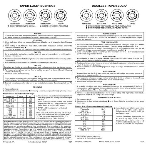
<strong>TAPER</strong>-LOCK ® <strong>BUSHINGS</strong><br />
1008 to 3030 3535 to 6050 7060 to 10085 120100<br />
o INSERT SETSCREWS TO INSTALL INSERT SETSCREWS TO REMOVE<br />
WARNING<br />
To ensure that drive is not unexpectedly started, turn off and lock out or tag power source before<br />
proceeding. Failure to observe these precautions could result in bodily injury.<br />
TO INSTALL<br />
1. Clean shaft, bore of bushing, outside of bushing and hub bore of all oil, paint and dirt. File away<br />
burrs.<br />
2. Insert bushing in hub. Match the hole pattern, not threaded holes (each <strong>com</strong>plete hole will be<br />
threaded on one side only). ▲<br />
3. “LIGHTLY” oil setscrews and thread into those half-threaded holes indicated by o on above diagram.<br />
CAUTION<br />
Do not lubricate the bushing taper, bushing bore, hub taper or the shaft. Doing so could result in<br />
breakage of the product.<br />
4. Position assembly onto shaft allowing for the small axial movement which will occur during tightening<br />
procedure.<br />
5. Alternately torque setscrews to re<strong>com</strong>mended torque setting in chart below.<br />
CAUTION<br />
Do not use worn hex key wrenches. Doing so may result in a loose assembly or may damage screws.<br />
6. To increase gripping force, hammer face of bushing using drift or sleeve. (Do not hit bushing<br />
directly with hammer.)<br />
7. Re-torque screws after hammering.<br />
CAUTION<br />
Where bushing is used with lubricated products such as chain, gear or grid couplings be sure to<br />
seal all pathways (where lubrication could leak) with RTV or similar material.<br />
8. Recheck screw torques after initial run-in, and periodically thereafter. Repeat steps 5, 6 and 7 if<br />
loose.<br />
TO REMOVE<br />
1. Remove all screws.<br />
2. Insert screws in holes indicated by on drawing. Loosen bushing by alternately tightening screws.<br />
Re<strong>com</strong>mended Installation Wrench Torque<br />
Bushing No. Lb.-In. * Nm *<br />
1008, 1108 55 6,2<br />
1210, 1215, 1310 175 19,9<br />
1610, 1615 175 19,9<br />
2012 280 31,8<br />
2517, 2525 430 48,8<br />
3020, 3030 800 90,8<br />
3535 1,000 114<br />
4040 1,700 193<br />
4545 2,450 278<br />
5050 3,100 352<br />
6050, 7060, 8065 7,820 888<br />
10085, 12010 13,700 1556<br />
▲ If two bushings are used on same <strong>com</strong>ponent and<br />
shaft, fully tighten one bushing before working on<br />
the other.<br />
* When installing bushing in sintered steel product<br />
(sheave, coupling, etc.) follow torque re<strong>com</strong>mendation<br />
shown on product hub if present.<br />
© <strong>TAPER</strong>-LOCK is a trademark of Rockwell<br />
Automation.<br />
When using <strong>TAPER</strong>-LOCK bushings with conveyor<br />
pulleys, refer to instruction manual 499657 titled<br />
“DODGE Instruction Manual for <strong>TAPER</strong>-LOCK,<br />
H.E., and QD Conveyor Pulley Bushings.”<br />
WARNING: Because of the possible danger to person(s) or property from accidents which may result<br />
from the improper use of products, it is important that correct procedures be followed: Products must<br />
be used in accordance with the engineering information specified in the catalog. Proper installation,<br />
maintenance and operation procedures must be observed. The instructions in the instruction<br />
manuals must be followed. Inspections should be made as necessary to assure safe operation under<br />
prevailing conditions. Proper guards and other suitable safety devices or procedures as may be<br />
desirable or as may be specified in safety codes should be provided, and are neither provided by<br />
Reliance Electric Industrial Company nor are the responsibility of Reliance Electric Industrial<br />
Company. This unit and its associated equipment must be installed, adjusted and maintained by<br />
qualified personnel who are familiar with the construction and operation of all equipment in the system<br />
and the potential hazards involved. When risk to persons or property may be involved, a holding<br />
device must be an integral part of the driven equipment beyond the speed reducer output shaft.<br />
Printed in U.S.A. Instruction Manual 499737 1097<br />
<strong>DOUILLES</strong> <strong>TAPER</strong>-LOCK ®<br />
1008 à 3030 3535 à 6050 7060 à 10085 120100<br />
o INTRODUIRE CES VIS D’ASSEMBLAGE POUR L’INSTALLATION<br />
INTRODUIRE CES VIS D’ASSEMBLAGE POUR LA DEPOSE<br />
AVERTISSEMENT<br />
Pour assurer que l’entraînement ne soit pas démarré inopinément, arrêter la source d’énergie et<br />
la verrouiller ou l’étiqueter avant de continuer. En manquant d’observer ces précautions, on peut<br />
causer des blessures.<br />
POUR L’INSTALLATION<br />
1. Nettoyer l’arbre, l’alésage de la douille, l’extérieur de la douille et l’alésage du moyeu pour enlever<br />
<strong>com</strong>plètement l’huile, la peinture et les saletés. Enlever à la lime les bavures s’il y en a.<br />
2. Introduire la douille dans le moyeu. Faire correspondre la configuration de trous, mais pas les<br />
trous filetés (chaque trou <strong>com</strong>plet ne sera taraudé que sur un côté). ▲<br />
3. Huiler LEGEREMENT les vis d’assemblage et les visser dans ces trous à demi taraudés indiqués<br />
par o dans le diagramme ci-dessus.<br />
MISE EN GARDE<br />
Ne pas lubrifier le cône de la douille, l’alésage de la douille, le cône du moyeu ni l’arbre. En<br />
faisant cela, on pourrait produire la rupture du produit.<br />
4. Positionner l’ensemble sur l’arbre en tenant <strong>com</strong>pte du petit déplacement axial qui se produira au<br />
cours de la procédure de serrage.<br />
5. Serrer tour à tour les vis d’assemblage jusqu’au couple de serrage re<strong>com</strong>mandé dans le tableau<br />
ci-dessous.<br />
MISE EN GARDE<br />
Ne pas utiliser des clés à six pans usées, car cela pourrait produire un mauvais serrage de<br />
l’ensemble ou endommager les vis.<br />
6. Pour augmenter la force de serrage, marteler la face de la douille en utilisant un chasse-cône ou<br />
un manchon (ne pas frapper directement la douille avec le marteau).<br />
7. Resserrer les vis après le martelage.<br />
MISE EN GARDE<br />
Si la douille est utilisée avec des produits lubrifiés tels que des accouplements à chaîne, à<br />
engrenages ou à grille, s’assurer de rendre étanches tous les chemins (où le lubrifiant pourrait<br />
fuir) à l’aide de silicone RTV ou d’une matière semblable.<br />
8. Vérifier à nouveau les couples de serrage des vis après le rodage initial et périodiquement ensuite.<br />
Répéter les étapes 5, 6 et 7 s’il y a eu un desserrage.<br />
POUR ENLEVER LA DOUILLE<br />
1. Retirer toutes les vis.<br />
2. Introduire les vis dans les trous indiqués par sur le dessin. Détacher la douille en serrant les vis<br />
tour à tour.<br />
Couples de la clé re<strong>com</strong>mandés pour l’installation<br />
Nº de douille Nm *<br />
1008, 1108 6,2<br />
1210, 1215, 1310 19,9<br />
1610, 1615 19,9<br />
2012 31,8<br />
2517, 2525 48,8<br />
3020, 3030 90,8<br />
3535 114<br />
4040 193<br />
4545 278<br />
5050 352<br />
6050, 7060, 8065 888<br />
10085, 12010 1556<br />
© <strong>TAPER</strong>-LOCK est une marque de<br />
<strong>com</strong>merce de Rockwell Automation.<br />
▲ Si deux douilles sont utilisées sur le même<br />
organe et le même arbre, serrer<br />
<strong>com</strong>plètement une douille avant de<br />
travailler sur l’autre.<br />
* Lors de l’installation d’une douille sur<br />
un produit en acier fritté (poulie,<br />
accouplement, etc.), suivre la<br />
re<strong>com</strong>mandation de couple indiquée sur<br />
le moyeu du produit si elle est présente.<br />
Imprimé aux Etats-Unis Manuel d’instructions 499737 1097
<strong>TAPER</strong>-LOCK ® BUJE<br />
1008 para 3030 3535 para 6050 7060 para 10085 120100<br />
o Inserte los prisioneros Allen (Opresores) para instalar<br />
Inserte los prisioneros Allen (Opresores) para desmontar<br />
ADVERTENCIA<br />
Para asegurarse que el accionamiento no sea arrancado intempestivamente, apague y bloqueé<br />
o etiquete la fuente de suministro antes de proceder. La falla en la observación de ésta precaución<br />
puede ocasionar daños personales.<br />
PARA INSTALAR<br />
1. Limpie la flecha/el eje, el barreno y la superfiecie exterior del buje, así <strong>com</strong>o el barreno del mamelón/<br />
maza de toda huella de aceite, pintura y suciedad. Lime cualquier aspereza en las superficies y<br />
cantos de las piezas.<br />
2. Inserte el buje en el mamelón/maza. Haga coincidir los medios barrenos del buje con los del<br />
mamelón/maza cuidando que los del mamelón/maza sean los roscados y los del buje no. (Si en el<br />
<strong>com</strong>ponente a montar se usan dos bujes, monte <strong>com</strong>pletamente uno de ellos y proceda a<br />
continuación con el segundo).<br />
3. Aceite ligeramente los prisioneros Allen (opresores) e insértelos en los barrenos en las posiciones<br />
marcadas con doble círculo mostradas en los diagramas de arriba.<br />
PRECAUCION<br />
No lubrique el cono ni el barreno del buje, el cono del mamelón/maza ni la flecha/el eje. El<br />
hacerlo, puede ocasionar la fractura del producto.<br />
4. Coloque el ensamble en la flecha/el eje previendo el pequeño movimiento axial que ocurrirá durante<br />
el procedimiento de apriete.<br />
5. Alternadamente atornille los prisioneros Allen (Opresores) hasta lograr el par de apriete (Torque)<br />
indicado en la tabla dada al final.<br />
PRECAUCION<br />
No use llaves Allen desgastadas. El hacerlo puede hacer que el ensamble no quede debidamente<br />
apretado o que se dañen los prisioneros (opresores).<br />
6. A fin de incrementar la fuerza de agarre del montaje, martilleé el buje sobre la cara de mayor<br />
diámetro del mismo usando una madera o bronce cuidando que la cara que golpeé el buje esté<br />
bien plana. Golpear alternadamente en posiciones a 180 grados una de otra. POR NINGUN<br />
MOTIVO GOLPEE EL BUJE DIRECTAMENTE CON EL MARTILLO.<br />
7. Re-apriete de nuevo después de golpear.<br />
PRECAUCION<br />
Cuando el buje sea usado en productos que van lubricados, tales <strong>com</strong>o coples/acoplamientos<br />
de cadena, de engranes o de rejilla asegúrese de sellar todos los caminos (por donde el lubricante<br />
pueda fugarse) con silicón o algún producto similar.<br />
8. Compruebe el apriete después del arranque inicial y periódicamente después. Repita los pasos 5,<br />
6 y 7 si se ha aflojado.<br />
PARA DESMONTAR<br />
1. Remueva todos los prisioneros Allen (Opresores).<br />
2. Acéitelos ligeramente.<br />
3. Insértelos en los barrenos marcados con el círculo lleno<br />
en los dibujos de arriba. Afloje el buje atornillando<br />
alternadamente los mismos. Si el buje no se afloja de<br />
inmediato, golpeé ligeramente el mamelón/maza.<br />
NOTA: Cuando instale un buje en productos fabricados por<br />
el proceso de Sinterizado, (polea, cople/acoplamiento etc.),<br />
siga las re<strong>com</strong>endaciones de apriete indicadas en el manual<br />
del producto en cuestión.<br />
PARA ORDENAR: Al ordenar un buje <strong>TAPER</strong>-LOCK el<br />
DODGE, sírvase dar el número del mismo, el cual viene<br />
estampado sobre la cara del diámetro mayor, el diámetro<br />
de su barreno y las dimensiones de la cuña/chaveta.<br />
TABLA<br />
Buje No. Lb.-In. * Nm *<br />
1008, 1108 55 6,2<br />
1210, 1215, 1310 175 19,9<br />
1610, 1615 175 19,9<br />
2012 280 31,8<br />
2517, 2525 430 48,8<br />
3020, 3030 800 90,8<br />
3535 1,000 114<br />
4040 1,700 193<br />
4545 2,450 278<br />
5050 3,100 352<br />
6050, 7060, 8065 7,820 888<br />
10085, 12010 13,700 1556<br />
<strong>TAPER</strong>-LOCK ® -BUCHSEN<br />
1008 bis 3030 3535 bis 6050 7060 bis 10085 120100<br />
o GEWINDESTIFTE ZUM EINBAU GEWINDESTIFTE ZUM AUSBAU<br />
WARNUNG<br />
Um sicherzustellen, daß der Antrieb nicht unerwartet startet, Antriebsquelle vor dem Fortfahren<br />
abschalten und sperren oder markieren. Das Unterlassen dieser Vorsichtsmaßnahmen kann zu<br />
Körperverletzungen führen.<br />
EINBAU<br />
1. Welle, Buchsenbohrung, Außenseite der Buchse und Nabenbohrung von Öl, Farbe und Schmutz<br />
reinigen. Etwaige Grate sind abzufeilen.<br />
2. Buchse in die Nabe einsetzen. Lochanordnung abgleichen, nicht die Gewindelöcher (jedes<br />
komplette Loch ist nur auf einer Seite mit Gewinde versehen). ▲<br />
3. Gewindestifte “LEICHT” ölen und in die auf obigem Diagramm mit o bezeichneten Löcher mit<br />
halbem Gewinde einschrauben.<br />
VORSICHT<br />
Buchsenkegel, Buchsenbohrung, Nabenkegel oder die Welle nicht schmieren. Dies kann einen<br />
Bruch zur Folge haben.<br />
4. Die Position der Montage auf der Welle so vorsehen, daß eine geringe Axialverschiebung ermöglicht<br />
wird, die beim Anziehen auftritt.<br />
5. Gewindestifte abwechselnd auf die in der Tabelle unten empfohlenen Drehmomente anziehen.<br />
VORSICHT<br />
Keine abgenutzten Sechskantschraubenschlüssel verwenden. Dies kann eine lose Montage zur<br />
Folge haben oder die Schrauben beschädigen.<br />
6. Um die Spannkraft zu erhöhen, Stirnseite der Buchse unter Verwendung eines Dorns oder einer<br />
Hülse schlagen (Buchse nicht direkt mit dem Hammer schlagen).<br />
7. Drehmoment der Schrauben nach dem Schlagen nochmals überprüfen.<br />
VORSICHT<br />
Wenn Buchsen mit geschmierten wie Ketten, Zahnrädern oder Kupplungen verwendet werden,<br />
müssen alle Laufwege (an denen das Schmiermittel durchsickern könnte), mit RTV-Silikon oder<br />
ähnlichem Material abgedichtet werden.<br />
8. Schraubenddrehmoment nach Anfahren und danach in regelmäßigen Abständen überprüfen. Wenn<br />
lose, Schritte 5, 6 und 7 wiederholen.<br />
AUSBAU<br />
1. Alle Schrauben entfernen.<br />
2. Schrauben in die auf der Zeichnung mit bezeichneten Bohrungen eindrehen. Buchse durch<br />
abwechselndes Anziehen der Schrauben lösen.<br />
Empfohlene Anzugsdrehmomente für den Einbau<br />
▲ Wenn zwei Buchsen an demselben Bauteil<br />
und Welle verwendet werden, eine<br />
Buchse voll anziehen, bevor an der<br />
anderen begonnen wird.<br />
Buchsen-Nr. Nm *<br />
1008, 1108 6,2<br />
1210, 1215, 1310 19,9<br />
1610, 1615 19,9<br />
2012 31,8<br />
2517, 2525 48,8<br />
3020, 3030 90,8<br />
3535 114<br />
4040 193<br />
4545 278<br />
5050 352<br />
6050, 7060, 8065 888<br />
10085, 12010 1556<br />
* Wenn die Buchse in einen Sinterstahl<br />
(Antriebsscheibe, Kupplung, etc.)<br />
eingebaut wird, ist der Drehmomentempfehlung,<br />
die evtl. auf der nabe<br />
angegeben ist, zu folgen.<br />
© <strong>TAPER</strong>-LOCK ist eine Handels-bezeichnung<br />
der Rockwell Automation.<br />
Gedruckt in U.S.A. Anweisungshandbuch 499737 1097