Self-aligning linear ball bearings: Light range - metric ... - PTplace.com
Self-aligning linear ball bearings: Light range - metric ... - PTplace.com
Self-aligning linear ball bearings: Light range - metric ... - PTplace.com

Create successful ePaper yourself
Turn your PDF publications into a flip-book with our unique Google optimized e-Paper software.
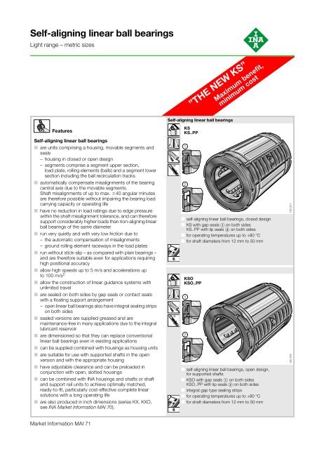
UnitsKGSNGKGSNSKGSNOKGSNOS˚C˚C120 416120 41716■ housing made from high strength aluminium alloy,fitted with self-<strong>aligning</strong> <strong>linear</strong> <strong>ball</strong> bearing KS..PP,bearing can be relubricated■ KGSNS slotted and with adjustable clearance■ for operating temperatures up to +80 °C■ for shaft diameters from 12 mm to 50 mm■KGSCKGSCS18■ housing made from high strength aluminium alloy,open design, suitable for supported shafts,fitted with self-<strong>aligning</strong> <strong>linear</strong> <strong>ball</strong> bearing KSO..PP,bearing can be lubricated■ KGSNOS slotted and with adjustable clearance■ for operating temperatures up to +80 °C■ for shaft diameters from 12 mm to 50 mmUnits – ■tandem ar<strong>range</strong>mentKTFS˚C˚C120 418120 419■ housing made from high strength aluminium alloy,open design, suitable for supported shafts,fitted with self-<strong>aligning</strong> <strong>linear</strong> <strong>ball</strong> bearing KSO..PP,bearing can be lubricated■ KGSCS slotted and with adjustable clearance■ for operating temperatures up to +80 °C■ for shaft diameters from 20 mm to 50 mm■ housing made from high strength aluminium alloy,fitted with two self-<strong>aligning</strong> <strong>linear</strong> <strong>ball</strong> <strong>bearings</strong> KS..PP intandem ar<strong>range</strong>ment, <strong>bearings</strong> can be relubricated■ for operating temperatures up to +80 °C■ for shaft diameters from 12 mm to 30 mm20223
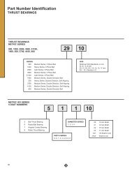
ShaftsShaftsFeaturesShafts■ are precision raceways for INA <strong>linear</strong> <strong>ball</strong> <strong>bearings</strong>■ are made from quenched and tempered steel witha surface hardness of 670 +170 HV (59 +6 HRC)– the uniform hardness depth ensures a smooth transitionfrom the hardened surface layer to the tough core■ can be loaded up to the full basic load rating of INAself-<strong>aligning</strong> <strong>linear</strong> <strong>ball</strong> <strong>bearings</strong>■ are produced as standard in tolerance class h6■ have high accuracy (roundness and parallelism)■ can be supplied in single pieces up to 6 000 mm inlength – depending on the diameter– longer lengths are available by agreement– the shaft ends are chamfered after cutting to length■ can also be supplied in a special version with ends thatdiffer from the standard version■ can be produced with axial or radial threaded holes forfixing (see Threaded holes)■ allow the construction of <strong>linear</strong> guidance systems withhigh load carrying capacity, high rigidity, high accuracyand a long operating life■ can be <strong>com</strong>bined with INA <strong>linear</strong> <strong>ball</strong> <strong>bearings</strong> or INA<strong>linear</strong> <strong>ball</strong> bearing units to achieve optimally matched,ready-to-fit, particularly cost-effective shaft guidancesystems■ are used not only as raceways for INA <strong>linear</strong> <strong>ball</strong> <strong>bearings</strong>but also as:– guide rods for plain bushes– column guides for stud and yoke type track rollers– drawing and straightening rollers– shafts and axles in a wide variety of differentapplications.24W■ high precision solid shaft made from quenched andtempered steel■ standard tolerance h6– special tolerances available by agreement■ diameters from 5 mm to 80 mmThreaded holes120 368120 369■ re<strong>com</strong>mended radial and axial threaded holes for fixing ofhigh precision solid shafts W– for possible <strong>com</strong>binations see Dimension table■ shaft diameters from 5 mm to 80 mm254
Dimension tables5
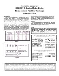
<strong>Self</strong>-<strong>aligning</strong> <strong>linear</strong><strong>ball</strong> <strong>bearings</strong>Main loaddirectionC 7C 1<strong>Light</strong> <strong>range</strong> – <strong>metric</strong> sizesclosed and open designsgap seals orcontact seals on both sidesDD d 1Series KSKS..PPKSOKSO..PPKS, KS..PPC120 384Dimension table · Dimensions in mmShaftdiameterSeries Mass Dimensions MountingdimensionsKS 1) KS..PP 2) KSO 1) KSO..PP 2) d D C A 3) 6 C 1d Designation Designation Designation Designation kg H1312 KS 12 KS 12 PP – – 0,018 12 22 32 – 22,6– – KSO 12 KSO 12 PP 0,013 12 22 32 7,6 –16 KS 16 KS 16 PP – – 0,028 16 26 36 – 24,6– – KSO 16 KSO 16 PP 0,019 16 26 36 10,1 –20 KS 20 KS 20 PP – – 0,051 20 32 45 – 31,2– – KSO 20 KSO 20 PP 0,038 20 32 45 10 –25 KS 25 KS 25 PP – – 0,102 25 40 58 – 43,7– – KSO 25 KSO 25 PP 0,075 25 40 58 12,5 –30 KS 30 KS 30 PP – – 0,172 30 47 68 – 51,7– – KSO 30 KSO 30 PP 0,135 30 47 68 14,3 –40 KS 40 KS 40 PP – – 0,335 40 62 80 – 60,3– – KSO 40 KSO 40 PP 0,259 40 62 80 18,2 –50 KS 50 KS 50 PP – – 0,589 50 75 100 – 77,3– – KSO 50 KSO 50 PP 0,454 50 75 100 22,7 –1) Gap seals on both sides.2) Contact seals on both sides.3) Dimension A 6 on diameter d.4) Hole ar<strong>range</strong>ment sym<strong>metric</strong>al with bearing width C.5) The basic load ratings apply only to hardened (670 +170 HV) and ground shaft raceways.Basic load ratings in accordance with DIN 636-1.6) Basic load rating in main load direction.±40Compensation of misalignments 40120 3586
Main loaddirectionDdA 6C120 386120 385KSO, KSO..PPMain load directionKSO, KSO..PPC 7 D 1 H 10 K 4) 1 K 4) 4 Quantity dyn.C maxBall rows Basic load ratings 5)6) Suitable snap ringto DIN 471stat.C 0maxDegrees kN kN d1,3 21 – 3 – – 8 0,9 0,81 221,2 12– – – 3 3 78 6 0,9 0,81 –1,3 25 – 3 – – 8 1,43 1,16 261,2 16– – – 3 3 78 6 1,43 1,16 –1,6 30,7 – 3 – – 8 2,2 1,73 321,5 20– – – 3 3 60 6 2,2 1,73 –1,85 38 – 3,5 – – 8 3,95 3,25 421,75 25– – 1,5 3,5 3 60 6 3,95 3,25 –1,85 44,7 – 3,5 – – 8 5,9 4,5 481,75 30– – 2 3,5 3 57 6 5,9 4,5 –2,15 59,4 – 3,5 – – 8 10,2 7,2 632 40– – 1,5 3,5 3 54 6 10,2 7,2 –2,65 71,4 – 4,5 – – 8 15,1 10,4 752,5 50– – 2,5 4,5 5 54 6 15,1 10,4 –Shaftdiameter2,35K 4dK 17ºd dK 1H 10KK K 4 4 = 1dK 1K 4H 10KS 12KSO 12KS 16, 20KSO 16, 20KS 25KSO 25KS 30, 40, 50KSO 30, 40, 50Fixing holes120 3877
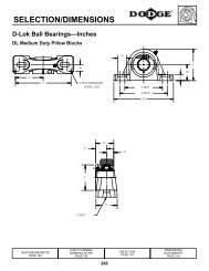
Linear<strong>ball</strong> bearing unitsAA 1C1C 3closed and open designscontact seals on both sidesSeries KGSG..PPKGSS..PPKGSO..PPHK3K5H8H2DdA 4C120 388KGSG..PPDimension table · Dimensions in mmShaftdiameterSeries Mass Dimensions Mounting dimensionsKGSG..PP KGSS..PP KGSO..PP d A C H A 1 A 4 A 1) 6d Designation Designation Designation kg 0,1512 KGSG 12 PP – – 0,08 12 52 32 35,8 42 31,6 –– KGSS 12 PP – 0,08 12 52 32 35,8 42 31,6 –– – KGSO 12 PP 0,07 12 52 32 – 42 31,6 7,616 KGSG 16 PP – – 0,13 16 56 36 37,5 46 35 –– KGSS 16 PP – 0,13 16 56 36 37,5 46 35 –– – KGSO 16 PP 0,12 16 56 36 – 46 35 10,120 KGSG 20 PP – – 0,27 20 70 45 47,5 58 45 –– KGSS 20 PP – 0,27 20 70 45 47,5 58 45 –– – KGSO 20 PP 0,23 20 70 45 – 58 45 1025 KGSG 25 PP – – 0,51 25 80 58 57,5 68 55 –– KGSS 25 PP – 0,51 25 80 58 57,5 68 55 –– – KGSO 25 PP 0,44 25 80 58 – 68 55 12,530 KGSG 30 PP – – 0,83 30 88 68 66,5 76 63 –– KGSS 30 PP – 0,83 30 88 68 66,5 76 63 –– – KGSO 30 PP 0,73 30 88 68 – 76 63 13,640 KGSG 40 PP – – 1,21 40 108 80 83,5 94 77 –– KGSS 40 PP – 1,21 40 108 80 83,5 94 77 –– – KGSO 40 PP 1,05 40 108 80 – 94 77 18,250 KGSG 50 PP – – 2,53 50 135 100 98 116 96 –– KGSS 50 PP – 2,53 50 135 100 98 116 96 –– – KGSO 50 PP 1,98 50 135 100 – 116 96 22,71) Dimensions A 6 on diameter d.2) For fixing screws to EN ISO 4762-8.8.If there is a possibility of settling, the fixing screws should be secured against rotation.3) The basic load ratings apply only to hardened (670 +170 HV) and ground shaft raceways.Basic load ratings in accordance with DIN 636-1.8
120 395A 6H 1KGSO..PP KGSO..PP KGSS..PP120 407A/F120 393Ball rows Basic load ratings 3) ShaftC 1 C 3 D H 1 H 2 H 8 K 2) 3 K 2) 5 A/F Quantity dyn.C maxstat.C 0maxdiameter0,015 Degrees kN kN d20 12 22 – 20 6 5,5 10 – – 8 0,9 0,81 1220 12 22 – 20 6 5,5 10 – 2 8 0,9 0,8120 12 22 32,3 20 6 5,5 10 78 – 6 0,9 0,8122 15 26 – 20 6 5,5 10 – – 8 1,43 1,16 1622 15 26 – 20 6 5,5 10 – 2 8 1,43 1,1622 15 26 33,6 20 6 5,5 10 78 – 6 1,43 1,1628 20 32 – 25 8 6,6 11 – – 8 2,2 1,73 2028 20 32 – 25 8 6,6 11 – 3 8 2,2 1,7328 20 32 44,5 25 8 6,6 11 60 – 6 2,2 1,7340 28 40 – 30 10 6,6 11 – – 8 3,95 3,25 2540 28 40 – 30 10 6,6 11 – 3 8 3,95 3,2540 28 40 53,8 30 10 6,6 11 60 – 6 3,95 3,2548 32 47 – 35 10 6,6 11 – – 8 5,9 4,5 3048 32 47 – 35 10 6,6 11 – 4 8 5,9 4,548 32 47 63,1 35 10 6,6 11 54 – 6 5,9 4,556 40 62 – 45 12 9 15 – – 8 10,2 7,2 4056 40 62 – 45 12 9 15 – 4 8 10,2 7,256 40 62 79,3 45 12 9 15 54 – 6 10,2 7,272 52 75 – 50 14 11 18 – – 8 15,1 10,4 5072 52 75 – 50 14 11 18 – 5 8 15,1 10,472 52 75 92,8 50 14 11 18 54 – 6 15,1 10,49
Linear<strong>ball</strong> bearing unitsclosed and open designscontact seals on both sidesSeries KGSAG..PPKGSAS..PPKGSAO..PPAA1A5K3K5H8H 2HDCC1C2dKGSAG..PPC3120 396Dimension table · Dimensions in mmShaftdiameterSeries Mass Dimensions Mounting dimensionsKGSAG..PP KGSAS..PP KGSAO..PP d A C H A 1 A 5 A 1) 6d Designation Designation Designation kg 0,1512 KGSAG 12 PP – – 0,06 12 42 32 34 32 21 –– KGSAS 12 PP – 0,06 12 42 32 34 32 21 –– – KGSAO 12 PP 0,05 12 42 32 – 32 21 7,616 KGSAG 16 PP – – 0,11 16 50 36 41 40 25 –– KGSAS 16 PP – 0,11 16 50 36 41 40 25 –– – KGSAO 16 PP 0,1 16 50 36 – 40 25 10,120 KGSAG 20 PP – – 0,17 20 60 45 47,5 45 30 –– KGSAS 20 PP – 0,17 20 60 45 47,5 45 30 –– – KGSAO 20 PP 0,15 20 60 45 – 45 30 1025 KGSAG 25 PP – – 0,34 25 74 58 60 60 37 –– KGSAS 25 PP – 0,34 25 74 58 60 60 37 –– – KGSAO 25 PP 0,3 25 74 58 – 60 37 12,530 KGSAG 30 PP – – 0,54 30 84 68 67 68 42 –– KGSAS 30 PP – 0,54 30 84 68 67 68 42 –– – KGSAO 30 PP 0,48 30 84 68 – 68 42 13,640 KGSAG 40 PP – – 0,98 40 108 80 87 86 54 –– KGSAS 40 PP – 0,98 40 108 80 87 86 54 –– – KGSAO 40 PP 0,84 40 108 80 – 86 54 18,250 KGSAG 50 PP – – 1,63 50 130 100 98 108 65 –– KGSAS 50 PP – 1,63 50 130 100 98 108 65 –– – KGSAO 50 PP 1,17 50 130 100 – 108 65 22,71) Dimensions A 6 on diameter d.2) For fixing screws to EN ISO 4762-8.8.If there is a possibility of settling, the fixing screws should be secured against rotation.3) The basic load ratings apply only to hardened (670 +170 HV) and ground shaft raceways.Basic load ratings in accordance with DIN 636-1.10
H 2H 1120 400KGSAO..PP KGSAO..PP KGSAS..PPA6120 408A/F120 399Ball rows Basic load ratings 3) ShaftC 1 C 2 C 3 D H 1 H 2 H 8 K 2) 3 K 2) 5 A/F Quantity dyn.C maxstat.C 0maxdiameter0,15 h5 0,01 –0,5 Degrees kN kN d32 23 20 22 – 18 4,8 4,7 8 – – 8 0,9 0,81 1232 23 20 22 – 18 4,8 4,7 8 – 7 8 0,9 0,8132 23 20 22 30,4 18 4,8 4,7 8 78 – 6 0,9 0,8135 26 22 26 – 22 5,4 4,7 8 – – 8 1,43 1,16 1635 26 22 26 – 22 5,4 4,7 8 – 7 8 1,43 1,1635 26 22 26 36,8 22 5,4 4,7 8 78 – 6 1,43 1,1642 32 28 32 – 25 6,7 4,7 8 – – 8 2,2 1,73 2042 32 28 32 – 25 6,7 4,7 8 – 7 8 2,2 1,7342 32 28 32 44,5 25 6,7 4,7 8 60 – 6 2,2 1,7354 40 40 40 – 30 7,8 5,7 10 – – 8 3,95 3,25 2554 40 40 40 – 30 7,8 5,7 10 – 8 8 3,95 3,2554 40 40 40 56 30 7,8 5,7 10 60 – 6 3,95 3,2560 45 48 47 – 35 8,7 6,8 11 – – 8 5,9 4,5 3060 45 48 47 – 35 8,7 6,8 11 – 10 8 5,9 4,560 45 48 47 63,5 35 8,7 6,8 11 54 – 6 5,9 4,578 58 56 62 – 45 11 9,2 15 – – 8 10,2 7,2 4078 58 56 62 – 45 11 9,2 15 – 13 8 10,2 7,278 58 56 62 82,4 45 11 9,2 15 54 – 6 10,2 7,270 50 72 75 – 50 12,5 9,2 15 – – 8 15,1 10,4 5070 50 72 75 – 50 12,5 9,2 15 – 13 8 15,1 10,470 50 72 75 92,8 50 12,5 9,2 15 54 – 6 15,1 10,411
Linear<strong>ball</strong> bearing units<strong>Light</strong> <strong>range</strong> – <strong>metric</strong> sizessealed, greased,with relubrication facilitySeries KGSNG..PP ASKGSNS..PP ASAA 5K 2CH 5H 7 H 8 H 2H 6HdK 8K 4 K 3XA 4KGSNG..PP ASD120 117Dimension table · Dimensions in mmShaftdiameterSeries Mass Dimensions Mounting dimensionsKGSNG..PP AS KGSNS..PP AS d A C H A 1 A 4 A 5 C 21) Dd Designation Designation kg 0,15 0,01 0,1512 KGSNG 12 PP AS – 0,1 12 43 32 35 32 34 21,5 23 22– KGSNS 12 PP AS 0,1 12 43 32 35 32 34 21,5 23 2216 KGSNG 16 PP AS – 0,17 16 53 37 42 40 40 26,5 26 26– KGSNS 16 PP AS 0,17 16 53 37 42 40 40 26,5 26 2620 KGSNG 20 PP AS – 0,27 20 60 45 50 45 44 30 32 32– KGSNS 20 PP AS 0,27 20 60 45 50 45 44 30 32 3225 KGSNG 25 PP AS – 0,56 25 78 58 60 60 59,4 39 40 40– KGSNS 25 PP AS 0,56 25 78 58 60 60 59,4 39 40 4030 KGSNG 30 PP AS – 0,83 30 87 68 70 68 63 43,5 45 47– KGSNS 30 PP AS 0,83 30 87 68 70 68 63 43,5 45 4740 KGSNG 40 PP AS – 1,55 40 108 80 90 86 76 54 58 62– KGSNS 40 PP AS 1,55 40 108 80 90 86 76 54 58 6250 KGSNG 50 PP AS – 2,7 50 132 100 105 108 90 66 50 75– KGSNS 50 PP AS 2,7 50 132 100 105 108 90 66 50 751) Dimension C 2 and lubrication hole sym<strong>metric</strong>al with bearing width C.2) For fixing screws to EN ISO 4762-8.8.If there is a possibility of settling, the fixing screws should be secured against rotation.3) Centring for dowel hole.4) The basic load ratings apply only to hardened (670 +170 HV) and ground shaft raceways.12
CA1dDC2A/FK5X120 118a120 118b120 414KGSNS..PP AS View X (rotated 90°)Ball rowsBasic loadratings 4)H 2 H 5 H 6 H 7 H 8 K 2 K 2) 3 K 3) 4 K 2) 5 K 1) 8 A/F Quantity dyn.C maxstat.C 0max+0,008–0,016 kN kN d18 5,4 25,3 11 16,5 M 5 4,3 4 8 NIP 4 MZ – 8 0,9 0,81 1218 5,4 25,3 11 16,5 M 5 4,3 4 8 NIP 4 MZ 2,5 8 0,9 0,8122 6,9 28 13 21 M 6 5,3 4 10 NIP 4 MZ – 8 1,43 1,16 1622 6,9 28 13 21 M 6 5,3 4 10 NIP 4 MZ 3 8 1,43 1,1625 7,4 32,8 18 24 M 8 6,6 5 11 NIP 4 MZ – 8 2,2 1,73 2025 7,4 32,8 18 24 M 8 6,6 5 11 NIP 4 MZ 4 8 2,2 1,7330 8,3 40 22 29 M10 8,4 6 15 NIP 5 MZ – 8 3,95 3,25 2530 8,3 40 22 29 M10 8,4 6 15 NIP 5 MZ 5 8 3,95 3,2535 9,3 44,7 22 34 M10 8,4 6 15 NIP 5 MZ – 8 5,9 4,5 3035 9,3 44,7 22 34 M10 8,4 6 15 NIP 5 MZ 5 8 5,9 4,545 11,7 55,9 26 44 M12 10,5 8 18 NIP 5 MZ – 8 10,2 7,2 4045 11,7 55,9 26 44 M12 10,5 8 18 NIP 5 MZ 6 8 10,2 7,250 10,6 60 35 49 M16 13,5 10 20 NIP 6 MZ – 8 15,1 10,4 5050 10,6 60 35 49 M16 13,5 10 20 NIP 6 MZ 8 8 15,1 10,4Shaftdiameter13
Linear<strong>ball</strong> bearing unitsAA 5K 2C<strong>Light</strong> <strong>range</strong> – <strong>metric</strong> sizesK 8H 5 H 7 H 8sealed, greased,with relubrication facilityHdDSeries KGSNO..PP ASKGSNOS..PP ASH 2K 4A 6KGSNO..PP ASK 3 K 5A 1X120 119Dimension table · Dimensions in mmShaftdiameterSeries Mass Dimensions Mounting dimensionsKGSNO..PP AS KGSNOS..PP AS d A C H A 1 A 5 A 1) 6 C 2) 2 Dd Designation Designation kg 0,15 0,01 0,1512 KGSNO 12 PP AS – 0,09 12 43 32 28 32 21,5 7,6 23 22– KGSNOS 12 PP AS 0,09 12 43 32 28 32 21,5 7,6 23 2216 KGSNO 16 PP AS – 0,15 16 53 37 35 40 26,5 8,9 26 26– KGSNOS 16 PP AS 0,15 16 53 37 35 40 26,5 8,9 26 2620 KGSNO 20 PP AS – 0,25 20 60 45 42 45 30 9,2 32 32– KGSNOS 20 PP AS 0,25 20 60 45 42 45 30 9,2 32 3225 KGSNO 25 PP AS – 0,52 25 78 58 51 60 39 11,9 40 40– KGSNOS 25 PP AS 0,52 25 78 58 51 60 39 11,9 40 4030 KGSNO 30 PP AS – 0,76 30 87 68 60 68 43,5 14,3 45 47– KGSNOS 30 PP AS 0,76 30 87 68 60 68 43,5 14,3 45 4740 KGSNO 40 PP AS – 1,4 40 108 80 77 86 54 18,8 58 62– KGSNOS 40 PP AS 1,4 40 108 80 77 86 54 18,8 58 6250 KGSNO 50 PP AS – 2,4 50 132 100 88 108 66 22,7 50 75– KGSNOS 50 PP AS 2,4 50 132 100 88 108 66 22,7 50 751) Dimension A 6 on diameter d.2) Dimension C 2 and lubrication hole sym<strong>metric</strong>al with bearing width C.3) For fixing screws to EN ISO 4762-8.8.If there is a possibility of settling, the fixing screws should be secured against rotation.4) The basic load ratings apply only to hardened (670 +170 HV) and ground shaft raceways.5) Centring hole to DIN 332, type A.14
CC 2dDA/FXA 1KGSNOS..PP AS View X (rotated 90°)120 120a120 256c120 120bBall rows Basic load ratings 4) ShaftH 2 H 5 H 7 H 8 K 2 K 3) 3 K 5) 4 K 3) 5 K 2) 8 A/F Quantity dyn.C maxstat.C 0maxdiameter+0,008–0,016 Degrees kN kN d18 6,1 11 16,5 M 5 4,3 1,6 3,35 8 NIP 4 MZ – 78 6 0,9 0,81 1218 6,1 11 16,5 M 5 4,3 1,6 3,35 8 NIP 4 MZ 2,5 78 6 0,9 0,8122 7,5 13 21 M 6 5,3 1,6 3,35 10 NIP 4 MZ – 68 6 1,43 1,16 1622 7,5 13 21 M 6 5,3 1,6 3,35 10 NIP 4 MZ 2,5 68 6 1,43 1,1625 8 18 24 M 8 6,6 2 4,25 11 NIP 4 MZ – 55 6 2,2 1,73 2025 8 18 24 M 8 6,6 2 4,25 11 NIP 4 MZ 2,5 55 6 2,2 1,7330 8,8 22 29 M10 8,4 2,5 5,3 15 NIP 5 MZ – 57 6 3,95 3,25 2530 8,8 22 29 M10 8,4 2,5 5,3 15 NIP 5 MZ 3 57 6 3,95 3,2535 9,7 22 34 M10 8,4 2,5 5,3 15 NIP 5 MZ – 57 6 5,9 4,5 3035 9,7 22 34 M10 8,4 2,5 5,3 15 NIP 5 MZ 3 57 6 5,9 4,545 12,4 26 44 M12 10,5 3,15 6,7 18 NIP 5 MZ – 56 6 10,2 7,2 4045 12,4 26 44 M12 10,5 3,15 6,7 18 NIP 5 MZ 4 56 6 10,2 7,250 11,1 35 49 M16 13,5 4 8,5 20 NIP 6 MZ – 54 6 15,1 10,4 5050 11,1 35 49 M16 13,5 4 8,5 20 NIP 6 MZ 5 54 6 15,1 10,415
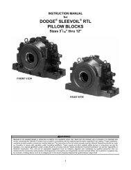
Linear<strong>ball</strong> bearing unitsclosed and open designscontact seals on both sidesSeries KTSG..PP ASKTSS..PP ASHK 8AA 5K2H 5 H7 H8 H 2K4 K 3dCDKTSG..PP AS120 401Dimension table · Dimensions in mmShaftdiameterSeries Mass Dimensions Mounting dimensionsKTSG..PP AS KTSS..PP AS d A C H A 1 A 5 C 1) 2 C 1) 3 Dd Designation Designation kg 0,15 0,01 0,1512 KTSG 12 PP AS – 0,21 12 43 70 35 32 21,5 56 24 22– KTSS 12 PP AS 0,21 12 43 70 35 32 21,5 56 24 2216 KTSG 16 PP AS – 0,38 16 53 78 42 40 26,5 64 26 26– KTSS 16 PP AS 0,38 16 53 78 42 40 26,5 64 26 2620 KTSG 20 PP AS – 0,55 20 60 96 50 45 30 76 33 32– KTSS 20 PP AS 0,55 20 60 96 50 45 30 76 33 3225 KTSG 25 PP AS – 1,13 25 78 122 60 60 39 94 44 40– KTSS 25 PP AS 1,13 25 78 122 60 60 39 94 44 4030 KTSG 30 PP AS – 1,78 30 87 142 70 68 43,5 106 54 47– KTSS 30 PP AS 1,78 30 87 142 70 68 43,5 106 54 471) Dimensions and lubrication hole sym<strong>metric</strong>al with bearing width C.2) For fixing screws to EN ISO 4762-8.8.If there is a possibility of settling, the fixing screws should be secured against rotation.3) Centring for dowel hole.4) Lubrication nipple.5) The basic load ratings apply only to hardened (670 +170 HV) and ground shaft raceways.Basic load ratings in accordance with DIN 636-1.16
C 2C 3K 8A/FX120 402K 5A 1120 403KTSS..PP AS(same dimensions as KTSG..PP AS)View X (rotated 90°)Ball rows Basic load ratings 5) ShaftH 2 H 5 H 6 H 7 H 8 K 2 K 2) 3 K 3) 4 K 2) 5 K 4) 8 A/F Quantity dyn.C maxstat.C 0maxdiameter+0,008–0,016 kN kN d18 6 25,3 11 16,5 M 5 4,3 4 8 NIP 4 MZ – 8 1,46 1,62 1218 6 25,3 11 16,5 M 5 4,3 4 8 NIP 4 MZ 2,5 8 1,46 1,6222 7,5 28 13 21 M 6 5,3 4 10 NIP 4 MZ – 8 2,33 2,32 1622 7,5 28 13 21 M 6 5,3 4 10 NIP 4 MZ 3 8 2,33 2,3225 8 32,8 18 24 M 8 6,6 5 11 NIP 4 MZ – 8 3,65 3,45 2025 8 32,8 18 24 M 8 6,6 5 11 NIP 4 MZ 4 8 3,65 3,4530 9 40 22 29 M10 8,4 6 15 NIP 5 MZ – 8 6,4 6,5 2530 9 40 22 29 M10 8,4 6 15 NIP 5 MZ 5 8 6,4 6,535 10 44,7 22 34 M10 8,4 6 15 NIP 5 MZ – 8 9,6 9 3035 10 44,7 22 34 M10 8,4 6 15 NIP 5 MZ 5 8 9,6 917
Linear<strong>ball</strong> bearing unitsopen designcontact seals on both sidesAA 5K2H 5 H 7 H 8 H2CSeries KTSO..PP ASKTSOS..PP ASHK 8dDAK 64 K 3K 5A 1KTSO..PP ASC 2120 404Dimension table · Dimensions in mmShaftdiameterSeries Mass Dimensions Mounting dimensionsKTSO..PP AS KTSOS..PP AS d A C H A 1 A 5 A 1) 6 C 2) 2 C 2) 3 Dd Designation Designation kg 0,15 0,01 0,1512 KTSO 12 PP AS – 0,176 12 43 70 28 32 21,5 6,5 56 24 22– KTSOS 12 PP AS 0,18 12 43 70 28 32 21,5 6,5 56 24 2216 KTSO 16 PP AS – 0,34 16 53 78 35 40 26,5 8,9 64 26 26– KTSOS 16 PP AS 0,34 16 53 78 35 40 26,5 8,9 64 26 2620 KTSO 20 PP AS – 0,51 20 60 96 42 45 30 9,2 76 33 32– KTSOS 20 PP AS 0,51 20 60 96 42 45 30 9,2 76 33 3225 KTSO 25 PP AS – 1,03 25 78 122 51 60 39 11,9 94 44 40– KTSOS 25 PP AS 1,03 25 78 122 51 60 39 11,9 94 44 4030 KTSO 30 PP AS – 1,8 30 87 142 60 68 43,5 14,3 106 54 47– KTSOS 30 PP AS 1,8 30 87 142 60 68 43,5 14,3 106 54 471) Dimensions A 6 on diameter d.2) Dimensions and lubrication hole sym<strong>metric</strong>al with bearing width C.3) For fixing screws to EN ISO 4762-8.8.If there is a possibility of settling, the fixing screws should be secured against rotation.4) Lubrication nipple.5) The basic load ratings apply only to hardened (670 +170 HV) and ground shaft raceways.Basic load ratings in accordance with DIN 636-1.6) Centring hole to DIN 332, type A.18
C 3A 1XA/F120 405C 2120 406KTSOS..PP AS(same dimensions as KTSO..PP AS)View X (rotated 90°)Ball rows Basic load ratings 5) ShaftH 2 H 5 H 7 H 8 K 2 K 3) 3 K 6) 4 K 3) 5 K 4) 8 A/F Quantity dyn.C maxstat.C 0maxdiameter+0,008–0,016 Degrees kN kN d18 6,1 11 16,5 M 5 4,3 1,63,35 8 NIP 4 MZ – 66 6 1,46 1,62 1218 6,1 11 16,5 M 5 4,3 1,63,35 8 NIP 4 MZ 2,5 66 6 1,46 1,6222 7,5 13 21 M 6 5,3 1,63,35 10 NIP 4 MZ – 68 6 2,33 2,32 1622 7,5 13 21 M 6 5,3 1,63,35 10 NIP 4 MZ 2,5 68 6 2,33 2,3225 8 18 24 M 8 6,6 2,04,25 11 NIP 4 MZ – 55 6 3,65 3,45 2025 8 18 24 M 8 6,6 2,04,25 11 NIP 4 MZ 2,5 55 6 3,65 3,4530 8,8 22 29 M10 8,4 2,55,3 15 NIP 5 MZ – 57 6 6,4 6,5 2530 8,8 22 29 M10 8,4 2,55,3 15 NIP 5 MZ 3 57 6 6,4 6,535 9,7 22 34 M10 8,4 2,55,3 15 NIP 5 MZ – 57 6 9,6 9 3035 9,7 22 34 M10 8,4 2,55,3 15 NIP 5 MZ 3 57 6 9,6 919
Linear<strong>ball</strong> bearing units<strong>Light</strong> <strong>range</strong> – <strong>metric</strong> sizessealed, greased,with relubrication facilitySeries KGSC..PP ASKGSCS..PP ASHH8H 6H 7K 4AA 3A 2K 2 A 5H 5H 2A 6dCDK 3K 5K 8C 2C 3120 121KGSC..PP ASDimension table · Dimensions in mmShaftdiameterSeries Mass Dimensions Mounting dimensionsKGSC..PP AS KGSCS..PP AS d A C H A 2 A 3 A 5 A 61) C 22) C 32)d Designation Designation kg 0,15 0,01 0,1520 KGSC 20 PP AS – 0,35 20 60 47 60 39 51 17 9,2 30 36– KGSCS 20 PP AS 0,35 20 60 47 60 39 51 17 9,2 30 3625 KGSC 25 PP AS – 0,68 25 75 58 72 49 64 21 12 36 45– KGSCS 25 PP AS 0,68 25 75 58 72 49 64 21 12 36 4530 KGSC 30 PP AS – 1 30 86 68 82 59 76 25 14,3 42 52– KGSCS 30 PP AS 1 30 86 68 82 59 76 25 14,3 42 5240 KGSC 40 PP AS – 1,8 40 110 80 100 75 97 32 18,8 48 60– KGSCS 40 PP AS 1,8 40 110 80 100 75 97 32 18,8 48 6050 KGSC 50 PP AS – 2,9 50 127 100 115 88 109 38 22,7 62 80– KGSCS 50 PP AS 2,9 50 127 100 115 88 109 38 22,7 62 801) Dimension A 6 on diameter d.2) Dimension C 2 and lubrication hole sym<strong>metric</strong>al with bearing width C.3) Centring for dowel hole.4) For fixing screws to EN ISO 4762-8.8.If there is a possibility of settling, the fixing screws should be secured against rotation.5) The basic load ratings apply only to hardened (670 +170 HV) and ground shaft raceways.20
A 3CdDC 2K 4A/F120 122aC 3120 122bKGSCS..PP ASBall rowsBasic loadratings 5)D H 2 H 5 H 6 H 7 H 8 K 2 K 3) 3 K 4) 4 K 3) 5 K 2) 8 A/F Quantity dyn.C maxstat.C 0max+0,008–0,016 Degrees kN kN d32 30 8,3 37,5 18 42,6 M10 8,4 6 15 NIP 4 MZ – 55 6 2,2 1,73 2032 30 8,3 37,5 18 42,6 M10 8,4 6 15 NIP 4 MZ 2,5 55 6 2,2 1,7340 35 8,2 45 22 50,6 M12 10,5 8 18 NIP 5 MZ – 57 6 3,95 3,25 2540 35 8,2 45 22 50,6 M12 10,5 8 18 NIP 5 MZ 3 57 6 3,95 3,2547 40 9 52 29 55,6 M16 13,5 10 20 NIP 5 MZ – 57 6 5,9 4,5 3047 40 9 52 29 55,6 M16 13,5 10 20 NIP 5 MZ 3 57 6 5,9 4,562 45 9,5 60 36 67,6 M20 15,5 12 24 NIP 5 MZ – 56 6 10,2 7,2 4062 45 9,5 60 36 67,6 M20 15,5 12 24 NIP 5 MZ 4 56 6 10,2 7,275 50 8,6 70 36 78,8 M20 17,5 12 26 NIP 6 MZ – 54 6 15,1 10,4 5075 50 8,6 70 36 78,8 M20 17,5 12 26 NIP 6 MZ 5 54 6 15,1 10,4Shaftdiameter21
Linear<strong>ball</strong> bearing units<strong>Light</strong> <strong>range</strong> – <strong>metric</strong> sizessealed, greased,with relubrication facilitySeries KTFS..PP ASDimension table · Dimensions in mmShaftdiameterSeries Mass Dimensions Mounting dimensionsKTFS..PP AS d A C H A 1 C 1 C 3 C 7 Dd Designation kg 0,1512 KTFS 12 PP AS 0,2 12 41 70 34 32 40 10 35 2216 KTFS 16 PP AS 0,3 16 50 78 40 38 50 10 39 2620 KTFS 20 PP AS 0,5 20 60 96 50 45 60 10 48 3225 KTFS 25 PP AS 1 25 74 122 60 56 73 10 61 4030 KTFS 30 PP AS 1,4 30 84 142 70 64 82 10 71 471) Re<strong>com</strong>mendation: locating bore D 1 H7.2) The basic load ratings apply only to hardened (670 +170 HV) and ground shaft raceways.22
CC 3 C 1AA 1D 1 D 2 DKTFS..PP ASCH 7 K 2dH H 1 K 8K 3120 127bBall rows Basic load ratings 2) ShaftD 1) 1 D 2 H 1 H 7 K 2 K 3 K 8 Quantity dyn.C maxstat.C 0maxdiameterg7–0,1–0,3 0,15 kN kN d30 30 24 13 M 6 5,3 M81 8 1,46 1,62 1235 35 28 18 M 8 6,6 M81 8 2,33 2,32 1642 42 35 22 M10 8,4 M81 8 3,65 3,45 2052 52 42 26 M12 10,5 M81 8 6,4 6,5 2561 61 50 35 M16 13,5 M81 8 9,6 9 3023
ShaftsSeries Wd LW t 10,3 (R z 2)t 2 /10000,1/1 000WL120 030Dimension table · Dimensions in mmShaftdiameterDesignation Mass Length Tolerances in m Roundness Parallelism SurfacehardnessStandard Special tolerances 1)depthtoleranced LW L max h6 j5 f7 t 1 t 22) Rht 3)1) Only for shafts made from quenched and tempered steel.2) Measured diameter variation.3) According to DIN 6 773, Part 3.kg/m m m min.5 W 5 0,15 3 600 0– 8 – – 4 5 0,46 W 6 0,22 4 000 0– 8 – – 4 5 0,48 W 8 0,39 4 000 0– 9 – – 4 6 0,410 W 10 0,61 4 000 0– 9 – – 4 6 0,412 W 12 0,89 6 000 0–11 +5–3 –16–34 5 8 0,614 W 14 1,21 6 000 0–11 +5–3 –16–34 5 8 0,615 W 15 1,37 6 000 0–11 – –16–34 5 8 0,616 W 16 1,57 6 000 0–11 +5–3 –16–34 5 8 0,618 W 18 1,98 6 000 0–11 – –16–34 5 8 0,620 W 20 2,45 6 000 0–13 +5–4 –20–41 6 9 0,924 W 24 3,55 6 000 0–13 – – 6 9 0,925 W 25 3,83 6 000 0–13 +5–4 –20–41 6 9 0,930 W 30 5,51 6 000 0–13 +5–4 –20–41 6 9 0,932 W 32 6,3 6 000 0–16 – –25–50 7 11 1,540 W 40 9,8 6 000 0–16 +6–5 – 7 11 1,550 W 50 15,3 6 000 0–16 +6–5 – 7 11 1,560 W 60 22,1 6 000 0–19 – – 8 13 2,280 W 80 39,2 6 000 0–19 – – 8 13 2,224
Re<strong>com</strong>mendedthreaded holesd LW K 6H H 7 8K 72 x K 6K 5C 5 C 4C 6Re<strong>com</strong>mended threaded holes for shafts W120 179Dimension table · Dimensions in mmShaftdiameter 1) Axial threaded hole Radial threaded holeDimensionsK 6 C 4 C 5min , C 2) 6min H 7 H 8 K 5 K 703 04–05– – – –W 8 M3 – – – – – – – – – – – – –W 25 – – – – – – – – – – – – 150 15 11 3 7 M63K 6 +K 7W 25 – – – – M8 M10 M12 – – – 75 120 200 15 15 3 9 M8W 10 M3 M4 – – – – – – – – – – – – – – – –W 12 – M4 M5 – – – – – – – 75 – 120 10 7 2 5 M4W 14 – M4 M5 M6 – – – – – – – – – – – – – –W 15 – – M5 M6 M8 – – – – – – – – – – – – –W 16 – – M5 M6 M8 – – – – – 75 100 150 15 9 2,5 6 M5W 18 – – – M6 M8 M10 – – – – – – – – – – – –W 20 – – – – – – – – – – – – 150 15 9 2,5 6 M5W 20 – – – M6 M8 M10 – – – – 75 100 150 15 11 3 7 M6W 24 – – – – M8 M10 M12 – – – – – – – – – – –W 30 – – – – – – – – – – – – 150 15 11 3 7 M6W 30 – – – – – M10 M12 M16 – – 100 150 200 20 17 3,5 11 M10W 32 – – – – – M10 M12 M16 – – – – – – – – – –W 40 – – – – – M10 M12 M16 – – 150 200 300 20 19 4 11 M10W 40 – – – – – M10 M12 M16 – – 100 – – 20 21 4 13 M12W 50 – – – – – – – – – – – – 150 20 19 4 11 M10W 50 – – – – – – M12 M16 M20 – – 200 300 20 21 4 13 M12W 50 – – – – – – M12 M16 M20 – 100 – – 20 25 4 15 M14W 60 – – – – – – – M16 M20 M24 – – – – – – – –W 80 – – – – – – – M16 M20 M24 – – – – – – – –1) For dimensions, see page 24.2) C 5 and C 6 are dependent on the shaft length.For versions with hole patterns 04 and 05,the axial threaded hole must be taken into consideration.Hole pattern 01Hole pattern 02Hole pattern 03Hole pattern 04Hole pattern 05120 40925
INA-Schaeffler KGLinear Technology Division66406 Homburg (Saar) · GermanyInternet www.ina.<strong>com</strong>E-Mail info.<strong>linear</strong>@de.ina.<strong>com</strong>In Germany:Telephone 0180 / 5 00 38 72Fax 0180/5003873From other countries:Telephone +49 / 68 41/7 01-0Fax +49 / 68 41/ 7 01-6 25Sach-Nr. 007-523-599/MAI 71 GB-D 02023 · Printed in Germany